

Page 1
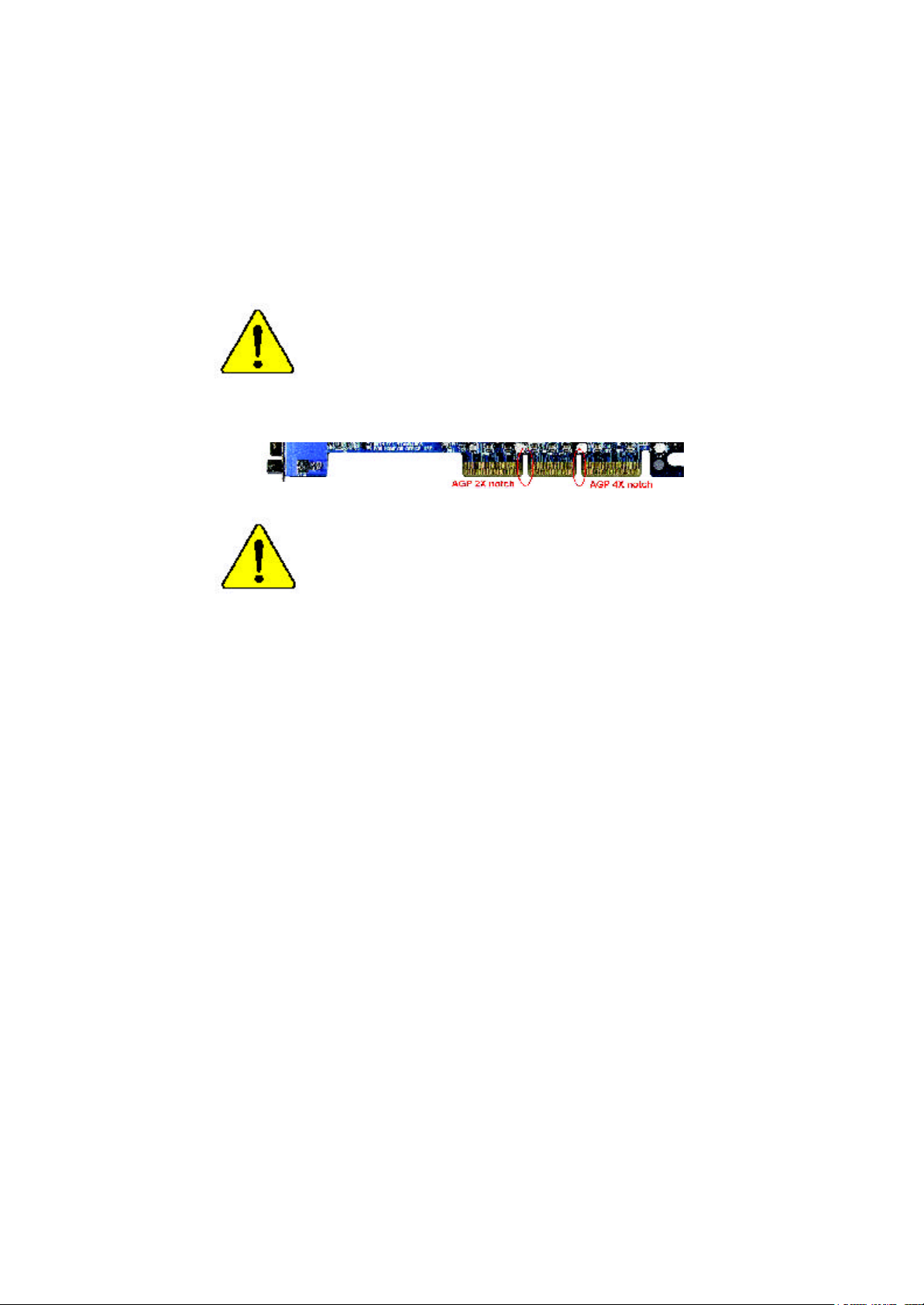
When you installing AGP card, please make sure the following
notice is fully understood and practiced. If your AGP card has
"AGP 4X notch"(show below), please make sure your AGP card is
AGP 4X (1.5V).
Do not use AGP 2X card (3.3V) in this motherboard. It will
burn and damage the motherboard due to Intel® 845 chipset can't
support AGP 2X(3.3V)..
Example 1: Diamond Vipper V770 golden finger is compatible with 2X/
4X mode AGP slot. It can be switched between AGP 2X(3.3V) or 4X(1.
5V) mode by adjusting the jumper. The factory default for this card is 2X
(3.3V). If you install this card in GA-8IRM series (or any AGP 4X only)
motherboards without switching the jumper to 4X mode (1.5V), it will
burn the motherboard.
Example 2: ATi Rage 128 Pro (Power Color)& SiS 305 golden finger is
compatible with 2X/4X mode AGP slot, but it supports 2X(3.3V) only. If
you install this card in GA-8IRM series (or any AGP 4X only)
motherboards, it will burn the motherboard.
Note : Although Gigabyte's AG32S graphics card is based on ATi Rage
128 Pro chip, the design of AG32S is compliance with AGP 4X (1.5V)
specification. Therefore, AG32S will work fine with Intel 845 / 850 based
motherboards.
Page 2
? The author assumes no responsibility for any errors
or omissions that may appear in this document nor
does the author make a commitment to up
date the information contained herein.
? Third-party brands and names are the property of
their respective owners.
? Please do not remove any labels on motherboard, this
may void the warranty of this motherboard.
? Due to rapid change in technology, some of the
specifications might be out of date before publication
of this booklet.
Page 3

A usschlager Weg 41, 1F, 20537 Hambur g, Germany
( descript ion of t he apparatus, system, inst allat ion to which it ref ers)
(ref erence t o t he specif ication under which conf ormit y is declared)
in accordance wit h 89/336 EEC-EMC Directive
? EN 55011 Lim its and m et hods of m easurem ent
? EN 55013
? EN 55014 Lim its and m et hods of m easurem ent
? EN 55015 Lim its and m et hods of m easurem ent
? EN 55020
? EN 55022 Lim its and m et hods of m easurem ent
? DIN VDE 0855
? part 10
? part 12
? CE marking
? EN 60065
? EN 60335
of radio disturbance characteristics of
indust rial,scientific and medical (ISM
high f requency equipment
Lim its and m et hods of m easurem ent
of radio disturbance characteristics of
broadcast receivers and associat ed
equipm ent
of radio disturbance characteristics of
household elect rical appliances,
port able tools and sim ilar elect rical
apparat us
of radio disturbance characteristics of
f luorescent lam ps and lum inaries
Im munity from radio int erference of
broadcast receivers and associat ed
equipm ent
of radio disturbance characteristics of
inf ormat ion t echnology equipm ent
Cabled dist ribution system s; Equipment
f or receiving and/or distribution f rom
sound and t elevision signals
T he manufacturer also declares the conformity of above mentioned product
with the actual required safety standards in accordance with LVD 73/23 EEC
Saf ety requirem ent s f or m ains operat ed
elect ronic and related apparatus f or
household and sim ilar general use
Saf ety of household and sim ilar
elect rical appliances
(S tamp )
Declaration of Conformity
We, Manuf acturer/Importer
(f ull address)
G.B.T. Technology Tr ä ding GMbH
declare t hat t he product
Mother Board
GA-8IRM/GA-8IRML
is in conf ormity with
? EN 61000-3-2*
? EN 60555-2
? EN 61000-3-3* Dist urbances in supply system s cause
? EN 60555-3
? EN 50081-1 Generic em ission st andard Part 1:
? EN 50082-1
? EN 55081-2
? EN 55082-2
? ENV 55104
? EN50091-2
(EC conf ormit y m arking)
? EN 60950
? EN 50091-1
Manufacturer/Importer
Dat e : Nov. 10, 2001
Dist urbances in supply system s cause
by household appliances and sim ilar
elect rical equipment “ Harm onics”
by household appliances and sim ilar
elect rical equipment “ Volt age f luctuations”
Residual com mercial and light indust ry
Generic im munit y st andard Part 1:
Residual com mercial and light indust ry
Generic em ission st andard Part 2:
Indust rial environment
Generic em ission st andard Part 2:
Indust rial environment
lm munit y requirements f or household
appliances t ools and similar apparat us
EMC requirem ents for uninterrupt ible
power syst ems (UPS)
Signat ure:
Nam e:
Ti mmy H u ang
Timm y Huang
Page 4

DECLARATION OF CONFORMITY
Pe r FCC Part 2 Sect ion 2.1077(a)
Respon sible Party Name:
Address:
Ph one/Fax No:
h ereby declares that the product
Product Name:
Model Nu mber:
Con forms to the follo wing specifications:
FCC Part 15, Su b part B, Sectio n 15.107(a) an d Section 15.109
(a),Clas s B Digi tal Device
Su pplementary Information:
Th is device co mplies wi th part 15 of the FCC Rules . Operati on is
s ubject to t he follo wing two conditi ons: (1) This device may not
cau se harmful and (2) this device must accept any inference received,
in cluding that may cause undesired operation.
Repres entative Person’s Name:
Sig nature:
G.B.T. INC. (U.S.A.)
17358 Railroad Street
City of Industry, CA 91 748
(818) 854-9338/ (818) 854-9339
Moth er board
GA-8 IRM/GA-8IRML
ERIC LU
Eric Lu
Date:
Nov . 10,2001
Page 5

GA-8IRM Series
P4 Titan-DDR Motherboard
USER’S MANUAL
Pentium®4 Processor Motherboard
Rev. 2.2 First Edition
12ME-8IRM-2201
Page 6

GA-8IRM Series Motherboard
Table of Content
Revision History ..............................................................................4
Item Checklist ..................................................................................4
WARNING! .......................................................................................5
Chapter 1 Introduction .......................................................................6
Features Summary................................................................................................ 6
GA-8IRM Series Motherboard Layout ............................................................... 8
Chapter 2 Hardware Installation Process ............................................9
Step 1: Install the Central Processing Unit (CPU) .........................................10
CPU Installation . .. .. .. .. .. .. .. .. .. .. .. .. .. .. .. .. .. .. .. .. .. .. .. .. .. .. .. .. .. .. .. .. .. .. .. .. .. .. .. .. .. .. .. .. 10
CPU Heat Sink Installation . .. .. .. .. .. .. .. .. .. .. .. .. .. .. .. .. .. .. .. .. .. .. .. .. .. .. .. .. .. .. .. .. .. .. .. .. .. . 11
Step 2: Install memory modules ....................................................................... 12
Step 3: Install expansion cards ......................................................................... 13
Step 4: Connect ribbon cables, cabinet wires, and power supply ............. 14
I/O Back Panel Introduction .. .. .. .. .. .. .. .. .. .. .. .. .. .. .. .. .. .. .. .. .. .. .. .. .. .. .. .. .. .. .. .. .. .. .. .. .. 14
Connectors Introduction .. .. .. .. .. .. .. .. .. .. .. .. .. .. .. .. .. .. .. .. .. .. .. .. .. .. .. .. .. .. .. .. .. .. .. .. .. .. .. . 16
Chapter 3 BIOS Setup .................................................................... 22
The Main Menu (For example: BIOS Ver. :F3b) ........................................... 23
Standard CMOS Features ................................................................................. 25
Advanced BIOS Features ................................................................................... 28
Advanced Chipset Features .............................................................................. 31
Integrated Peripherals ....................................................................................... 34
2
Page 7

Table of Content
Power Management Setup ................................................................................ 42
PnP/PCI Configurations ...................................................................................... 46
PC Health Status .................................................................................................. 48
Frequency/Voltage Control ................................................................................ 50
Load Fail-Safe Defaults ...................................................................................... 52
Load Optimized Defaults .................................................................................... 53
Set Supervisor/User Password .......................................................................... 54
Save & Exit Setup ................................................................................................. 55
Exit Without Saving .............................................................................................56
Chapter 4 Technical Reference ........................................................57
Performance List ................................................................................................. 57
Block Diagram ..................................................................................................... 58
@ BIOS Introduction ........................................................................................... 59
Easy TuneIIITM Introduction ................................................................................ 60
Chapter 5 Appendix ....................................................................... 61
3
Page 8

GA-8IRM Series Motherboard
Revision History
Revision Revision Note Date
2.2 Initial release of the GA-8IRM Series motherboard user's manual. Feb. 2002
Item Checklist
? The GA-8IRM Series motherboard
? IDE cable x 1/ Floppy cable x 1
? CD for motherboard driver & utility (IUCD)
? I/O Shield
? GA-8IRM Series user’s manual
? USB Cable x 1
4
Page 9

WARNING!
WARNING!
Computer motherboards and expansion cards contain very delicate Integrated Circuit (IC) chips. To
protect them against damage from static electricity, you should follow some precautions whenever you
work on your computer.
1. Unplug your computer when working on the inside.
2. Use a grounded wrist strap before handling computer components. If you do not have
one, touch both of your hands to a safely grounded object or to a metal object, such as
the power supply case.
3. Hold components by the edges and try not touch the IC chips, leads or connectors, or
other components.
4. Place components on a grounded antistatic pad or on the bag that came with the
components whenever the components are separated from the system.
5. Ensure that the ATX power supply is switched off before you plug in or remove the ATX
power connector on the motherboard.
Installing the motherboard to the chassis…
If the motherboard has mounting holes, but they don’t line up with the holes on the base and there are
no slots to attach the spacers, do not become alarmed you can still attach the spacers to the mounting
holes. Just cut the bottom portion of the spacers (the spacer may be a little hard to cut off, so be careful
of your hands). In this way you can still attach the motherboard to the base without worrying about short
circuits. Sometimes you may need to use the plastic springs to isolate the screw from the motherboard
PCB surface, because the circuit wire may be near by the hole. Be careful, don’t let the screw contact
any printed circuit write or parts on the PCB that are near the fixing hole, otherwise it may damage the
board or cause board malfunctioning.
5
Page 10

GA-8IRM Series Motherboard
Chapter 1 Introduction
Features Summary
Form Factor ? 20.7cm x 24.3cm Micro ATX size form factor, 4 layers PCB.
Motherboard ? GA-8IRM Series Motherboard:
GA-8IRM and GA-8IRML
CPU ? Socket 478 for Intel® Micro FC-PGA2 Pentium® 4 processor
?? Support Intel ® Pentium ® 4 (Northwood, 0.13um) processor
? Intel Pentium®4 400MHz FSB
? 2nd cache depend on CPU
Chipset ? Chipset 82845 HOST/AGP/Controller
? 82801BA(ICH2) I/O Controller Hub
Memory ? 2 184-pin DDR DIMM sockets
? Supports PC1600 DDR or PC2100 DDR SDRAM
? Supports up to 2GB DRAM (Max)
? Supports only 2.5V DDR SDRAM
? Supports 64bit ECC type DRAM integrity mode
I/O Control ? W83627HF
Slots ? 1 AGP slot 4X (1.5V) device support
? 3 PCI slot supports 33MHz & PCI 2.2 compliant
On-Board IDE ? An IDE controller on the Intel 82801BA PCI chipset
provides IDE HDD/CD-ROM with PIO, Bus Master (Ultra
DMA33/ATA66/ATA100) operation modes.
? Can connect up to four IDE devices
On-Board Peripherals ? 1 Floppy port supports 2 FDD with 360K, 720K,1.2M, 1.44M
and 2.88M bytes.
? 1 Parallel port supports Normal/EPP/ECP mode
? 2 Serial ports (COMA&COMB)
? 4 USB ports (Rear USB x 2, Front USB x 2)
? 1 IrDA connector for IR
Hardware Monitor ? CPU/Power/System Fan Revolution detect
? CPU/Power/System Fan Control
? CPU Overheat Warning
to be continued......
6
Page 11

? System Voltage Detect
On-Board Sound ? AC97 CODEC (RealTek ALC201A)
? Line In/Line Out/AUXIn/CD In/TEL/Mic In/CD In/Game Port
On-Board LAN ? Build in 82562ET Chipset *
PS/2 Connector ? PS/2 Keyboard interface and PS/2 Mouse interace
BIOS ? Licensed AWARD BIOS, 2M bit FWH
Additional Features ? Internal / External Modem wake up
? PS/2 Keyboard password power on
? PS/2 Mouse power on
? Wake on LAN
? AC Recovery
? USB KB/Mouse wake up from S3
? Poly fuse for keyboard,USB,game port over-current protection
? Supports @BIOS
? Supports EasyTuneIII
Introduction
Please set the CPU host frequency in accordance with your processor’s specifications.
We don’t recommend you to set the system bus frequency over the CPU’s specification
because these specific bus frequencies are not the standard specifications for CPU,
chipset and most of the peripherals. Whether your system can run under these specific
bus frequencies properly will depend on your hardware configurations, including CPU,
Chipsets,SDRAM,Cards… .etc.
* For GA-8IRML Only.
7
Page 12
GA-8IRM Series Motherboard
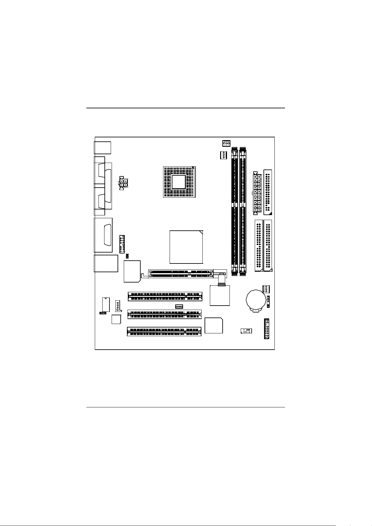
GA-8IRM Series Motherboard Layout
KB_MS
COMA
COMB
LINE_OUTMIC_IN
LINE_IN
USB/
LAN_EN*
LPT
GAME
LAN*
82562ET*
AC97
F_AUDIO
CD_IN
AUX_12V
CI
W83627HF
AGP
SOCKET478
GA-8IRM(L)
Brookdale
WOL
PCI1
PCI2
PCI3
CPU_FAN
PWR_FAN
ICH2
FWH
DDR1
DDR2
F_USB
BATTERY
ATX
IDE2
FDD
IDE1
SYS _FAN
IR
F_PANEL
* For GA-8IRML only.
8
Page 13
Hardware Installation Process
Chapter 2 Hardware Installation Process
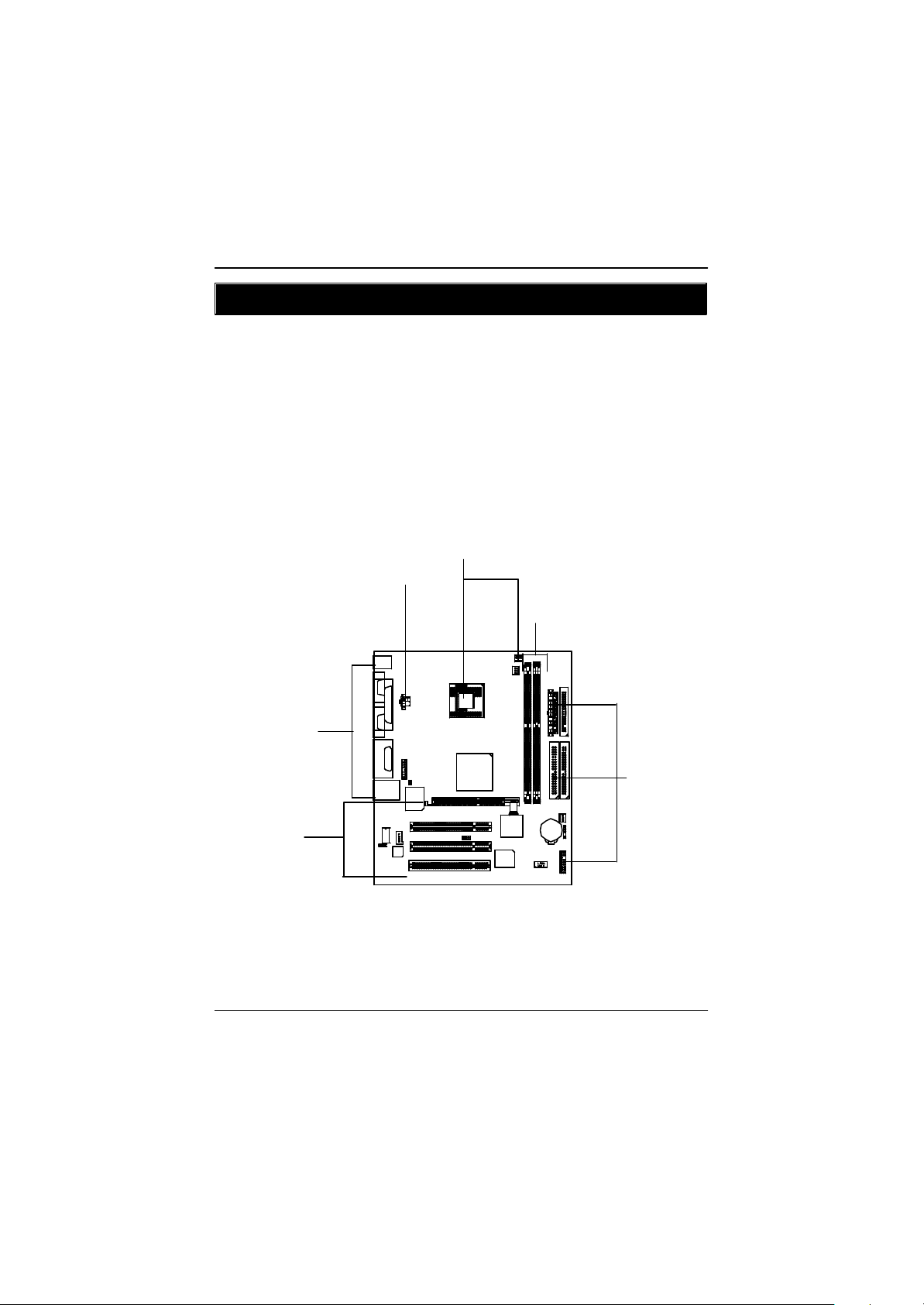
To set up your computer, you must complete the following steps:
Step 1- Install the Central Processing Unit (CPU)
Step 2- Install memory modules
Step 3- Install expansion cards
Step 4- Connect ribbon cables, cabinet wires, and power supply
Step 5- Setup BIOS software
Step 6- Install supporting software tools
Step1
Step4
Step 2
Step 4
Step3
Step 4
9
Page 14
GA-8IRM Series Motherboard
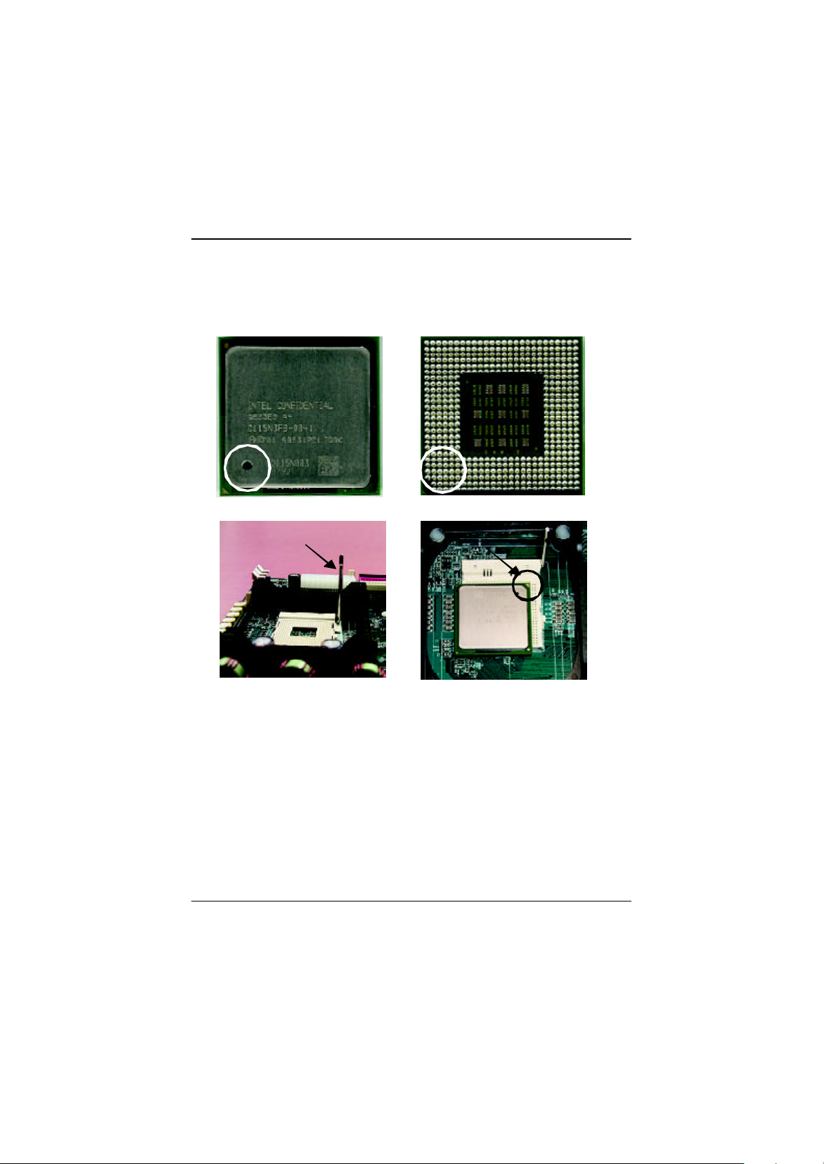
Step 1: Install the Central Processing Unit (CPU)
CPU Installation
Pin1 indicator Pin1 indicator
CPU Top View CPU Bottom View
Socket Actuation Lever
1. Pull up the CPU socket lever
and up to 90-degree angle.
3. Press down the CPU socket
lever and finish CPU installation.
? Please make sure the CPU type is supported by the motherboard.
? If you do not match the CPU socket Pin 1 and CPU cut edge well, it will cause
improper installation. Please change the insert orientation.
10
Pin1 indicator
2. Locate Pin 1 in the socket and look
for a (golden) cut edge on the CPU
upper corner. Then insert the CPU
into the socket.
Page 15
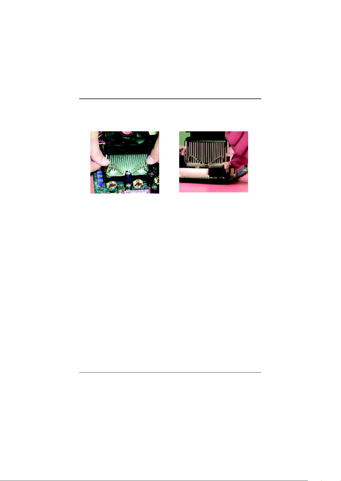
CPU Heat Sink Installation
Hardware Installation Process
1. Hook one end of the cooler
bracket to the CPU socket first.
2. Hook the other end of the
cooler bracket to the CPU
socket.
? Please use Intel approved cooling fan.
? We recommend you to apply the thermal tape to provide better heat
conduction between your CPU and heatsink.
(The CPU cooling fan might stick to the CPU due to the hardening of the
thermal paste. During this condition if you try to remove the cooling fan, you
might pull the processor out of the CPU socket alone with the cooling fan, and
might damage the processor. To avoid this from happening, we suggest you to
either use thermal tape instead of thermal paste, or remove the cooling fan with
extreme caution.)
? Make sure the CPU fan power cable is plugged in to the CPU fan connector,
this completes the installation.
? Please refer to CPU heat sink user’s manual for more detail installation
procedure.
11
Page 16

GA-8IRM Series Motherboard
Step 2: Install memory modules
The motherboard has 2 dual inline memory module (DIMM) sockets. The BIOS w ill automatic ally
detects memory type and size. To install the memory module, just push it vertically into the DIMM Slot
.The DIMM module can only fit in one direction due to the notch. Memory size can vary between
sockets.
Total Memory Sizes With Unbuffered DDR DIMM
Dev ices used on DIMM 1 DIMM x 64 / x 72 2 DIMMs x 64 / x 72
64 Mbit (2Mx 8x 4 banks) 128 MBy tes 256 MBy tes
64 Mbit (1Mx 16x 4 banks) 32 MBy tes 64 MBy tes
128 Mbit(4Mx 8x 4 banks) 256 MBy tes 512 MBy tes
128 Mbit(2Mx 16x 4 banks) 64 MBy tes 128 MBy tes
256 Mbit(8Mx 8x 4 banks) 512 MBy tes 1 GBy tes
256 Mbit(4Mx 16x 4 banks) 128 MBy tes 256 MBy tes
512 Mbit(16Mx 8x 4 banks) 1 GBy tes 2 GBy tes
512 Mbit(8Mx 16x 4 banks) 256 MBy tes 512 MBy tes
Notes: Double-sided x 16 DDR memory dev ic es are not support by Intel 845 c hipset.
DDR
1. The DIMM slot has a notch, so the
DIMMmemory module can only fit in one direction.
2. Insert the DIMM memory module verticallyinto the
DIMM slot. Then push it down.
3. Close the plastic clip at both edges of theDIMM slots
to lock the DIMM module.
Reverse the installation steps when you wish to
remove the DIMM module.
? When STR/DIMM LED is ON, you do not install / remove DDR from socket.
12
Page 17

Hardware Installation Process
DDR Introduction
Established on the existing SDRAM industry infrastructure, DDR (Double Data Rate) memory is a
high performance and cost-effective solution that allows easy adoption for memory vendors, OEMs and
system integrators.
DDR memory is a sensible evolutionary solution for the PC industry that builds on the existing
SDRAM infrastructure, yet makes awesome advances in solving the system performance bottleneck by
doubling the memory bandwidth. DDR SDRAM w ill offer a superior so lution and m igration path from
existing SDRAM designs due to its availability, pricing and overall market support. PC2100 DDR
memory (DDR266) doubles the data rate through reading and writing at both the rising and falling edge of
the clock, achieving data bandwidth 2X greater than PC133 when running with the same DRAM clock
frequency. With peak bandwidth of 2.1GB per second, DDR memory enables system OEMs to build
high performance and low latency DRAM subsystems that are suitable for servers, workstations, highend PC 's a nd v alue des ktop SM A sy stems. With a core voltage of only 2.5 Volts c ompa red to
conventional SDRAM's 3.3 volts, DDR memory is a compelling solution for small form factor desktops
and notebook applications.
Step 3: Install expansion cards
1. Read the related expansion card’s instruction document before install the expansion card into
the computer.
2. Remove your computer’s chassis cover, necessary screws and slot bracket from the computer.
3. Press the expansion card firmly into expansion slot in motherboard.
4. Be sure the metal contacts on the card are indeed seated in the slot.
5. Replace the screw to secure the slot bracket of the expansion card.
6. Replace your computer’s chassis cover.
7. Power on the computer, if necessary, setup BIOS utility of expansion card from BIOS.
8. Install related driver from the operating system.
AGP Card
Please carefully pull out the small whitedrawable bar at the end of the AGP slot when
you try to install/ Uninstall the AGP card.
Please align the AGP card to the onboard
AGP slot and press firmly down on the slot .
Make sure your AGP card is locked by the
small white- drawable bar.
13
Page 18

GA-8IRM Series Motherboard
Step 4: Connect ribbon cables, cabinet wires, and power
supply
I/O Back Panel Introduction
?
? ?
? PS/2 Keyboard and PS/2 Mouse Connector
PS/2 Mouse Connector
(6 pin Female)
PS/2 Keyboard Connector
(6 pin Female)
?This connector supports standard PS/2
keyboard and PS/2 mouse.
? Parallel Port and Serial Ports (COM1/COM2)
Parallel Port
(25 pin Female)
?This connector supports 2 standard COM ports
and 1 Parallel port. Device like printer can be
connected to Parallel port ; mouse and modem
etc can be connected to Serial ports.
?
?
COMA COMB
Serial Ports (9 pin Male)
14
Page 19

? Game /MIDI Ports
Joystick/ MIDI (15 pin Female)
? Audio Connectors
Hardware Installation Process
?This connector supports joystick, MIDI keyboard and other
relate audio devices.
? After install onboard audio driver, you may connect
speaker to Line Out jack, micro phone to MIC In jack.
Device like CD-ROM , walkman etc can be connected
to Line-In jack.
Line Out
MIC In
Line In
? USB/LAN Connector
LAN*
Connector
USB 0
USB 1
* For GA-8IRML only.
?Before you connect your device(s) into USB connector(s),
please make sure your device(s) such as USB keyboard,
mouse, scanner, zip,speaker..etc. Have a standard USB
interface. Also make sure your OS (Win 95 with USB
supplement, Win98, Windows 2000, Windows ME, Win
NT with SP 6) supports USB controller. If your OS does not
support USB controller, please contact OS vendor for pos-
sible patch or driver upgrade. For more information please
contact your OS or device(s) vendors.
15
Page 20

GA-8IRM Series Motherboard
Connectors Introduction
A B
C
D
E
P
O
N
M
A) AUX_12V
B) CPU_FAN
C) PWR_FAN
D) ATX
E) FDD
F) IDE1/IDE2
G) BATTERY
H) SYS_FAN
F
G
H
I
J
L
K
I) IR
J) F_PANEL
K) FP_USB
L) WOL
M) LAN_EN*
N) CD_IN
O) CI
P) F_AUDIO
* For GA-8IRML only.
16
Page 21

Hardware Installation Process
A) AUX_12V ( +12V Power Connector)
4
2
+12V GND
+12V GND
3
1
B ) CPU_FAN (CPU FAN Connector)
Sense
GND
+12V/Control
1
C ) PWR_FAN (Power FAN Connector)
Sense
1
+12V/Control
GND
?This connector (ATX +12V) suppliesthe CPU
operation voltage (Vcore).
If this " ATX+ 12V connector" is not connected,
system cannot boot.
? Please note, a proper installation of the CPU
cooler is essential to prevent the CPU from
running under abnormal condition or damaged
by overheating.The CPU fan connector
supports Max. current up to 600 mA.
H ) SYS_FAN (System FAN Connector)
1
GND
+12V/Control
Sense
O) CI (CASE OPEN)
1
? This 2 pin connector allows your system to
enable or disable the system alarm if the sys
tem case begin remove.
GND
Signal
17
Page 22

GA-8IRM Series Motherboard
E ) FDD (Floppy Connector)
1
F ) IDE1/ IDE2 (IDE1/IDE2 Connector)
1
IDE1
1
IDE2
K) F_USB (Front USB Connector)
GND
USB 3-
USB 3+
Power
1
? Important Notice:
Please connect first harddisk to IDE1
and connect CDROM to IDE2.
? Be careful with the polarity of the front
panel USB connector. Check the pin
assignment while you connect the front
panel USB cable. Please contact your
nearest dealer for optional front panel
USB cable.
Power
USB 2-
GND
USB 2+
18
Page 23

N) CD_IN1 (CD IN)
CD-R
GND
1
CD_IN
CD-L
Hardware Installation Process
I)IR
IR Data Output
GND
IR Data Input
1
VCC(+5V)
P) F_AUDIO (Front Audio Connector)
Rear Audio (L)
Rear Audio (R)
GND
Incase speaker (L)
GND
GND
GND
Front Audio (R)
+12V
GND
1
?Be careful with the polarity of the IR
connectorwhile you connect the IR. Please
contact you nearest dealer for optional IR
device.
Front Audio (L)
MIC
GND
Incase speaker (R)
? If you want to use "Front Audio" connector,
you must move 11-12,13-14 Jumper. In order to
utilize the front audio header, your chassis must
have front audio connector. Also please make
sure the pin assigment on the cable is the same
as the pin assigment on the MB header. To find
out if the chassis you are buying support front
audio connector, please contact your dealer.
19
Page 24

GA-8IRM Series Motherboard
L) WOL (Wake on LAN)
1
+5V SB
GND
Signal
M) LAN_EN (Onboard LAN Function)*
1
1-2 close: Enable(Default)
2-3 close: Disable
1
D ) ATX (ATX Power)
20
5V SB (Stand by +5V)
+12V
Power Good
GND
VCC
GND
VCC
GND
3.3V
3.3V
1
?This MB supports optional LAN chip.If the MB
has optional LAN chip the user can enable the
LAN function by setting the “LAN_EN” to 1-2,
user can disable the optional LAN function by
setting the “LEN_EN” to 2-3. “LEN_EN” will
have any effect if the board does not have
optioal LAN chip.
?AC power cord should only be connected to
your power supply unit after ATX power cable
VCC
VCC
-5V
GND
GND
GND
PS-ON(Soft On/Off)
GND
-12V
3.3V
and other related devices are firmly
connected to the mainboard.
* For GA-8IRML only.
20
Page 25

J) F_PANEL (2x7 pins jumper)
13
RSTRST+
SPK+
1
SPK-
HD-
HD (IDE Hard Disk Active LED) Pin 1: LED anode(+)
SPK (Speaker Connector) Pin 1: VCC(+)
RST (Reset Switch) Open: Normal Operation
PD+/PD_G-/PD_Y-(Power LED) Pin 1: LED anode(+)
PW (Soft Power Connector) Open: Normal Operation
PW+
PW-
PD+
PD_GPD_Y-
1
HD+
1
2 14
Pin 2: LED cathode(-)
Pin 2- Pin 3: NC
Pin 4: Data(-)
Close: Reset Hardware System
Pin 2: LED cathode(-)
Pin 3: LED cathode(-)
Close: Power On/Off
Hardware Installation Process
? Please connect the power LED, PC speaker, reset switch and power switch etc of your chassis
front panel to the F_PANEL connector according to the pin assignment above.
G) Battery
? Danger of explosion if battery is incorrectly
+
replaced.
? Replace only with the same or equivalent
type recommended by the manufacturer.
? Dispose of used batteries according to the
manufacturer’s instructions.
21
CAUTION
Page 26

Technical Reference
Revision History
Chapter 4 Technical Reference
Performance List
The following performance data list is the testing results of some popular benchmark testing programs.
These data are just referred by users, and there is no responsibility for different testing data values
gotten by users. (The different Hardware & Software configuration will result in different benchmark
testing results.)
CPU Intel Pentuim
DDR RAM (128 x 2) MB RAM (NANYA NT5DS16M8AT-7K S)
CACHE SIZE 256KB included in CPU
DISPLAY Gigabyte GV-GF3000D (NUCD 1.9)
STORAGE Onboard IDE (Quantum AS30000AT 30GB)
O.S Windows 2000+ SP2+DX 8.0a
DRIVER Display Driver at 1024 x 768 x 64K colors x 75Hz
IUCD ver. 1.9 For Intel chipset M.B.
Pr ocessor Intel Pentium® 4
2GHz (100x20)
WCPUID 3.0D Clock Fr equency
Internal MHz 2019.88
External MHz 100.99
SiSoft Sandr a 2001
CPU/FPU Benchmark 3895/2484
CPU Multi-Media Benchmark 8025/9945
Drives Benchmark 20663
Memory Benchmark 1015/1073
SPECviewper f 6. 12
Pro CDRS-03 14.76
MedMCAD-01 30.19
Light-04 8.283
DX-06 27.13
DRV-07 18.18
Awadvs-04 62.11
QUAKE III Ar ena (wi thout sound)
640*480*16 Demo1 199.2
1024*768*32 Demo2 181.2
3D Mar k 2001 1.0 6852
®
4 2GHz processor
57
Page 27

GA-8IRM Series Motherboard
Block Diagram
AGPCLK
(66MHz)
3 PCI
PCICLK
(33MHz)
AGP 4X
RJ45*
Intel 82562ET*
AC97
CODEC
Pentium 4
CPU
82845
AC97 Link
4 USB
Ports
System Bus 100MHz
100/133 MHz
Intel
48 MHz
Intel
ICH 2
LPC BUS
ATA33/66/100
IDE Channels
CPUCLK6 ( 100 MH z)
HCLK6 ( 100 MH z)
MCHCLK (66MHz)
66 MHz
33 MHz
14.318 MHz
Winbond
83627
24 MHz
33 MHz
DDR RAM
FWH
Game Port
Floppy
LPT Port
PS/2
KB/Mouse
COM
Ports
PCICLK (33MHz)
USBCLK (48MHz)
14.318 MHz
33 MHz
* For GA-8IRML only .
MIC
LINE-IN
LINE-OUT
CLK
GEN
58
HCLK6 ( 100 MH z)
CPUCLK6 ( 100 MH z)
AGPCLK (66MHz)
MCHCLK (66MHz)
ICH3V66 (66MHz)
Page 28

Technical Reference
@ BIOS Introduction
Gigabyte announces @ BIOS
Windows BIOS live update utility
Have you ever updated BIOS by yourself? Or like
many other people, you just know what BIOS is,
but always hesitate to update it? Because you think
updating newest BIOS is unnecessary and actually
you don’t know how to update it.
Maybe not like others, you are very experienced in BIOS updating and spend quite a lot of time
to do it. But of course you don’t like to do it too much. First, download different BIOS from website and
then switch the operating system to DOS mode. Secondly, use different flash utility to update BIOS.
The above process is not a interesting job. Besides, always be carefully to store the BIOS source
code correctly in your disks as if you update the wrong BIOS, it will be a nightmare.
Certainly, you wonder why motherboard vendors could not just do something right to save your
time and effort and save you from the lousy BIOS updating work? Here it comes! Now Gigabyte
announces @BIOS— the first Windows BIOS live update utility. This is a smart BIOS update
software. It could help you to download the BIOS from internetand update it. Not like the other BIOS
update software, it’s a Windows utility. With the help of “@BIOS’, BIOS updating is no more than a
click.
Besides, no matter which mainboard you are using, if it’s a Gigabyte’s product*, @BIOS help
you to maintain the BIOS. This utility could detect your correct mainboard model and help you to
choose the BIOS accordingly. It then downloads the BIOS from the nearest Gigabyte ftp site
automatically. There are several different choices; you could use “Internet Update” to download and
update your BIOS directly. Or you may want to keep a backup for your current BIOS, just choose
“Save Current BIOS” to save it first. You make a wise choice to use Gigabyte, and @BIOS update
your BIOS smartly. You are now worry free from updating wrong BIOS, and capable to maintain and
manage your BIOS easily. Again, Gigabyte’s innovative product erects a milestone in mainboard
industries.
For such a wonderful software, how much it costs? Impossible! It’s free! Now, if you buy a
Gigabyte’s motherboard, you could find this amazing software in the attached driver CD. But please
remember, connected to internet at first, then you could have a internet BIOS update from your
Gigabyte @BIOS.
59
Page 29

GA-8IRM Series Motherboard
Easy TuneIIITM Introduction
Gigabyte announces EasyTuneIII
Windows overdrive utility
“Overdrive” might be one of the most
common issues in computer field. But have many
users ever tried it? The answer is probably “no”.
Because “overdrive” is thought to be very difficult and
includes a lot of technical know-how, sometimes “over-
drive” is even considered as special skills found only in some enthusiasts.
But as to the experts in “overdrive”, what’s the truth? They may spend quite a lot of time and money
to study, try and use many different hardware and software tools to do “overdrive”. And even with these
technologies, they still learn that it’s quite a risk because the safety and stability of an “overdrive“ system
is unknown.
Now everything is different because of a Windows overdrive utility EasyTuneIII— announced by
Gigabyte. This utility has totally changed the gaming rule of “overdrive”. This is the first overdrive utility
suitable for both normal and power users. Users can choose either “Easy Mode” or “Advanced Mode”
to run “overdrive” at their convenience. For users who choose “Easy Mode”, they just need to click
“Auto Optimize” to have auto and immediate CPU overclocking. This software will then overdrive CPU
speed automatically with the result being shown in the control panel. If someone prefers to “overdrive” by
oneself, there is also another choice. Click “Advanced Mode” to enjoy “sport drive” class overclocking.
In “Advanced Mode”, one can change the system bus speed in small increments to get ultimate system
performance. And no matter which mainboard is used, if it’s a Gigabyte’s product*, EasyTuneIII helps to
perform the best of system.
Besides, different from other traditional over-clocking methods, EasyTuneIII doesn’t require users to
change neither BIOS nor hardware switch/ jumper setting; on the other hand, they can do “overdrive” at
only one click. Therefore, this is a safer way for “overdrive” as nothing is changed on software or
hardware. If user runs EasyTuneIII over system’s limitation, the biggest lost is only to restart the
computer again and the side effect is then well controlled. Moreover, if one well-performed system speed
been tested in EasyTuneIII, user can “Save” this bus speed and “Load” it in next time. Obviously,
Gigabyte EasyTuneIII has already turned the “overdrive” technology toward to a newer generation.
This wonderful software is now free bundled in Gigabyte motherboard attached driver CD. Users
may make a test drive of “EasyTuneIII” to find out more amazing features by themselves.
60
Page 30

Appendix
Revision History
Chapter 5 Appendix
Picture below are shown in Windows ME (IUCD driver version 1.9)
Insert the driver CD-title that came with your motherboard into your CD-ROM driver, the driver
CD-title will auto start and show the installation guide. If not, please double click the CD-ROM device
icon in "My computer", and execute the setup.exe.
A. Installing Intel 845 Chipset Driver
Please install this driver as the first
priority. this item installs the chipset
driver utility that enableds Plug-nPlag INF support for Intel chipset
component.
B. Installing Sound Driver
Click this item to install sound
driver.
C. Installing LAN Driver*
Click this item to install LAN
driver.
Appendix A: Intel 845 Chipset Driver Installation
Follow the setup that showing on the scween to install the Utility.
A-2.Click "Intel Ultra ATA Storage
Driver" item.
* For GA-8IRML Only.
A-1.Click "Windows 9x/ME/2000/XP
INF Update Utility" item.
61
Page 31

GA-8IRM Series Motherboard
Appendix B: RealTek AC’97 Audio Driver
Press "Audio" icon.
1.Click " RealTek AC’97 Audio Driver"
item.
Appendix C: Intel 82562 Network Driver*
"Intel 82562 Network Driver" under Windows ME will auto install. If you would like to
install LAN driver, please refer to attached README.txt file for detail instruction. Please install the
driver through CD-ROM by the path D:\Network\Rtl (This manual assumes that your CD-ROM
device drive letter is D:).
Press "Network" icon.
Click "Driver Information".
Revision History
Appendix D:
(*For GA-8IRML Only)
1.EasyTuneIII Utilities Installation
Press "Tools" icon.
2.Click "Easy Tune III Setup".
1.Click "Gigabyte Utilities".
62
Page 32

Appendix
Appendix E: BIOS Flash Procedure
BIOS update procedure:
If your OS is Win9X, we recommend that you used Gigabyte @BIOSTM Program to flash BIOS.
2.Click "@BIOS Writer Utility
Press "Tools" icon.
1.Click "Gigabyte Utilities".
(1) (2)
v1.08e".
Click "?".
Click here.
(3)
Methods and steps:
I. Update BIOS through Internet
a. Click "Internet Update" icon
b. Click "Update New BIOS" icon
c. Select @BIOSTM sever ("Gigabyte @BIOSTM sever 1 in Taiwan" and "Gigabyte
@BIOSTM sever 2 in Taiwan" are available for now, the others will be completedsoon)
d. Select the exact model name on your motherboard
e. System will automatically download and update the BIOS.
63
Page 33

GA-8IRM Series Motherboard
II. Update BIOS NOT through Internet:
a. Do not click "Internet Update" icon
b. Click "Update New BIOS"
c. Please select "All Files" in dialog box while opening the old file.
d. Please search for BIOS unzip file, downloading from internet or any other methods (such as:
8IRX.F1).
e. Complete update process following the instruction.
III. Save BIOS
In the very beginning, there is "Save Current BIOS" icon shown in dialog box. It means to save
the current BIOS version.
IV. Check out supported motherboard and Flash ROM:
In the very beginning, there is "About this program" icon shown in dialog box. It can help you
check out which kind of motherboard and which brand of Flash ROM are supported.
Note:
a. In method I, if it shows two or more motherboard's model names to be selected, please make
sure your motherboard's model name again. Selecting wrong model name will cause the
system unbooted.
b. In method II, be sure that motherboard's model name in BIOS unzip file are the same as your
motherboard's. Otherwise, your system won't boot.
c. In method I, if the BIOS file you need cannot be found in @BIOSTM server, please go onto
Gigabyte's web site for downloading and updating it according to method II.
d. Please note that any interruption during updating will cause system unbooted
64
Page 34

Appendix
We use GA-7VTX motherboard and Flash841 BIOS flash utility as example.
Please flash the BIOS according to the following procedures if you are now under the DOS mode.
Flash BIOS Procedure:
STEP 1:
(1) Please make sure you have set "Auto" for BIOS Feature Setup (BIOS Flash Protection). For
more detail please refer to page 32.
(2) Please make sure your system has installed the extraction utility such as winzip or pkunzip.
Firstly you have to install the extraction utility such as winzip or pkunzip for unzip the files. Both of
these utilities are available on many shareware download pages like http://www.shareware.cnet.
com
STEP 2: Make a DOS boot diskette. (See example: Windows 98 O.S.)
Beware: Windows ME/2000 are not allowed to make a DOS boot diskette.
(1) With an available floppy disk in the floppy drive. Please leave the diskette "UN-write protected"
type. Double click the "My Computer" icon from Desktop, then click "3.5 diskette (A)" and right
click to select "Format (M)"
65
Page 35

GA-8IRM Series Motherboard
(2) Select the "Quick (erase)" for Format Type, and pick both "Display summary when finished" and
"Copy system files", after that press "Start". That will format the floppy and transfer the needed
system files to it.
Beware: This procedure will erase all the prior data on that floppy, so please proceed accordingly.
(3) After the floppy has been formatted completely, please press "Close".
66
Page 36

Appendix
STEP 3: Download BIOS and BIOS utility program.
(1) Please go to Gigabyte website http://www.gigabyte.com.tw/index.html, and click "Support".
(2) From Support zone, click the "Motherboards BIOS & Drivers".
67
Page 37

GA-8IRM Series Motherboard
(3) We use GA-7VTX motherboard as example. Please select GA-7VTX by Model or Chipset
optional menu to obtain BIOS flash files.
(4) Select an appropriate BIOS version (For example: F4), and click to download the file. It will pop
up a file download screen, then select the "Open this file from its current location" and press "OK".
68
Page 38

Appendix
(5) At this time the screen shows the following picture, please click "Extract" button to unzip the files.
(6) Please extract the download files into the clean bootable floppy disk A mentioned in STEP 2, and
press "Extract".
69
Page 39

GA-8IRM Series Motherboard
STEP 4: Make sure the system will boot from the floppy disk.
(1) Insert the floppy disk (contains bootable program and unzip file) into the floppy drive A. Then,
restart the system. The system will boot from the floppy disk. Please press <DEL> key to enter
BIOS setup main menu when system is boot up.
(2) Once you enter the BIOS setup utility, the main menu will appear on the screen. Use the arrows
to highlight the item "BIOS FEATURES SETUP".
AMIBIOS SIMPLE SETUP UTILITY - VERSION 1.24b
(C) 1999 American Megatrends, Inc. All Rights Reserved
STANDARD CMOS SETUP INTEGRATED PERIPHERALS
BIOS FEATURES SETUP HARDWARE MONITOR & MISC SETUP
CHIPSET FEATURES SETUP SUPERVISOR PASSWORD
POWER MANAGEMENT SETUP USER PASSWORD
PNP / PCI CONFIGURATION IDE HDD AUTO DETECTION
LOAD BIOS DEFAULTS SAVE & EXIT SETUP
LOAD SETUP DEFAULTS EXIT WITHOUT SAVING
ESC: Quit ????? : Select Item (Shift)F2 : Change Color F5: Old Values
F6: Load BIOS Defaults F7: Load Setup Defaults F10:Save & Exit
Time, Date , Hard Disk Type…
70
Page 40

Appendix
(3) Press "Enter" to enter "BIOS FEATURES SETUP" menu. Use the arrows to highlight the item
"1st Boot Device", and then use the "Page Up" or "Page Down" keys to select "Floppy".
AMIBIOS SETUP - BIOS FEATURES SETUP
( C ) 2001 American Megatrends, Inc. All Rights Reserved
1st Boot Device : Floppy
2nd Boot Device : IDE-0
3rd Boot Device : CDROM
S.M.A.R.T. for Hard Disks : Disabled
BootUp Num-Lock : On ESC: Quit ????: Select Item
Floppy Drive Seek : Disabled F1 : Help PU/PD/+/- : Modify
Password Check : Setup F5 : Old Values (Shift)F2: Color
F6 : Load BIOS Defaults
F7 : Load Setup Defaults
(4) Press "ESC" to go back to previous screen. Use the arrows to highlight the item "SAVE & EXIT
SETUP" then press "Enter". System will ask "SAVE to CMOS and EXIT (Y/N)?" Press "Y"
and "Enter" keys to confirm. Now the system will reboot automatically, the new BIOS setting
will be taken effect next boot-up.
AMIBIOS SIMPLE SETUP UTILITY - VERSION 1.24b
(C) 2001 American Megatrends, Inc. All Rights Reserved
STANDARD CMOS SETUP INTEGRATED PERIPHERALS
BIOS FEATURES SETUP HARDWARE MONITOR & MISC SETUP
CHIPSET FEATURES SETUP SUPERVISOR PASSWORD
POWER MANAGEMENT SETUP USER PASSWORD
PNP / PCI CONFIGURATION IDE HDD AUTO DETECTION
LOAD BIOS DEFAULTS SAVE & EXIT SETUP
LOAD SETUP DEFAULTS EXIT WITHOUT SAVING
ESC: Quit ????? : Select Item (Shift)F2 : Change Color F5: Old Values
F6: Load BIOS Defaults F7: Load Setup Defaults F10:Save & Exit
Save to CMOS and EXIT (Y/N)? Y
Save Data to CMOS & Exit SETUP
71
Page 41

GA-8IRM Series Motherboard
STEP 5: BIOS flashing.
(1) After the system boot from floppy disk, type "A:\> dir/w" and press "Enter" to check the entire
files in floppy A. Then type the "BIOS flash utility" and "BIOS file" after A:\>. In this case you
have to type "A:\> Flash841 7VTX.F4" and then press "Enter".
Starting Windows 98…
Microsoft(R) Windows98
© Copyright Microsoft Corp 1981-1999
A:\> dir/w
Volume in drive A has no label
Volume Serial Number is 16EB-353D
Directory of A:\
COMMAND.COM 7VTX.F4 FLASH841.EXE
3 file(s) 838,954 bytes
0 dir(s) 324,608 bytes free
A:\> Flash841 7VTX.F4
(2) Now screen appears the following Flash Utility main menu. Press "Enter", the highlighted item
will locate on the model name of the right-upper screen. Right after that, press "Enter" to start
BIOS Flash Utility.
72
Page 42

Appendix
(3) It will pop up a screen and asks "Are you sure to flash the BIOS?" Press [Enter] to continue the
procedure, or press [ESC] to quit.
Beware: Please do not turn off the system while you are upgrading BIOS. It will render your
BIOS corrupted and system totally inoperative.
Are you sure to flash the BIOS?
[Enter] to continue Or [Esc] to cancel?
(4) The BIOS flash completed. Please press [ESC] to exit Flash Utility.
EXIT?
[Enter] to continue Or [Esc] to cancel?
73
Page 43

GA-8IRM Series Motherboard
STEP 6: Load BIOS defaults.
Normally the system redetects all devices after BIOS has been upgraded. Therefore, we highly
recommend reloading the BIOS defaults after BIOS has been upgraded. This important step
resets everything after the flash.
(1) Take out the floppy diskette from floppy drive, and then restart the system. The boot up screen will
indicate your motherboard model and current BIOS version.
(2) Don't forget to press <DEL> key to enter BIOS setup again when system is boot up. Use the
arrows to highlight the item "LOAD SETUP DEFAULTS" then press "Enter". System will ask
"Load Setup Defaults (Y/N)?" Press "Y" and "Enter" keys to confirm.
AMIBIOS SIMPLE SETUP UTILITY - VERSION 1.24b
(C) 2001 American Megatrends, Inc. All Rights Reserved
STANDARD CMOS SETUP INTEGRATED PERIPHERALS
BIOS FEATURES SETUP HARDWARE MONITOR & MISC SETUP
CHIPSET FEATURES SETUP SUPERVISOR PASSWORD
POWER MANAGEMENT SETUP USER PASSWORD
PNP / PCI CONFIGURATION IDE HDD AUTO DETECTION
LOAD BIOS DEFAULTS SAVE & EXIT SETUP
LOAD SETUP DEFAULTS EXIT WITHOUT SAVING
ESC: Quit ????? : Select Item (Shift)F2 : Change Color F5: Old Values
F6: Load BIOS Defaults F7: Load Setup Defaults F10:Save & Exit
Load Setup Defaults? (Y/N)?N
Load Setup Defaults
74
Page 44

Appendix
(3) Use the arrows to highlight the item "SAVE & EXIT SETUP" and press "Enter". System will
ask "SAVE to CMOS and EXIT (Y/N)?" Press "Y" and "Enter" keys to confirm. Now the
system will reboot automatically, the new BIOS setting will be taken effect next boot-up.
AMIBIOS SIMPLE SETUP UTILITY - VERSION 1.24b
(C) 2001 American Megatrends, Inc. All Rights Reserved
STANDARD CMOS SETUP INTEGRATED PERIPHERALS
BIOS FEATURES SETUP HARDWARE MONITOR & MISC SETUP
CHIPSET FEATURES SETUP SUPERVISOR PASSWORD
POWER MANAGEMENT SETUP USER PASSWORD
PNP / PCI CONFIGURATION IDE HDD AUTO DETECTION
LOAD BIOS DEFAULTS SAVE & EXIT SETUP
LOAD SETUP DEFAULTS EXIT WITHOUT SAVING
ESC: Quit ????? : Select Item (Shift)F2 : Change Color F5: Old Values
F6: Load BIOS Defaults F7: Load Setup Defaults F10:Save & Exit
Save to CMOS and EXIT (Y/N)? Y
Save Data to CMOS & Exit SETUP
(4) Congratulate you have accomplished the BIOS flash procedure.
75
Page 45

GA-8IRM Series Motherboard
Appendix G: Acronyms
Acronyms Meaning
ACPI Advanced Configuration and Power Interface
APM Advanced Power Management
AGP Accelerated Graphics Port
AMR Audio Modem Riser
ACR Advanced Communications Riser
BIOS Basic Input / Output System
CPU Central Processing Unit
CMOS Complementary Metal Oxide Semiconductor
CRIMM Continuity RIMM
CNR Communication and Networking Riser
DMA Direct Memory Access
DMI Desktop Management Interface
DIMM Dual Inline Memory Module
DRM Dual Retention Mechanism
DRAM Dynamic Random Access Memory
DDR Double Data Rate
ECP Extended Capabilities Port
ESCD Extended System Configuration Data
ECC Error Checking and Correcting
EMC Electromagnetic Compatibility
EPP Enhanced Parallel Port
ESD Electrostatic Discharge
FDD Floppy Disk Device
FSB Front Side Bus
HDD Hard Disk Device
IDE Integrated Dual Channel Enhanced
IRQ Interrupt Request
I/O Input / Output
IOAPIC Input Output Advanced Programmable Input Controller
ISA Industry Standard Architecture
LAN Local Area Network
to be continued......
76
Page 46

Acronyms Meaning
LBA Logical Block Addressing
LED Light Emitting Diode
MHz Megahertz
MIDI Musical Interface Digital Interface
MTH Memory Translator Hub
MPT Memory Protocol Translator
NIC Network Interface Card
OS Operating System
OEM Original Equipment Manufacturer
PAC PCI A.G.P. Controller
POST Power-On Self Test
PCI Peripheral Component Interconnect
RIMM Rambus in-line Memory Module
SCI Special Circumstance Instructions
SECC Single Edge Contact Cartridge
SRAM Static Random Access Memory
SMP Symmetric Multi-Processing
SMI System Management Interrupt
USB Universal Serial Bus
VID Voltage ID
Appendix
77
Page 47

GA-8IRM Series Motherboard
?
Technical Support/RMA Sheet
Customer/Country: Company: Phone No.:
Contact Person: E-mail Add. :
Model name/Lot Number: PCB revision:
BIOS version: O.S./A.S.:
Hardware Mfs. Model name Size: Driver/Utility:
Configuration
CPU
Memory
Brand
Video Card
Audio Card
HDD
CD-ROM /
DVD-ROM
Modem
Network
AMR / CNR
Keyboard
Mouse
Power supply
Other Device
Problem Description:
?
78
 Loading...