

Page 1
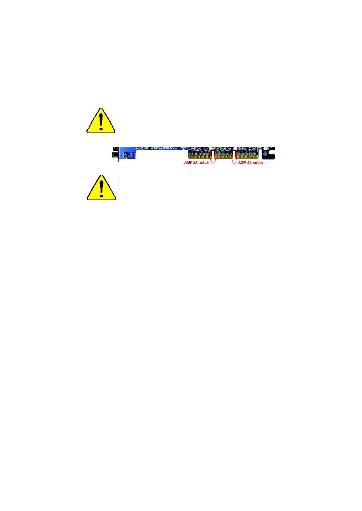
When you installing AGP card, please make sure the follow
ing notice is fully understood and practiced. If your AGP
card has "AGP 4X notch"(show below), please make sure
your AGP card is AGP 4X (1.5V).
Do not use AGP 2X card (3.3V) in this motherboard. It will
burn and damage the motherboard due to Intel® 845
/ Intel® 850 chipset can't support AGP 2X(3.3V).
Example 1: Diamond Vipper V770 golden finger is compatible with 2X/
4X mode AGP slot. It can be switched between AGP 2X (3.3V) or 4X
(1.5V) m ode by adjusting the jumper. The factory default for this card is
2X(3.3V). If you install this card in GA-8IRE (or any AGP 4X only)
motherboards without switching the jumper to 4X mode (1.5V), it will
burn the motherboard.
Example 2: Some A Ti Rage 128 Pro graphics cards made by “Power
Color”, the graphics card manufacturer & some SiS 305 cards, their
golden finger is compatible with 2X/4X mode AGP slot, but they support
2X (3.3V) only. If you install these cards in Intel® 845 / Intel® 850 based
motherboards, they will burn the m otherboard.
Note : Although Gigabyte's AG32S graphics card is based on A Ti Rage
128 Pro chip, the design of AG32S is compliance with AGP 4X ( 1.5V)
specification. Therefore, AG32S will wor k fine with Intel® 845 /
Intel® 850 based motherboards.
Page 2
M
The author assumes no responsibility for any errors or omissions
that may appear in this document nor does the author make a
comm itment to update the information contained herein.
M
Thi rd-party brands and names are the property of their respective
owners.
M
Please do not remove any labels on motherboard, thismay void the
warr anty of this motherboard.
M
Due to rapid change in technology, some of the specifications might
be out of date before publication of this booklet.
Page 3

Ausschlager Weg 41, 1F, 20537 Hamburg, Germany
( description of the apparatus, system, installation to which it refers)
(reference to the specification under which conformity is declared)
in accordance with 89/336 EEC-EMC Directive
EN 55011 Limits and methods of measurement
EN 55013
EN 55014 Limits and methods of measurement
EN 55015 Limits and methods of measurement
EN 55020
77
7 EN 55022 Limits and methods of measurement
77
DIN VDE 0855
part 10
part 12
77
7 CE marking
77
EN 60065
EN 60335
of radio disturbance characteristics of
industrial,scientific and medical (ISM
high frequency equipment
Limits and methods of measurement
of radio disturbance characteristics of
broadcast receivers and associated
equipment
of radio disturbance characteristics of
household electrical appliances,
portable tools and similar electrical
apparatus
of radio disturbance characteristics of
fluorescent lamps and luminaries
Immunity from radio interference of
broadcast receivers and associated
equipment
of radio disturbance characteristics of
information technology equipment
Cabled distribution systems; Equipment
for receiving and/or distribution from
sound and television signals
The manufacturer also declares the conformity of above mentioned product
with the actual required safety standards in accordance with LVD 73/23 EEC
Safety requirements for mains operated
electronic and related apparatus for
household and similar general use
Safety of household and similar
electrical appliances
(Stamp)
Declaration of Conformity
We, Manufacturer/Importer
(full address)
G.B.T. Technology Träding GMbH
declare that the product
Mother Board
GA-8IRE
is in conformity with
EN 61000-3-2*
77
7 EN 60555-2
77
EN 61000-3-3* Disturbances in supply systems cause
77
7 EN 60555-3
77
77
7 EN 50081-1
77
77
7 EN 50082-1
77
EN 55081-2
EN 55082-2
ENV 55104
EN50091-2
(EC conformity marking)
EN 60950
EN 50091-1
Manufacturer/Importer
Date : Apr. 30, 2002
Disturbances in supply systems cause
by household appliances and similar
electrical equipment “Harmonics”
by household appliances and similar
electrical equipment “Voltage fluctuations”
Generic emission standard Part 1:
Residual commercial and light industry
Generic immunity standard Part 1:
Residual commercial and light industry
Generic emission standard Part 2:
Industrial environment
Generic emission standard Part 2:
Industrial environment
lmmunity requirements for household
appliances tools and similar apparatus
EMC requirements for uninterruptible
power systems (UPS)
Signature:
Name:
Timmy Huang
Timmy Huang
Page 4
DECLARATION OF CONF ORMITY
Per FCC Part 2 Section 2 .1077(a)
Responsible Party
Name:
hereby declares that the product
Conform s to the following specifications:
FCC Part 15, Subpart B, Section 15.107(a) and Section 15.109
(a),Class B Digital Device
Supplem entary Information:
This device complies with part 15 of the FCC Rules. Operation is
subject to the following two conditions: (1) Thi s device may not
cause harmful and (2) this device must accept any inference received,
including that may cause undesired operation.
Representative Person’s Name:
Address:
Phone/Fax No:
Product Name:
Mode l Number:
Signature:
G.B .T. INC.
17358 Railroad Street
City of Industry, CA 91748
(818) 854-9338/ (818) 854-9339
Mother board
GA-8IRE
ERIC LU
Eric Lu
Date:
Apr. 30,2002
Page 5

Acronyms
Acronyms Meaning
ACPI Advanced Configuration and Power Interface
APM Advanced P ower Management
AGP Accelerated G raphics Port
AMR Audio Modem Riser
ACR Advanced Communications Riser
BBS BIOS Boot Specification
BIOS Basic Input / Output System
CPU Cent ral Processing Unit
CM OS Complement ary Metal Oxide Semiconductor
CRIMM Cont inuity RIMM
CNR Communication and Networking Riser
DMA Direct Memory Access
DMI Desktop Management Interface
DIMM Dual Inline Memory Module
DRM Dual Retention Mechanism
DRAM Dynamic Random Access Memory
DDR Double Data Rate
ECP Extended Capabilities Port
ESCD Extended Syst em Configuration Data
ECC Error Checking and Correct ing
EMC Electromagnetic Compatibility
EPP Enhanced Parallel Port
ESD Electrostatic Discharge
FDD Floppy Disk Device
FSB Front S ide Bus
HDD Hard Disk Device
IDE Int egrated Dual Channel Enhanced
IRQ Int errupt Request
I/O Input / Output
IOAPIC Input Output Advanced Programmable Input Controller
ISAIndustry St andard Architecture
to be continued......
Page 6

Acronyms Meaning
LAN Local Area Network
LBA Logical Block Addressing
LED Light Emit ting Diode
MHz Megahertz
MIDI Musical Interface Digital Interface
MTH Memory Translator Hub
MPT Memory Protocol Translator
NIC Network Int erface Card
OS Operating System
OEM Original E quipment Manufacturer
PAC PCI A.G.P. Controller
POST Power-On Self Test
PCI Peripheral Component Interconnect
RIMM Rambus in-line Memory Module
SCI Special Circumstance Instructions
SECC Single Edge Contact Cartridge
SRAM Static Random Access Memory
SMP Symmetric Multi-Processing
SMI Syst em Management Interrupt
USB Universal Serial Bus
VID Voltage ID
Page 7
&
Technical Support/RMA Sheet
Customer/Country: Company: Phone No.:
Contact Person: E-mail Add. :
Model name/Lot Number: PCB revision:
BIOS version: O.S./A.S.:
Hardware Mfs. Model name Size: Driver/Utility:
Configuration
CPU
Memory
Brand
Video Card
Audio Card
HDD
CD-ROM /
DVD-ROM
Modem
Network
AMR / CNR
Keyboard
Mouse
Power supply
Other Device
Problem Descript ion:
&
Page 8

GA-8IRE
P4 Titan DDR Motherboard
USER’S MANUAL
Pentium®4 Processor Motherboard
Rev. 2001
12ME-8I RE-2001
Page 9

English
Item Checklist .................................................................................. 3
WARNIN G! ....................................................................................... 3
Chapter 1 I ntroduction ....................................................................... 4
Chapter 2 Hardware I nstallation Process ............................................7
Table of Content
Features Summary................................................................................................4
GA-8IRE Motherboard Layout............................................................................. 6
Step 1: Install the Central Processing Unit (CPU)...........................................8
Step 1-1 : CPU Installation............................................................................ 8
Step 1-2 : CPU Heat Sink Installation.............................................................. 9
Step 2: Install memory modules .......................................................................10
Step 3: Install expansion cards.........................................................................11
Step 4: Connect ribbon cables, cabinet wires, and power supply.............12
Step 4-1 : I/O Back Panel Introduction .......................................................... 12
Step 4-2 : Connectors Introduction ............................................................... 14
Chapter 3 BIOS Setup ....................................................................19
The Main Menu...................................................................................................19
Load Optimized Default......................................................................................21
Save & Exit Setup.................................................................................................21
Q-Flash In troduction ...........................................................................................22
Chapter 4 Driver Installation.............................................................24
Chapt er 5 BIOS Flash Procedure ....................................................25
- 2 -GA-8IRE Motherboard
Page 10
Item Checklist
þ The GA-8IRE motherboard
þ IDE cable x 1/ Floppy cable x 1
þ CD for motherboard driver & utility
þ GA-8IRE user’s manual
þ Quick PC Installation Guide
W ARNING!
Computer motherboards and expansion cards contain very delicate Integrated Circuit (IC) chips. To
protect them agai nst damage from static electricity, you should follow some precautions whenever you
work on your computer.
1. Unplug your computer when working on the inside.
2. Use a grounded wrist strap before handling computer components. If you do not have
one, touch both of your hands to a safely grounded object or to a metal object, such as
the power s upply case.
3. Hold components by the edges and try not touch the IC chips, leads or connectors, or
other components.
4. Place components on a grounded antistatic pad or on the bag that came with the
components whenever the components are separated from the system.
5. Ensure that the ATX power supply is switched off before you plug in or remove the ATX
ower connector on the motherboard.
English
Installing the motherboard to the chassis…
If the mo therboard has mounting holes, but they don’t line up with the holes on the base and there are
no slots to attach the spa cers, do not become alarmed you can still attach the spacers to the mounting
holes. Just cut the botto m portion of the spacers (the spacer may be a little hard to cut off, so be careful
of you r hands). In this way you can still attach the motherboard to the base without worrying about short
circuits. Sometimes yo u may need to use the plastic springs to isolate the screw from the motherboard
PCB sur face, because the circuit wire may be near by the hole. Be careful, don’t let the screw contact
any printed circuit write or parts on the PCB that are near the fixing hole, otherwise it may damage the
board or cause boa rd malfunctioning.
- 3 -
Introduction
Page 11

Chapter 1 Introduction
Features Summary
English
Form Factor — 30.5cm x 22.8cm ATX size form factor , 4 layers PCB.
CP U — Socket 478 for Intel® Micro FC-PGA2 Pentium® 4 processor
Chipset — Chipset 82845 HOST/AGP/Controller
Memory — 3 184-pin DDR DIMM sockets
I/O Control — IT8 702
Sl ots — 1 AGP slot 4X (1.5V) device support
On-Board IDE — 2 IDE bus maste r (DMA33/ATA66/ATA100) IDE ports for up to 4
On-Board Peripherals — 1 Floppy port supports 2 FDD with 360K, 720K,1.2M, 1.44M
On-Board Sound — Sigmatel STAC9721T CODEC
PS/2 Connector — PS/2 Keyboard interface and PS/2 Mouse interface
BIOS — Licensed AWARD B IOS, 2M bit FWH
— Support Intel ® Pentium ® 4 (Northwood, 0.13 m) processor
— Intel Pentium®4 400MHz FSB
— 2nd cache depend on CPU
— 82801B A(ICH2) I/O Controller Hub
— Supports P C1600 DDR or PC2100 DDR DIMM
— Supports up to 2GB DRAM (Max)
— Support s only 2.5V DDR DIMM
— Supports 64bit ECC type DRAM integrity mode
— 5 PCI slot supports 33MHz & PCI 2.2 compliant
ATAPI devices
— Supports PIO mode3,4 (UDMA 33/ATA66/ATA100) IDE & ATAPI
CD-ROM
and 2.88M bytes.
— 1 Parallel port supports Normal/EPP/ECP mode
— 2 Serial ports (COMA&COMB)
— 4 x USB (Rear USB x 2, Front USB x 2 )
— 1 Front Audio connector
— Line In/Line Out/Mic In/CD In/AUX_IN/Game Port
to be continued......
- 4 -GA-8IRE Motherboard
Page 12

Additiona l Features — PS/2 K eyboard power on by password
— PS/2 Mouse power on
— External Modem wake up
— STR(Suspend-To-RAM)
— AC Recovery
— USB KB/Mouse wake up from S3
— Supports @BIOS
— Supports EasyTuneIII
Jumper less — Over Clock (CPU/DDR/AGP) by BIOS
Overclocking
English
Please set the CPU host frequency in accord ance with your processor’s specifications.
We don’t recommend yo u to set the system bus frequency over the CPU’s specification
because the se specific bus frequencies are not the standard specifications for CPU,
chipset and most of the peripherals. Whethe r your system can run under these specific
bus frequencies properly will depend on your hardware configurations, including CPU,
Chipsets,SDRA M,Cards….etc.
- 5 -
Introduction
Page 13
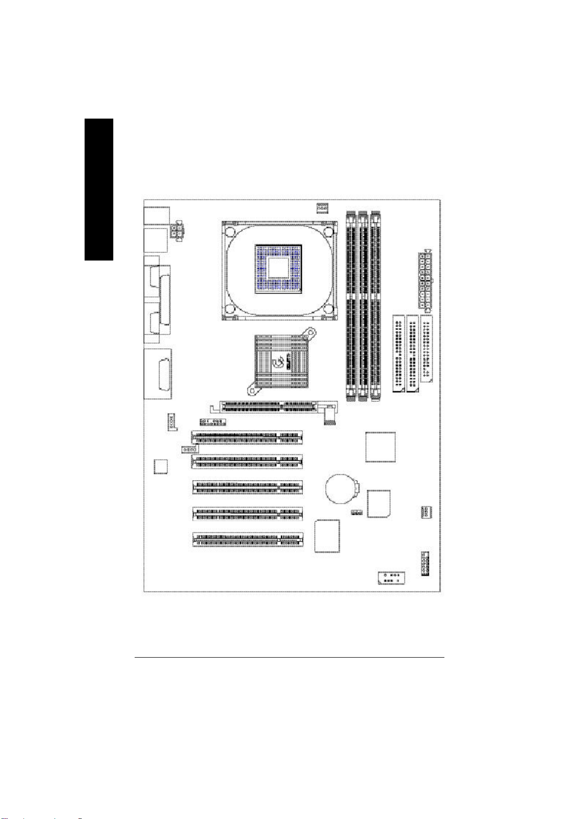
GA-8IRE Motherboard Layout
English
KB_MS
USB
COMA
COMB
LINE_OUTMIC_IN
LINE_IN
AC97
LPT1
GAME
CD_IN
AUX_12V
AUX_IN
P4 Titan-DDR
F_AUDIO
SOCKET478
GA-8IRE
CPU_FAN
PCI1
PCI2
PCI3
PCI4
PCI5
AGP
IT8702
BATTERY
DDR1
CLR_CMOS
DDR2
ICH2
BIOS
DDR3
IDE2
ATX
IDE1
SYS
FAN
F_PANEL
FLOPPY
FRONT USB
- 6 -GA-8IRE Motherboard
Page 14
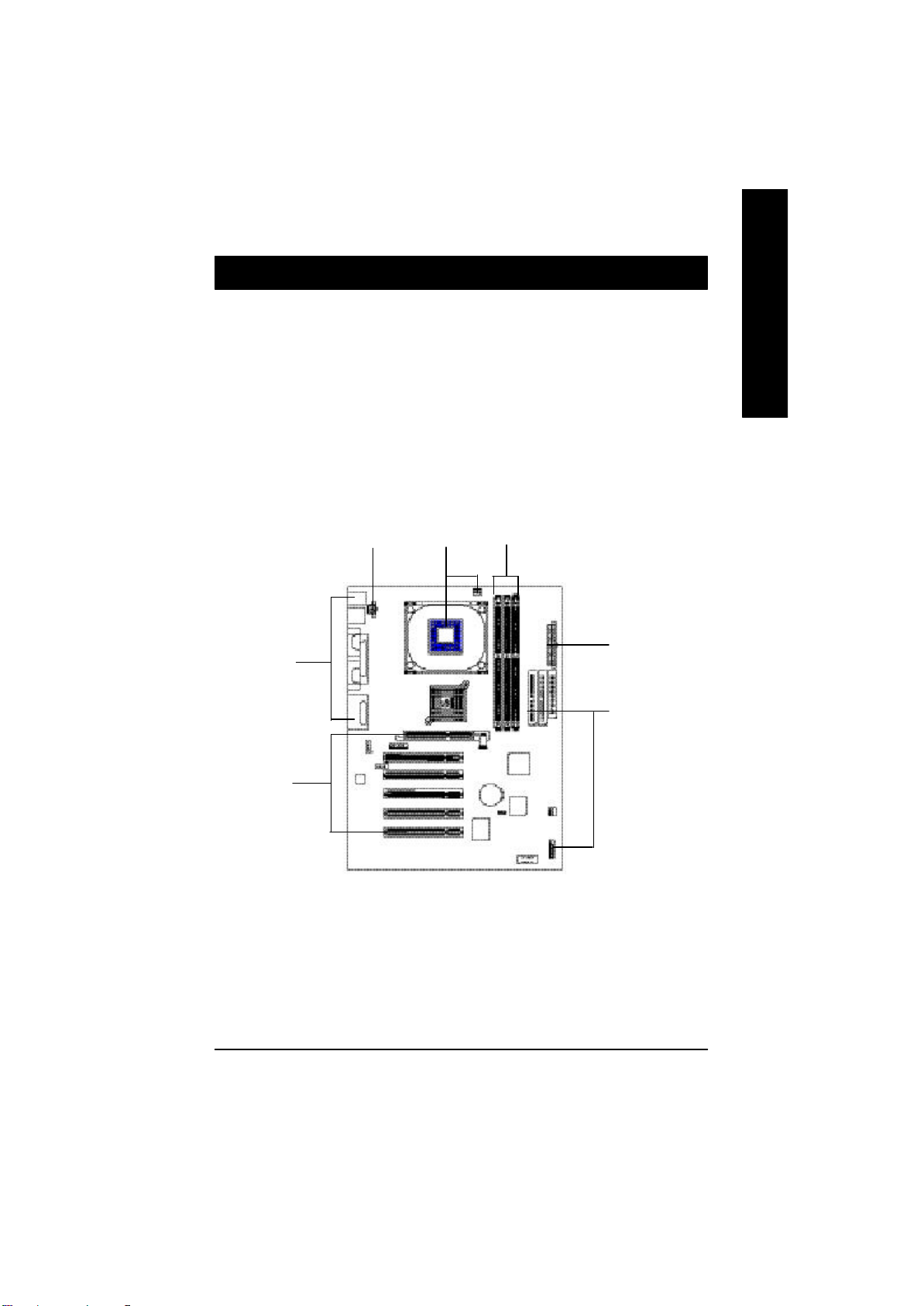
Chapter 2 Hardware Installation Process
To set up your computer, you must compl ete the following setps:
Step 1- Install the Central Processi ng Unit (CPU)
Step 2- Install memory modules
Step 3- Install expansion cards
Step 4- Connect ribbon cables, cabinet wires, and power supply
Step 5- Setup BIOS s oftware
Step 6- Install supporting software tools
English
Step 4
Step3
Step4
Step 2Step1
Step 4
Step 4
- 7 - Hardware Installation Process
Page 15

Step 1: Install the Central Processing Unit (CPU)
Step 1-1 CPU Installation
English
Pin1 indicator
CPU Top V iew CPU Bott om View
Socket Actuation Lever
1. Pull up the CP U socket lever
and up to 90-degree angle.
3. Press down the CPU socket
lever and finish CPU installation.
M
Please make sure the CPU type is supported by the motherboard.
Pin1indicator
Pin1 indicator
2. Locate Pin 1 in the socket and look
for a (golden) cut edge on the CPU
upper corner. Then insert the CPU
into the socket.
M
If you do not match the CPU socket Pin 1 and CPU cut edge well, it will cause
improper installation. Please change the insert orientation.
- 8 -GA-8IRE Motherboard
Page 16

Step 1-2 : CPU Heat Sink Installation
English
1. Hook one end of the cooler
bracket to the CPU socke t first.
M
Plea se use Intel approved cooling fan.
M
We recommend you t o apply the thermal tape to provide better heat conduction between
your CPU and heats ink.
(The CPU cooling fan might stick to the CPU due to the hardening of the thermal paste.
During this condition if you t ry to remove the cooling fan, you might pull the processor out
of t he CPU socket alone with the cooling fan, and might damage the processor. To avoid
this from happening, we suggest you to either use thermal tape instead of thermal paste, or
remove the cooling fan wit h extreme caution.)
M
Mak e sure the CPU fan power cable is plugged in to the CPU fan connector, this completes
the installa tion.
M
Ple ase refer to CPU heat sink user’s manual for more detail installation procedure.
2. Hook the oth er end of the
cooler bracket to the CPU
socket.
- 9 - Hardware Installation Process
Page 17

Step 2: Install memory modules
The moth erboard has 3 dual inline memory module (DIMM) sockets, but it can only support a maximum
of 4 banks of DDR memory. DDR slot 1 uses 2 banks, DDR slot 2&3 share the remaining 2 banks.
English
Plea se refer to the following tables for possible memory configurations supported. The BIOS will automatically detects memory type and size. To install the memory mo dule, just push it vertically into the DIMM
Slot .The DIMM module can only fit in one direction due to the notch. Memory size can vary between
sockets.
Total Memory Sizes With Unbuffered DDR DIMM
Devices used on DIMM 1 DIMM x 64 / x 72 2 DIMMs x 64 / x 72 3 DIMMs x 64 / x 72
64 Mbit (2M x8x4 banks) 128 MBytes 256 MBytes 256 MBytes
64 Mbit (1M x16x4 banks) 32 MBytes 64 MBytes 96 MBytes
128 Mbit(4M x8x4 banks) 256 MBytes 512 MBytes 512 MBytes
128 Mbit(2M x16x4 banks) 64 MBytes 128 MBytes 196 MBytes
256 Mbit(8M x8x4 banks) 512 MBytes 1 GBytes 1 GBytes
256 Mbit(4M x16x4 banks) 128 MBytes 256 MBytes 384 MBytes
512 Mbit(16Mx8x4 banks) 1 GBytes 2 GBytes 2 GBytes
512 Mbit(8M x16x4 banks) 256 MBytes 512 MBytes 768 MBytes
Notes: Double-sided x16 DDR memory devices are not support by Intel 845 chipset.
D:Double Sided DIMM S:Single Sided DIMM
X:Not Use
DDR1 DDR2 DDR3
S S S
D S S
D D X
D X D
S D X
S X D
DDR
1. The DIMM slot has a notch, so the
DIMMmemory module can only fit in one direction.
2. Insert the DIMM memory module verticallyinto the
DIMM slot. Then push it down.
3. Close the pla stic clip at both edges of theDIMM slots
to lock the DIMM module.
Reverse the installation steps when you wish to
remove the DIMM module.
M
When STR/DIMM LED is ON, do not install/remove DIMM from socket.
M
Please note that the DIMM module can only fit in one direction due to
the two notches. Wrong orientation will cause improper installation.
Please change the insert orientation.
- 10 -GA-8IRE Motherboard
Page 18

Step 3: Install expansion cards
1. Read the related expansion card’s instruction document before install the expansion card into
the co mputer.
2. Remove your computer’s chassis cover, screws and sl ot bracket from the computer.
3. Press the expansion card firmly into expansion slot in motherboard.
4. Be sure the metal contacts on the card are indeed seated in the slot.
5. Replace the screw to secure the slot bracket of th e expansion card.
6. Replace your computer’s chassi s cover.
7. Power on the computer , if necessary, setup BIOS utility of expansion card from BIOS.
8. Install rela ted driver from the operating system.
Please carefully pull out the small whitedrawable bar at the en d of the AGP slot when
AGP Card
you try to install/ Uninstall the AGP card.
Please align the AGP card to the onboard
AGP slot and press firmly down on the slot .
Make sure your AGP card is locked by the
small white- drawable bar.
English
- 11 - Hardware Installation Process
Page 19

Step 4: Connect ribbon cables, cabinet wires, and power
supply
English
Step 4-1 : I/O Back Panel Introduction
u
v
u
PS/2 Keyboard and PS/2 Mouse Connector
PS/2 Mouse Connector
(6 pin Female)
PS/2 Keyboard Connector
(6 pin Female)
w
v USB Con nector
USB 0
USB 1
x
y
ØThis conn ector supports standard PS/2
keyboard and PS/2 mouse.
ØBefore you connect your device(s) into USB
connector(s), please make sure your device(s)
such as USB keyboard, mouse, scanner, zip,
speaker..etc. Have a standard USB interface.
Also make sure your OS (Win 95 with USB
supplement, Win98, Windows 2000, Windows
ME, WinNT with SP 6) supports USB controller.
If your OS does not support USB controller,
please contact OS vendo r for possible patch or
driver upgrade. For more information please
contact your OS or device(s) vendors.
- 12 -GA-8IRE Motherboard
Page 20

w
Parallel Port and Serial Ports (COMA/COMB)
English
Parallel Port
(25 pin Female)
COMA COMB
Serial Ports (9 pin Male)
x
Game /MIDI Ports
Joystick/ MIDI (15 pin Female)
y Audio Connectors
ØThis connector supports 2 standard COM ports
and 1 Parallel port. Device like printer can be
connected to Parallel port ; mouse and modem
etc can b e connected to Serial ports.
ØThis connector supports joystick, MIDI keyboard
and other relate audio devices.
Line In
Ø After install onboard audio driver, you may connect
speaker to Line Out jack, micro phone to MIC In jack.
Device like CD-ROM , walkman etc can be connected
to Line-In jack.
MIC InLine Out
- 13 - Hardware Installation Process
Page 21

Step 4-2 :Connectors Introduction
English
A
L
K
J
I
H
M
A) CPU_FAN G) F_PANEL
B) ATX H) FRONT_USB
C) FLOPPY I) AUX_IN
D) IDE1/ID E2 J) CD_IN
E) BATTE RY K) F_AUDIO
F) SYS_FAN L) AUX_12V
M) CLR_CMOS
B
C
D
E
F
G
- 14 -GA-8IRE Motherboard
Page 22

L) AUX_12V( +12V Power Connector)
123
GND
GND
+12V
+12V
4
English
ØThis connector (ATX +12V) suppliesthe CPU
operation voltage (Vcore).
If this " ATX+ 12V connector" is no t connected,
system cannot boot.
A) CPU_FAN (CPU Fan Connector)
+12V/Control
GND
Sense
1
Ø Please note, a proper installation of the CPU
cooler is essential to prevent the CPU from
running under abnormal condition or
damaged by overheating.The CPU fan
connector supports Max. current up to 600mA .
F) SYS_FAN (System Fan C onnector)
GND
+12V/Control
1
NC
B) ATX (ATX Power Connector)
20
5V SB (Stand by +5V)
+12V
Power Good
GND
V CC
GND
V CC
GND
3.3V
3.3V
1
V CC
V CC
-5V
GND
GND
GND
PS- ON(Soft On/Off)
GND
-12V
3.3V
Ø AC power cord should only be connected to your power supply unit after ATX power cable and
other related d evices are firmly connected to the mainboard.
- 15 - Hardware Installation Process
Page 23

D ) IDE1 / IDE2 Connector (Primary/Secondary)
English
IDE2
Ø Importan t Notice:
Please co nnect first harddisk to IDE1
and connect CDROM to IDE2.
1
IDE1
C ) FLOPPY (Floppy Connector)
1
I ) AUX_IN ( AU X In Connector)
GND
AUX-L
AUX-R
1
E) BATTERY (BAT)
+
J) CD_IN (CD Audio Line In Connector)
CD-R
1
GND
CD-L
CAUTION
v Danger of explosion if battery is incorrectly
replaced.
v Replace only with the same or equivalent
type recommended b y the manufacturer.
v Dispose of used batteries according to the
man ufacturer’s instructions.
- 16 -GA-8IRE Motherboard
Page 24

H ) FRONT_USB (Fr ont USB Connector)
GND
NC
USB D3+
USB D3-
Power
1
NC
USB D2-
USB D2+
GND
Power
K ) F_AUDIO (F_AUDIO Connector)
Ø Be care ful with the polarity of the front
panel USB connector. Check the pin
assignment while yo u connect the front
panel USB cable. Please contact your
nearest dealer for optional fron t panel
USB cable.
English
Incase speaker (L)
GND
GND
GND
1
GND
+12V
MIC
GND
Incase speaker (R)
Rear Audio (R)
Rear Audio (L)
GND
Front Audio (R)
Front Audio (L)
Ø If you want to use Front Audio connector, you
must remove 1 1-12, 13-14 Jumper.
In order to utilize the front audio header, your
chassis must have fron t audio connector. Also
plea se make sure the pin assigment on the cable
is the same as the pi n assigment on the MB
header. To find ou t if the chassis you are buying
support front audio co nnector, please contact
your dealer
- 17 - Hardware Installation Process
Page 25

G ) F_P ANEL (2x7 pins jumper)
English
13
RSTRST+
SPK+
1
SPK-
HD-
HD (IDE Hard Disk Active LED) Pin 1: LED anode(+)
SPK (Speaker Connector) Pin 1: VCC(+)
RST (Reset Switch) Open: Normal Operation
PD+/PD_G-/PD_Y-(Power LED) Pin 1: LED anode(+)
PW (Soft Power Connector) Open: Normal Operation
PW+
PW-
PD+
PD_GPD_Y-
1
HD+
1
2 14
Pin 2: LED cathode(-)
Pin 2- P in 3: NC
Pin 4: Data(-)
Close: Reset Hardware System
Pin 2: LED cathode(-)
Pin 3: LED cathode(-)
Close: Power On/Off
Ø Please connect the power LED, PC speaker, reset switch and power switch etc of your chassis
front panel to the F_PANEL connector according to the pin assi gnment above.
M ) CLR_C MOS (Clear CMOS Function)
1 1
1-2 close: Clear CMOS
Ø Please note: You may clear the CMOS data to itsdefault values by this jumper.
2-3 close: Normal
"#" Default doesn’t include the “Shunter” to pr event from improper use this
jumper . To clear CMOS, temporarily short 1-2 pin.
- 18 -GA-8IRE Motherboard
Page 26

Chapter 3 BIOS Setup
BIOS Setup is an overview of the BIOS Setup Program. The program that allows users to modify the
basic system configuration. This type of informati on is stored in battery-backed CMOS RAM so that it
retains the Setup info rmation when the power is turned off.
EN TERING SETUP
After power on the computer, pressing <Del> immediately during POST (Power On Self Test) it will allow
you to enter standard BIOS CMOS SETUP.
If you require more advanced BIOS settings, please go to “Advanced BIOS” setting menu.To enter
Advanced BIOS setting menu, press “Ctrl+F1” key on the BIOS screen.
GETTIN G HELP
Main Menu
The on-line description of the highlighted setup function is displayed at the bottom of the screen.
Status Page Setup Menu / Option Page Setup Menu
Press F1 t o pop up a small help window that describes the appropriate keys to use and the possible
selections for the highlighted item. To exit the Help Window press <Esc>.
The Main Menu
Once you enter Award BIOS CMOS Setup Utility, the Main Menu will appear on the screen. The Main
Menu allows you to select from eight setup functions and two exit choices. Use arrow keys to select
among the items and press <Enter> to accept or enter the sub-menu.
English
CMOS Setup Utility-Copyright (C) 1984-2002 Award Software
}Standard CMOS Features Load Fail-Safe Defaults
}Advanced BIOS Features Load Optimized Defaults
}Integrated Peripherals Set Supervis or Password
}Power Management Setup Set User Password
}PnP/PCI Configurations Save & Exit Setup
}Frequency/Voltage Control Exit Without Saving
Top Performance
ESC:Quit higf: Select Item
F8: Q-Flash F10:Save & Exit Setup
Time, Date, Hard Disk Type...
Figure 1: Main Menu
- 19 - BIOS Setup
Page 27

l
l
English
l
l
l
l
l
l
l
l
l
l
l
Standard CMOS Features
This setup page includes all the items in standard comp atible BIOS.
Advanced BIOS Features
This setup pa ge includes all the items of Award special enhanced features.
Integrated Peripherals
This setup page includes all onboard peripherals.
Power Management Setup
This se tup page includes all the items of Green function features.
PnP/PCI Configurations
This setup page includes all the configurations of PCI & PnP ISA resources.
Freq uency/Voltage Control
This setup page is control CPU’s clock and frequency ratio.
Top Performance
If you wish to maximize the performance of your system, set "Top Performance" as "Enabled".
Load Fail-Safe Defaults
Fail-Safe Defau lts indicates the value of the system parameters which the system would
be in safe configuration.
Load Optimized Defaults
Optimized Defau lts indicates the value of the system parameters which the system would
be in best performance configuration.
Set Supervisor password
Change, set, or disable password. It allows you to limit access to the system and Setup,
or just to Setup.
Set User password
Change, set, or disable password. It allows you to limit access to the system.
Save & Exit Setup
Save CMOS value settings to CMOS and exit setup.
Exit Without Saving
Abandon all CMOS value changes and exit setup.
- 20 -GA-8IRE Motherboard
Page 28

Load Optimi zed Default
CMOS Setup Utility-Copyright (C) 1984-2002 Award Software
}Standard CMOS Features Load Fail-Safe Defaults
}Advanced BIOS Features Load Optimized Defaults
}Integrated Peripherals Set Supervis or Password
}Power Management Setup Set User Password
}PnP/PCI Configurations Save & Exit Setup
}Frequency/Voltage Control Exit Without Saving
Top Performance
F
Load Optimized Defaults
Load Optimized Defaults? (Y/N)?Y
ESC:Quit higf: Select Item
F8: Q-Flash F10:Save & Exit Setup
Load Optimized Defaults
Figure 10: Load Optimized Defaults
Selecting this field loads the factory defaults for BIOS and Chipset Features which the
system automatically detects.
To Load Optimized, move cursor , by pressing the arrow keys on the keyboard ,to highlight
the optimized d efault and press enter key then press "Y" if you decide to load this option.
Save & Exit Setup
CMOS Setup Utility-Copyright (C) 1984-2002 Award Software
}Standard CMOS Features Load Fail-Safe Defaults
}Advanced BIOS Features Load Optimized Defaults
}Integrated Peripherals Set Supervis or Password
}Power Management Setup Set User Password
}PnP/PCI Configurations Save & Exit Setup
}Frequency/Voltage Control Exit Without Saving
Top Performance
F To save exit the BIOS setting screen press F10, and press "Y" if you want to save setting. By
typing "N" or "ESC" will take you back to setup screen.
Save to CMOS and EXIT (Y/N) ?Y
ESC:Quit higf: Select Item
F8: Q-Flash F10:Save & Exit Setup
Save Data to CMOS
Figure 12: Save & Exit Setup
English
If you want to realize the BIOS setup information in detail, please download this manual from Gigabyte web http://www.gigabyte.com.tw.
- 21 - BIOS Setup
Page 29

Q-Flash Introduct ion
A. What is Q-Flash Utility?
English
mode, no more fooling around any OS.
B. How to use Q-Flash?
a. After power o n the computer, pressing <Del> immediately during POST (Power On Self Test) it
will allow you to enter AWARD BIOS CMOS SETUP, then press <F8> to enter Q-Flash utility.
Q-Flash utility is a pre-O.S. BIOS flash utili ty enables users to update its BIOS within BIOS
CMOS Setup Utility-Copyright (C) 1984-2002 Award Software
}Standard CMOS Features Load Fail-Safe Defaults
}Advanced BIOS Features Load Optimized Defaults
}Integrated Peripherals Set Supervis or Password
}Power Management Setup Set User Password
}PnP/PCI Configurations Save & Exit Setup
}Frequency/Voltage Control Exit Without Saving
Top Performance
ESC:Quit higf: Select Item
F8: Q-Flash F10:Save & Exit Setup
Enter Q-Flash Utility (Y/N)? Y
Time, Date, Hard Disk Type...
b. Q-Flash Utility
Q-Flash Utility V3.07
Flash Type/Size : SST 49LF002A / 256K
Keep DMI Data : Yes
Load BIOS from Floppy
Save BIOS to Floppy
Space Bar:Change Value
Enter: Run ESC: Reset h/i: Select Item
- 22 -GA-8IRE Motherboard
Page 30

Load B IOS From Floppy
!In the A:drive, i nsert the "BIOS" diskette, then Press Enter to Run.
1 File(s) found
XXXX.XX 256K
Total Size: 1.39M Free Size: 1.14M
F5: Refresh DEL: Delete ESC: Ret urn Main
Wher e XXXX.XX is name of the BIOS file.
!Press Enter to Run.
Are you sure to update BIOS?
[Enter] to contiune Or [ESC] ot abort...
!Press Enter to Run.
English
!! COPY BIOS Completed -Pass !!
Please press any key to continue
Congratulation! You have completed the flashed and now can restart system.
- 23 - BIOS Setup
Page 31

Revision History
Chapter 4 Driver Intallation
Picture below are shown in Windows ME (IUCD driver version 2.0)
English
Insert the driver CD-title that came with your motherboard into your CD-ROM driver, the driver
CD-ti tle will auto start and show the installation guide. If not, please double click the CD-ROM device icon
in "My computer", and execute the setup.exe.
A. Installing Intel 845 Chipset Driver
Please install this driver as the first priority.
this item installs the chipset driver utility
that enableds Plug-n-Plag INF support for
Intel chipset component.
B. Installing Sound Driver
Click this item to install sound driver.
A: Intel 845 Chipset Driver Installation
Follow the setup that showing on the scween to install the Utility.
1. Click “Intel Chip set Software Installation Utility”
Item.
B: Soun d Driver Installation
Press "Audio" icon.
1.Click "SigmaTel" item.
2.Click "SigmaTel AC97
Audio Driver" item.
- 24 -GA-8IRE Motherboard
Page 32

Chapter 5 BIOS Flash Procedure
BIOS update procedure:
Method 1:
If your OS is Win9X, we recommend that you used Gigabyte @BIOSTM Program to flash BIOS.
English
Press "Tools" icon.
1.Click "Gigabyte Utilities".
(1)
Click "P".
Methods and steps:
I. Update BIOS through Internet
a. Click "Internet Update" icon
b. Click "Update New BIOS" icon
c. Select @BIOSTM sever ("G igabyte @BIOSTM sever 1 in Taiwan" and "Gigabyte
@BIOSTM sever 2 in Taiwan" are available for now, the others will be completedsoon)
d. Select the exact model name on your motherboard
e. System will automatically download and update the BIOS.
Click here.
(3)
2.Click "@BIOS Writer Utility
v.1.08q".
(2)
- 25 - BIOS Flash Procedure
Page 33

II. Update BIOS NOT through Internet:
English
III. Save BIOS
IV. Check out supported motherboard and Flash ROM:
check out which kind of motherboard and which brand of Flash ROM are supported.
Note:
a. Do not click "Internet Update" icon
b. Click "Update New BI OS"
c. Please select "All Files" in dialog box while opening the old file.
d. Please search for BIOS unzip file, downloading from internet or a ny other methods (such
as: 8IRE.F1).
e. Complete upda te process following the instruction.
In the very beginning, there is "Save Current B IOS" icon shown in dialog box. It means to save
the current BIOS version.
In the very beginning, t here is "About this program" icon shown in dialog box. It can help you
a. In method I, if it sh ows two or more motherboard's model names to be selected, please
make sure your motherboard's model name again. Selecting wrong model name will
cause the system unbooted.
b. In method II, b e sure that motherboard's model name in BIOS unzip file are the same as
your motherboard's. Otherwise, your system won't boot.
c. In method I, if the BIOS file yo u need cannot be found in @BIOSTM server, pl ease go onto
Gigabyte's web site for downloading and updating it according to method II.
d. Please note that an y interruption during updating will cause system unbooted
- 26 -GA-8IRE Motherboard
Page 34

Method 2:
We use GA-7VTX motherboard and Flash841 BIOS flash u tility as example.
Please flash the BIOS according to the following procedures if you are now under the DOS mode.
Flash BIOS Procedure:
STEP 1:
(1) Please make sure your system has installed the extraction utility such as winzip or pkunzip.
Firstly you have to install the extraction utility such as winzip or pkunzip for unzi p the files. Both
of these utilities are available on many shareware download pages like
http://www.shareware.cnet.com
STEP 2: Make a DOS boot diskette. (See example: Windows 98 O.S.)
Beware: Windows ME/2000 are not allowed to make a DOS boot diskette.
(1) With an available floppy disk in the floppy drive. Please leave the diskette "UN-write protected"
type. Double click the "My Computer" icon from Desktop, then click "3.5 diskette (A)" and right
click to select "Format (M)"
English
- 27 - BIOS Flash Procedure
Page 35

(2) Select the "Quick (erase)" for Format Type, and pick both "Display summary when finished" and
system fi les to it.
English
(3) After the floppy has been formatte d completely, please press "Close".
"Copy system files", after that press "Start". That will form at the floppy and transfer the needed
Beware: This procedure will erase all the prior data on that floppy, so please proceed accordingly.
- 28 -GA-8IRE Motherboard
Page 36

STEP 3: Download BIOS and BIOS utility program.
(1) Please go to Gigabyte website http://www.gigabyte.com.tw/index.html, and click "Support".
(2) From Support zone, click the "Motherboards BIOS & Drivers".
English
- 29 - BIOS Flash Procedure
Page 37

(3) We use GA-7VTX motherboard as example. Please select GA-7VTX by Model or Chipset
English
(4) Select an appropriate BIOS version (For example: F4), and click to download the file. It will pop
optional m enu to obtain BIOS flash files.
up a file do wnload screen, then select the "Open this file from its current location" and press
"O K".
- 30 -GA-8IRE Motherboard
Page 38

(5) At this time the screen shows the following picture, please click "Extract" button to unzip the
fil es.
(6) Please extra ct the download files into the clean bootable floppy disk A mentioned in STEP 2,
and press "Extract".
English
- 31 - BIOS Flash Procedure
Page 39

STEP 4: Make sure the system will boot from the floppy disk.
(1) Insert the floppy disk (contains boo table program and unzip file) into the floppy drive A. Then,
restart the system. The system will boot from the floppy di sk. Please press <DEL> key to enter
English
BIOS setup main menu when system is boot up.
(2) Once you enter the BIOS setup utility, the main menu will appear on the screen. Use the arrows
American Re leas e:09 /16/ 99
Megatrends AM IBIO S (C ) 1 999 Amer ican Meg atre nd
7VTX F1
Check System Health OK
AMD-Athlon(tm)Processor-900MHz
Checking NVRAM...
262144KB
Wait...
Press F1 to enter Dual BIOS Utility. Press ESC to quit
Press any key to contiune
( C ) American Megatrends Inc.,
63-0001-001199-00101111-071595-VIA_K7-GA7VTX1-F
to highlight the item "BIOS FEATURES SETUP".
AMIBIOS SIMPLE SETUP UTILITY - VERSION 1.24b
(C) 1999 American Megatrends, Inc. All Rights Reserved
STANDARD CMOS SETUP INTEGRATED PERIPHERALS
BIOS FEATURES SETUP HARDWARE MONITOR & MISC SETUP
CHIPSET FEATURES SETUP SUPERVISOR PASSWORD
POWER MANAGEMENT SETUP USER PASSWORD
PNP / PCI CONFIGURATION IDE HDD AUTO DETECTION
LOAD BIOS DEFAULTS SAVE & EXIT SETUP
LOAD SETUP DEFAULTS EXIT WITHOUT SAVING
ESC: Quit hifg : Select Item (Shift)F2 : Change Color F5: Old Values
F6: Load BIOS Defaults F7: Load Setup Defaults F10:Save & Exit
Time, Date , Hard Disk Type…
- 32 -GA-8IRE Motherboard
Page 40

(3) Press "Enter" to enter "BIOS FEATURES SETUP" menu. Use the arrows to highlight the item
"1st Boot Device", and then use the "Page Up" or "Page Down" keys to select "Floppy".
AMIBIOS SETUP - BIOS FEATURES SETUP
( C ) 2001 American Megatrends, Inc. All Rights Reserved
1st Boot Device : Floppy
2nd Boot Device : IDE-0
3rd Boot Device : CDROM
S.M.A.R.T. for Hard Disks : Disabled
BootUp Num-Lock : On ESC: Quit hifg: Select Item
Floppy Drive Seek : Disabled F1 : Help PU/PD/+/- : Modify
Password Check : Setup F5 : Old Values (Shift)F2: Color
F6 : Load BIOS Defaults
F7 : Load Setup Defaults
(4) Press "ESC" to go back to previous screen. Use the arrows to highlight the item "SAVE & EXIT
SETUP" then press "Enter". System will ask "SAVE to CMOS and EXIT (Y/N)?" Press "Y" and
"Enter" keys to confirm. Now the system will reboot automatically, the new BIOS setting will be
taken effect next boot-up.
AMIBIOS SIMPLE SETUP UTILITY - VERSION 1.24b
(C) 2001 American Megatrends, Inc. All Rights Reserved
STANDARD CMOS SETUP INTEGRATED PERIPHERALS
BIOS FEATURES SETUP HARDWARE MONITOR & MISC SETUP
CHIPSET FEATURES SETUP SUPERVISOR PASSWORD
POWER MANAGEMENT SETUP USER PASSWORD
PNP / PCI CONFIGURATION IDE HDD AUTO DETECTION
LOAD BIOS DEFAULTS SAVE & EXIT SETUP
LOAD SETUP DEFAULTS EXIT WITHOUT SAVING
ESC: Quit hifg : Select Item (Shift)F2 : Change Color F5: Old Values
F6: Load BIOS Defaults F7: Load Setup Defaults F10:Save & Exit
Save to CMOS and EXIT (Y/N)? Y
English
Save Data to CMOS & Exit SETUP
- 33 - BIOS Flash Procedure
Page 41

STEP 5: BIOS flashing.
(1) After the system boot fr om floppy disk, type "A:\> dir/w" and press "Enter" to check the entire
files in floppy A. Then type the "BIOS flash utility" and "BIOS file" afte r A:\>. In this case you
English
have to type "A:\> Flash841 7VTX.F4" and then press "Enter".
(2) Now screen appears the following Flash Utility main menu. Press "Enter", the highlighted item
will locate on the model name of the right-upper screen. Right after that, press "Enter" to start
BIOS Flash Utility.
Starting Windows 98…
Microsoft(R) Windows98
© Copyright Microsoft Corp 1981-1999
A:\> dir/w
Volume in drive A has no label
Volume Serial Number is 16EB-353D
Directory of A:\
COMMAND.COM 7VTX.F4 FLASH841.EXE
3 file(s) 838,954 bytes
0 dir(s) 324,608 bytes free
A:\> Flash 841 7VTX.F4
- 34 -GA-8IRE Motherboard
Page 42

(3) It will pop up a screen and asks "Are you sure to flash the BIOS?" Press [Enter] to continue the
procedure, or press [ESC] to quit.
Beware: Please do not turn off the system while you are upgrading BIOS. It will render your
BIOS corrupted and system totally inoperative.
Are you sure to flash the BIOS?
[Enter] to continue Or [Esc] to cancel?
(4) The BIOS flash completed. Please press [ESC] to exit Flash Utility.
English
EXIT?
[Enter] to continue Or [Esc] to cancel?
- 35 - BIOS Flash Procedure
Page 43

STEP 6: Load BIOS defaults.
Normally the system redetects all devices after BIOS has been upgraded. Therefore, we highly
recommend reloading the BIOS defaults after BIOS has been upgraded. This important step resets
English
everything after the flash.
(1) Take out the floppy diskette from floppy drive, and then restart the system. The boot up screen `
will indicate your motherboard model and current BIOS version.
(2) Don't forget to press <DEL> key to enter BIOS setup again when system is boot up. Use the
arrows to highlight the item "LOAD SETUP DEFAUL TS" then press "Enter". System will ask
American Re leas e:09 /16/ 99
Megatrends AM IBIO S (C ) 1 999 Amer ican Meg atre nd
7VTX F4
Check System Health OK
AMD-Athlon(tm)Processor-900MHz
Checking NVRAM...
262144KB
Wait...
Press F1 to enter Dual BIOS Utility. Press ESC to quit
Press any key to contiune
( C ) American Megatrends Inc.,
63-0001-001199-00101111-071595-VIA_K7-GA7VTX1-F
"Load Setup Defaults (Y/N)?" Press "Y" and "Enter" keys to confirm.
AMIBIOS SIMPLE SETUP UTILITY - VERSION 1.24b
(C) 2001 American Megatrends, Inc. All Rights Reserved
STANDARD CMOS SETUP INTEGRATED PERIPHERALS
BIOS FEATURES SETUP HARDWARE MONITOR & MISC SETUP
CHIPSET FEATURES SETUP SUPERVISOR PASSWORD
POWER MANAGEMENT SETUP USER PASSWORD
PNP / PCI CONFIGURATION IDE HDD AUTO DETECTION
LOAD BIOS DEFAULTS SAVE & EXIT SETUP
LOAD SETUP DEFAULTS EXIT WITHOUT SAVING
ESC: Quit hifg : Select Item (Shift)F2 : Change Color F5: Old Values
F6: Load BIOS Defaults F7: Load Setup Defaults F10:Save & Exit
Load Setup Defaults? (Y/N)?N
Load Setup Defaults
- 36 -GA-8IRE Motherboard
Page 44

(3) Use the arrows to highlight the item "SAVE & EXIT SETUP" and press "Enter". System will ask
"SAVE to CMOS and EXIT (Y/N)?" Press "Y" and "Enter" keys to confir m. Now the system will
reboot a utomatically, the new BIOS setting will be taken effect next boot-up.
AMIBIOS SIMPLE SETUP UTILITY - VERSION 1.24b
(C) 2001 American Megatrends, Inc. All Rights Reserved
STANDARD CMOS SETUP INTEGRATED PERIPHERALS
BIOS FEATURES SETUP HARDWARE MONITOR & MISC SETUP
CHIPSET FEATURES SETUP SUPERVISOR PASSWORD
POWER MANAGEMENT SETUP USER PASSWORD
PNP / PCI CONFIGURATION IDE HDD AUTO DETECTION
LOAD BIOS DEFAULTS SAVE & EXIT SETUP
LOAD SETUP DEFAULTS EXIT WITHOUT SAVING
ESC: Quit hifg : Select Item (Shift)F2 : Change Color F5: Old Values
F6: Load BIOS Defaults F7: Load Setup Defaults F10:Save & Exit
Save to CMOS and EXIT (Y/N)? Y
Save Data to CMOS & Exit SETUP
(4) Congratulate you have accomplished the BIOS flash procedure.
English
- 37 - BIOS Flash Procedure
 Loading...