

Page 1
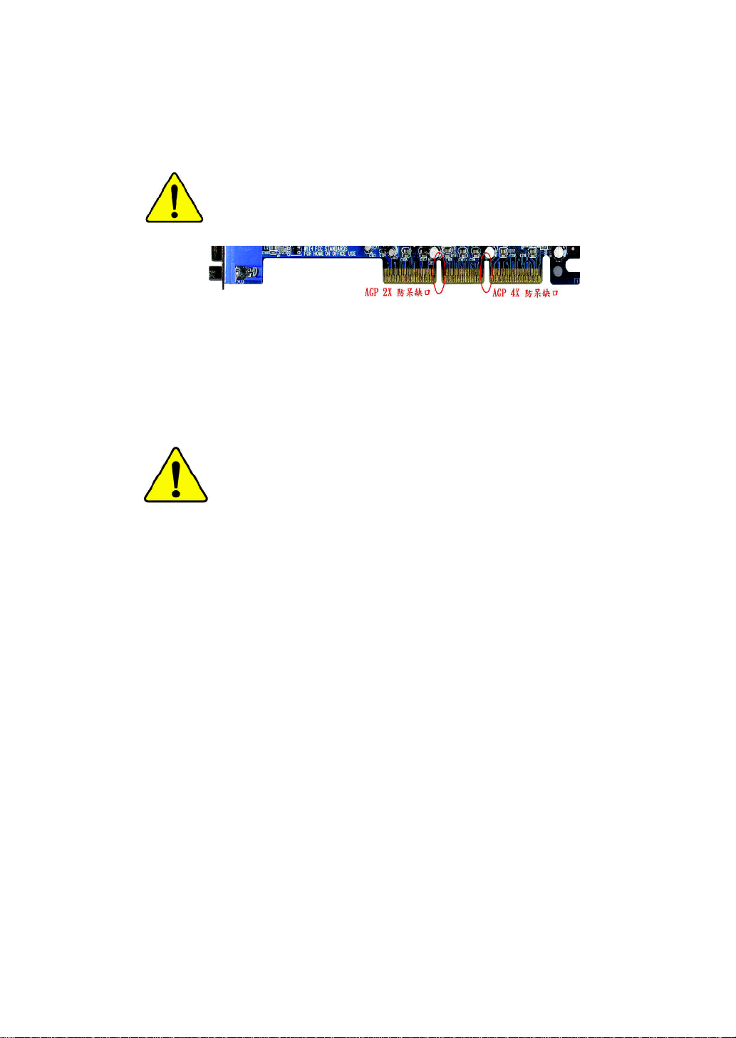
當您安裝AGP 卡時,請注意下述注意事項。
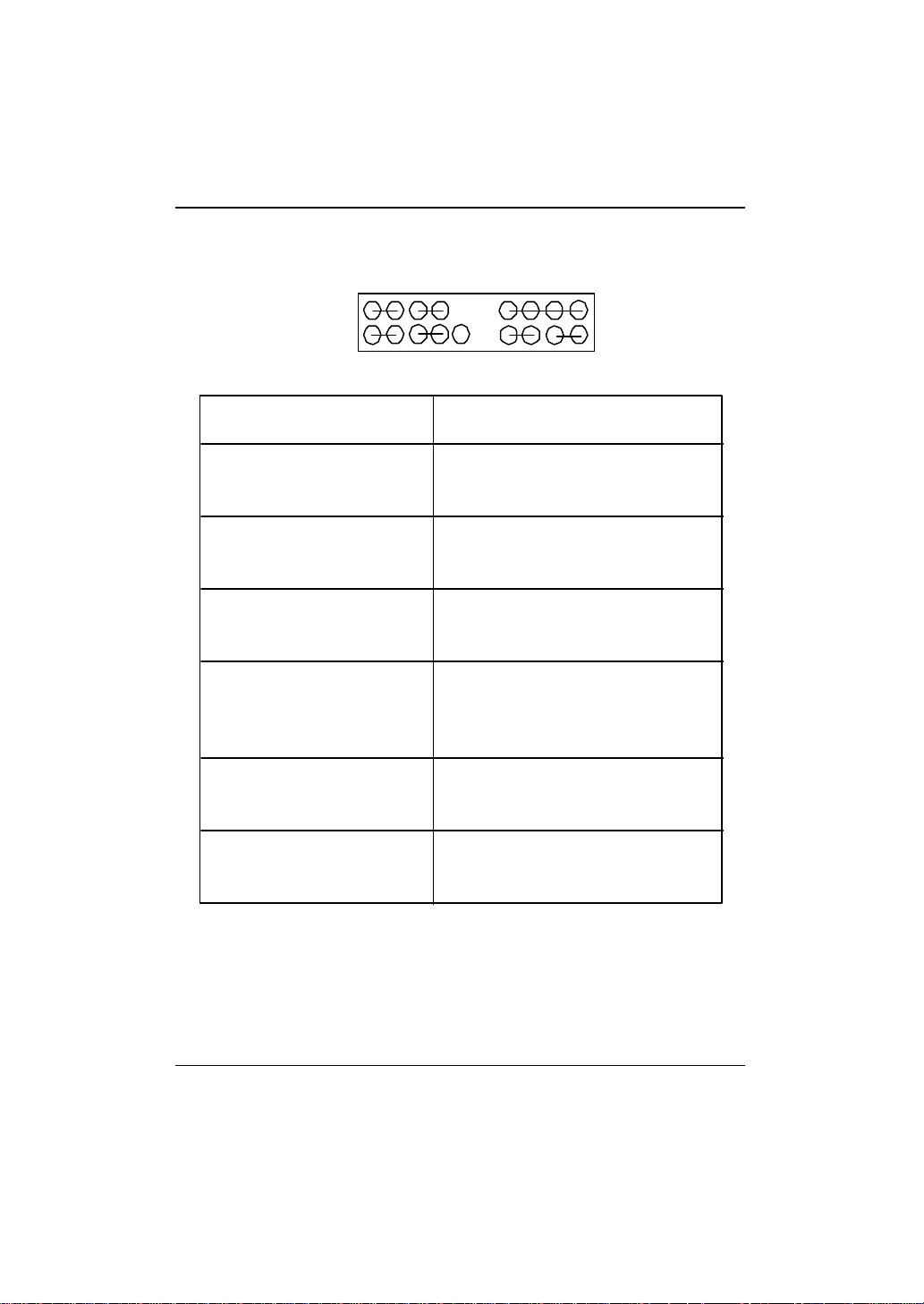
您的顯示卡若有AGP 4X 防呆缺口(如下圖),請再次確認
此卡的規格為AGP 4X(1.5V)。
不要使用AGP 2X (3.3V)卡,因為 Intel® 845(E/G)/850 (E)晶
片組不支援AGP 2X(3.3V),若您使用AGP 2X (3.3V) 卡時,
此主機板上的零件將會被燒毀。
範例一:Diamond Vipper V770 這塊顯示卡的金手指部份設
計成2X/4X插槽皆可使用,透過Jumper可切換於2X或4X,
出廠預設值為2X(3.3V),若您使用此卡在GA-8IR533 系
列主機板上,而且沒有將Jumper 切換至4X (1.5V)的模
式時,開機後會燒毀主機板上的零件。
範例二:某些SiS 305及Power Color所生產的某些ATi Rage
128 Pro 等顯示卡的金手指部份設計成2X/4X 插槽皆可使
用,但只支援2X(3.3V),若您使用此卡在GA-8IR533 系
列主機板上,開機後會燒毀主機板上的零件。
注意:技嘉科技所生產的AG32S(G)顯示卡,雖然採用ATi
Rage 128 Pro晶片,但此卡設計符合AGP4X的規格,因此
不會發生如範例二中燒毀零件的情況,請您安心使用。
Page 2
本手冊所有提及之商標與名稱皆屬該公司所有。
在科技迅速的發展下,此發行手冊中的一些規格可能會
有過時不適用的敘述,敬請見諒。
在此不擔保本手冊無任何疏忽或錯誤亦不排除會再更新
發行。手冊若有任何內容修改,恕不另行通知。
主機板上的任何貼紙請勿自行撕毀,否則會影響到產品
保固期限的認定標準。
Page 3

Ausschla ger Weg 41, 1F, 20537 Hamburg, Germany
( description of the apparatus, system, installation to which it refers)
(reference to the specification under which con formity is declared)
in accordance with 89/336 EEC-EMC Directive
o EN 55011 Limits and methods of measurement
o EN 55013
o EN 55014 Limits and methods of measurement
o EN 55015 Limits and methods of measurement
o EN 55020
T EN 55022 Limits and methods of measurement
o DIN VDE 0855
o part 10
o part 12
T CE marking
o EN 60065
o EN 60335
of radio disturbance characteristics of
industrial,scientific and medical (ISM
high frequency equipment
Limits and methods of measurement
of radio disturbance characteristics of
broadcast receivers and associated
equipment
of radio disturbance characteristics of
household electrical appliances,
portable tools and similar electrical
apparatus
of radio disturbance characteristics of
fluorescent lamps and luminaries
Immunity from radio interference of
broadcast receivers and associated
equipment
of radio disturbance characteristics of
information technology equipment
Cabled distribution systems; Equipment
for receiving and/or distribution from
sound and television signals
The manufacturer also declares the conformity of above mentioned product
with the actual required safety standards in accordance with LVD 73/23 EEC
Safety requirements for mains operated
electronic and related apparatus for
household and similar general use
Safety of household and similar
electrical appliances
(Stamp)
Declaration of Conformity
We, Manufacturer/Importer
(full address)
G.B.T. Technology Träding GMbH
declare that the product
Mother Board
GA-8IR 533
is in conformity with
o EN 61000-3-2*
T EN 60555-2
o EN 61000-3-3* Disturbances in supply systems cause
T EN 60555-3
T EN 50081-1
T EN 50082-1
o EN 55081-2
o EN 55082-2
o ENV 55104
o EN50091-2
(EC conformity marking)
o EN 60950
o EN 50091-1
Manufacturer/Importer
Date : M ay. 17, 2002
Disturbances in supply systems cause
by household appliances and similar
electrical equipment “Harmonics”
by household appliances and similar
electrical equipment “Voltage fluctuations”
Generic emission standard Part 1:
Residual commercial and light industry
Generic immunity standard Part 1:
Residual commercial and light industry
Generic emission standard Part 2:
Industrial environment
Generic emission standard Part 2:
Industrial environment
lmmunity requirements for household
appliances tools and similar apparatus
EMC requirements for uninterruptible
power systems (UPS)
Signature:
Name:
Timmy Huang
Timmy Huang
Page 4
DECLARATION OF CONFORMITY
Per FCC Part 2 Section 2.1077(a)
Responsible Party Name:
Add ress:
Phone/Fax No:
hereby declares that the product
Produ ct Name:
Model Nu mber:
Conforms to the following specifications:
FCC Part 15, Subpart B, Section 15.107(a) and Section 15.109
(a),Class B Digital D evice
Supplementary Information:
This device complies with part 15 of the FCC Rules. Operation is
subject to the following two conditions: (1) This device may not
cause harmful and (2) this device must accept any inference received,
including that may cause undes ired operation.
Representative Person’s Name:
Signature:
G.B.T. INC. (U .S.A.)
17358 Railroad Street
City of Indu stry, CA 91748
(818) 854-9338/ (818) 854-9339
Motherboard
GA-8I R533
ERIC LU
Eric Lu
Date:
May. 17,2002
Page 5

GA-8IR533 系列
P4 泰坦DDR 主機板
中文安裝使用手冊
®
Pentium
4 處理器主機板
Rev. 1004
12MC-8IR533-1004
Page 6

GA-8IR533 系列主機板
目錄
清點附件.................................................................................. 4
警告標語.................................................................................. 4
第一章 序言............................................................................ 5
特色彙總................................................................................................................ 5
GA-8IR533 系列主機板Layout 圖.................................................................. 7
第二章 硬體安裝步驟........................................................ 8
步驟1:安裝中央處理器(CPU) ..................................................................... 9
中央處理器之安裝 ............................................................................................. 9
中央處理器之散熱裝置安裝 ........................................................................... 10
步驟2: 安裝記憶體模組.............................................................................. 11
步驟3:安裝介面卡 .........................................................................................13
步驟4:連接所有訊號線、排線、電源供應線及面板控制線 14
步驟4-1:後方I/O 裝置鐵片介紹 .................................................................... 14
步驟4-2:插座及跳線介紹 .............................................................................. 16
步驟4-3:跳線介紹 .......................................................................................... 22
第三章BIOS 組態設定 ......................................................23
主畫面功能(BIOS 範例版本:F1) ........................................................... 24
標準CMOS 設定............................................................................................... 26
進階 BIOS 功能設定 .......................................................................................29
整合週邊設定................................................................................................... 31
2
Page 7

序言
省電功能設定................................................................................................... 36
隨插即用與PCI 組態設定 ..........................................................................39
電腦健康狀態................................................................................................... 40
頻率/ 電壓控制................................................................................................ 41
最高效能..............................................................................................................43
載入 Fail-Safe 預設值......................................................................................44
載入Optimized 預設值 .................................................................................... 45
設定管理者 (Supervisor)/ 使用者(User)密碼 .........................................46
離開SETUP 並儲存設定結果................................................................... 47
離開SETUP 但不儲存設定結果.............................................................. 48
第四章 技術文件參考資料............................................49
晶片組功能方塊圖 ........................................................................................49
Q-Flash 功能介紹 .............................................................................................. 50
Easy Tune
@ BIOS
TM
4 介紹............................................................................................. 52
TM
介紹..................................................................................................... 53
第五章 附錄..........................................................................54
3
Page 8
GA-8IR533 系列主機板
清點附件
þ GA-8IR533 系列主機板一片
þ 硬碟插座排線 x 1 / 軟碟插座排線 x 1
þ 主機板驅動程式光碟片 (IU C D)
þ GA-8IR533 系列中文安裝手冊
þ 電腦組裝秘笈
þ 2 埠通用串列埠插座排線 x 1
警告標語
主機板由許多精密的積體電路及其他元件所構成,這些積體電路很容易因為遭到靜
電影響而損失。所以請在正式安裝前,做好下列準備。
1. 請將電腦的電源關閉,最好拔除電源插頭。
2. 拿取主機板時請儘量避免觸碰金屬接線部份。
3. 拿取積體電路元件(CPU 、RAM )時,最好能夠戴上有防靜電手環。
4. 在積體電路未安裝前,需將元件置放在靜電墊或防靜電袋內。
5. 當您將主機板中的ATX電源供應器插座上的插頭拔除時,請確認電源供應
器的開關是關閉狀況。
安裝主機板至機殼中…
大多數電腦機殼的底部會有多個固定孔孔位,可使主機板確實固定並且不會短
路。請小心不要讓螺絲接觸到任何PCB板上的線路或零件,當印刷電路主機板表
面線路接近固定孔時,您可使用塑膠墊片來讓螺絲與主機板表面隔離過,避免造成
主機板損壞或故障。
4
Page 9

第一章 序言
特色彙總
規格 — 主機板採四層設計 ATX 規格19.6 公分x 29 .5公分
主機板 — GA-8IR5 33 系列主機板包括
GA-8IR 及GA-8IR533
中央處理器 — Socket 478 支援最新Intel M icro FC -PGA2 Pentium® 4 處理器
— 支援Intel
®
— Intel® Pentium® 4 400M Hz FSB
— 自動偵測 Pentium® 4 處理器並提供最佳化設定
— 2nd 快取記憶體取決於C PU
晶片組 — Chipset Intel
— ICH 2 I/O C ontroller Hub
記憶體 — 3 184-pin DDR DIM M 插槽
— 支援PC 1600 /PC2100 DD R DIM M
— 支援2.5V DD R DIM M
— 支援64bit EC C type DR AM integrity mode
— 最高容量可擴充至2GB
I/O 控制器 — ITE8 702
擴充槽 — 1 AGP 擴充槽支援4X (1.5V)裝置
— 5 PCI 擴充槽支援33M Hz 及PCI2.2 c ompliant
內建IDE — 2 IDE bus master (U DM A 33/ATA 66/ATA 100) IDE 埠可連接
4 ATAPI 裝置
— 支援PIO m ode 3,4 (UDMA33/ATA66/ATA100 IDE)及ATAPI CD-
ROM
內建周邊設備 — 1 個軟碟插座支援兩台磁碟機(360K, 720K, 1.2M, 1.44M
及2.88M bytes)
— 1 組並列埠插座可支援N ormal/E PP/EC P 模式
— 2 組串列埠插座(COM A & CO M B)
— 4 組U SB 埠插座(後端通用串列埠 x 2,前端通用串列埠 x 2)
— 1 組前端音源插座
®
Pentium
4 (Northwood, 0.13 m) 處理器
®
845D HOST/AGP/Controller
序言
續下頁.......
5
Page 10

GA-8IR533 系列主機板
內建音效晶片 — RealTek ALC650 C ODEC
— Line Out : 2 個前置喇叭
— Line In : 2 個後置喇叭(由軟體切換)
— Mic I n : 中置 / 重低音(由軟體切換)
— SPDIF out : 由軟體切換
— CD In / AUX In / Game Port
PS/2 插座 — PS/2 鍵盤插座及PS/2 滑鼠插座
BIOS — 使用經授權AWARD BIOS, 2M bit快閃記憶體
— 支援Q-Fl ash
附加特色 — PS/2 鍵盤開機
— PS/2 滑鼠開機
— 支援STR 功能(Suspend-To-RAM)
— AC Rec ov ery
— USB 鍵盤/滑鼠 w ake up from S3
— 支援@BIOS
— 支援Easy Tune 4
™
™
請依據您CPU的規格來設定CPU 的頻率,我們不建議您將系統速度設定超
過硬體之標準範圍,因為這些規格對於周邊設備而言並不算是符合標準規
格。如果您要將系統速度設定超出標準規格,請評估您的硬體規格設定,
例如:CPU ,顯示卡,記憶體,硬碟來設定。
6
Page 11
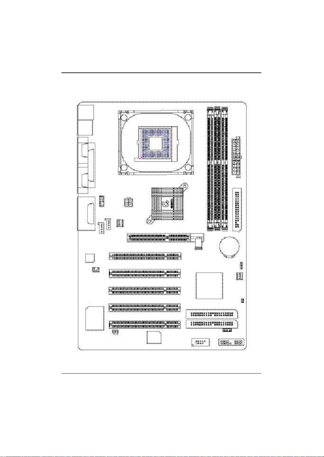
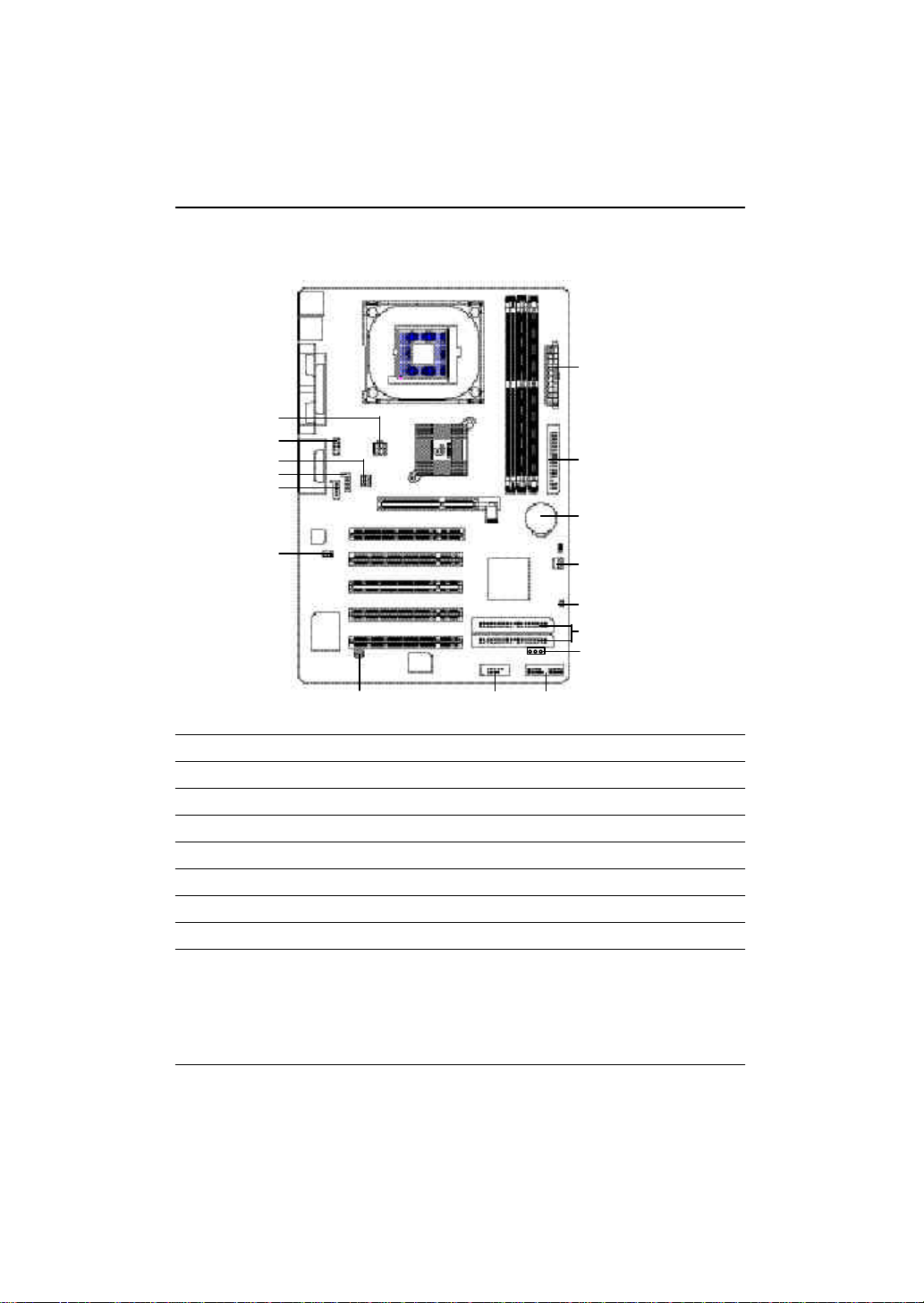
GA-8IR533 系列主機板Layout 圖
KB_MS
硬體安裝步驟
USB
LINE_OUTMIC_IN
COMA
COMB
LINE_IN
CODEC
SUR_CEN
LPTGAME
F_AUDIO
AUX_IN
ATX_12V
CPU_FAN
CD_IN
P4 Titan533
SOCKET478
845D
PCI1
PCI2
PCI3
PCI4
AGP
GA-8IR533
DDR1
ICH2
DDR2
DDR3
BATTERY
CLR_CMOS
ATX
FDD
SYS _FAN
CI
ITE8702
SPDIF
BIOS
PCI5
F_USB1
PWR_LED
IDE2
IDE1
F_PANEL
7
Page 12
GA-8IR533 系列主機板
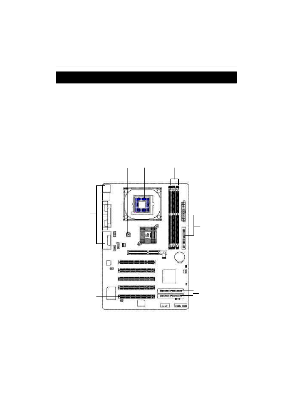
第二章 硬體安裝步驟
請依據下列方式,完成電腦的安裝:
步驟 1 - 安裝中央處理器 (CPU)
步驟 2 - 安裝記憶體模組
步驟 3 - 安裝所有介面卡
步驟 4 - 連接所有訊號線、排線、電源供應線及面板控制線
步驟 5 - 完成 BIOS 組態設定
步驟 6 - 安裝軟體驅動程式
步驟 4
步驟 1
步驟 3
步驟 1
步驟 2步驟 4
步驟 4
步驟 4
8
Page 13
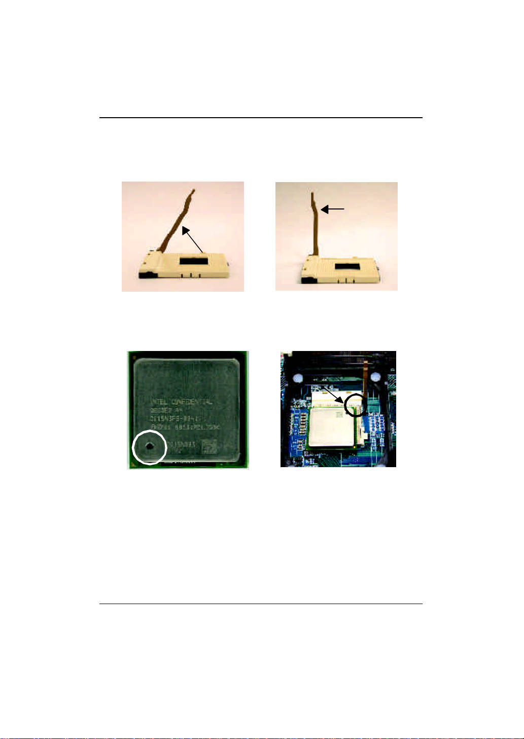
步驟1:安裝中央處理器(CPU)
中央處理器之安裝
硬體安裝步驟
連桿拉至
約 65 度角
1. 將處理器插座連桿向上拉起至約
65度,連桿有時會有卡住的感覺, 此
時稍加用力繼續將連桿拉至90 度,
並會有”喀”的聲音。
第 1 腳
3. 中央處理器正面
連桿
2. 將處理器插座連桿向上拉起
至90 度角的位置。
第 1 腳
4. 將處理器的第一腳( 金色三腳記號
處) 對準插座上的缺腳記號再將處
理器插入插座。處理器插入定位
後,再將連桿向下按至原位。
M 請確認您使用的中央處理器為本主機板的支援範圍。
M 請注意 CPU的第一腳位置,若您插入的方向錯誤,處理器就無法插
入,請立刻更改插入方向。
9
Page 14

GA-8IR533 系列主機板
中央處理器之散熱裝置安裝
1. 先將C PU 散熱風扇一邊的卡
榫以平均施力的方式往下
壓,直至扣緊為止;以同樣
地方式再將另一邊卡榫扣
緊。
2. 將 C PU 散熱風扇的電源線插
入主機板上的”C PU 散熱風
扇電源插座”。
M 使用經 I nte l 認證過的散熱風扇。
M CPU 與風扇之間建議黏上散熱膠帶以增強散熱效果。
(當塗抹在CPU上的散熱膏呈現硬化的現象時,可能會產生散熱
風扇黏住 CPU 的情況,在此情況下如果您想移除散熱風扇將會
有損毀 CPU 的可能。為避免此情況發生,我們建議您可使用散
熱膠帶來取代散熱膏,或是小心地移除散熱風扇。)
M 依您實際所使用的散熱風扇,以正確方向將風扇確實扣緊。
M 確認 CP U 散熱風扇電源線接至 CPU FAN 接頭,完成安裝。
(詳細安裝步驟請參考散熱風扇的使用手冊。)
10
Page 15
硬體安裝步驟
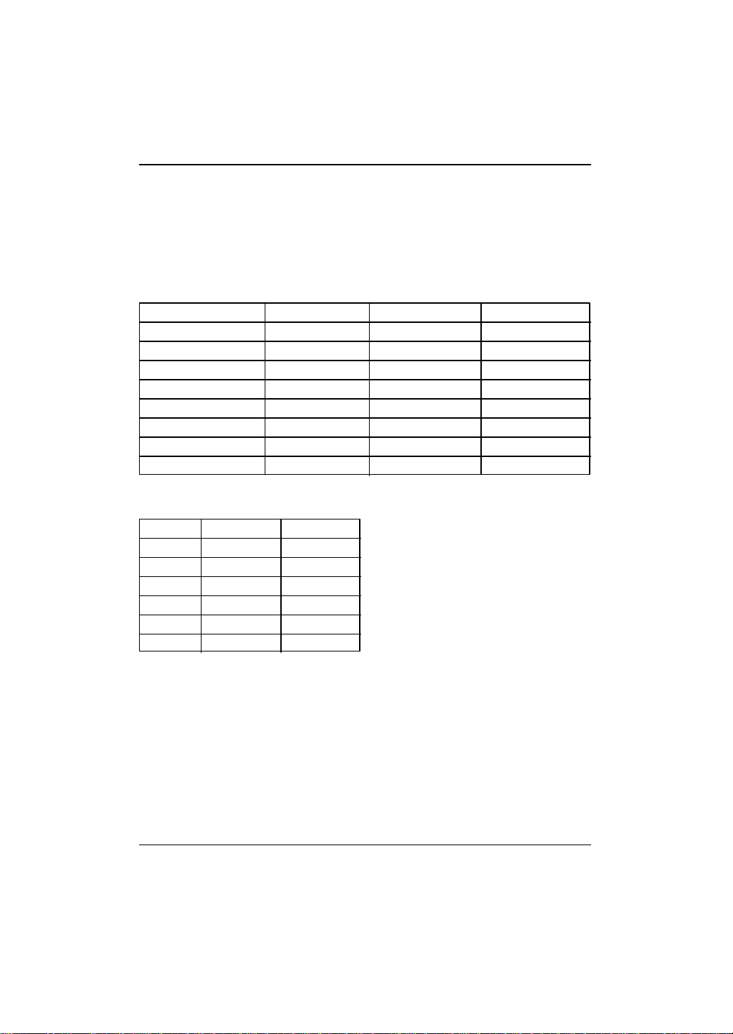
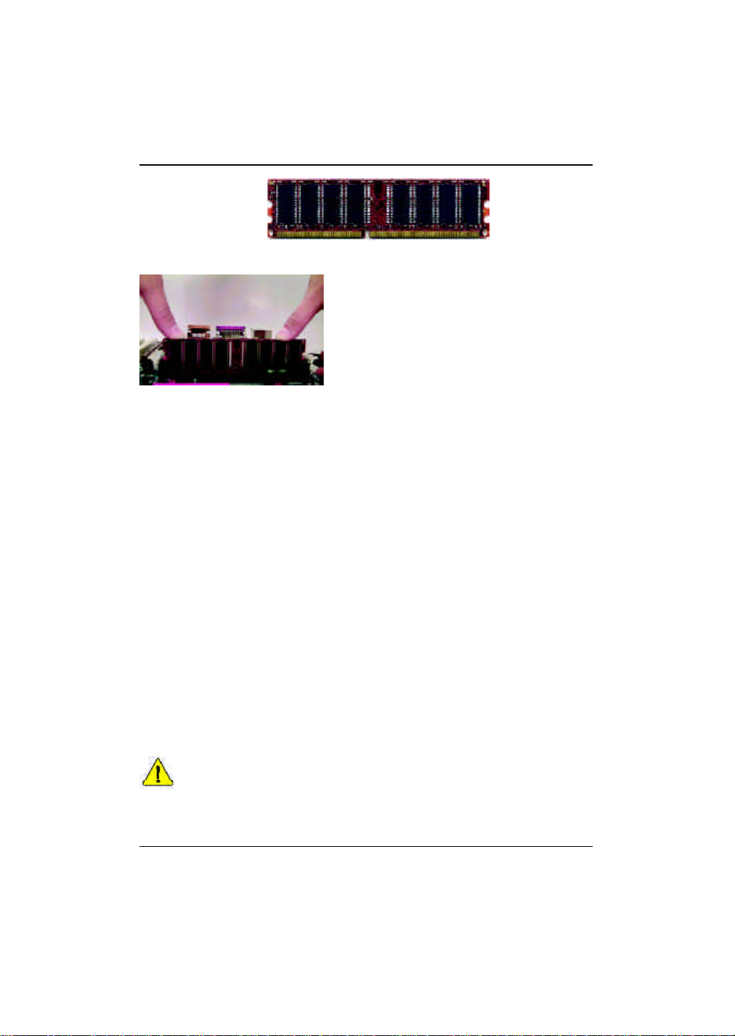
步驟2: 安裝記憶體模組
本主機板有3條184Pin(DIMM)擴充槽,BIOS會自動偵測記憶體的規格及其大小。安
裝記憶體只需將DIMM插入其插槽內即可,在不同的插槽,記憶體大小可以不同,
建議使用相同顆粒的記憶體模組,如:NEC, Toshiba, PQI, Winbond 。
使用 Unbuffered DDR DIMM 時的總記憶容量
Devices used on DIMM 1 DIMM x 64 / x 72 2 DIMMs x 64 / x 72 3 DIMMs x 64 / x 72
64 Mbit (2Mx8x4 banks) 128 MBytes 256 MBytes 768 MBytes
64 Mbit (1Mx16x4 banks) 32 MBytes 64 MBytes 96 MBytes
128 Mbit(4Mx8x4 banks) 256 MBytes 512 MBytes 768 MBytes
128 Mbit(2Mx16x4 banks) 64 MBytes 128 MBytes 192 MBytes
256 Mbit(8Mx8x4 banks) 512 MBytes 1 GBytes 1.5 GBytes
256 Mbit(4Mx16x4 banks) 128 MBytes 256 MBytes 384 MBytes
512 Mbit(16Mx8x4 banks) 1 GBytes 2 GBytes 3 GBytes
512 Mbit(8Mx16x4 banks) 256 MBytes 512 MBytes 768 MBytes
備註:Intel 8 45E/G 晶片組不支援雙顆粒 x 1 6 DDR 記憶體模組。
DDR1 DDR2 DDR3
S S S
D S S
D D X
D X D
S D X
S X D
D: Double Sided DIMM S: Single Sided DIMM
X: Not Use
11
Page 16
GA-8IR533 系列主機板
DDR
1. 記憶體模組有一個凹痕,所以只能以一個方向
插入。
2. 扳開記憶體模組插槽卡榫,以平均施力的方
式,將記憶體模組下壓推入插座。記憶體模
組插入定位後,將卡榫向內按至卡住。
3.將卡楯向內推,確實卡住記憶體模組DIMM 。
一旦固定位置,兩旁的卡楯便自動卡住記憶
體模組予以固定。試著輕輕搖動記憶體模
組,若不搖晃則裝置成功。
DDR 功能介紹
DDR(Double Data Rate)是PC 產業在 SDR AM 架構上的一項重要演進,利用雙倍的
記憶體頻寬可解決系統資料的瓶頸問題。建立在 SD RA M 的基礎架構設計之上,
DDR 是一項高效能及低成本兼具的創新技術,能使記憶體廠商、OEM 系統廠商在
熟悉的標準上建構新一代的電腦系統產品。
因為具有優良可行性、價格以及整體市場的支援性,DDR SDRAM 將提供優良的
解決方式以及將現有的SDRAM 轉換到DDR SDR AM 的最佳路徑。
DDR 可雙倍讀與寫的資料傳輸速率,利用最高可達2.1GB/s 的傳輸速度,DDR 能
使系統廠商建立一個高效能及低滯留時間的DRAM架構,適合在伺服器、工作站、
高階PC 以及進階整合性電腦系統使用。相對於目前SDR AM 的 3. 3 v olts 高核心電
壓,DDR 的2.5 v olts 超低核心電壓將使得DDR 為小型規格的桌上電腦以及筆記型
電腦的最佳技術解決方案。
M 記憶體模組設計有防呆標示,若您插入的方向錯誤,記憶體模組
就無法插入,請立刻更改插入方向。
M 當 ST R/D IMM 燈指示燈在亮的狀態時,請勿插拔DIMM 。
12
Page 17
硬體安裝步驟
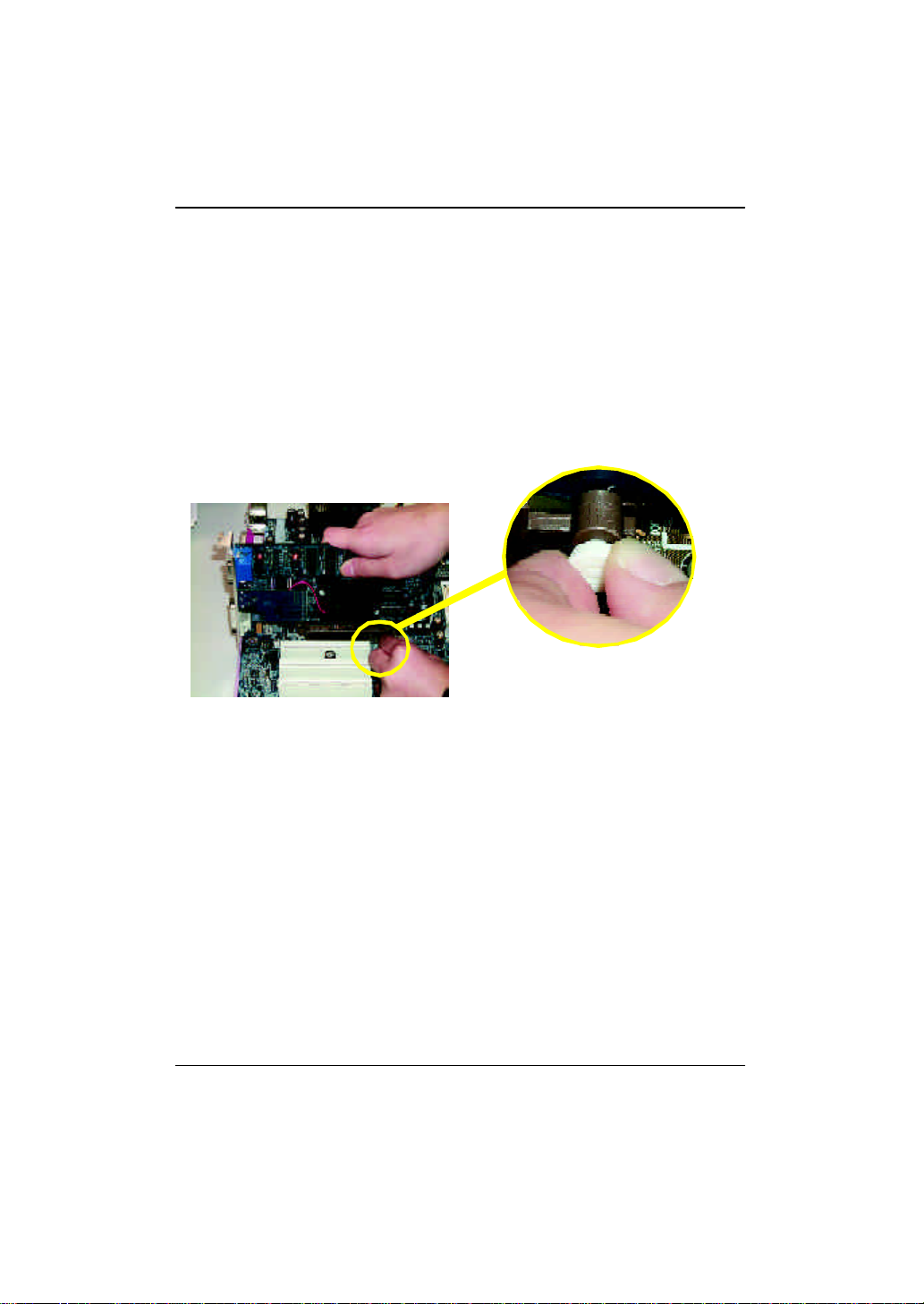
步驟3:安裝介面卡
1. 在安裝介面卡之前請先詳細閱讀介面卡之使用手冊並將您電腦的電源關掉。
2. 將您電腦外殼拆除,並且讓自己保持接地。(為了使人體不帶電,以防止靜電傷
害電腦設備)。
3. 鬆開螺絲,移開介面卡安裝擴充槽旁的金屬擋片。
4. 將介面卡小心且確實的插入在擴充槽中。
5. 請確定所有介面卡皆確實固定插在該擴充槽,並將螺絲鎖回。
6. 重新將電腦機殼蓋上。
7. 接上電源線,若有必要請至BIOS 程式中設定介面卡之相關設定。
8. 安裝相關驅動程式。
當您要安裝/ 移除AGP 卡時,請將白
AGP 卡
色拉桿向外拉,再將AGP 卡緩緩插
入AGP 擴充槽中,放開拉桿確實卡
住AGP 卡。
13
Page 18
GA-8IR533 系列主機板
步驟4:連接所有訊號線、排線、電源供應線及面
板控制線
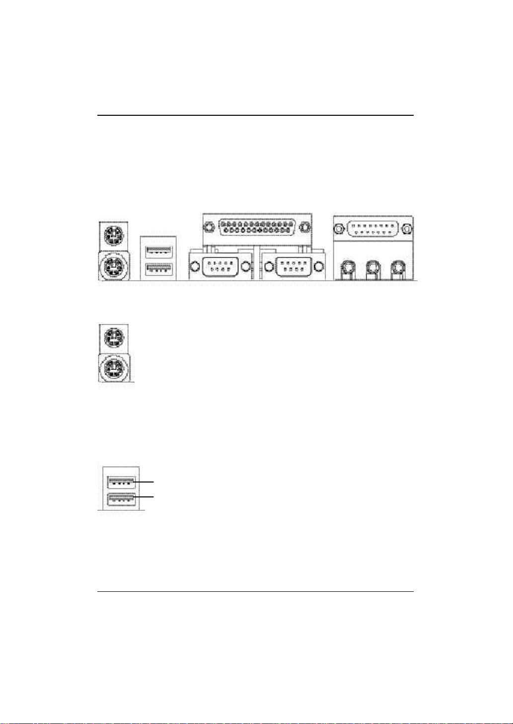
步驟4-1:後方I/O 裝置鐵片介紹
u
v
u PS /2 鍵盤及 PS /2 滑鼠插座
PS/2 滑鼠插座
(6 pin Female)
PS/2 鍵盤插座
(6 pin Female)
v 通用序列埠
USB 0
USB 1
w
Ø 本主機板提供標準P S/ 2 鍵盤介面及
PS/2 滑鼠介面插座。
Ø 當你要使用通用串列埠連接埠時,必
須先確認您要使用的週邊裝置為標準
的USB 介面,如:USB鍵盤,滑鼠,
USB掃瞄器,U SB ZIP ,U SB 喇叭
等…。而且您也必須確認您的作業系
統是否有支援此功能,或是需要另外
再掛其他的驅動程式,如此才能正常
工作,詳情請參考USB週邊裝置的使
用手冊。
x
y
14
Page 19
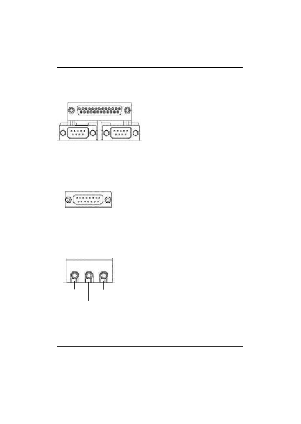
w 串列埠 A/ 串列埠 B/ 印表機並列埠插座
硬體安裝步驟
並列埠插座
(25 pin Female)
串列埠A
串列埠 (9 pin Male)
x 遊戲搖桿控制埠
遊戲搖桿控制埠
(15 pin Female)
y 音源插座
Ø 本主機板支援兩組標準的串列埠傳輸協
定之週邊裝置,及一組標準的並列傳輸
協定之週邊裝置, 您可以依據您的需求
連接您需要的裝置,如並列埠有印表
機,串列埠有滑鼠、數據機等。
串列埠B
Ø 本主機板支援標準的音效輸入接腳及遊
戲搖桿控制埠,您在設定完成內建音效
的驅動程式後,即可將喇叭輸出接腳接
在音源輸出端。
Line Out
Ø 麥克風接腳可接在麥克風輸入端,至
於音源輸入端可以接上如:光碟機,
隨身聽及其他音源輸入接腳。
MIC In
Line In
15
Page 20
GA-8IR533 系列主機板
步驟4-2:插座及跳線介紹
P
O
N
M
L
A
B
C
K
J
HI
A) ATX I) F_USB1
B) FDD J) S PDI F
C) BATTERY K) SUR_CEN
D) SYS_FAN L) AUX_I N
E) CI M) CD_I N
F) IDE1/IDE2 N) CPU_FAN
G) PWR_LED O) F_AUDIO
H) F_PANEL P) ATX_12V
D
E
F
G
16
Page 21
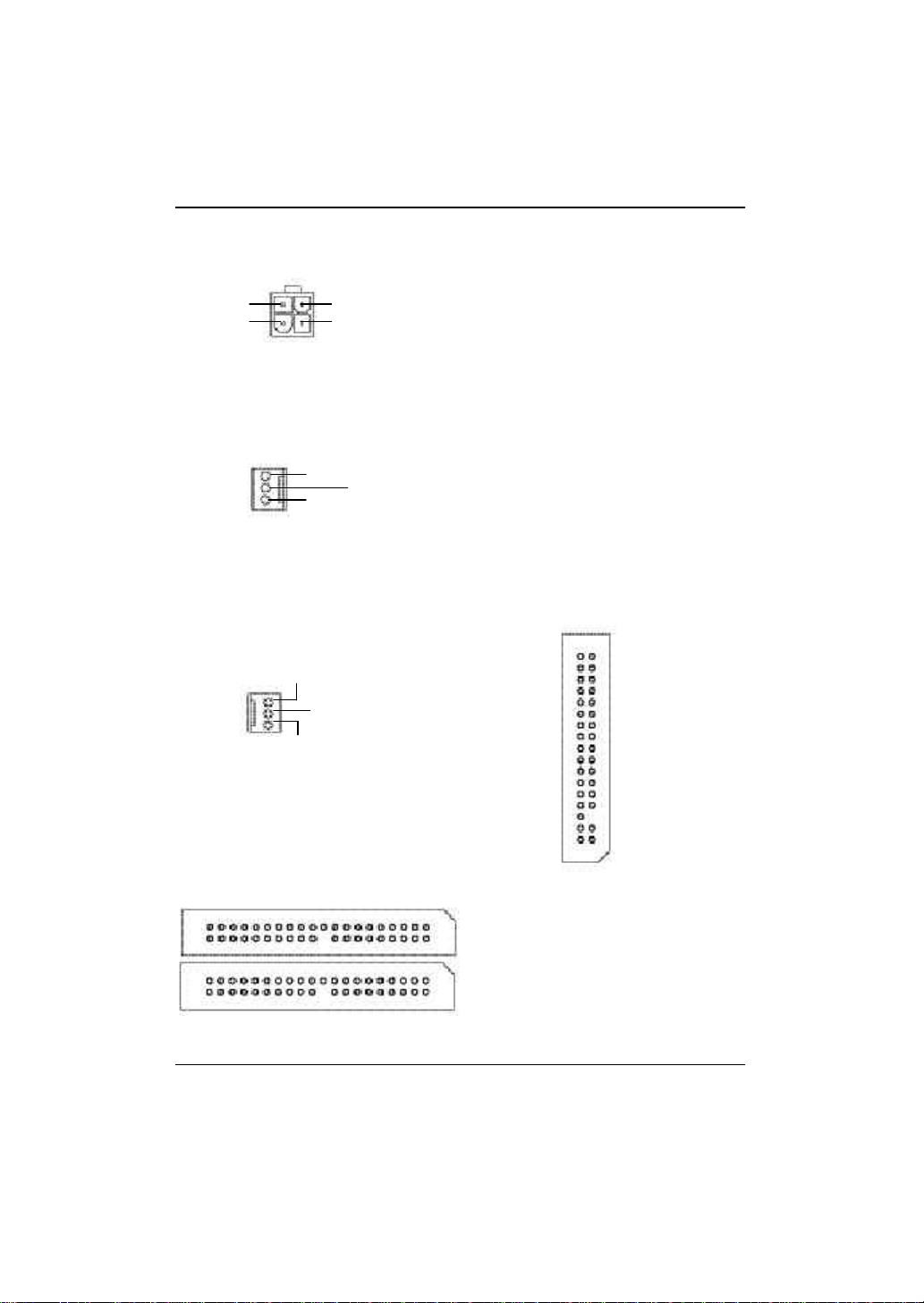
P) ATX12V ( +12V 電源插座)
硬體安裝步驟
+12V
43
+12V
接地線接地線
2
1
Ø 請特別注意,此ATX + 12V 電源插座為
N ) CPU_FAN (CPU 散熱風扇電源插座)
Ø 請特別注意,當我們安裝處理器時要
訊號腳
+12V/Control
接地腳
1
D) SYS_FAN
B ) FDD (軟碟機插座)
(系統散熱風扇電源插座)
接地腳
1
+12V/Control
無作用
提供CPU 電源使用。若沒有插上
ATX+ 12V 電源插座,系統將不會啟動。
特別注意將散熱風扇安裝妥當,不然
您的處理器將處於不正常的工作環
境,甚至會因為溫度過高,而燒毀處
理器。此CPU散熱風扇電源插座,提
供最大電流為600 毫安培。
F) IDE1/ IDE2 (第一組及第二組 IDE插座)
第二組IDE 插座
第一組IDE 插座
1
Ø 請特別注意:
17
1
FDD
請將您的第一顆硬碟連接第一組 IDE
插座,光碟機接至第二組 IDE 插座。
Page 22
GA-8IR533 系列主機板
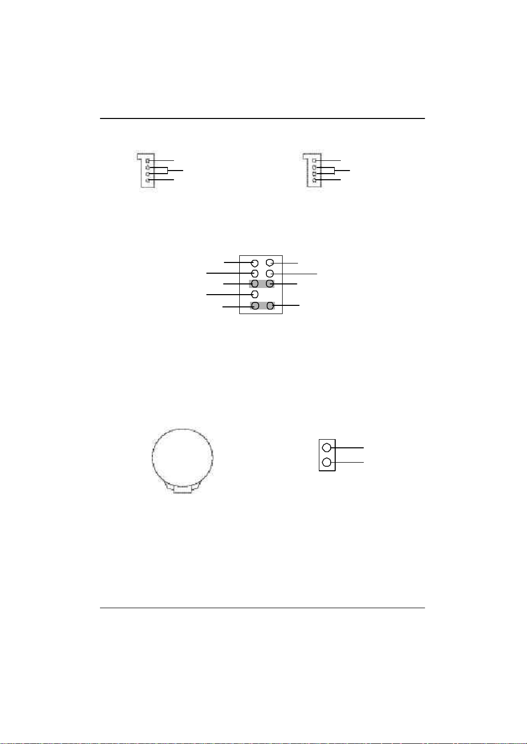
M) CD_IN (光碟機音源插座) L) AUX_IN (外接音源輔助插座)
左聲道音源輸入
接地腳
右聲道音源輸入
11
左聲道音源輸入
接地腳
右聲道音源輸入
O) F_AUDIO (第二組音源插座)
1
2
MIC
REF
Front Audio (R)
Reserved
Front Audio (L)
9 10
Ø 請特別注意,當您購買電腦機殼時,可以選購音效接腳是設計在電腦機殼的
前面面板上,此時就可以使用第二組音源接腳,如果有任何問題可就近向經
銷商詢問相關問題。注意:若您要使用第二組音源接腳,請移除Pin5-6,Pin9-10
的Jumper 。
C) BATTERY (電池)
E) CI (電腦機殼被開啟偵測)
+
接地腳
電源
Rear Audio (R)
Rear Audio (L)
接地腳
1 訊號腳
警 告
v 如果電池有任何不正確的移除動作,
將會產生危險。
v 如果需要更換電池時請更換相同廠
牌、型號的電池。
v 有關電池規格及注意事項請參考電池
廠商之介紹。
Ø 本主機板提供電腦機殼被開啟偵測功
能,當您要使用此功能需搭配外接式
偵測裝置。
18
Page 23
硬體安裝步驟
A ) ATX (ATX Power)
20
+12V
5V SB (Stand by +5V)
Power Good
接地線
VCC
接地線
VCC
接地線
3.3V
3.3V
1
Ø 請特別注意,先將AC 交流電(110/220V)拔除,再將ATX電源插頭緊密的插入主機
板的ATX電源插座,並接好其相關配備才可以將AC交流電(110/220V)插入交流電
源插座。
VCC
VCC
-5V
接地線
GND
接地線
PS-ON(Soft On/Off)
接地線
-12V
3.3V
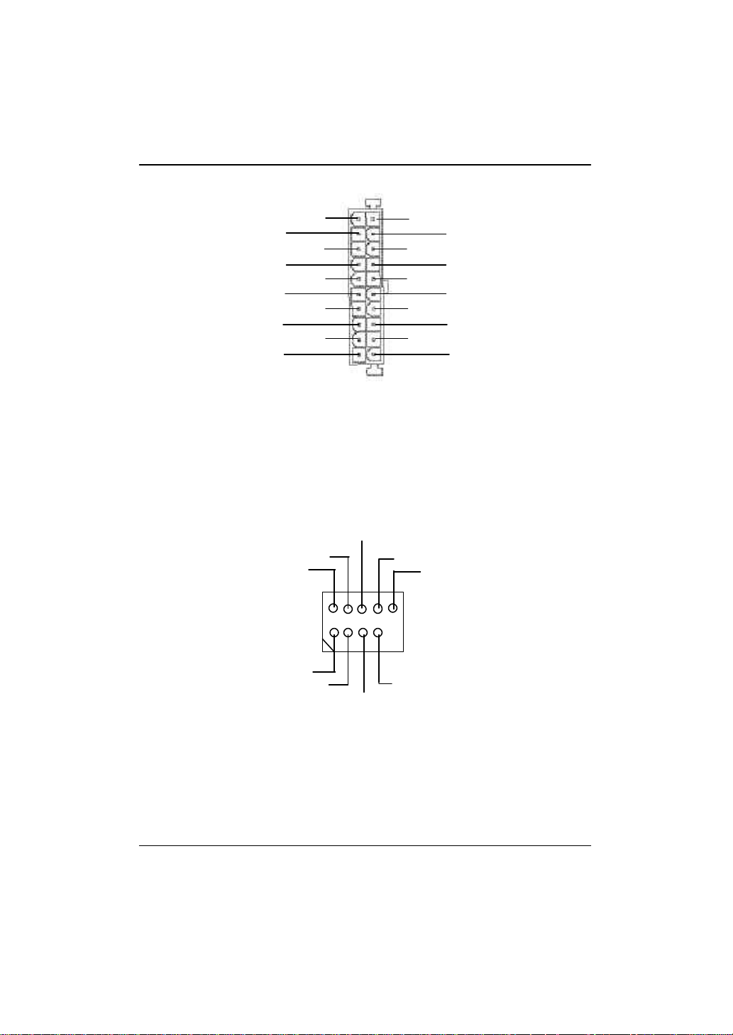
I) F_USB1 (前端通用串列埠插座)(F_USB1 黃色插座為 USB 1.1 )
USB Dy+
USB Dy-
電源
接地線
USB Over Current
1
電源
USB Dx-
USB Dx+
Ø 請特別注意,前端 U S B 接腳是有方向性的,所以安裝U S B 裝置時,要特別
注意極性,而且前端USB 連接排線為選擇性的功能套件,可以聯絡相關代
理商購買。
接地線
19
Page 24
GA-8IR533 系列主機板
H) F_PANEL (前端控制面板跳線)
MPD+
1
MPD-
PW+
1
PW-
SPK+
1
SPK-
2 20
1 19
1
HD+
HD-
RST-
1
RST+
NC
1
GD+
GD-
1
GN+
GN-
GN (Green Switch)省電模式開關 Open: Normal Operation 一般運作
Close: Entering Green Mode 進入省電模式
GD (Green LED)省電模式指示燈 Pin 1: LED anode(+)省電指示燈正極
Pin 2: LED cathode(-)省電指示燈負極
M 請注意正負極性
HD (IDE Hard Disk Active LED) Pin 1: LED anode(+)硬碟指示燈正極
硬碟動作指示燈 Pin 2: LED cathode(-)硬碟指示燈負極
M 請注意正負極性
SPK (Speaker Connector)喇叭接腳 Pin 1: VCC(+) +5v 電源接腳
Pin 2- Pin 3: NC 空腳
Pin 4: Data(-) 訊號接腳
RST (Reset Sw itch)系統重置開關 Open: Normal Operation 一般運作
Close: Reset Hardware System
強迫系統重置開機
M 無正負極性正反皆可使用
PW (Soft Pow er Connector) Open: Normal Operation 開路:一般運作
按鍵開關機 Close: Power On/Off 短路:開機/ 關機
M 無正負極性正反皆可使用
MPD (Message LED/Power/ Pin 1: LED anode(+)省電指示燈正極
Sleep LED) Pin 2: LED cathode(-)省電指示燈負極
M 請注意正負極性
Ø 請特別注意,當您購買電腦機殼時,電腦機殼的控制面板有電源指示燈,喇
叭,系統重置開關,電源開關等,你可以依據上列表格的定義加上連接。
20
Page 25

硬體安裝步驟
K ) SUR_CEN
G ) PW R_LED
SUR OUTR
2
1
接地腳
SUR OUTL
1
BASS_OUT
CENTER_OUT
MPD+
MPD-
MPD-
J ) S PDIF
1
接地腳
數位音效輸出腳
Ø So ny / Ph ilip Digital Interface Format為新
力/ 飛利浦所制定的數位介面格式,
SPDIF 輸出能夠提供數位音效給外接
的喇叭或者第三代音效編碼格式 (AC-3)
解壓縮成杜比數位格式。請特別注
意,使用此功能時,須確認您的音響
系統具有數位輸入(SPDIF In)功能。
SPDIF 輸出是提供數位音效輸出供給
AC3 杜比解碼,最高可支援5.1聲道之
輸出。
VCC
21
Page 26

GA-8IR533 系列主機板
步驟4-3:跳線介紹
1) CLR_CMOS #
1
1) CLR_CMOS (清除 CMOS 資料功能接腳)
1-2 短路: 清除CMOS 內的資料 2-3 短路: 一般運作
1
Ø 請特別注意,你可以透過這個Jump er將您主機板內CMOS 的資料清除乾淨回到
最原始的設定。
1
"#" 為避免不當使用此功能,此跳線不附跳帽。如果您要使用
Clear CMOS 功能,請將 1-2 Pin 短路。
22
Page 27

BIOS 組態設定
第三章 BIOS 組態設定
基本上主機板所附Award BIOS 便包含了CMOS SETUP 程式,以供使用者自行依照
需求,設定不同的數據,使電腦正常工作,或執行特定的功能。
CMOS SETUP會將各項數據儲存於主機板上內建的 CMOS SRAM中,當電源關閉時,
則由主機板上的鋰電池繼續供應CMOS SRAM 所需電力。
當電源開啟之後,BIOS 開始進行POST(Power On Self Test開機自我測試)時,按
下<Del >鍵便可進入Aw ard BIOS 的CM OS S ETU P 主畫面中。如果您需要進階的
BIOS 設定,當您在BIOS 設定畫面時按下“Ctrl+F1”即可進入。
操作按鍵說明
h 移到上一個項目
i 移到下一個項目
f 移到左邊的項目
g 移到右邊的項目
Esc 回到主畫面,或從主畫面中結束SETUP 程式
Page Up 改變設定狀態,或增加欄位中之數值內容
Page Down 改變設定狀態,或減少欄位中之數值內容
F1 可顯示目前設定項目的相關說明
F2 功能保留
F3 功能保留
F4 功能保留
F5 可載入該畫面原先所有項目設定(但不適用主畫面)
F6 可載入該畫面之Fail-Safe 預設設定(但不適用主畫面)
F7 可載入該畫面之Optimized 預設設定(但不適用主畫面)
F8 Q-Flash 功能
F9 功能保留
F10 儲存設定並離開CMOS SETUP 程式
23
Page 28

GA-8IR533 系列主機板
如何使用輔助說明
主畫面的輔助說明
當您在SETUP 主畫面時,隨著選項的移動,底下便跟著顯示︰目前被選到的
SETUP 項目的主要設定內容。
設定畫面的輔助說明
當您在設定各個欄位的內容時,只要按下<F1 >,便可得到該欄位的設定預設值
及所有可以的設定值,如BIOS 預設值或 CMOS SETUP 預設值,若欲跳離輔助說明
視窗,只須按<Esc>鍵即可。
主畫面功能(BIOS 範例版本:F1)
當您進入CMOS SETUP 設定畫面時,便可看到如下之主畫面,從主畫面中可以讓你
選擇各種不同之設定選單,你可以用上下左右鍵來選擇你要設定之選項並按Enter
進入子選單。
CMOS Setup Utility-Copy right (C) 1984-2002 Aw ard Software
}Standard CMOS Features Top Performance
}Advanced BIOS Features Load Fail-Safe Defaults
}Integrated Peripherals Load Optimized Defaults
}Power Management Setup Set Supervisor Password
}PnP/PCI Configurations Set User Password
}PC Health Status Save & Exit Setup
}Frequency/Voltage Control Exit Without Saving
ESC:Quit higf:Select Item
F8: Q-Flash F10:Save & Exit Setup
Time, Date, Hard Disk Ty pe...
圖 1: 主畫面功能
l Stand ard CMOS Features (標準 CMOS 設定)
設定日期、時間、軟硬碟規格、及顯示器種類。
l Advanced BIOS Features (進階 BIOS 功能設定)
設定BIOS提供的特殊功能,例如病毒警告、開機磁碟優先順序、磁碟代號交
換....等。
24
Page 29

BIOS 組態設定
l Integrated Perip herals (整合週邊設定)
在此設定畫面包括所有週邊設備的的設定。如COM Port 使用的IRQ 位址,LPT
Port 使用的模式SPP 、EPP 或ECP 以及IDE 介面使用何種DM A M ode…..等。
l Power Management Setup (省電功能設定)
設定CPU 、硬碟、GREEN 螢幕等裝置的省電功能運作方式。
l PnP/P CI Configur ation (隨插即用與 PCI組態設定)
設定ISA 之PnP 即插即用介面以及PCI 介面的相關參數。
l PC Health Status (電腦健康狀態)
系統自動偵測Case Open 狀態。
l Frequency/Voltage Control (頻率 /電壓控制)
設定控制CPU 時脈及倍頻調整。
l Top Performance (最高效能)
如果您想使您的系統獲得最高效能,請將"Top Performance" 設定為 "Enabled" 。
l Load Fail-Safe Defaults (載入 Fail-Safe 預設值)
執行此功能可載入BIOS的CMOS設定預設值,此設定是比較保守,但較能進
入開機狀態的設定值。
l Load Optimized Defaults (載入 Optimized預設值)
執行此功能可載入Optimized的CMOS設定預設值,此設定是較能發揮主機板速
度的設定。
l Set Supervisor Password (管理者的密碼)
設定一個密碼,並適用於進入系統或進入SETUP 修改CMOS 設定。
l Set U ser Password (使用者密碼)
設定一個密碼,並適用於開機使用PC 及進入BIOS 修改設定 。
l Save & Exit Setup (儲存並結束)
儲存所有設定結果並離開SETUP程式,此時BIOS會重新開機,以便使用新的
設定值,按<F10 >亦可執行本選項。
l Exit Without S aving (結束 SETUP程式)
不儲存修改結果,保持舊有設定重新開機,按<ESC>亦可直接執行本選項。
25
Page 30

GA-8IR533 系列主機板
標準 CMOS 設定
CMOS Setup Utility-Copy right (C) 1984-2002 Aw ard Software
Standard CMOS Features
Date (mm:dd:y y) Mon, Apr 29 2002 Item Help
Time (hh:mm:ss) 22:31:24 Menu Level u
Change the day, month,
}IDE Primary Master None year
}IDE Primary Slave None
}IDE Secondary Master None <Week>
}IDE Secondary Slave None Sun. to Sat.
Drive A 1.44M, 3.5 in. <Month>
Drive B None Jan. to Dec.
Floppy 3 Mode Support Disabled
<Day>
Halt On All, But Key board 1 to 31 (or max imum
allowed in the month)
Base Memory 640K
Extended Memory 130048K <Year>
Total Memory 131072K 1999 to 2098
higf: Move Enter:Select +/-/PU/PD:Value F10:Save ESC:Ex it F1:General Help
F5:Previous Values F6:Fail-Safe Defaults F7:Optimized Defaults
圖 2: 標準CMOS 設定
C Date(mm:d d:yy) (日期設定)
即設定電腦中的日期,格式為「星期,月/ 日/ 年」,各欄位設定範圍如下
表示:
8 星期 由目前設定的「月/日/ 年」自萬年曆公式推算出今天為星期幾,此
欄位無法自行修改。
8 月(mm) 1 到12 月。
8 日(dd) 1 到28/29/30/31 日,視月份而定。
8 年(yy) 1999 到2098 年。
26
Page 31

BIOS 組態設定
C Time(hh:mm:ss) (時間設定)
即設定電腦中的時間是以24 小時為計算單位,格式為「時:分:秒」舉例而
言,下午一點表示方式為13 : 00 : 00 。當電腦關機後,RTC 功能會繼續執行,並由
主機板的電池供應所需電力。
C IDE Primary Master (Slave) / IDE Secondary Master (Slave)
(第一組硬碟 / 第二組硬碟參數設定)
設定第一、二組IDE硬碟參數規格,設定方式有兩種,建議的是設定方式是採方式
1 ,但經常更換I D E 硬碟的使用者則可採方式 2 ,省去每次換硬碟都要重新設定
CMOS 的麻煩。
方式1:設成User TYPE,自行輸入下列相關參數,即CYLS、HEADS、SECTORS、
MODE ,以便順利使用硬碟。
方式2:設定AUTO,將TYPE及MODE 皆設定AUTO,讓BIOS 在POST過程中,自
動測試IDE 裝置的各項參數直接採用。
8CYLS. Number of cylinders(磁柱的數量).
8HEADS Number of heads(磁頭的數量).
8PRECOMP Write precomp.
8LANDZONE Landing zone.
8SECTORS Number of sectors(磁區的數量).
如果沒有裝設硬碟,請選擇"NONE" 後按<Enter>
C Dr ive A / Drive B (軟式磁碟機 A:/ B :種類設定)
可設定的項目如下表示:
8None 沒有安裝磁碟機。
8360K, 5.25 in. 5.25 吋磁碟機,360KB 容量。
81.2M, 5.25 in. 5.25 吋磁碟機,1.2M B容量。
8720K, 3.5 in. 3 吋半磁碟機,720KB 容量。
81.44M, 3.5 in. 3 吋半磁碟機,1.44M B容量。
82.88M, 3.5 in. 3 吋半磁碟機,2.88M B容量。
27
Page 32

GA-8IR533 系列主機板
C Fl oppy 3 Mode Support (支援日本常用之 3 Mode 規格軟碟)
8Disabled 沒有安裝任何3 Mode 軟碟。
8Drive A A:安裝的是3 Mode 軟碟。
8Drive B B:安裝的是3 Mode 軟碟。
8Both A:與B:安裝的都是3 Mode 軟碟。
C H alt on(暫停選項設定)
當開機時,若POST偵測到異常,是否要提示,並等候處理?可選擇的項目
有:
8NO Errors 不管任何錯誤,均開機
8All Errors 有何錯誤均暫停等候處理
8All, But Keyboard 有何錯誤均暫停,等候處理,除了鍵盤以外
8All, But Diskette 有何錯誤均暫停,等候處理,除了軟碟以外
8All, But Disk/Key 有何錯誤均提示,等候處理,除了軟碟、鍵盤以外
C Memor y(記憶體容量顯示)
目前主機板所安裝的記憶體皆由BIOS 之POST(Power On Self Test)自動偵測,並顯示
於STANDARD CMOS SETUP右下方。
Base Memory:傳統記憶體容量
PC 一般會保留640KB 容量做為MS-DOS 作業系統的記憶體使用空間。
Extended Memory:延伸記憶體容量
可做為延伸記憶體的容量有多少,一般是總安裝容量扣除掉Base 及Other
Memory 之後的容量,如果數值不對,可能是有Module 沒安裝好,請仔細檢
查。
28
Page 33

BIOS 組態設定
進階 BIOS 功能設定
CMOS Setup Utility-Copy right (C) 1984-2002 Aw ard Software
Advanced BIOS Features
First Boot Device Floppy Item Help
Second Boot Dev ice HDD-0 Menu Level u
Third Boot Dev ice CDROM Select Boot Dev ice
Boot Up Floppy Seek Disabled priority
DRAM Data Integrity Mode Non-ECC
Init Display First AGP [Floppy]
Boot from floppy
[LS120]
Boot from LS120
[HDD-0]
Boot from First HDD
[HDD-1]
Boot from second HDD
higf: Move Enter:Select +/-/PU/PD:Value F10:Save ESC:Ex it F1:General Help
F5:Previous Values F6:Fail-Safe Defaults F7:Optimized Defaults
圖 3: 進階BIOS功能設定
C First / Second / Third Boot Devi ce (第一 / 二 / 三開機裝置)
8Floppy 由軟碟機為第一優先的開機裝置。
8LS120 由LS120 為第一優先的開機裝置。
8HDD-0~3 由硬碟機為第一優先的開機裝置。
8SCSI 由SCSI 裝置為第一優先的開機裝置。
8CDROM 由光碟機為第一優先的開機裝置。
8ZIP 由ZIP 為第一優先的開機裝置。
8USB-FDD 由USB-FDD 為第一優先的開機裝置。
29
Page 34

GA-8IR533 系列主機板
8USB-ZIP 由USB-ZIP為第一優先的開機裝置。
8USB-CDROM 由USB-CDROM 為第一優先的開機裝置。
8USB-HDD 由USB-HDD 為第一優先的開機裝置。
8LAN 由LAN 為第一優先的開機裝置。
8Disabled 關閉此功能。
C Boot U p Floppy Seek(開機時測試軟碟)
設定在PC 開機時,POST 程式需不需要對FLOPPY 做一次SEEK 測試。
可設定的項目為:
8Enabled 要對 Floppy 做Seek 測試。
8Disabled 不必對Floppy 做Seek 測試。(預設值)
C DRAM Data Integrity Mode
8ECC 設定DRAM Data Integrity Mode by ECC 。
8Non-ECC 設定DRAM Data Integrity Mode by Non-ECC 。(預設值)
C Init Display First
8AGP 系統會從內建 AGP 顯示卡開機。(預設值)
8PCI 系統會從 PCI 顯示卡開機。
30
Page 35

BIOS 組態設定
整合週邊設定
CMOS Setup Utility-Copy right (C) 1984-2002 Aw ard Software
Integrated Peripherals
On-Chip Primary PCI IDE Enabled Item Help
On-Chip Secondary PCI IDE Enabled Menu Level u
IDE1 Conductor Cable Auto If a hard disk
IDE2 Conductor Cable Auto controller card is
USB Controller Enabled used, set at Disabled
USB Keyboard Support Disabled
USB Mouse Support Disabled [Enabled]
AC97 Audio Auto Enable onboard IDE
Onboard Serial Port 1 3F8/IRQ4 PORT
Onboard Serial Port 2 2F8/IRQ3 [Disabled]
UART Mode Select Normal Disable onboard IDE
x UR2 Duplex Mode Half PORT
Onboard Parallel Port 378/IRQ7
Parallel Port Mode SPP
x ECP Mode Use DMA 3
Game Port Address 201
Midi Port Address 330
Midi Port IRQ 10
CIR Port Address Disabled
xCIR Port IRQ 11
higf: Move Enter:Select +/-/PU/PD:Value F10:Save ESC:Ex it F1:General Help
F5:Previous Values F6:Fail-Safe Defaults F7:Optimized Defaults
圖 4: 整合週邊設定
31
Page 36

GA-8IR533 系列主機板
C On-Chip Primary IDE
(晶片組內建第一個 channel 的 PCI IDE介面)
8Enabled 使用晶片組內建第一個 channel 的IDE 介面。(預設值)
8Disabled 不使用。
C On-Chip Secondary IDE (晶片組內建第二個 channel 的 I DE 介面)
主機板上晶片組所內建的Secondary IDE 介面是否使用。
8Enabled 使用晶片組內建第二個 channel 的PC I IDE 介面。(預設值)
8Disabled 不使用。
C IDE1 Conductor Cable
8Auto 設定為自動偵測。(預設值)
8ATA66/100 設定IDE1 排線為ATA66/100 (請確定您所使用的IDE裝置及排線
是否符合ATA66/100規格)。
8ATA33 設定IDE1 排線為ATA33 (請確定您所使用的IDE裝置及排線是
否符合ATA33規格)。
C IDE2 Conductor Cable
8Auto 設定為自動偵測。(預設值)
8ATA66/100 設定IDE2 排線為ATA66/100 (請確定您所使用的IDE裝置及排線
是否符合ATA66/100規格)。
8ATA33 設定IDE2 排線為ATA33 (請確定您所使用的IDE裝置及排線是
否符合ATA33規格)。
C U SB Controller
8Enabled 開啟 U SB Controller。(預設值)
8Disabled 關閉 U SB Controller。
C U SB Keyboard Support (支援 USB 規格鍵盤)
8Enabled 支援USB 規格的鍵盤。(若在沒有支援USB Device 之作業系統
上使用USB 規格的鍵盤,則請將此項設為Enabled)
8Disabled 不支援USB 規格的鍵盤。(預設值)
32
Page 37

C U SB Mouse Support (支援 USB 規格滑鼠)
8Enabled 支援USB 規格的滑鼠。(若在沒有支援USB Device 之作業系統
上使用USB 規格的滑鼠,則請將此項設為Enabled)
8Disabled 不支援USB 規格的滑鼠。(預設值)
C AC97 Aud io
8Auto 開啟 AC97 Audio 。(預設值)
8Disabled 關閉 AC 97 Audio。
C Onb oard Serial Port 1(內建串列插座介面 1 )
8Auto 由BIOS 自動設定。
83F8/IRQ4 指定內建串列插座1 為C OM 1 且使用為3F8 位址。(預設值)
82F8/IRQ3 指定內建串列插座1 為C OM 2 且使用為2F8 位址。
83E8/IRQ4 指定內建串列插座1 為C OM 3 且使用為3E8 位址。
82E8/IRQ3 指定內建串列插座1 為C OM 4 且使用為2E8 位址。
8Disabled 關閉內建串列插座1 。
C Onb oard Serial Port 2(內建串列插座介面 2 )
8Auto 由BIOS 自動設定。
83F8/IRQ4 指定內建串列插座2 為C OM 1 且使用為3F8 位址。
82F8/IRQ3 指定內建串列插座2 為C OM 2 且使用為2F8 位址。(預設值)
83E8/IRQ4 指定內建串列插座2 為C OM 3 且使用為3E8 位址。
82E8/IRQ3 指定內建串列插座2 為C OM 4 且使用為2E8 位址。
8Disabled 關閉內建串列插座2 。
BIOS 組態設定
C U ART Mode Select
8ASKIR 設定內建I/O 晶片串列埠為ASKIR 模式。
8IrDA 設定內建I/O 晶片串列埠為IrDA 模式。
8Normal 主機板上I/O 支援正常模式。(預設值)
33
Page 38

GA-8IR533 系列主機板
C U R2 Duplex Mode
8Half 設定IR 功能為半雙工模式。(預設值)
8Full 設定IR 功能為全雙工模式。
C Onb oard Parallel p ort (內建並列插座)
8378/IRQ7 使用並指定內建並列插座位址為378/IRQ7 。(預設值)
8278/IRQ5 使用並指定內建並列插座位址為278/IRQ5 。
83BC/IRQ7 使用並指定內建並列插座位址為3BC/IRQ7 。
8Disabled 關閉內建的並列插座。
C Parallel Port Mode (並列插座模式)
8SPP 使用一般的並列插座傳輸模式。(預設值)
8EPP 使用EPP(Enhanced Parallel Port)傳輸模式。
8ECP 使用ECP(Extended Capabilities Port)傳輸模式。
8ECP+EPP 同時支援EPP 及ECP 模式。
C ECP Mode Use DMA
83 設定 ECP Mode use DMA 為3 。(預設值)
81 設定ECP Mode use DMA 為1 。
C G ame Port Ad dress
8201 設定 Game Port Address 為201。(預設值)
8209 設定Game Port Address 為209。
8Disabled 關閉此功能。
C M idi Port Address
8300 設定 Midi Port Address 為300 。
8330 設定Midi Port Address 為330 。(預設值)
8Disabled 關閉此功能。
34
Page 39

C M idi Port IRQ
85 設定 Midi Port IRQ 為5 。
810 設定Midi Port IRQ 為10 。(預設值)
C CIR Port Ad dress
8310 設定 CIR Port Address 為310。
8320 設定CIR Port Address 為320。
8Disabled 關閉此功能。(預設值)
C CIR Port IRQ
85 設定 CIR Port IRQ 為5 。
811 設定CIR Port IRQ 為11。(預設值)
BIOS 組態設定
35
Page 40

GA-8IR533 系列主機板
省電功能設定
CMOS Setup Utility-Copy right (C) 1984-2002 Aw ard Software
Power Management Setup
ACPI Suspend Type S1(POS) Item Help
Power LED in S1 state Blinking Menu Level u
Soft-Off by PWR_BTTN Instant-Off [S1]
ModemRingOn Enabled
PME Event Wake Up Enabled Set suspend ty pe to
Resume by Alarm Disabled Pow er On Suspend under
x Date (of Month) Alarm Everyday ACPI OS
x Time (hh:nn:ss) 0 0 0 [S3]
Power On By Mouse Disabled Set suspend type to
Power On By Keyboard Disabled Suspend to RAM under
x KB Power ON Password Enter ACPI OS
AC Back Function Soft-Off
higf: Move Enter:Select +/-/PU/PD:Value F10:Save ESC:Ex it F1:General Help
F5:Previous Values F6:Fail-Safe Defaults F7:Optimized Defaults
圖 5: 省電功能設定
C ACPI Suspend Type
8S1(POS) 設定 ACPI Suspend type 為 S1。(預設值)
8S3(STR) 設定 ACPI Suspend ty pe 為 S3。
C Pow er LED i n S1 state
8Blinking Power LED 在S1 模式下,會以閃爍的方式呈現。(預設值)
8Dual/Off 設定此選項有兩種情形,如果您使用的是單一顏色的pow er
LED ,LED會關掉,那如果您使用的是雙顏色的pow er LED ,
LED 會變顏色。
36
Page 41

C Soft-off b y PWR_BTTN (關機方式)
8Instant-off 按一下 Soft-off 開關便直接關機。(預設值)
8Delay 4 Sec. 需按住Soft-off 開關4 秒後才關機。
C M odemRi ngOn (數據機開機)
8Disabled 不啟動數據機開機功能。
8Enabled 啟動數據機開機功能。(預設值)
C PM E Event Wake U p (電源管理事件喚醒功能)
8Disabled 關閉電源管理事件喚醒功能。
8Enabled 啟動電源管理事件喚醒功能。(預設值)
C Resume b y Alarm (定時開機)
你可以將此選項設定為Enabled 並輸入開機的時間。
8Disabled 不啟動此功能。(預設值)
8Enabled 啟動此功能。
若啟動定時開機,則可設定以下時間:
8Date ( of M onth) Alarm : Everyday, 1~31
8Time ( hh: mm: ss) Alarm : (0~23) : (0~59) : (0~59)
BIOS 組態設定
C Power On By M ouse (滑鼠開機功能)
8Mouse Click 按兩次PS/2 滑鼠左鍵開機。
8Disabled 關閉此功能。(預設值)
C Power On By K eyb oard (鍵盤開機功能)
8Password 設定1-5 個字元為鍵盤密碼來開機。
8Disabled 關閉此功能。(預設值)
8Keyboard 98 設定Windows 98 鍵盤的”power”鍵來開機。
C K B Power ON Password (設定鍵盤開機密碼)
8Enter 自設1-5 個字元為鍵盤開機密碼並按Enter 鍵完成設定
37
Page 42

GA-8IR533 系列主機板
C AC Back Function (斷電後,電源回復時的系統狀態選擇)
8Memory 電源回復時,恢復系統斷電前狀態。
8Full-On 電源回復時,立刻啟動系統。
8Soft-Off 需按Soft PWR button 才能重新啟動系統。(預設值)
38
Page 43

BIOS 組態設定
隨插即用與 PC I 組態設定
CMOS Setup Utility-Copy right (C) 1984-2002 Aw ard Software
PnP/PCI Configurations
PCI 1/PCI 5 IRQ Assignment Auto Item Help
PCI 2 IRQ Assignment Auto Menu Level u
PCI 3 IRQ Assignment Auto
PCI 4 IRQ Assignment Auto
higf: Move Enter:Select +/-/PU/PD:Value F10:Save ESC:Ex it F1:General Help
F5:Previous Values F6:Fail-Safe Defaults F7:Optimized Defaults
圖 6: 隨插即用與PCI組態設定
C PCI 1/PCI 5 IRQ Assignment
8Auto 由BIOS 自動偵測。(預設值)
83,4,5,7,9,10,11,12,14,15 PC I 插槽 1/5 的IRQ 設定為3,4,5,7,9,10,11,12,14,15。
C PCI 2 IRQ Assignment
8Auto 由BIOS 自動偵測。(預設值)
83,4,5,7,9,10,11,12,14,15 PC I 插槽 2 的IRQ 設定為3,4,5,7,9,10,11,12,14,15。
C PCI 3 IRQ Assignment
8Auto 由BIOS 自動偵測。(預設值)
83,4,5,7,9,10,11,12,14,15 PC I 插槽 3 的IRQ 設定為3,4,5,7,9,10,11,12,14,15。
C PCI 4 IRQ Assignment
8Auto 由BIOS 自動偵測。(預設值)
83,4,5,7,9,10,11,12,14,15 PC I 插槽 4 的IRQ 設定為3,4,5,7,9,10,11,12,14,15。
39
Page 44

GA-8IR533 系列主機板
電腦健康狀態
CMOS Setup Utility-Copy right (C) 1984-2002 Aw ard Software
PC Health Status
Reset Case Open Status Disabled Item Help
Case Opened No Menu Level u
[Disabled]
Don’t reset case
open status
[Enabled]
Clear case open
status at next boot
higf: Move Enter:Select +/-/PU/PD:Value F10:Save ESC:Ex it F1:General Help
F5:Previous Values F6:Fail-Safe Defaults F7:Optimized Defaults
圖 7: 電腦健康狀態
C Reset Case Op en Status
重置Case Opened 狀況
C Case Op ened
如果您的電腦外殼是關閉的, " C ase Opened" 這項值將會是 "N o".
如果您的電腦外殼是曾經被打開的, " C ase Opened" 這項值將會是 "YES".
如果您希望重置 "Case Opened" 的值,將 "Reset Case Open Status" 的值設為
"Enable" 並重新開機即可。
40
Page 45

BIOS 組態設定
頻率 / 電壓控制
CMOS Setup Utility-Copy right (C) 1984-2002 Aw ard Software
Frequency/Voltage Control
CPU Clock Ratio 15X Item Help
CPU Host Clock Control Disabled Menu Level u
x CPU Host Frequency (Mhz) 100
x Fixed PCI/AGP Divider 33/66
Host/DRAM Clock ratio Auto
Memory Frequency (Mhz) 266
PCI/AGP Frequency (Mhz) 33/66
higf: Move Enter:Select +/-/PU/PD:Value F10:Save ESC:Ex it F1:General Help
F5:Previous Values F6:Fail-Safe Defaults F7:Optimized Defaults
圖 8: 頻率/ 電壓控制
C CPU Clock Ratio
若您所使用的CPU 有鎖頻,這個選項將不會顯示或是無作用。
810X~24X 系統會自動偵測CPU 倍頻。
C CPU Host Clock Control
請特別注意,當您使用系統超頻時,有時侯會造成不開機,如果是因為超頻而
造成不開機時,請等候20 秒系統會自動重新開機一次,並以最安全的模式開
機。
8Disabled 關閉 CPU Host Clock 控制。(預設值)
8Enabled 啟動 C PU Host Clock 控制。
C CPU Host Frequency
8100MHz ~ 355MHz 設定 CPU Host Clock 從 100MHz 到355MHz 。
41
Page 46

GA-8IR533 系列主機板
CFixed PCI/AG P Divider
8您可以選擇 Disabled,PLL/40,PLL/32,PLL/24,PLL/20/,PLL/16 模式去調整 PCI/AGP
頻率。
C H ost/DRAM Clock Ratio
82.0 Memory Frequency = Host clock X 2.0 。
82.66 Memory Frequency = Host clock X 2.66 。
8Auto Depend On SPD Data 。(預設值)
C M emory Frequency (M hz)
8 此數值依據您所設定的CPU Host Frequency(Mhz)而定。
C PCI/AGP Frequency (Mhz)
8 此數值依據您所設定的CPU Host Frequency(Mhz)或PCI/AGP Divider 而定。
42
Page 47

最高效能
CMOS Setup Utility-Copy right (C) 1984-2002 Aw ard Software
}Standard CMOS Features Top Performance
}Advanced Chipset Features Load Fail-Safe Defaults
}Integrated Peripherals Load Optimized Defaults
}Power Management Setup Set Supervisor Password
}PnP/PCI Configurations Set User Password
}PC Health Status Save & Exit Setup
}Frequency/Voltage Control Exit Without Saving
ESC:Quit higf:Select Item
F8: Q-Flash F10:Save & Exit Setup
Top Performance (最高效能)
如果您想使您的系統獲得最高效能,請將"Top Performance" 設定為 "Enabled"
8Disabled 關閉此功能。(預設值)
8Enabled 啟動最高效能功能。
Top Performance
Disabled...................[ n]
Enabled................... [ ]
hi: Move ENTER: Accept
ESC: Abort
圖 9: 最高效能
BIOS 組態設定
43
Page 48

GA-8IR533 系列主機板
載入 Fail-Safe 預設值
CMOS Setup Utility-Copy right (C) 1984-2002 Aw ard Software
}Standard CMOS Features Top Performance
}Advanced Chipset Features Load Fail-Safe Defaults
}Integrated Peripherals Load Optimized Defaults
}Power Management Setup Set Supervisor Password
}PnP/PCI Configurations Set User Password
}PC Health Status Save & Exit Setup
}Frequency/Voltage Control Exit Without Saving
ESC:Quit higf:Select Item
F8: Q-Flash F10:Save & Exit Setup
請按<Y >、<Enter>,即可載入BIOS 預設值。
如果系統出現不穩定的情況,您不妨試試載入Fail-Safe Defaults ,看看能否正常。當
然了,整個系統的各項效能都會變慢,因為Fail-Safe Defaults 本來就是為了只求能開
機所做的預設值。
Load Fail-Safe Defaults? (Y/N)?Y
Load Fail-Safe Defaults
圖 10: 載入 Fail-Safe 預設值
44
Page 49

BIOS 組態設定
載入 Optimized 預設值
CMOS Setup Utility-Copy right (C) 1984-2002 Aw ard Software
}Standard CMOS Features Top Performance
}Advanced BIOS Features Load Fail-Safe Defaults
}Integrated Peripherals Load Optimized Defaults
}Power Management Setup Set Supervisor Password
}PnP/PCI Configurations Set User Password
}PC Health Status Save & Exit Setup
}Frequency/Voltage Control Exit Without Saving
ESC:Quit higf:Select Item
F8: Q-Flash F10:Save & Exit Setup
請按<Y >、<Enter>,即可載入出廠時的設定。
Load Optimized Defaults的使用時機為何呢?好比您修改了許多CMOS設定,最後覺得
不太妥當,便可執行此功能,以求系統的穩定度。
Load Optimized Defaults? (Y/N)?Y
Load Optimized Defaults
圖 11: 載入Optimized 預設值
45
Page 50

GA-8IR533 系列主機板
設定管理者 (Supervisor)/ 使用者(User)密碼
CMOS Setup Utility-Copy right (C) 1984-2002 Aw ard Software
}Standard CMOS Features Top Performance
}Advanced BIOS Features Load Fail-Safe Defaults
}Integrated Peripherals Load Optimized Defaults
}Power Management Setup Set Supervisor Password
}PnP/PCI Configurations Set User Password
}PC Health Status Save & Exit Setup
}Frequency/Voltage Control Exit Without Saving
ESC:Quit higf:Select Item
F8: Q-Flash F10:Save & Exit Setup
最多可以輸入8個字元,輸入完畢後按下Enter,BIOS會要求再輸入一次,以確
定剛剛沒有打錯,若兩次密碼吻合,便將之記錄下來。
如果您想取消密碼,只需在輸入新密碼時,直接按Enter ,這時BIOS 會顯示「
PASSWORD DISABLED」,也就是關閉密碼功能,那麼下次開機時,就不會再被
要求輸入密碼了。
Enter Password:
Change/Set/Disable Passw ord
圖 12: 設定管理者 (Supervisor)/ 使用者(User)密碼
C SU PERVISOR 密碼的用途
當您設定了Supervisor 密碼時,當如果「Advanced BIOS Features」中的Passw ord
Check 項目設成SETUP ,那麼開機後想進入CMOS SETUP 就得輸入Supervisor密
碼才能進入。
C U SER 密碼的用途
當您設定了User 密碼時,當如果「Advanced BIOS Features」中的Passw ord C heck
項目設成SYSTEM ,那麼一開機時,必需輸入U ser 或Supervisor密碼才能進入開
機程序。當您想進入CMOS SETUP時,如果輸入的是 USER Password,很抱歉,
BIOS 是不會允許的,因為只有Supervisor 可以進入C M OS SETUP 中。
46
Page 51

離開 SETUP 並儲存設定結果
CMOS Setup Utility-Copy right (C) 1984-2002 Aw ard Software
}Standard CMOS Features Top Performance
}Advanced BIOS Features Load Fail-Safe Defaults
}Integrated Peripherals Load Optimized Defaults
}Power Management Setup Set Supervisor Password
}PnP/PCI Configurations Set User Password
}PC Health Status Save & Exit Setup
}Frequency/Voltage Control Exit Without Saving
ESC:Quit higf:Select Item
F8: Q-Flash F10:Save & Exit Setup
Save to CMOS and EXIT (Y/N)? Y
Save Data to CMOS
圖 13: 離開SETUP 並儲存設定結果
BIOS 組態設定
若按Y並按下Enter,即可儲存所有設定結果到RTC中的CMOS並離開Setup Utility 。
若不想儲存,則按N 或Esc 皆可回到主畫面中。
47
Page 52

GA-8IR533 系列主機板
離開 SET UP 但不儲存設定結果
CMOS Setup Utility-Copy right (C) 1984-2002 Aw ard Software
}Standard CMOS Features Top Performance
}Advanced BIOS Features Load Fail-Safe Defaults
}Integrated Peripherals Load Optimized Defaults
}Power Management Setup Set Supervisor Password
}PnP/PCI Configurations Set User Password
}PC Health Status Save & Exit Setup
}Frequency/Voltage Control Exit Without Saving
ESC:Quit higf:Select Item
F8: Q-Flash F10:Save & Exit Setup
若按Y 並按下Enter,則離開Setup Utility 。若按N 或 Esc 則可回到主畫面中
Quit Wi thout Saving (Y/N)? N
Abandon all Data
圖 14:離開SETUP 但不儲存設定結果
48
Page 53

Revision History
第四章 技術文件參考資料
晶片組功能方塊圖
Pentium 4
Socket 478B
CP U
AGP 4X
AGPC LK
(66MHz)
5 P CI
AC97 Li nk
System Bus
400/533* M Hz
Intel
82845
Intel
ICH 2
技術文件參考資料
CPUCLK+/- (100/133* M Hz)
200/266MHz
MCH66 (66MHz)
MCHCLK +/- (100/133* MHz)
66 MHz
33 MHz
14.318 MHz
48 MHz
BIOS
LPC BUS
ITE
8702
DDR
Game Port
Flop py
LPT Port
PCICL K
(33MHz)
AC97
CODE C
MIC
LINE-IN
PCICLK (33M Hz)
USBCLK (48 MHz)
14.318 MHz
33 MHz
LINE-OUT
4 U SB
Ports
ATA33/66/100
IDE Channels
ICS
950223
48 MHz
MCH66 (66MHz)
CPUCLK+/- (100/133* M Hz)
AGPCLK (66M Hz)
MCHCLK +/- (100/133* MHz)
ICH3V66 (66MHz)
"*" 自動偵測Pentium® 4 處理器並提供最佳化設定。
49
PS/2
KB/M ouse
COM
Por ts
Page 54

GA-8IR53 3 系列主機板
Q-Flash 功能介紹
A. 何謂 Q-Flash Utility?
Q-Flash程式是一個含於BIOS內且不需任何作業系統模式下,即可更新BIOS
的一個程式。
B. Q-Flash Utility 使用方法
a. 當電源開啟之後, BIOS開始進行 POST(Power On Self Test開機自我測試)時,
按下< Del>鍵便可進入 AWARD BIOS的CMOS SETUP主畫面中,按<F8>進入
Q-Flash Utility功能。
CMO S Setup Utility-Copyr ight (C) 1984 -2002 Award S oftware
}Standard CMOS Fe atures Top Performance
}Advanced BIOS Features Load Fail-Sa fe Defaults
}Integrated Peripherals Load Optimized Defaults
}Power Manag ement Setup Set Superv isor P assword
}PnP/PCI Configurations Set Us er Pa ssword
}PC Health Status Save & Exit Setup
}Frequency/ Voltage Control Ex it Without Saving
ESC:Qu it higf:Select Item
F8: Q-Fl ash F1 0:Save & Exit Setup
Enter Q-Flash Utility (Y/N)? Y
Tim e, Date, Hard Disk T ype...
b. Q-Flash Utility
Q-Flash Utility V3.06
Flash Type/Size : SST 39SF020 / 256K
Keep DMI Data : Yes
Load BIOS from Floppy
Save BIOS to Floppy
Space Bar:Change Value
Enter: Run ESC: Reset h/i: Select Item
50
Page 55

Load BIOS From Floppy (BIOS 燒錄工具程式)
!將存有BIOS檔案的磁碟片放入A:磁碟機,然後按<Enter>鍵。
1 File(s) found
XXXX.XX 256K
Total Size: 1.39M Free Size: 1.14M
F5: Refresh DEL: Delete ESC: Return Main
XXXX.XX表示 BIOS的檔名
!按<Enter>鍵
Are you sure to update BIOS?
[Enter] to contiune Or [ESC] ot abort...
若您確定要開始燒錄BIOS程式,請按下<Enter>鍵,
否則按<Esc>離開此程式
技術文件參考資料
!! COPY BIOS Completed -Pass !!
Please press any key to continue
恭喜您!!您已經順利的燒錄BIOS。
51
Page 56

GA-8IR53 3 系列主機板
Easy Tune
麻煩啦!技嘉科技推出的視窗超頻軟體 EasyTune 4 讓您不需要Jumper 、不用改
BIOS ,就能在 Wind ows 作業系統下,輕輕鬆鬆的玩超頻喔!
EasyTune 4 根據您不同的需求有兩種的設計,一是簡易設定的「Easy M ode」,另
外則是更詳盡的進階設定「Advanced Mode」;如果您選擇的是「Easy Mode」,您
只需按下「Auto Optim ize」選項,EasyTun e 4 便會自動逐步的測出C PU 最高的限度
喔!而如果您選擇「Advanced Mode」,那就會有更多設定會出現,像是 AGP 的頻
率啦、記憶體的工作時脈等等,您可以分項的逐步微調,讓各個項目都可以處於
工作的顛峰,想要讓電腦慢吞吞都難哩!
萬一超頻過頭怎麼辦呢?以往一不小心,就會把一些硬體配備給燒毀,但是聰明
的 EasyTune 4 則有自動保護的機制,如果您一下子「超過頭」, EasyTune 4 會立即
的將電腦重新啟動,並且讀取正常的預設值,藉此保護您的硬體不受到傷害!當
然啦,當您測試出極限頻率之後,您可以將此設定值儲存,這樣一來,每次進入
Windows 時就會載入,讓您的作業系統永遠跑的順暢無比!如果你覺得 EasyTune 4
只能用來超頻那就大錯特錯囉!EasyTune 4 還具備有硬體監控的系統,隨時隨地
的幫您注意您系統的安全性,向是電壓、溫度等等,一發現硬體超出安全值,便
會立即的回報喔!這樣棒的軟體哪裡找呢? EasyTune 4 都已經附贈在您主機板的
驅動程式光碟中了,趕快體驗一下吧!
備註:
1. 相關主機板支援型號與資訊請至技嘉網站查詢。
2. 超頻乃非正常工作狀態之舉動,其極限值與各項周邊有關,技嘉科技無法
保證其超頻之下系統的穩定與硬體安全性。
TM
4 介紹
技嘉視窗超頻軟體EasyTune 4 正式推出!
體驗電腦的極限一直是電腦玩家的最愛,
於是乎「超頻」這個動作就變得相當的熱
門,但是由於以往想玩超頻,必須對於主
機板的 BIOS 、CPU 頻率 Jum per 、電壓等等
非得一清二處不可,這樣方能體驗極限
PC 速度的快感!不過,現在不需要這麼
52
Page 57

技術文件參考資料
@ BIOS
TM
介紹
技嘉科技 @BIOSTM 視窗版BIOS
更新軟體
技嘉科技繼視窗超頻軟體EasyTune IIITM之後再度推出另一石破天驚,為擺脫傳
統須在DOS模式下更新 BIOS之Windows版軟體!
技嘉科技@BIOSTM為一提供使用者在視窗模式下更新BIOS的軟體,使用者可
透過@BIOSTM友善的使用者界面,簡易的操作模式,從此更新、儲存BIOS不再
是電腦高手的專利,輕輕鬆鬆完成不可能的任務,更炫的是使用者可透過
TM
@BIOS
所有過程皆在Windows模式下完成,從此不再害怕更新BIOS !
與Internet 連結,選取距離最近的BIOS伺服器並下載最新的BIOS更新,
相信如此重量級的工具程式應是大家引領期盼很久了吧!試試技嘉
科技@BIOSTM從此更新BIOS 不再驚聲尖叫!
53
Page 58

GA -8IR5 33 系列主機板
Revision History
第五章 附錄
以下安裝畫面為作業系統 Windows XP 下所示(光碟片版本為:2.01)
將驅動程式光碟片置入光碟機中,光碟機將自動執行,請參考以下步驟進行安裝
(若沒有自動執行該程式,請在 " 我的電腦" 中雙擊光碟機圖示,並執行其中的
setup.exe檔)。
A. Installing Intel 845 Chipset Driver
請先安裝此INF 更新程式,此程
式會開啟對Intel 晶片組元件的隨
插即用INF 支援。
B. Installing Sound Driver
單擊滑鼠左鍵,安裝音效驅
動程式。
附錄A:Intel 845 晶片組驅動程式安裝
請依照安裝程式的指示進行安裝置
警告! 請按照以下步驟正確地依序安裝驅動程式。
m
j
k
l
5 4
Page 59

附錄
A-1. Intel Chipset Software Installation Utility
Revision History
將驅動程式光碟片置入光碟機中,光碟機將自動執行,請參考以下步驟進行安裝
(若沒有自動執行該程式,請在 " 我的電腦" 中雙擊光碟機圖示,並執行其中的
setup.exe檔)。
1.按"Intel Chipset Software Installation
Utility" 項目。
2.按 "Next" 。
(1)
3.按 "Yes" 。
(3)
(5)
(2)
4.按 "Next" 。
(4)
5.按"Finish"重新開機。
(6)
5 5
Page 60

GA -8IR5 33 系列主機板
A-2. Intel Application Accelerator
將驅動程式光碟片置入光碟機中,光碟機將自動執行,請參考以下步驟進行安裝
(若沒有自動執行該程式,請在 " 我的電腦" 中雙擊光碟機圖示,並執行其中的
setup.exe檔)。
1.按"Intel Application Accelerator"。
(1)
2.按 "Next" 。
(3)
4.按 "Next" 。
(5)
(2)
3.按 "Yes" 。
(4)
5.按 "Next" 。
(6)
5 6
Page 61

6.按"Finish"重新開機。
附錄
(7)
(8)
A-3. USB Patch Driver
將驅動程式光碟片置入光碟機中,光碟機將自動執行,請參考以下步驟進行安裝
(若沒有自動執行該程式,請在 " 我的電腦" 中雙擊光碟機圖示,並執行其中的
setup.exe檔)。
1.按 "USB Patch Driver" 項目。
(1)
2.按"Finish"重新開機。
(2)
5 7
Page 62

GA -8IR5 33 系列主機板
附錄 B: RealTek AC’97 音效晶片驅動程式
Revision History
將驅動程式光碟片置入光碟機中,光碟機將自動執行,請參考以下步驟進行安裝
(若沒有自動執行該程式,請在 " 我的電腦" 中雙擊光碟機圖示,並執行其中的
setup.exe檔)。
按"Audio" 圖示。
1.按 "RealTek AC’97 Audio Driver" 。
(1)
2.按 "Next" 。
(2)
(3)
3.按"Finish"重新開機。
(4)
5 8
Page 63

附錄
附錄 C: 安裝 EasyTune 4
將驅動程式光碟片置入光碟機中,光碟機將自動執行,請參考以下步驟進行安裝
(若沒有自動執行該程式,請在 " 我的電腦"中雙擊光碟機圖示,並執行其中的
setup.exe檔)。
按" Tools"圖示。
2.按"Easy Tune 4 Setup" 。
1.按"Gigabyte Utilities" 。
(1)
3.按 "Next" 。
(3)
(5)
(2)
4.按 "Next" 。
(4)
5.按"Finish"重新開機。
(6)
5 9
Page 64

GA -8IR5 33 系列主機板
附錄 D:BIOS 更新程序
BIOS 更新程序:
方法一:
假如您OS 是 Win9X ,我們建議您使用技嘉 @BIOS 更新程式。
2.按 "@BIOS Writer Utility
按" Tools"圖示。
v.1.08q" 。
1.按"Gigabyte Utilities" 。
(1) (2)
請打勾"P" 。
按這裡。
(3)
1. 操作選項及步驟:
I. 透過 Internet 更新 BIOS:
a. 點選 "Internet Update"選項。
b. 點選 "Update New BIOS" 。
c. 選擇 @BIOS 伺服器 (目前已開放 "Gigabyte @BIOS server 1 in Taiwan" 和
"Gigabyte @BIOS server 2 in Taiwan")。
d. 選擇您使用本公司主機板正確的型號。
e. 系統將下載 BIOS 檔案,接著作更新的動作。
6 0
Page 65

II. 不透過 Internet 更新 BIOS:
a. 不要點選 "Internet Update"選項。
b. 點選 "Update New BIOS" 。
c. 在 " 開啟舊檔的對話框中,將檔案類型改為 "All Files (*.*)" 。
d. 找尋透過網站下載或其它管道得到之已解壓縮的 BIOS 檔案 (如 : 8IR533.F1)。
e. 接著按照指示完成更新的動作。
III. 儲存 BIOS 檔案:
在一開始的對話框中,"Save Current BIOS" 這個選項是讓您儲存目前使用版本
的 BIOS 。
IV. 查看支援那些晶片組主機板及 Flash ROM 廠牌:
在一開始的對話框中,"About this program" 這個選項是讓您查閱 @BIOS 支援那
些晶片組系列的主機板,及支援那些 Flash ROM的廠牌。
2. 注意事項:
a. 在上述操作選項 I 中,如果出現二個(含)以上的型號供您選擇時,請再次確
認您的主機板型號,因為選錯型號來更新 BIOS 時,會導致您的系統無法開
機。
b. 在上述操作選項 II 中,已解壓縮的 BIOS 檔案所屬的主機板型號,一定要和
您的主機板型號相符,不然會導致您的系統無法開機。
c. 在上述操作選項 I 中,如果 @BIOS 伺服器找不到您主機板的 BIOS 檔案時,
請到本公司網站下載該主機板型號最新版的 BIOS 壓縮檔,然後經由解壓縮
後,利用步驟 II 的方法來更新 BIOS 。
d. 在更新 BIOS 的過程中,絕對不能中斷。如果在更新的過程中斷的話,會導
致系統無法開機。
附錄
6 1
Page 66

GA -8IR5 33 系列主機板
方法二:
我們使用GA-7VTX 主機板和版本為Flash841的BIOS更新工具作為範例。
假如您是在DOS 模式下,請照下列的方法更新 BIOS 。
Flash BIOS 步驟:
步驟(一):
(1) 確認您的電腦已安裝如Winzip等解壓縮程式。
您的電腦需安裝pkunzip或winzip等應用程式,以利待會兒要執行解壓縮。
此應用程式可在很多的網站免費下載,如: http://shareware.cnet.com
步驟(二):製作DOS開機磁片(範例:Windows 98作業系統)
注意:Windows ME/2000 無法製作DOS 開機磁片
(1) 將空白磁片放入磁碟機中(將防寫鎖撥至" 可寫入")。再用滑鼠雙擊桌面"我的
電腦" 圖示後,將滑鼠點選"3.5 磁片(A)" 並按滑鼠右鍵,選擇" 製作格式" 。
6 2
Page 67

附錄
(2) 在格式類型中,選擇" 快速(消除)" ,並勾選 " 完成時顯示摘要 " 及" 複製系統檔
" ,再按" 開始" 。
注意:執行此步驟後,磁片中原有的檔案將全部消失!
(3) 當複製系統檔的動作完成後,請按" 關閉" 即可。
6 3
Page 68

GA -8IR5 33 系列主機板
步驟(三):下載BIOS 及 BIOS 燒錄工具程式
(1) 請進入本公司中文網站 (http://www.gigabyte.com.tw/chinese-web/index.html)後,選擇"
技術支援" 。
(2) 請選擇 " 主機板 BIOS & Driver" 。
6 4
Page 69

附錄
(3) 以GA-7VTX 為範例,可從左邊的BIOS 選單畫面依型號或晶片組的分類方式,
來尋找您的主機板型號。
(4) 請點選您想要下載的版本(例如:F4)後,出現一個對話框,選擇"從檔案目前所
在位置開啟這個檔案" 並按 " 確定" 。
6 5
Page 70

GA -8IR5 33 系列主機板
(5) 此時會出現以下畫面,並選擇"Extract"按鈕來執行解壓縮程式。
(6) 請選擇將檔案存放至步驟(二)的磁片A中,再按下"Extract"。
6 6
Page 71

附錄
步驟(四):確認系統會先從磁碟機來開機
(1) 將剛做好的磁片(含開機程式及解壓縮的檔案)放入磁碟機A之後重新開機,剛
開機時馬上按下"DEL" 鍵進入 BIOS Setup 主畫面
Ame rican Relea se:09/1 6/99
Me gatre nds AMIB IOS ( C) 1 999 A meric an Mega trend
7VTX F1
Check System Health OK
AMD-Ath lon(tm)Processor-900 MHz
Checki ng NVRAM ...
262144KB
Wait.. .
Press F1 to ent er Dual BIOS Utility. Pr ess ESC to quit
Press any key to contiune
( C ) American M egatrends Inc.,
63-0001-001199-00101111-071595-VIA_K7-GA7VTX1-F
(2) 進入主畫面將光棒移至 BIOS FEATUERS SETUP 之選項。
AMIBIOS SIMPLE SETUP UTILITY - VERSION 1.24b
(C) 1999 American Megatrends, Inc. All Rights Reserved
STANDARD CMOS SETUP INTEGRATED PERIPHERALS
BIOS FEATURES SETUP HARDWARE MONITOR & MISC SETUP
CHIPSET FEATURES SETUP SUPERVISOR PASSWORD
POWER MANAGEMENT SETUP USER PASSWORD
PNP / PCI CONFIGURATION IDE HDD AUTO DETECTION
LOAD BIOS DEFAULTS SAVE & EXIT SETUP
LOAD SETUP DEFAULTS EXIT WITHOUT SAVING
ESC: Quit hifg : Select Item (Shift)F2 : Change Color F5: Old Values
F6: Load BIOS Defaults F7: Load Setup Defaults F10:Save & Exit
Time, Date , Hard Disk Type…
6 7
Page 72

GA -8IR5 33 系列主機板
步驟(四):確認系統會先從磁碟機來開機
(1) 將剛做好的磁片(含開機程式及解壓縮的檔案)放入磁碟機A之後重新開機,剛
開機時馬上按下"DEL" 鍵進入 BIOS Setup 主畫面
Ame rican Relea se:09/1 6/99
Me gatre nds AMIB IOS ( C) 1 999 A meric an Mega trend
7VTX F1
Check System Health OK
AMD-Ath lon(tm)Processor-900 MHz
Checki ng NVRAM ...
262144KB
Wait.. .
Press F1 to ent er Dual BIOS Utility. Pr ess ESC to quit
Press any key to contiune
( C ) American M egatrends Inc.,
63-0001-001199-00101111-071595-VIA_K7-GA7VTX1-F
(2) 進入主畫面將光棒移至 BIOS FEATUERS SETUP 之選項。
AMIBIOS SIMPLE SETUP UTILITY - VERSION 1.24b
(C) 1999 American Megatrends, Inc. All Rights Reserved
STANDARD CMOS SETUP INTEGRATED PERIPHERALS
BIOS FEATURES SETUP HARDWARE MONITOR & MISC SETUP
CHIPSET FEATURES SETUP SUPERVISOR PASSWORD
POWER MANAGEMENT SETUP USER PASSWORD
PNP / PCI CONFIGURATION IDE HDD AUTO DETECTION
LOAD BIOS DEFAULTS SAVE & EXIT SETUP
LOAD SETUP DEFAULTS EXIT WITHOUT SAVING
ESC: Quit hifg : Select Item (Shift)F2 : Change Color F5: Old Values
F6: Load BIOS Defaults F7: Load Setup Defaults F10:Save & Exit
Time, Date , Hard Disk Type…
6 8
Page 73

附錄
步驟(五):開始執行BIOS 燒錄動作
(1) 用磁片開完機後,在A:\>輸入dir/w 及按"Enter" 查看磁片中有那些檔案,然後在
A:\>輸入 "BIOS 燒錄工具程式" 及 "BIOS 檔案" ,在此例中就為
"Flash841 7VTX.F4"再按下 "Enter" 。
Starting Windows 98?
Microsoft(R) Windows98
© Copyright Microsoft Corp 1981-1999
A:\> dir/w
Volume in drive A has no label
Volume Serial Number is 16EB-353D
Directory of A:\
COMMAND.COM 7VTX.F4 FLASH841.EXE
3 file(s) 838,954 bytes
0 dir(s) 324,608 bytes free
A:\> Flash841 7VTX.F4
(2) 會出現更新程式畫面,如下圖:直接按下[Enter]之後,光棒會落在右邊Load
[Drive:\Path\Filename]處呈反白顏色,按下[Enter]即會開始執行。
6 9
Page 74

GA -8IR5 33 系列主機板
(3) 此時會出現一對話方塊詢問是否確定更新BIOS?選擇[Enter]為繼續執行,或按
[Esc]為取消。
注意:當系統在更新BIOS 過程中,不要關掉電源,不然會損壞 BIOS 導致系統
無法開機。
Are you sure to flash the BIOS?
[Enter] to continue Or [Esc] to cancel?
(4) BIOS 更新完成。必需按[ESC]離開更新程式畫面。
EXIT?
[Enter] to continue Or [Esc] to cancel?
7 0
Page 75

附錄
步驟(六):將燒錄完成的BIOS 設成預設值
因為BIOS 升級後,系統需再次偵測所有的裝置,所以強烈建議當升級 BIOS 後,
需再次設成預設值。
(1) 將磁碟機中的磁片取出,重新開機。開機畫面會出現主機板型號及更新完成之
BIOS 版本。
Ame rican Relea se:09/1 6/99
Me gatre nds AMIB IOS ( C) 1 999 A meric an Mega trend
7VTX F4
Check System Health OK
AMD-Ath lon(tm)Processor-900 MHz
Checki ng NVRAM ...
262144KB
Wait.. .
Press F1 to ent er Dual BIOS Utility. Pr ess ESC to quit
Press any key to contiune
( C ) American M egatrends Inc.,
63-0001-001199-00101111-071595-VIA_K7-GA7VTX1-F
(2) 此時別忘記再按下<DEL> 再次進入BIOS 設定畫面,將光棒移至
"LOAD SETUP DEFAULTS" 後按"Enter" ,系統會問您確定嗎?按"Y" 及 "Enter" 。
AMIBIOS SIMPLE SETUP UTILITY - VERSION 1.24b
(C) 2001 American Megatrends, Inc. All Rights Reserved
STANDARD CMOS SETUP INTEGRATED PERIPHERALS
BIOS FEATURES SETUP HARDWARE MONITOR & MISC SETUP
CHIPSET FEATURES SETUP SUPERVISOR PASSWORD
POWER MANAGEMENT SETUP USER PASSWORD
PNP / PCI CONFIGURATION IDE HDD AUTO DETECTION
LOAD BIOS DEFAULTS SAVE & EXIT SETUP
LOAD SETUP DEFAULTS EXIT WITHOUT SAVING
ESC: Quit hifg : Select Item (Shift)F2 : Change Color F5: Old Values
F6: Load BIOS Defaults F7: Load Setup Defaults F10:Save & Exit
Load Setup Defaults? (Y/N)?N
Load Setup Defaults
7 1
Page 76

GA -8IR5 33 系列主機板
(3) 將光棒移至"SAVE & EXIT SETUP" 後按"Enter" ,會詢問您是否將修改的資料儲存
並離開?此時則鍵入"Y" 後按 "Enter" ,此時系統會重新開機。
AMIBIOS SIMPLE SETUP UTILITY - VERSION 1.24b
(C) 2001 American Megatrends, Inc. All Rights Reserved
STANDARD CMOS SETUP INTEGRATED PERIPHERALS
BIOS FEATURES SETUP HARDWARE MONITOR & MISC SETUP
CHIPSET FEATURES SETUP SUPERVISOR PASSWORD
POWER MANAGEMENT SETUP USER PASSWORD
PNP / PCI CONFIGURATION IDE HDD AUTO DETECTION
LOAD BIOS DEFAULTS SAVE & EXIT SETUP
LOAD SETUP DEFAULTS EXIT WITHOUT SAVING
ESC: Quit hifg : Select Item (Shift)F2 : Change Color F5: Old Values
F6: Load BIOS Defaults F7: Load Setup Defaults F10:Save & Exit
Save to CMOS and EXIT (Y/N)? Y
Save Data to CMOS & Exit SETUP
(4) 如果順利的進行至此,那得要跟您說一聲恭禧!因為您完成了BIOS燒錄的動
作。
7 2
Page 77

附錄 E:專有名詞縮寫介紹
專有名詞 含意
ACP I Advanced Configuration and Power Interface
APM Advanced Power Management
AG P Accelerated Graphics Port
AM R Audio Modem Riser
AC R Advanced Communications Riser
BIOS Basic Input / Output System
CP U Central Processing Unit
CMOS Complementary Metal Oxide Semiconductor
CRI M M Continuity RIMM
CNR Communication and Networking Riser
DM A Direct Memory Access
DMI Desktop Management Interface
DIM M Dual Inline Memory Module
DRM Dual Retention Mechanism
DRAM Dynamic Random Access Memory
DDR Double Data Rate
ECP Extended Capabilities Port
ES CD Extended System Configuration Data
EC C Error Checking and Correcting
EM C Electromagnetic Compatibility
EPP Enhanced Parallel Port
ESD Electrostatic Discharge
FDD Floppy Disk Device
FSB Front Side Bus
HDD Hard Disk Device
IDE Integrated Dual Channel Enhanced
IRQ Interrupt Request
I/O Input / Output
IOAPIC Input Output Advanced Programmable Input Controller
IS A Industry Standard Architecture
LAN Local Area Network
附錄
續下頁…
7 3
Page 78

GA -8IR5 33 系列主機板
專有名詞 含意
LBA Logical Block Addressing
LED Light Emitting Diode
MHz Megahertz
MIDI Musical Interface Digital Interface
MTH Memory Translator Hub
MPT Memory Protocol Translator
NIC Network Interface Card
OS Operating System
OEM Original Equipment Manufacturer
PAC PCI A.G.P. Controller
POST Power-On Self Test
PCI Peripheral Component Interconnect
RIM M Rambus in-line Memory Module
SCI Special Circumstance Instructions
SECC Single Edge Contact Cartridge
SR AM Static Random Access Memory
SMP Symmetric Multi-Processing
SMI System Management Interrupt
USB Universal Serial Bus
VID Voltage ID
7 4
Page 79

&
技術支援/ 送修單
國家別 公司名稱: 電話:
聯絡人: E-mail信箱:
產品型號: 主機板版本: Lot批號:
BIOS 版本: 作業系統/ 應用軟體名稱:
硬體設備 廠牌 品名 規格 驅動程式
名稱
中央處理
器(CPU)
記憶體(RAM)
顯示卡(Video)
音效卡(Audio)
硬式磁碟
機(HDD)
CD-ROM /
DVD-ROM
數據機(Modem)
網路卡
(Network)
AMR / CNR
鍵盤
滑鼠
電源供應器
其他硬體
設備
附錄
問題描述 :
&
7 5
 Loading...