

Gigabyte GA-8IPE1000MT User Manual
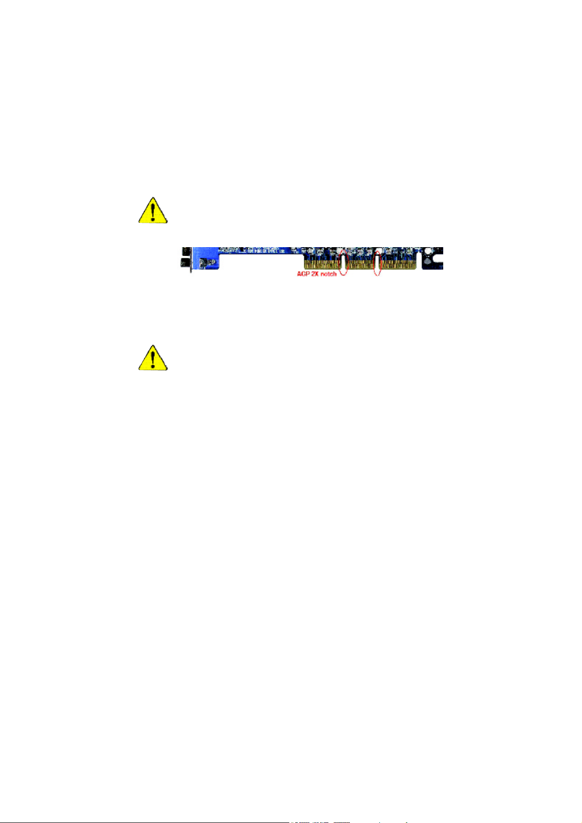
When you installing AGP card, please make sure the following notice
is fully understood and practiced. If your AGP card has "AGP 4X/8X
(1.5V) notch"(show below), please make sure your AGP card is AGP
4X/8X (1.5V).
AGP 4X/8X notch
Caution: AGP 2X card is not supported by Intel
®
845(GE/PE) / 845(E/G) /
850(E) /E7205 / 865(P/G/PE) / 875P. You might experience system unable
to boot up normally. Please insert an AGP 4X/8X card.
Example 1: Diamond Vipper V770 golden finger is compatible with 2X/4X
mode AGP slot. It can be switched between AGP 2X(3.3V) or 4X(1.5V)
mode by adjusting the jumper. The factory default for this card is 2X(3.3V).
The GA-8IPE1000MT motherboards might not function properly, if you
install this card without switching the jumper to 4X(1.5V) mode in it.
Example 2: Some ATi Rage 128 Pro graphics cards made by "Power Color",
the graphics card manufacturer & some SiS 305 cards, their golden finger is
compatible with 2X/4X mode AGP slot, but they support 2X(3.3V) only. The
GA-8IPE1000MT motherboards might not function properly, If you install this
card in it.
Note : Although Gigabyte's AG32S(G) graphics card is based on ATi Rage
128 Pro chip, the design of AG32S(G) is compliance with AGP 4X(1.5V)
specification. Therefore, AG32S(G) will work fine with Intel
®
845(GE/PE) / 845
(E/G) / 850(E) /E7205 / 865(P/G/PE) / 875P based motherboards.
8ipe1000mt_1001_f.p65 2003/4/15, 下午 05:121
The author assumes no responsibility for any errors or
omissions that may appear in this document nor does the
author make a c ommitment to update the information
contained herein.
Third-party brands and names are the property of their
respective owners.
Please do not remove any labels on motherboard, this may
void the warranty of this motherboard.
Du e to rapi d ch ange in tec hno logy , som e of the
specifications might be out of date before publication of
this booklet.
8ipe1000mt_1001_f.p65 2003/4/15, 下午 05:122

Aussch lager Weg 41, 1F, 20537 Ham burg, Germa ny
( des cription o f the appa ratus, sy stem, i nstallation to w hic h it refers)
(refere nce to the specifica ti on under wh ich conformity is de clare d)
in accor dance with 89/ 336 EEC-E MC Directive
o EN 55011 Limits and methods of measurement
o EN 55013
o EN 55014 Limits and methods of measurement
o EN 55015 Limits and methods of measurement
o EN 55020
T EN 55022 Limits and methods of measurement
o DIN VDE 0 855
o part 10
o part 12
T CE mark ing
o EN 60065
o EN 60335
of radio disturbance characte ristics of
industrial,sci entific and medical (ISM
high frequency equipment
Limits and methods of measurement
of radio disturbance characte ristics of
broadcast receivers and associated
equipment
of radio disturbance characte ristics of
household electrical appliances,
portable tools and similar electrical
apparatus
of radio disturbance characte ristics of
fluorescent lamps and luminaries
Immunity from radio interferen ce of
broadcast receivers and associated
equipment
of radio disturbance characte ristics of
information technology equipment
Cabled distrib ution systems; Equipment
for receiving and/or distr ibution fr om
sound and television signals
The manufacturer also declares the confor mity of above mentioned product
Safety requirements for mains operated
electronic and related apparatus for
household and similar general use
Safety of household and similar
electrical appliances
(Stamp)
with the actual req uired safety standar ds in accor dance with LVD 73/23 EEC
Declaration of Conformity
We, Man ufacturer /Importer
(full addr ess)
G.B.T. Technolo gy Träding GMbH
decl are that the pro duct
Mother Board
GA-8IPE 1000MT
is in conformity w ith
o EN 61000-3-2*
T EN 60555-2
o EN 61000-3-3* Disturbances in su pply systems cause
T EN 60555-3
T EN 50081-1
T EN 50082-1
o EN 55081-2
o EN 55082-2
o ENV 55104
o EN50091-2
(EC conformity marking)
o EN 60950
o EN 50091-1
Manufacturer/Impor ter
Date : April 14, 2003
Disturbances in su pply systems cause
by household appliances and similar
electrical equipment “Harmonics”
by household appliances and similar
electrical equipment “Voltage fluctuations”
Generic emission standard Part 1:
Residual commercial and light industry
Generic immunity standard Part 1:
Residual commercial and light industry
Generic emission standard Part 2:
Industrial environment
Generic emission standard Part 2:
Industrial environment
lmmunity requirements for hou sehold
appliances tools and similar apparatus
EMC requirements for uninterruptible
power syst ems (UPS)
Safety for information technology eq uipment
including electrical bussiness equipment
General and Safety requirements for
uninterruptible power syst ems (UPS)
Signature:
Name:
Timmy Huang
Timmy Huang
8ipe1000mt_1001_f.p65 2003/4/15, 下午 05:123

DECLARATION OF CONFORMITY
Per FCC Part 2 Section 2.1077(a)
Responsible Party Name:
Address:
Phone/Fax No:
hereby declares that the product
Product Name: Motherboard
Model Number: GA-8IPE1000MT
Conforms to the following specifications:
FCC Part 15, Subpart B, Section 15.107(a) and Section 15.109(a),
Class B Digital Device
Supplementary Information:
This device complies with part 15 of the FCC Rules. Operation is
subject to the following two conditions: (1) This device may not
cause harmful and (2) this device must accept any inference received,
including that may cause undesired operation.
Representative Person’s Name:
Signature:
G.B.T. INC. (U.S.A.)
17358 Railroad Street
City of Industry, CA 91748
(818) 854-9338/ (818) 854-9339
ERIC LU
Eric Lu
8ipe1000mt_1001_f.p65 2003/4/15, 下午 05:124
Date:
April. 14, 2003

GA-8IPE1000MT
P4 Titan Series Motherboard
USER'S MANUAL
Pentium® 4 Processor Motherboard
Rev. 1001
12ME-8IPE1KMT-1001

English
Item Checklist ..................................................................................... 4
Chapter 1 Introduction ........................................................................ 5
Chapter 2 Hardware Installation Process ........................................... 11
Table of Content
Features Summary ......................................................................................... 5
GA-8IPE1000M T Motherboard Layout ......................................................... 7
Block Diagram ................................................................................................ 8
Step 1: Install the Central Processing Unit (CPU) ...................................... 12
Step 1-1: CPU Installation ....................................................................................... 1 2
Step 1-2: CPU Cooling Fan Installation ................................................................... 13
Step 2: Install Memory Modules .................................................................. 14
Step 3: Install expansion cards .................................................................... 16
Step 4: Connect ribbon cables, cabinet wires and power supply............. 17
Step 4-1: I/O Back Panel Introduction ..................................................................... 1 7
Step 4-2: Connectors Introduction ........................................................................... 19
Chapter 3 BIOS Setup ......................................................................33
The Main Menu (For example: BIOS Ver. : E13) ....................................... 3 4
Standard CM OS Features ........................................................................... 3 6
Advanced BIOS Features ............................................................................. 39
Integrated Peripherals ................................................................................. 41
Power Management Setup .......................................................................... 46
PnP/PCI Configurations ................................................................................ 49
PC Health Status ........................................................................................... 5 0
- 2 -GA-8IPE1000MT Motherboard

Frequency/Voltage Control ........................................................................... 5 2
Load Fail-Safe Defaults ................................................................................ 54
Load Optimized Defaults .............................................................................. 55
Set Supervisor/User Password..................................................................... 56
Save & Exit Setup .......................................................................................... 5 7
Exit Without Saving ....................................................................................... 58
Chapter 4 Technical Reference ......................................................... 61
@BIOS™ Introduction .................................................................................... 61
EasyTune™ 4 Introduction ............................................................................ 62
Flash BIOS Method Introduction ................................................................. 63
2- / 4- / 6-Channel Audio Function Introuction ............................................ 67
Jack-Sens ing Introuct ion ........................................................................... 7 3
Chapter 5 Appendix ......................................................................... 77
English
- 3 -
Table of Content
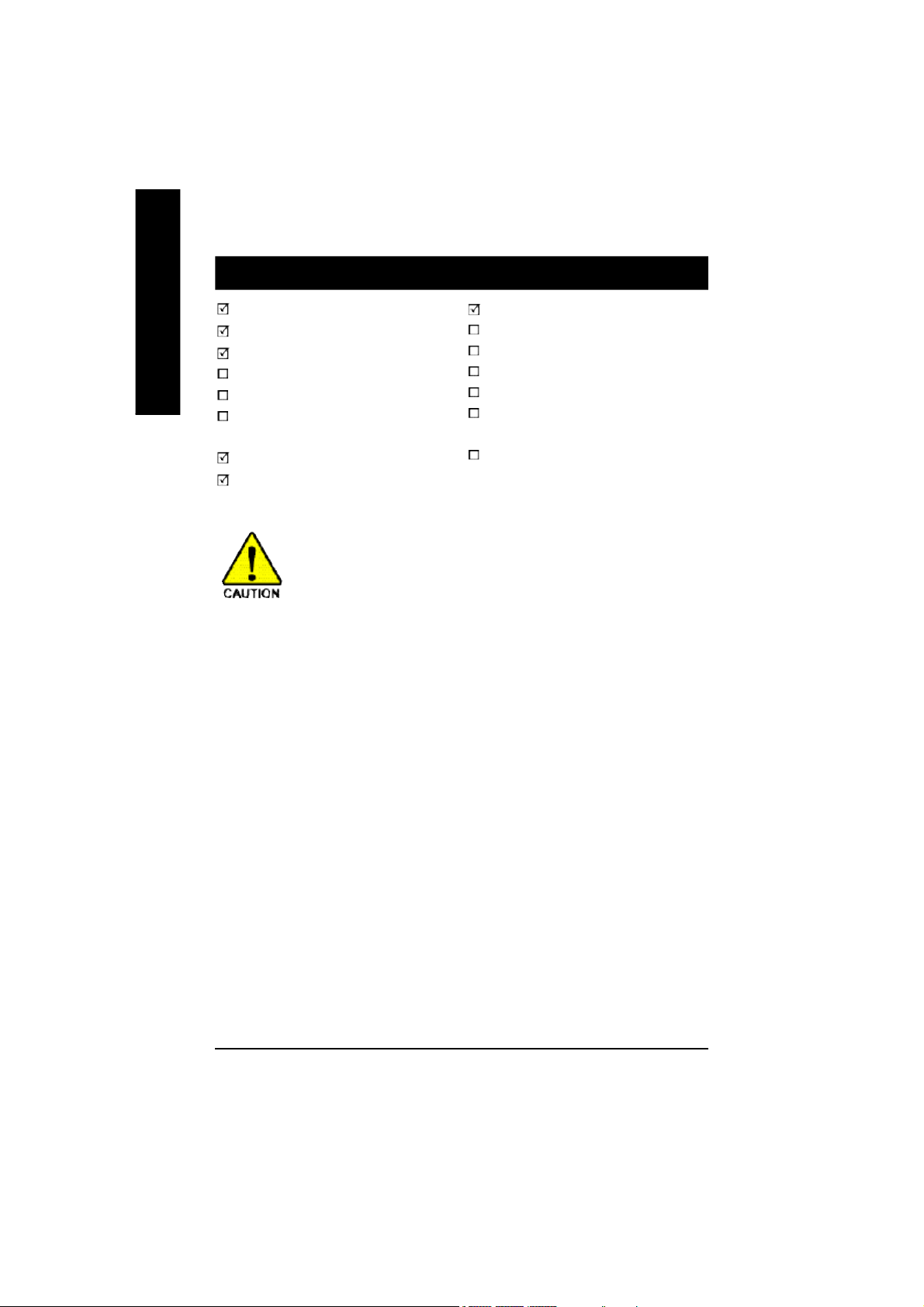
Item Checklist
English
The GA-8IPE1000MT motherboard
CD for motherboard driver & utility
GA-8IPE1000MT user's manual
Quick PC Installation Guide
SATA RAID Manual
GC-SATA Card (optional)
(M anua l; SATA c able x 1; P ower ca ble x 1)
I/O Shield
IDE cable x 1 / Floppy cable x 1
Computer motherboards and expansion cards contain very delicate Integrated Circuit
(IC) chips. To protect them against damage from static electricity, you should follow
some precautions whenever you work on your computer.
1. Unplug your computer when working on the inside.
2. Use a grounded wrist strap before handling computer components. If you do not have one, touch
both of your hands to a safely grounded object or to a metal object, such as the power supply
case.
3. Hold components by the edges and try not touch the IC chips, leads or connectors, or other
components.
4. Place components on a grounded antistatic pad or on the bag that came with the components
whenever the components are separated from the system.
5. Ensure that the ATX power supply is switched off before you plug in or remove the ATX power
connector on the motherboard.
Serial ATA cable x 2
2 Port USB Cable x 1
4 Port USB Cable x 1
SPDIF Kit x 1 (SPDIF Out Kit)
IEEE 1394 Cable x1
Audio Combo Kit x 1
(SUR ROUND- Kit + SP DIF O ut Kit)
Motherboard Settings Label
Installing the motherboard to the chassis...
If the motherboard has mounting holes, but they don't line up with the holes on the base and there are
no slots to attach the spacers, do not become alarmed you can still attach the spacers to the mounting
holes. Just cut the bottom portion of the spacers (the spacer may be a little hard to cut off, so be careful of
your hands). In this way you can still attach the motherboard to the base without worrying about short
circuits. Sometimes you may need to use the plastic springs to isolate the screw from the motherboard
PCB surface, because the circuit wire may be near by the hole. Be careful, don't let the screw contact
any printed circuit write or parts on the PCB that are near the fixing hole, otherwise it may damage the
board or cause board malfunctioning.
- 4 -GA-8IPE1000MT Motherboard

Chapter 1 Introduction
Features Summary
Form Factor — 24.4cm x 22.5cm Micro ATX size form factor, 4 layers PCB
CPU — Socket 478 for Intel® Micro FC-PGA2 Pentium® 4 processor
— Support Intel ® Pentium ® 4 (Northwood, Prescott) processor
— Support Intel® Pentium® 4 Processor with HT Technology *
— Intel® Pentium® 4 800/533/400MHz FSB
— 2nd cache depends on CPU
Chipset — Intel® Chipset 865PE HOST/AGP/Controller
— Intel® ICH5 I/O Controller Hub
Memory — 2 184-pin DDR DIMM sockets
— Supports Dual Channel DDR400/DDR333/DDR266 DIMM
— Supports 128MB/256MB/512MB/1GB unbuffered DRAM
— Supports up to 4GB DRAM (Max)
— Supports only DDR DIMM
I/O Control — ITE8712F
Slots — 3 PCI slot supports 33MHz & PCI 2.3 compliant
On-Board IDE — 2 IDE controllers provides IDE HDD/CD-ROM (IDE1, IDE2) with
PIO, Bus Master (Ultra DMA33/ATA66/ATA100) operation modes
— Can connect up to 4 IDE devices
Serial ATA — 2 Serial ATA connectors in 150 MB/s operation mode
— Controlled by ICH5
On-Board Peripherals — 1 Floppy port supports 2 FDD with 360K, 720K,1.2M, 1.44M
and 2.88M bytes
— 1 Parallel port supports Normal/EPP/ECP mode
— 2 Serial ports (COMA and COMB)
— 8 USB 2.0/1.1 ports (4 x Rear, 4 x Front by cable)
— 1 IrDA connector for IR
— 1 Front Audio connector
to be continued......
English
Due to chipset (Intel 865PE) architecture limitation, DDR 400 mem ory mod ule is only supported
when using FSB 800 Pentium 4 processor. A FSB 533 Pentium 4 processor will support
DDR3 33 an d DDR26 6 m em ory modul e. A FS B 40 0 Pentium 4 processor will only support
DDR 266 mem ory module.
- 5 -
Introduction

Hardware Monitor — CPU/System fan revolution detect
English
On-Board LAN — Builit in Realtek 8101L Chipset
On-Board Sound — Realtek ALC655 codec
PS/2 Connector — PS/2 Keyboard interface and PS/2 Mouse interace
BIOS — Licensed Phoenix BIOS, 2M bit FWH
Additional Features — PS/2 Keyboard power on by password
— CPU temperature detect
— CPU warning temperature
— System voltage detect
— CPU/System fan fail warning
— 1 RJ45 port
— Supports EZ-Jack Sensing function
— Line Out / 2 front speaker
— Line In / 2 rear speaker (by s/w switch)
— Mic In / center & subwoofer (by s/w switch)
— CD In / AUX In / Game port
— PS/2 Mouse power on
— STR (Suspend-To-RAM)
— AC Recovery
— Poly fuse for keyboard over-current protection
— USB KB/Mouse wake up from S3
— Supports @BIOS
— Supports EasyTune 4
— Supports clear password function
"*" HT functionality requirement content :
Enabling the functionality of Hyper-Threading Technology for your computer system requires all
of the following platform components:
- CPU: An Intel® Pentium 4 Processor with HT Technology
- Chipset: An Intel® Chipset that supports HT Technology
- BIOS: A BIOS that supports HT Technology and has it enabled
- OS: An operation system that has optimizations for HT Technology
Please set the CPU host frequency in accordance with your processor's specifications.
We don't recommend you to set the system bus frequency over the CPU's specification because
these specific bus frequencies are not the standard specifications for CPU, chipset and most of the
peripherals. Whether your system can run under these specific bus frequencies properly will
depend on your hardware configurations, including CPU, Chipsets, SDRAM, Cards… etc.
- 6 -GA-8IPE1000MT Motherboard
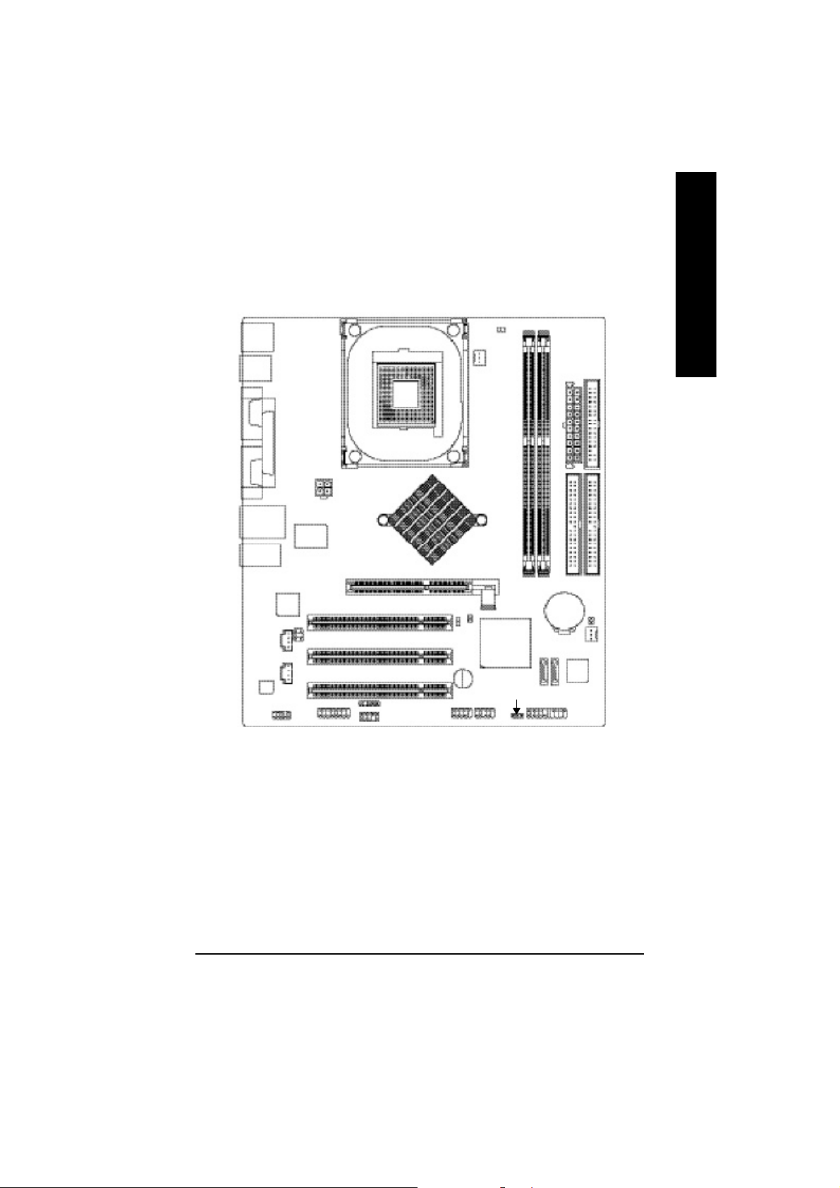
GA-8IPE1000MT Motherboard Layout
English
KB_MS
R_USB
USB
AUD IO1
CODE C
COMA
COMB
LPT
LAN
RT L
81 0 1 L
AUX_IN
F_AU DIO
ATX_12 V
ITE8712F
SUR_C EN
CD_IN
GAME
AGP
SOC KET 478
Intel 8 65PE
IR
INF O_LINK
PCI1
PCI2
PCI3
F_U SB1
CPU_FAN
2X_DET
CLR_PWD
Buzzer
F_U SB2
RAM_ LED
GA-8IPE1000MT
Intel ICH 5
PWR_ LED
DDR1
DDR2
SATA0
BAT
SATA1
ATX
IDE2
CI
SYS _FAN
BIOS
F_PANEL
FDD
IDE1
- 7 -
Introduction
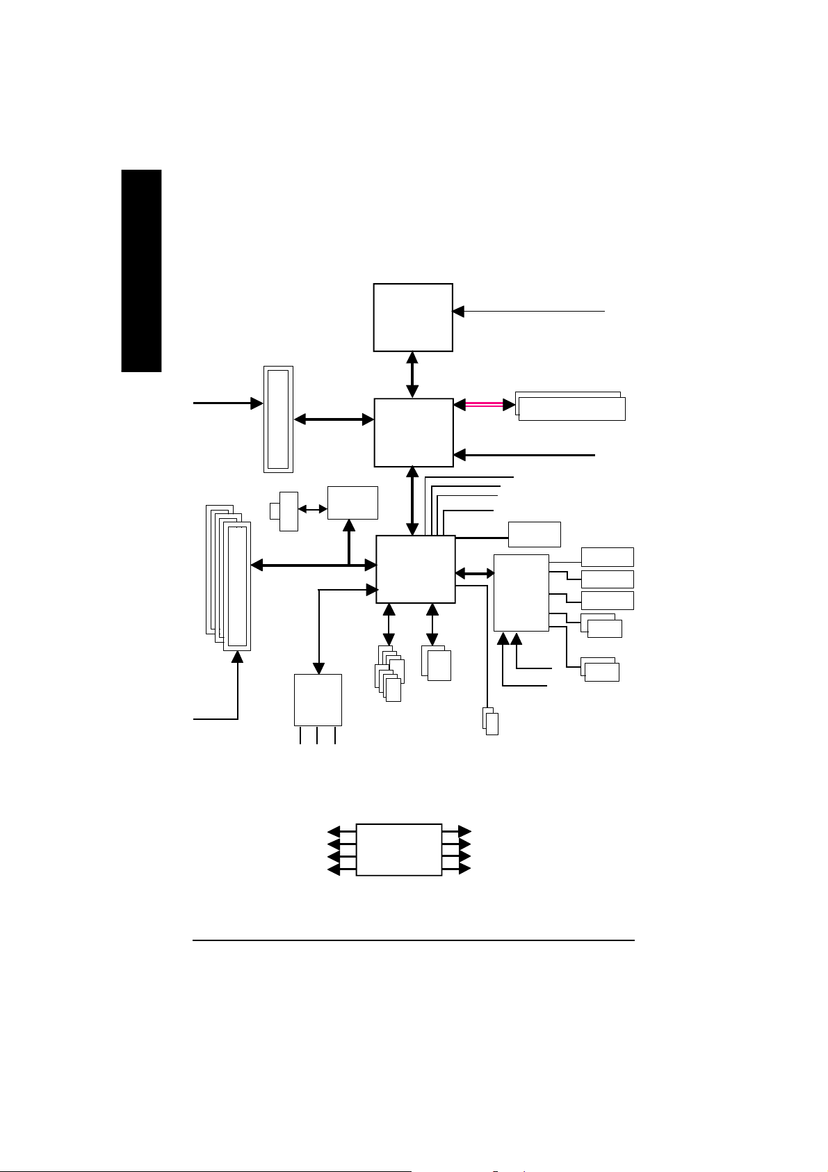
Block Diagram
English
PCICL K
(33MHz)
AGPC LK
(66MHz)
3 P CI
AGP 4X/ 8X
RJ45
AC97
CODE C
MIC
LINE-IN
Realtek
8101L
AC97 Link
LINE-OUT
Pentium 4
Socket 478
Intel 865PE
8 U SB
Ports
CP U
System Bus
800/533/400MHz
Intel
ICH5
ATA33/66/100
IDE Channels
CPUCLK+/- (10 0/133/200M Hz)
400/333/266MHz
DDR RAM
MCHCLK (100/133/200M Hz)
66 MHz
33 MHz
48 MHz
LPC BUS
14.318 MHz
BIOS
IT8712F
24 MHz
33 MHz
2 Serial ATA
Game Port
Flop py
LPT Port
PS/2 KB /Mou se
2 COM Ports
PCICLK (33M Hz)
USBCLK (48 MHz)
14.318 MHz
33 MHz
CLK GEN
- 8 -GA-8IPE1000MT Motherboard
CPUCLK+/- (10 0/133/200M Hz)
AGPCLK (66M Hz)
MCHCLK (100/133/200M Hz)
ICH3V66 (66MHz)

English
- 9 -
Introduction

English
- 10 -GA-8IPE1000MT Motherboard

Chapter 2 Hardware Installation Process
To set up your computer, you must complete the following steps:
Step 1- Install the Central Processing Unit (CPU)
Step 2- Install memory modules
Step 3- Install expansion cards
Step 4- Connect ribbon cables, cabinet wires, and power supply
Step 1
Step 4
Step 2
Step 4
English
Step 4
Step 3
Congratulations! You have accomplished the hardware installation!
Turn on the power supply or connect the power cable to the power outlet. Continue with the
BIOS/software installation.
- 11 - Hardware Installation Proc ess
Step 1: Install the Central Processing Unit (CPU)
English
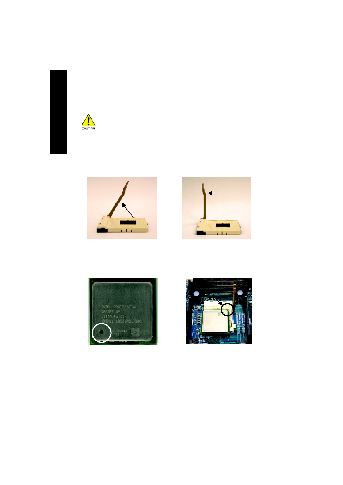
Step 1-1: CPU Installation
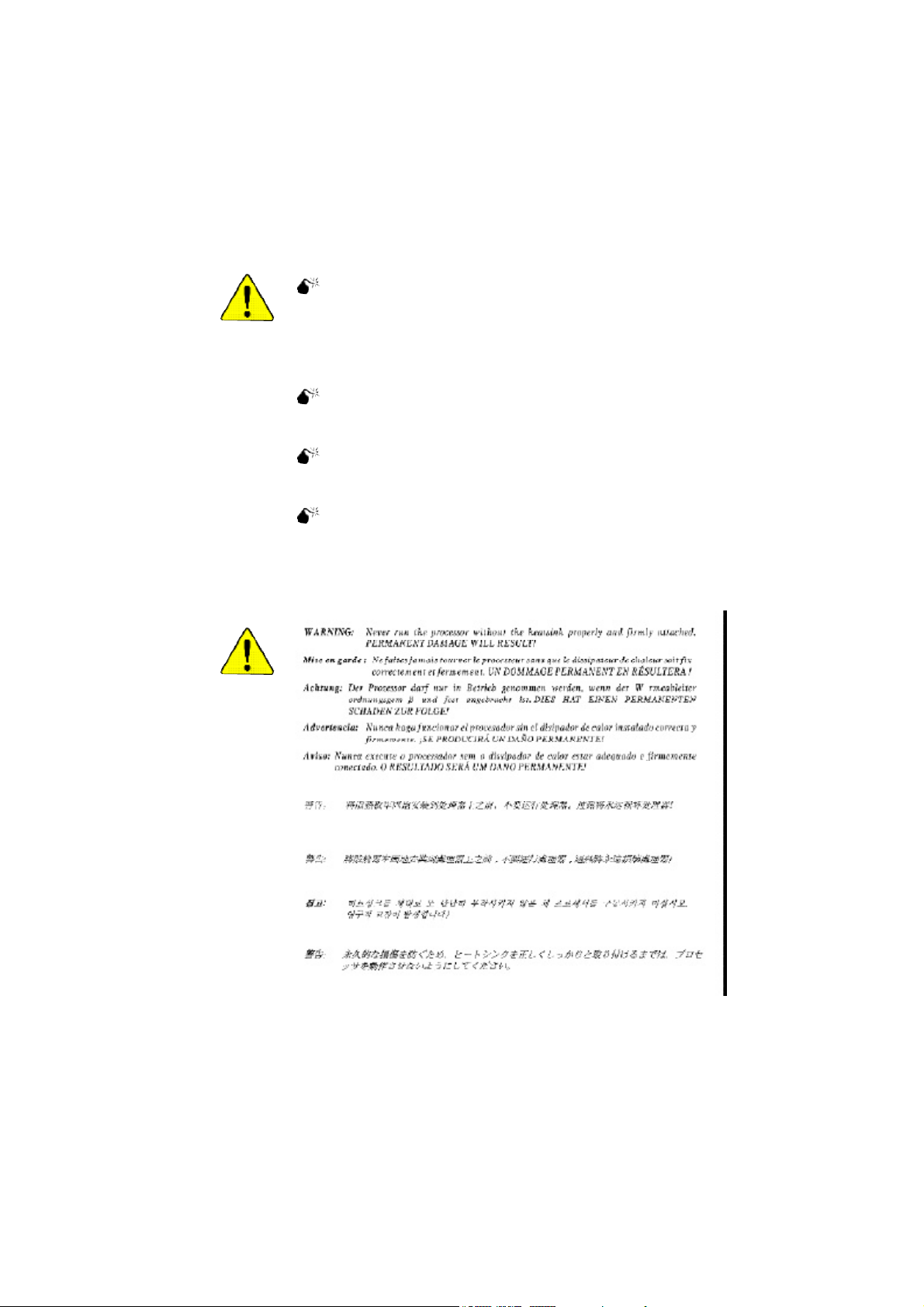
Before installing the processor, adhere to the following warning:
1. Please make sure the CPU type is supported by the motherboard.
2. If you do not match the CPU socket Pin 1 and CPU cut edge well, it will
cause improper installation. Please change the insert orientation.
Angling the
rod to 65
1. Angling the rod to 65-degree maybe
feel a kind of tight , and then continue
pull the rod to 90-degree when a noise
"cough" made.
0
Pin1 indicator
3. CPU Top View
Socket
Actuation
Lever
2. Pull the rod to the 90-degree directly.
Pin1 indicator
4. Locate Pin 1 in the socket and
look for a (golden) cut edge on the
CPU upper corner. Then insert
the CPU into the socket.
- 12 -GA-8IPE1000MT Motherboard

Step 1-2: CPU Cooling Fan Installation
Before installing the CPU cooling fan, adhere to the following warning:
1. Please use Intel approved cooling fan.
2. We recommend you to apply the thermal tape to provide better heat
conduction between your CPU and cooling fan.
(The CPU cooling fan might stick to the CPU due to the hardening of
the thermal paste. During this condition if you try to remove the cool-
ing fan, you might pull the processor out of the CPU socket alone with
the cooling fan, and might damage the processor. To avoid this from
happening, we suggest you to either use thermal tape instead of
thermal paste, or remove the cooling fan with extreme caution.)
3. Make sure the CPU fan power cable is plugged in to the CPU fan
connector, this completes the installation.
Please refer to CPU cooling fan user's manual for more detail
installation procedure.
English
1. Fasten the cooling fan supporting-
base onto the CPU socket on the
motherboard.
2. Make sure the CPU fan is plugged
to the CPU fan connector, than
install complete.
- 13 - Hardware Installation Proc ess
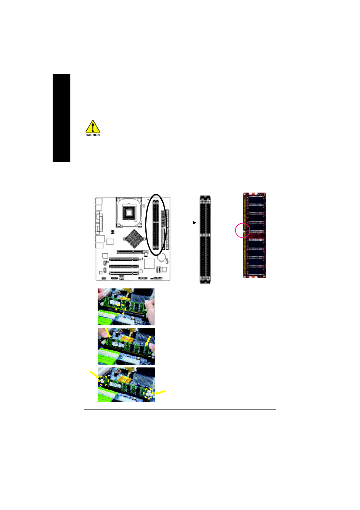
Step 2: Install Memory Modules
English
The motherboard has 2 dual inline memory module (DIMM) sockets. The BIOS will automatically
detects memory type and size. To install the memory module, just push it vertically into the DIMM
socket. The DIMM module can only fit in one direction due to the notch. Memory size can vary
between sockets.
Before installing the memory modules, adhere to the following warning:
1. When RAM LED is ON, do not install / remove DIMM from socket.
2. Please note that the DIMM module can only fit in one direction due to
the one notch. Wrong orientation will cause improper installation.
Please change the insert orientation.
Notch
DDR
1. The D IMM so cket has a no tch, s o the DIM M m emory
mo dule ca n only fit in on e direc tion.
2. Insert the DIMM m em ory modu le vertically into the DIMM
sock et. Th en pus h it down.
3. Close the plastic clip a t both edges of the DIMM socke ts
to lock the DIMM m odule.
Rever se the in stallation steps when you wish to r emo ve
the DIMM module.
- 14 -GA-8IPE1000MT Motherboard

DDR Introduction
Establishe d on the exi sting S DRAM industry in frastructure, DDR ( Double Data Rate) m emory is a
high perfor ma nce and cost-effective s olution that all ows e asy a doption for me mo ry vend ors, OEM s
and s ystem integra tors.
DDR me mo ry is a s ensi ble evolu tionar y solutio n for the P C indu stry that bui lds on the ex isting
SDRAM infrastructure, yet makes awesome advances in solving the system performance bottleneck
by doubl ing the me mory bandwidth. DDR SDRAM will offer a su perior sol ution and m igration path from
exi sting S DRA M desi gns d ue to i ts avai lab ili ty, pri cing and ove rall m arket support. PC2100 DDR
mem ory (DDR266) doubles the data rate through reading and writing at both the rising and falling edge
of the clo ck, achiev ing data ban dwidth 2 X grea ter than P C133 when runnin g with the s am e DRAM
clock frequenc y. With peak bandwidth of 2.66 4GB p er sec ond, DDR mem ory enables system OEMs
to build high pe rformance and low latency DRAM subsystem s that are suitable for server s, workstations,
high -end PC's and valu e d esktop SMA s ystem s.
Dual Channel DDR:
GA-8IPE10 00M T suppo rts Dual Channel Technolog y.
When Dual Chan nel Technolo gy is activated, the ban dwidth of m em ory b us will be d ouble
the orig inal o ne, with the fastest speed at 6. 4GB/s DDR400.
GA-8IPE1 000M T inc ludes two DIMM slots, and each Channel has 1 DIMM as following:
Channel A : DIMM 1
Channel B : DIMM 2
1. When o ne D DR m em ory mo dule i s in stalle d, the Dua l Ch anne l Tech nolo gy wil l not
oper ate. It will only work as Singl e Chan nel.
2. The Dua l Ch ann el Te chn ol ogy wi ll oper ate wh en two DDR m em or y m odu les are
installed. (Pleas e note that the two DDR m em ory m odule s mu st be the s ame mem ory
size and typ e.)
English
- 15 - Hardware Installation Proc ess
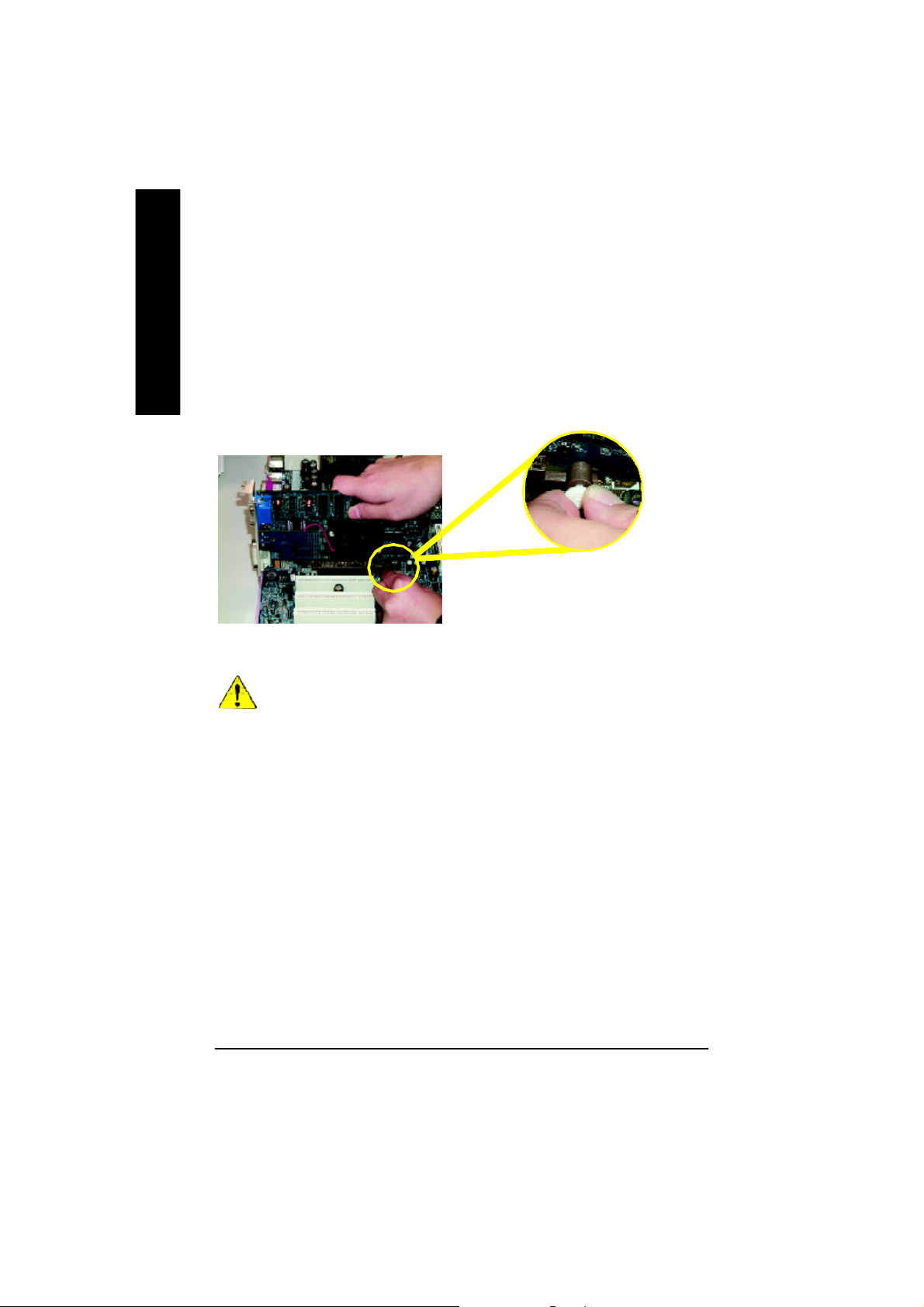
Step 3: Install expansion cards
1. Read the related expansion card's instruction document before install the expansion card into the
English
2. Remove your computer's chassis cover, screws and slot bracket from the computer.
3. Press the expansion card firmly into expansion slot in motherboard.
4. Be sure the metal contacts on the card are indeed seated in the slot.
5. Replace the screw to secure the slot bracket of the expansion card.
6. Replace your computer's chassis cover.
7. Power on the computer, if necessary, setup BIOS utility of expansion card from BIOS.
8. Install related driver from the operating system.
computer.
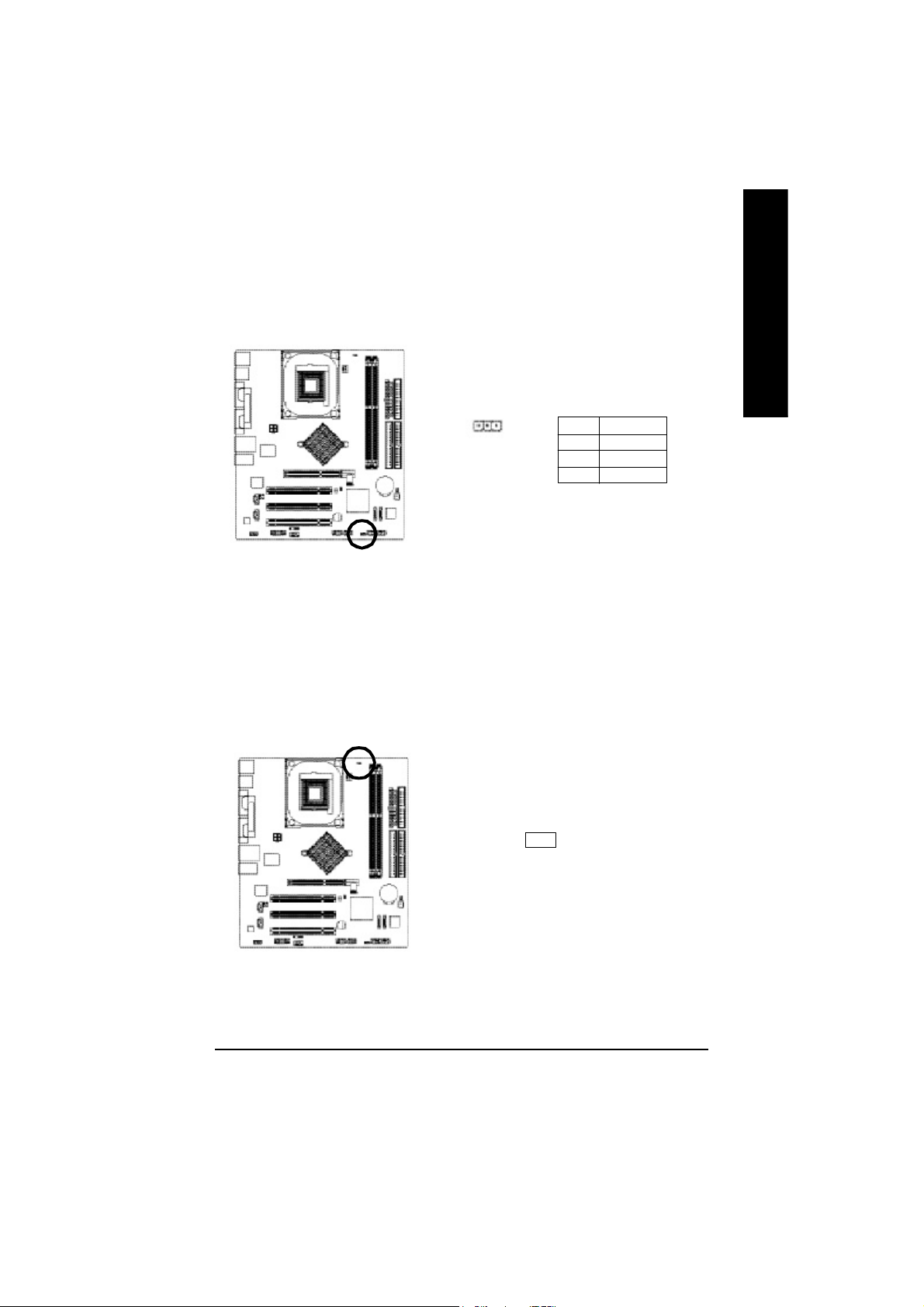
Please carefully pull ou t the sm all white-dr awable
ba r at the e nd o f the AGP slo t wh en you try to
ins tall/ U nin stall the AG P card . Ple ase ali gn the
AGP card to the onboard AGP slot and pre ss firmly
AGP Card
When an AGP 2X (3.3 V) card is installed the 2X_DET will light up, indicating a non-suppo rted
grap hics card is inser ted. Inform ing users tha t system m ight not boot up normally due to
AGP 2 X (3. 3V) is no t suppor ted by the chi pset.
down o n the slot .M ake sure your AGP card is
lock ed by the sm all white- dr awable bar.
- 16 -GA-8IPE1000MT Motherboard
Step 4: Connect ribbon cables, cabinet wires and
power supply
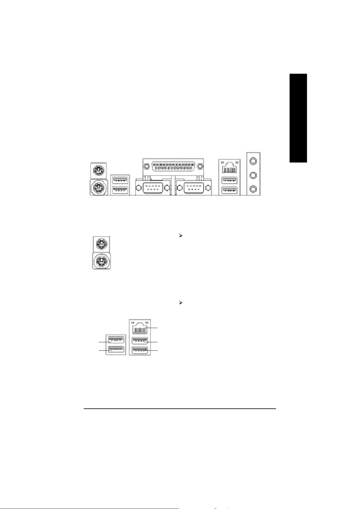
Step 4-1: I/O Back Panel Introduction
u
v
w
u PS/2 Keyboard and PS/2 Mouse Connector
x
English
y
PS/2 Mouse Connector
(6 pin Female)
PS/2 Keyboard Connector
(6 pin Female)
v/x USB/LAN Connector
USB 0
USB 1
LAN
USB 2
USB 3
This connector supports stan dard PS/2
keyboard and PS/2 mouse.
Before you connect your device(s) into USB
connector(s), please make sure your device(s)
such as USB keyboard,mouse, scanner, zip,
speaker...etc. Have a standard USB interface.
Also make sure your OS supports USB controller.
If your OS does not support USB controller, please
contact OS vendor for possible patch or driver
upgrade. For more information please contact your
OS or device(s) vendors.
- 17 - Hardware Installation Proc ess
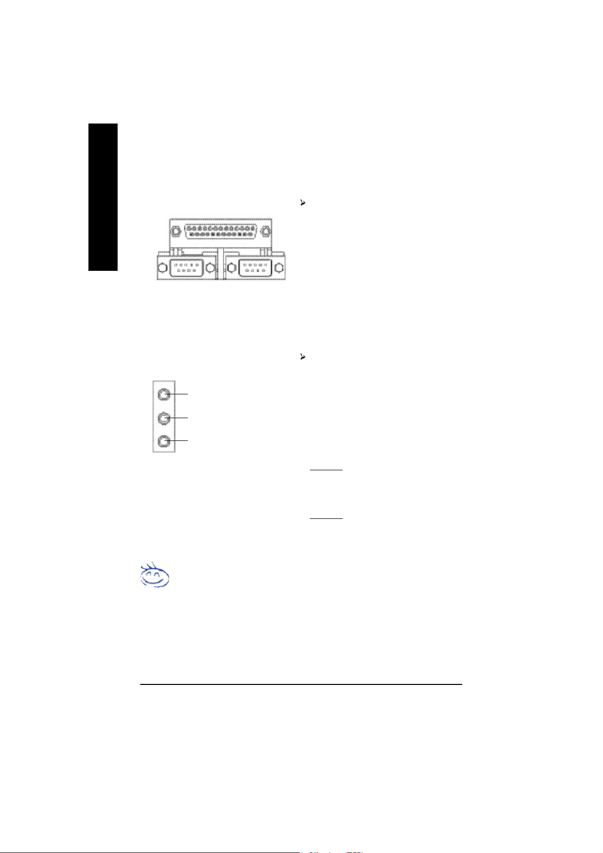
w Parallel Port, Serial Port and VGA port (LPT / COMA / VGA)
English
y Audio Connectors
Parallel Port
(25 pin Female)
COMA COMB
Serial Port (9 pin Male)
Line In (Rear Speaker)
Line Out (Front Speaker)
MIC In (Center and Subwoofer)
This connector supports 2 standard COM ports
and 1 Parallel port. Device like printer can be
connected to Parallel port; mouse and modem
etc. can be connected to Serial ports.
After install onboard audio driver, you may
connect speaker to Line Out jack, microphone to
MIC In jack. Device like CD-ROM,walkman etc.
can be connected to Line-In jack.
Please note:
You are able to use 2-/4-/6-channel audio feature
by S/W selection.
If you want to enable 6-channel function, you
have 2 choose for hardware connection.
Method1:
Connect "Front Speaker" to "Line Out"
Connect "Rear Speaker" to "Line In"
Connect "Center and Subwoofer" to "MIC Out ".
Method2:
You can refer to page 28, and contact your
nearest dealer for optional SUR_CEN cable.
If you want the detail information for 2-/4-/6-channel audio setup
installation, please refer to page 67.
- 18 -GA-8IPE1000MT Motherboard
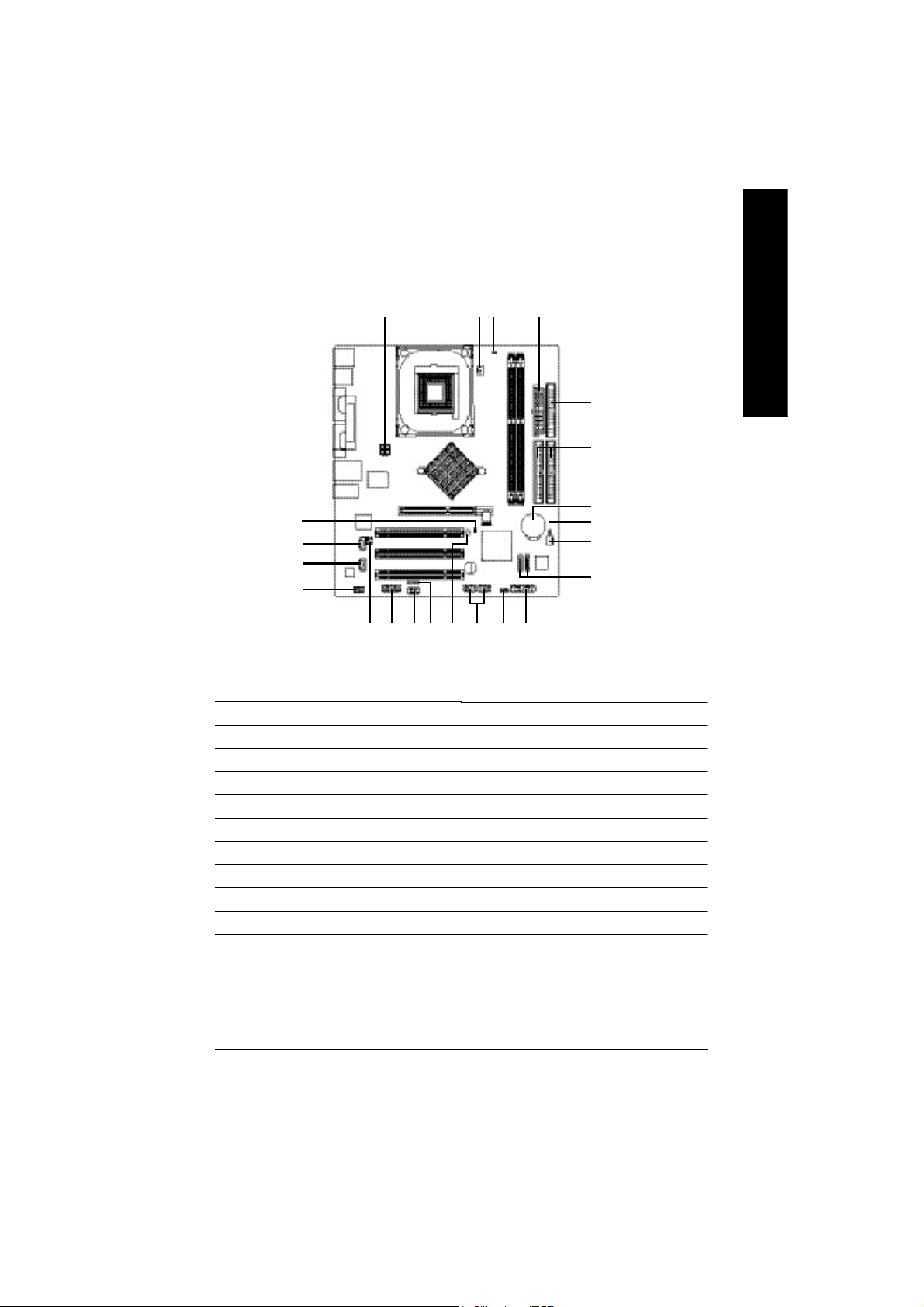
Step 4-2: Connectors Introduction
English
22
15
14
13
1) ATX_12V
2) ATX
3) CPU_FAN
4) SYS_FAN
5) FDD
6) IDE1 / IDE2
7) S_ATA1 / S_ATA2
8) BAT
9) F_PANEL
10) PWR_LED
11) RAM_LED
1 3
201118 10
19 17
16
2
12
9
12) 2X_DET
13) F_AUDIO
14) CD_IN
15) AUX_IN
16) SUR_CEN
17) F_USB1 / F_USB2
18) IR
19) GAME
20) INFO_LINK
21) CI
22) CLR_PWD
5
6
8
21
4
7
- 19 - Hardware Installation Proc ess
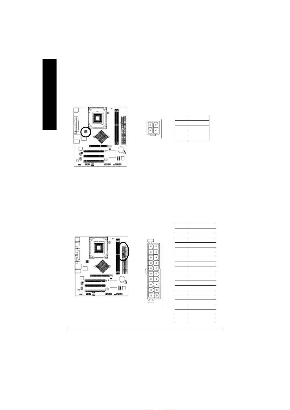
1) ATX_12V (+12V Power Connector)
English
2) ATX (ATX Power)
This c onnector ( ATX_12V) supp lies the C PU oper ation voltage (V core).
If this "ATX_1 2V con nector" i s no t connected, system c annot boo t.
Pin No. Definition
2
4
1
3
1 GND
2 GND
3 +12V
4 +12V
AC p ower cord shou ld onl y be connected to you r power s upply u nit after ATX power cab le a nd
other rela ted devices are firm ly connec ted to the main board.
Pin No . De finition
1 3.3V
2 3.3V
3 GND
11
20
1
10
4 VCC
5 GND
6 VCC
7 GND
8 Powe r Good
9 5V SB (stand by +5V)
10 +12V
11 3.3V
12 -12V
13 GND
14 PS_O N(soft on/off)
15 GND
16 GND
17 GND
18 -5V
19 VCC
20 VCC
- 20 -GA-8IPE1000MT Motherboard
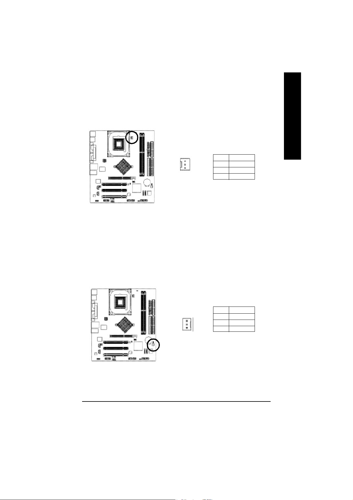
3) CPU_FAN (CPU Fan Connector)
Pleas e note, a proper ins tallation of the CPU coo ler is essential to pre vent the CPU from runni ng
unde r abn orm al con dition or dam age d by overh eating . T he C PU fan con nector supports Ma x.
current up to 600 m A.
English
1
Pin No. Definition
1 GND
2 +12V
3 Sense
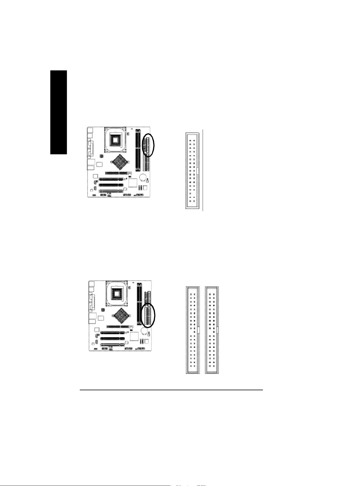
4) SYS_FAN (System Fan Connector)
Thi s conn ector allo ws y ou to l ink with the c ool ing fan on the s ystem cas e to lower the sys tem
temperature.
Pin No. Definition
1 GND
2 +12V
3 Sense
1
- 21 - Hardware Installation Proc ess
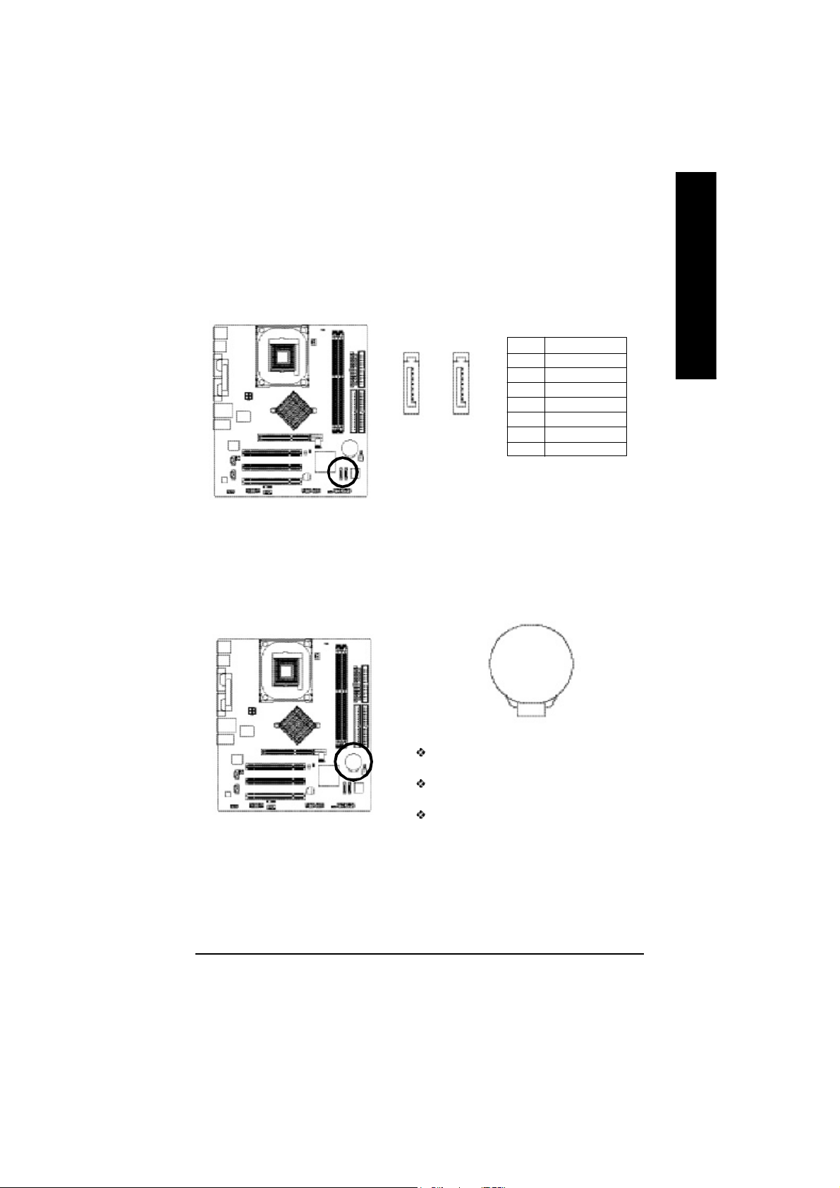
5) FDD (Floppy Connector)
English
Pleas e conne ct the floppy drive ribbon cab les to FD D. It supp orts 360K, 1.2M , 720 K, 1.44M and
2.8 8M bytes flo ppy disk typ es.
The r ed stripe of the ri bbon ca ble m ust be the sam e side with the Pin1.
34
2
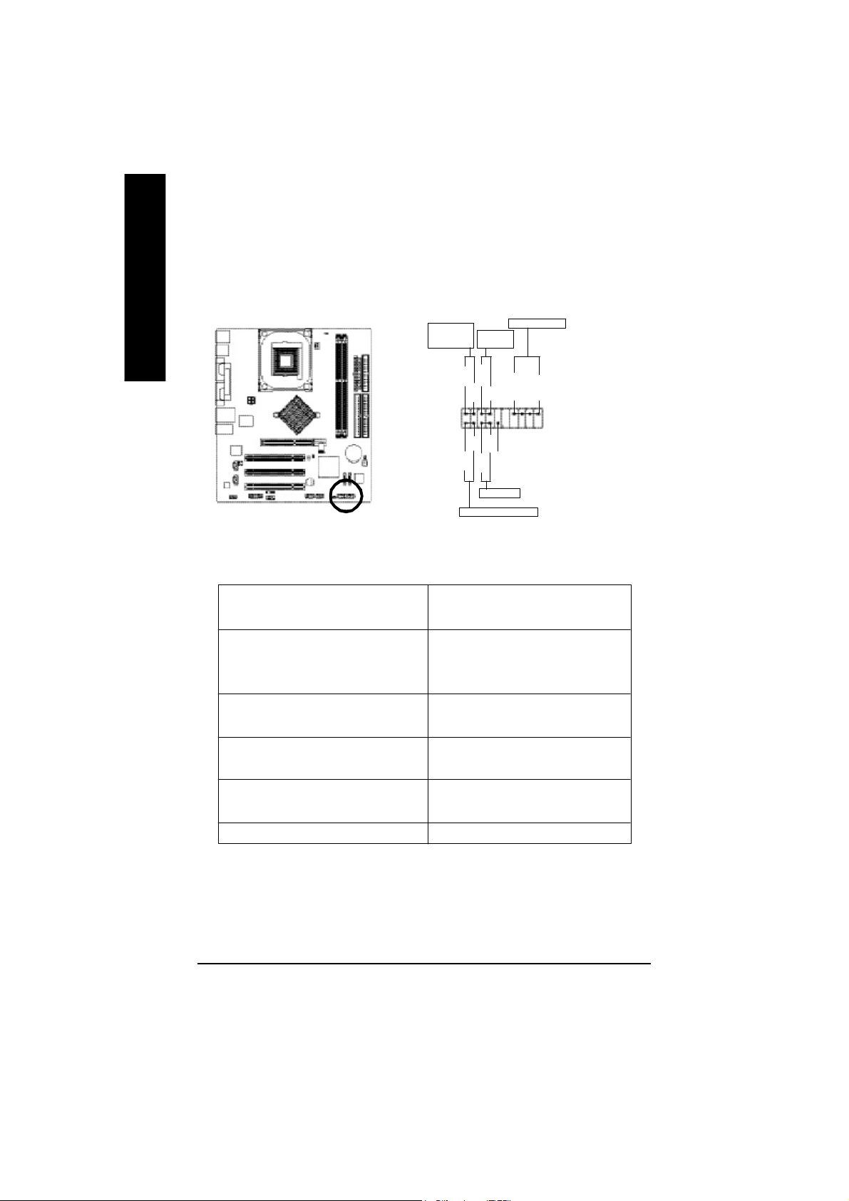
6) IDE1 / IDE2 (IDE1 / IDE2 Connector)
Impor tant Notice:
Pleas e conne ct first hard disk to IDE1 an d conne ct CD-ROM to IDE2.
The r ed stripe of the ri bbon ca ble m ust be the sam e side with the Pin1.
33
1
3940
12
IDE2
- 22 -GA-8IPE1000MT Motherboard
IDE1
7) SATA0 / SATA1 (Serial ATA Connector)
You can co nnect the S erial ATA devic e to this c onnector, it provid es you high speed transfer rates
(150M B/sec ).
English
8) BAT (BATTERY)
1
7
SATA0
1
7
SATA1
Pin No. Definition
1 GND
2 TXP
3 TXN
4 GND
5 RXN
6 RXP
7 GND
+
CAUTION
Da nge r of e xp los io n if batte ry i s inco rr ectl y
replace d.
Repl ace on ly with the s am e or equivale nt type
recom men ded by the m anufacturer.
Di sp ose of us ed b atte ri es a cc or di ng to the
ma nufacturer's i nstructions.
If you want to era se CM OS. ..
1. Turn OFF the com puter and unplug the power cord.
2. R em ove the b attery, wait for 30 sec ond.
3. R e-ins tall the battery.
4. Pl ug the power cor d and turn O N the com puter.
- 23 - Hardware Installation Proc ess
9) F_PANEL (2 x 10 pins Connector)
Please co nnect the power LED, PC sp eaker, rese t switch and power switch etc of your chassisfron t
panel to the F_ PANEL connector accordi ng to the pin as signm ent abov e.
English
Messa ge L ED/
Po wer/
Slee p LED
1 1
2
1
1
IDE H ard Disk Acti ve LE D
Sof t Po wer
Connect or
MSG+
MSG-
HD-
HD+
Res et Swi tch
PW+
RES-
PW-
1
RES+
NC
Speak er Co nnector
SPEAK+
SPEAK-
1
2 0
1 9
HD (IDE Hard Disk Active LED) Pin 1: LED anode(+)
(Blue) Pin 2: LED cathode(-)
SPK (Speaker Connector) Pin 1: V CC(+)
(Amber) Pin 2- Pin 3: NC
Pin 4: Data(-)
RES (Reset Switch) Open: Normal Operation
(Green) Close: Reset Hardware System
PW (Soft Power Connector) Open: Normal Operation
(Red) Close: Power On/Off
MSG(Message LED/ Power/ Sleep LED) Pin 1: LED anode(+)
(Yellow) Pin 2: LED cathode(-)
NC (Purple) N C
- 24 -GA-8IPE1000MT Motherboard
10) PWR_LED
PWR_ LED is con nect with the system power indica tor to ind icate whether the sys tem is on/ off.
It will bl ink when the system enters susp end m ode. If yo u use du al color LED, p ower LED will turn
to another colo r.
English
1
Pin No. Definition
1 MPD+
2 MPD-
3 MPD-
11) RAM_LED
Do not rem ove m em ory m odules while RAM _LED is on. It mig ht cause shor t or other unexpec ted
dam age s due to the s tand by vo ltage. Rem ove mem ory mo dules o nly whe n AC po wer c ord is
disco nnected.
+
_
- 25 - Hardware Installation Proc ess
 Loading...