

Page 1
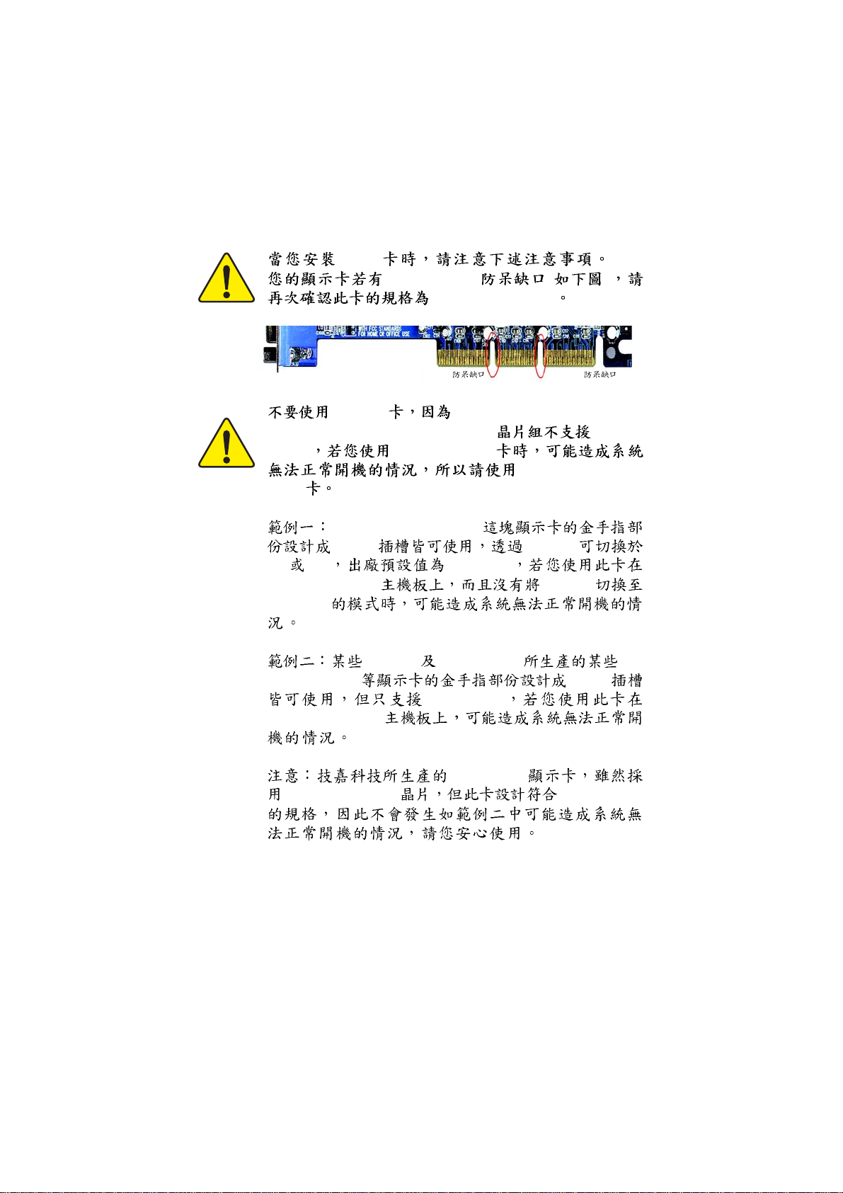
AGP
AGP 4X/8X ( )
AGP 4X/8X(1.5V)
AGP 2X
AGP 4X/8X
AGP 2X Intel® 845(GE/PE) / 845(E/G) /
850(E) / E7205 / 865(G/PE/P) / 875P
(3.3V)
AGP 2X(3.3V)
AGP 2X
AGP Pro 4X/8X
(1.5V)
Diamond Vipper V770
2X/4X Jumper
2X 4X 2X(3.3V)
GA-8IPE1000MK Jumper
4X(1.5V)
SiS 305 Power Color ATi
Rage 128 Pro
2X/4X
2X(3.3V)
GA-8IPE1000MK
AG32S(G)
ATi Rage 128 Pro AGP4X(1.5V)
Page 2
Page 3

Ausschlager Weg 41, 1F, 20537 Hamburg, Germany
( description of the apparatus, system, installation to which it refers)
(reference to the specification under which conformity is declared)
in accordance with 89/336 EEC-EMC Directive
EN 55011 Limits and methods of measurement
EN 55013
EN 55014 Limits and methods of measurement
EN 55015 Limits and methods of measurement
EN 55020
77
7 EN 55022
77
DIN VDE 0855
part 10
part 12
of radio disturbance characteristics of
industrial,scientific and medical (ISM
high frequency equipment
Limits and methods of measurement
of radio disturbance characteristics of
broadcast receivers and associated
equipment
of radio disturbance characteristics of
household electrical appliances,
portable tools and similar electrical
apparatus
of radio disturbance characteristics of
fluorescent lamps and luminaries
Immunity from radio interference of
broadcast receivers and associated
equipment
Limits and methods of measurement
of radio disturbance characteristics of
information technology equipment
Cabled distribution systems; Equipment
for receiving and/or distribution from
sound and television signals
Declaration of Conformity
We, Manufacturer/Importer
(full address)
G.B.T. Technology Träding GMbH
declare that the product
Mother Board
GA-8IPE1000MK
is in conformity with
EN 61000-3-2*
77
7 EN 60555-2
77
EN 61000-3-3* Disturbances in supply systems cause
77
7 EN 60555-3
77
77
7 EN 50081-1
77
77
7 EN 50082-1
77
EN 55081-2
EN 55082-2
ENV 55104
EN50091-2
Disturbances in supply systems cause
by household appliances and similar
electrical equipment “Harmonics”
by household appliances and similar
electrical equipment “Voltage fluctuations”
Generic emission standard Part 1:
Residual commercial and light industry
Generic immunity standard Part 1:
Residual commercial and light industry
Generic emission standard Part 2:
Industrial environment
Generic emission standard Part 2:
Industrial environment
lmmunity requirements for household
appliances tools and similar apparatus
EMC requirements for uninterruptible
power systems (UPS)
77
7 CE marking
77
EN 60065
EN 60335
(EC conformity marking)
The manufacturer also declares the conformity of above mentioned product
with the actual required safety standards in accordance with LVD 73/23 EEC
Safety requirements for mains operated
electronic and related apparatus for
household and similar general use
Safety of household and similar
electrical appliances
(Stamp)
EN 60950
EN 50091-1
Manufacturer/Importer
Date : April 14, 2003
Safety for information technology equipment
including electrical bussiness equipment
General and Safety requirements for
uninterruptible power systems (UPS)
Signature:
Name:
Timmy Huang
Timmy Huang
Page 4
DECLARA TION OF CONFORMITY
Per FCC Part 2 Section 2.1077(a)
Responsible Party Name:
Address:
Phone/Fax No:
hereby declares that the product
Product Name:
Model Number:
Conforms to the following specifications:
FCC Part 15, Subpart B, Section 15.107(a) and Section 15.109(a),
Class B Digital Device
Supplementary Information:
This device complies with part 15 of the FCC Rules. Operation is
subject to the following two conditions: (1) This device may not
cause harmful and (2) this device must accept any inference received,
including that may cause undesired operation.
Representative Person’s N ame:
Signature:
G.B.T. INC. (U.S.A.)
17358 Railroad Street
City of Industry, CA 91748
(818) 854-9338/ (818) 854-9339
Motherboard
GA-8IPE1000MK
ERIC LU
Eric Lu
Date:
April 14, 2003
Page 5

GA-8IPE1000MK
P4
c_8ipe1000mk_1003_q.p65 2005/5/13, ¤U¤È 03:451
Pentium® 4
Rev. 1003
12MC-8IPE1KMK-1003
Page 6
............................................................................ 4
....................................................................... 5
.................................................................................................... 5
GA-8IPE1000MK
Layout ........................................................... 7
................................................................................. 8
.................................................. 11
1 (CPU) ........................................................12
1-1 ................................................................................12
1-2 ...............................................................13
2 ...................................................................14
3 ............................................................................16
3-1 AGP .........................................................................................16
4 17
4-1 I/O ..........................................................................17
4-2 .....................................................................................19
BIOS .................................................. 33
(For Example BIOS Verson: F2).........................................34
CMOS .....................................................................................36
BIOS ..............................................................................39
.........................................................................................41
c_8ipe1000mk_1003_q.p65 2005/5/13, ¤U¤È 03:462
- 2 -GA-8IPE1000MK
Page 7
.........................................................................................45
PCI ...................................................................48
.........................................................................................49
/ ......................................................................................51
Fail-Safe .............................................................................53
Optimized ...........................................................................54
(Supervisor) / (User) .....................................55
SETUP ............................................................56
SETUP .......................................................57
......................................... 59
@BIOS™ .............................................................................................59
™
EasyTune
BIOS
Jack-Sensing
Xpress Recovery
4 .....................................................................................60
...............................................................................61
/ / ..................................................65
...........................................................................71
................................................................................73
..................................................................... 77
c_8ipe1000mk_1003_q.p65 2005/5/13, ¤U¤È 03:463
- 3 -
Page 8
1.
2.
3. (CPU RAM)
4.
5. ATX
PCB
c_8ipe1000mk_1003_q.p65 2005/5/13, ¤U¤È 03:464
- 4 -GA-8IPE1000MK
Page 9
y Micro ATX 24.4 x 24.4
y Socket 478 Intel Micro FC-PGA2 Pentium® 4
y Intel® Pentium® 4 (Northwood, Prescott)
y Intel® Pentium® 4 Processor with HT Technology *
®
y Intel
y 2nd
Pentium® 4 800/533/400MHz FSB
CPU
y Chipset Intel® 865PE HOST/AGP/Controller
®
y Intel
ICH5 I/O Controller Hub
y 4 184-pin DDR DIMM
y DDR400/DDR333/DDR266 DIMM
y
y
128MB/256MB/512MB/1GB unbuffered DRAM
( )
4GB
y DDR DIMM
I/O y ITE8712F
y 1 AGP 4X/8X (1.5V)
y 3 PCI 33MHz PCI 2.3 compliant
IDE y 2 IDE bus master (UDMA 33/ATA 66/ATA 100) IDE
4 ATAPI
y 1 (360K, 720K, 1.2M, 1.44M
2.88M bytes)
y 1
Normal/EPP/ECP
y 2 (COMA & COMB)
y
8 USB 2.0/1.1 USB ( x 4,
x 4)
y 1
/
y 1
(Intel 865PE) FSB800 Pntium 4
DDR400 DDR333 DDR266 FSB533 Pntium 4
DDR333 DDR266 FSB400 Pntium 4
( ) PC 4GB
4GB 4GB
c_8ipe1000mk_1003_q.p65 2005/5/13, ¤U¤È 03:465
......
DDR266
- 5 -
Page 10
y CPU /
y CPU
y CPU
y
y CPU /
y Intel® 82562 10/100
y 1 RJ45
y RealTek ALC655 CODEC
y Jack-Sensing
y Line Out : 2
y Line In : 2 ( )
y Mic In : / ( )
y CD In / AUX In / Game Port
PS/2 y PS/2 PS/2
BIOS y Phoenix BIOS, 2M bit
y Q-Flash
y PS/2
y PS/2
y STR (Suspend-To-RAM)
y AC Recovery
y
y USB / S3
y @BIOS
y EasyTune 4
™
™
y BIOS
HT :
- CPU: An Intel® Pentium 4 Processor with HT Technology
- Chipset: An Intel® Chipset that supports HT Technology
- BIOS: A BIOS that supports HT Technology and has it enabled
- OS: An operation system that has optimizations for HT Technology
CPU CPU
CPU
c_8ipe1000mk_1003_q.p65 2005/5/13, ¤U¤È 03:466
Hyper-Threading Technology
- 6 -GA-8IPE1000MK
Page 11
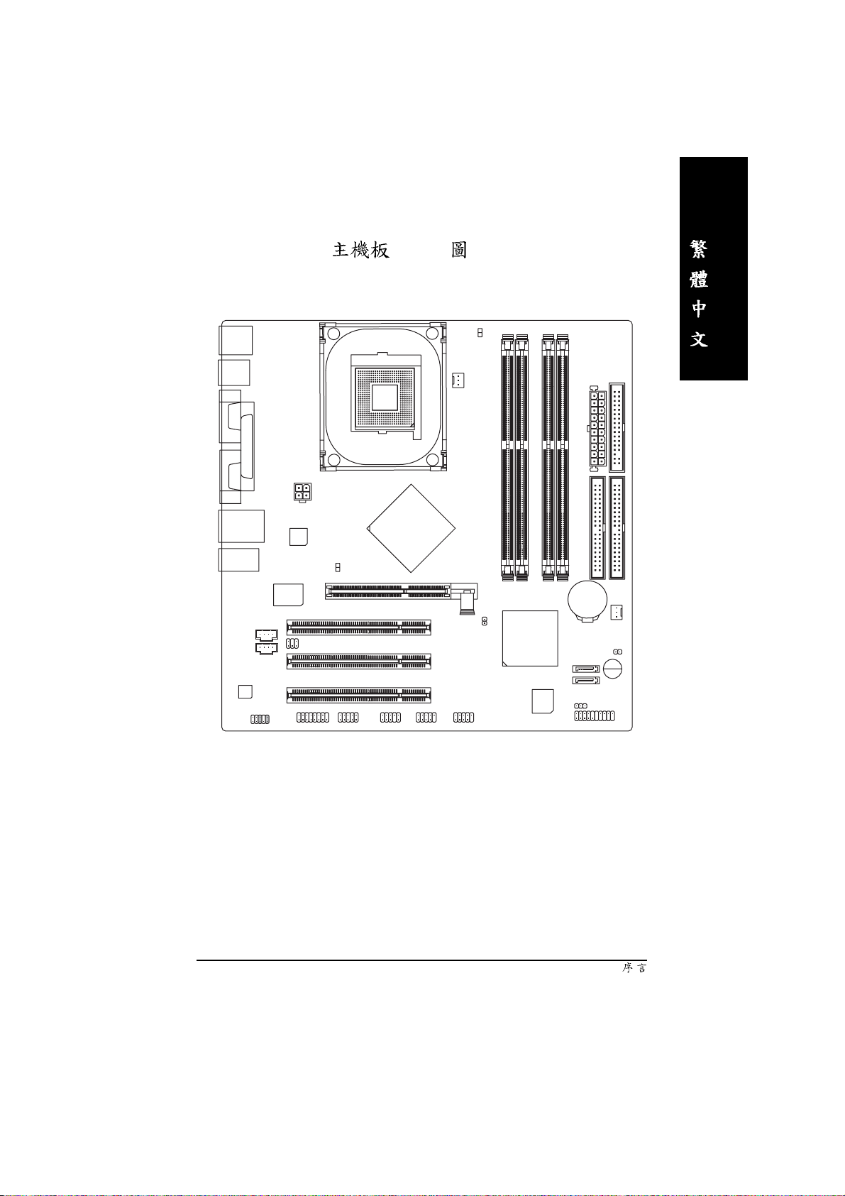
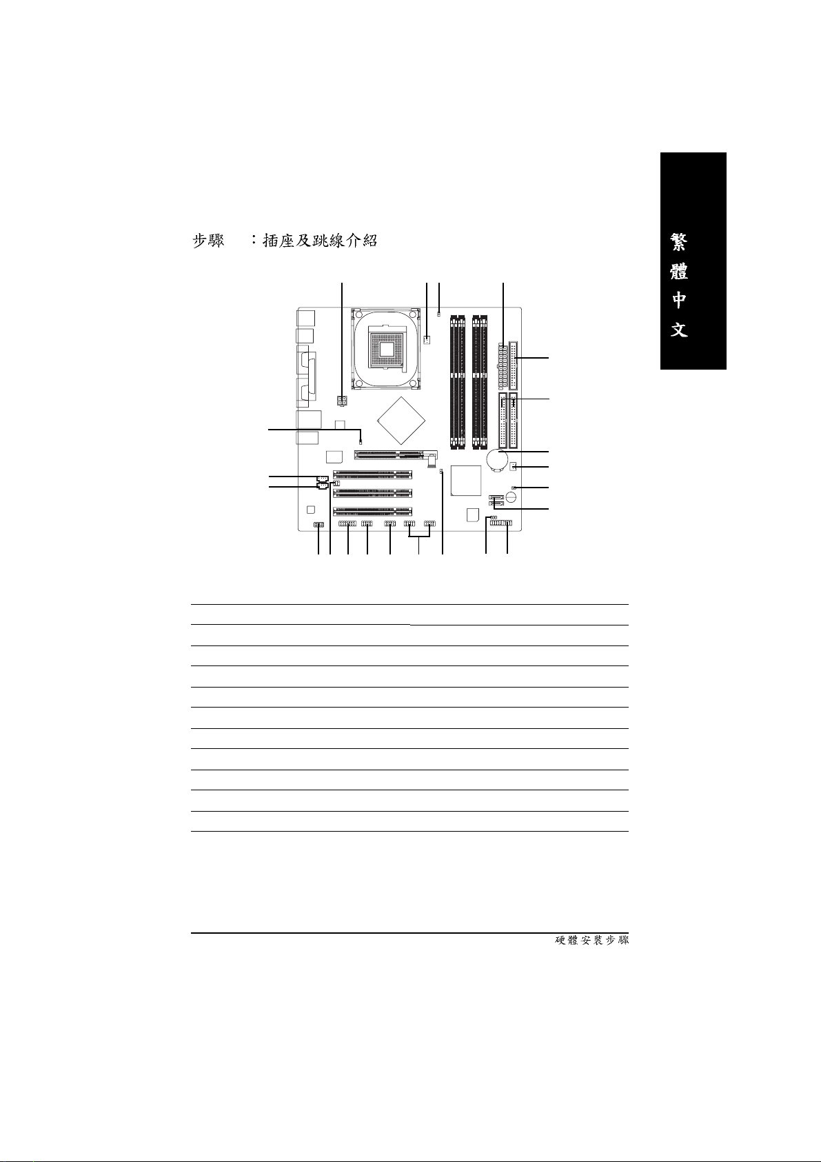
GA-8IPE1000MK Layout
KB_MS
R_USB
USB
AUDIO1
CD_IN
AUX_IN
CODEC
COMA
COMB
LPT
LAN
F_AUDIO
ATX_12V
Intel
82562EZ
2X_DET
ITE8712
AGP
SUR_CEN
GAME INFO_LINK
IR_CIR
SOCKET 478
Intel 865PE
PCI1
PCI2
PCI3
F_USB1
DIMM_LED
CPU_FAN
GA-8IPE1000MK
CLR_PWD
F_USB2
DDR1
DDR2
Intel ICH5
BIOS
DDR3
DDR4
IDE2
BAT
S_ATA1
S_ATA0
F_PANEL
ATX
SYS _FAN
CI
Buzzer
PWR_LED
FDD
IDE1
c_8ipe1000mk_1003_q.p65 2005/5/13, ¤U¤È 03:467
- 7 -
Page 12
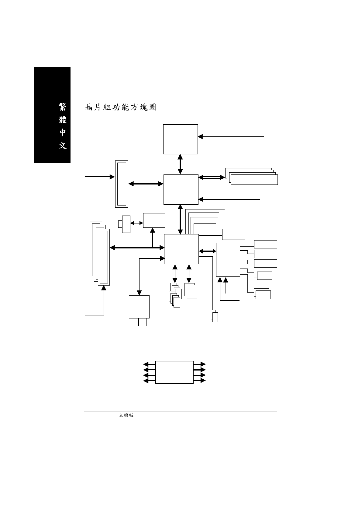
Pentium 4
Socket 478
CPU
CPUCLK+/- (100/133/200MHz)
AGPCLK
(66MHz)
3 PCI
PCICLK
(33MHz)
AGP 4X/8X
RJ45
AC97
CODEC
MIC
LINE-IN
Intel
82562EZ
AC97 Link
LINE-OUT
System Bus
800/533/400MHz
Intel 865PE
Intel
ICH5
ATA33/66/100
IDE Channels
8 USB
Ports
266/333/400MHz
MCHCLK (100/133/200MHz)
66 MHz
33 MHz
48 MHz
14.318 MHz
BIOS
LPC BUS
IT8712F
24 MHz
33 MHz
2 Serial ATA
DDR RAM
Game Port
Floppy
LPT Port
PS/2 KB/Mouse
2 COM Ports
PCICLK (33MHz)
USBCLK (48MHz)
14.318 MHz
33 MHz
c_8ipe1000mk_1003_q.p65 2005/5/13, ¤U¤È 03:468
CLK GEN
- 8 -GA-8IPE1000MK
CPUCLK+/- (100/133/200MHz)
AGPCLK (66MHz)
MCHCLK (100/133/200mHz)
ICH3V66 (66MHz)
Page 13

c_8ipe1000mk_1003_q.p65 2005/5/13, ¤U¤È 03:469
- 9 -
Page 14
c_8ipe1000mk_1003_q.p65 2005/5/13, ¤U¤È 03:4610
- 10 -GA-8IPE1000MK
Page 15
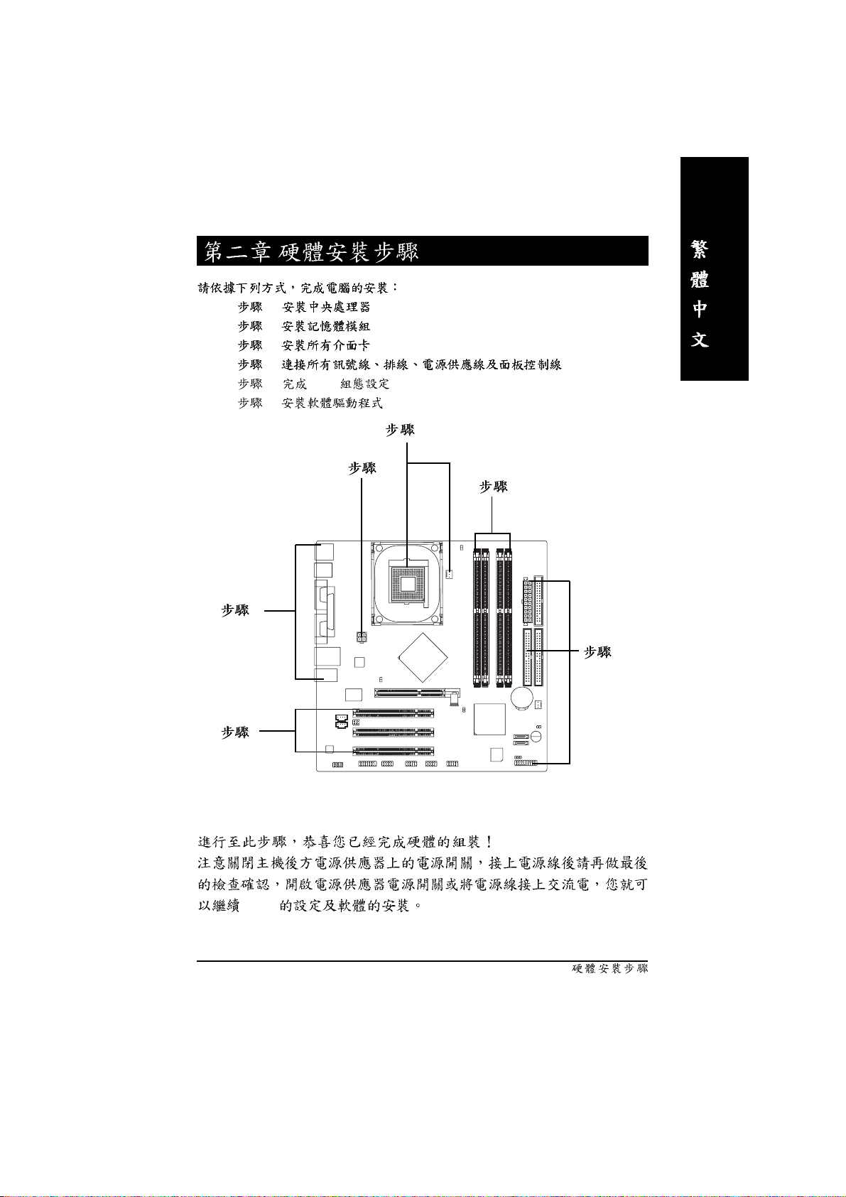
1 - (CPU)
1 - (CPU)
2 -
2 3 -
3 4 -
4 5 - BIOS
6 -
4
1
4
2
4
3
BIOS
c_8ipe1000mk_1003_q.p65 2005/5/13, ¤U¤È 03:4611
- 11 -
Page 16
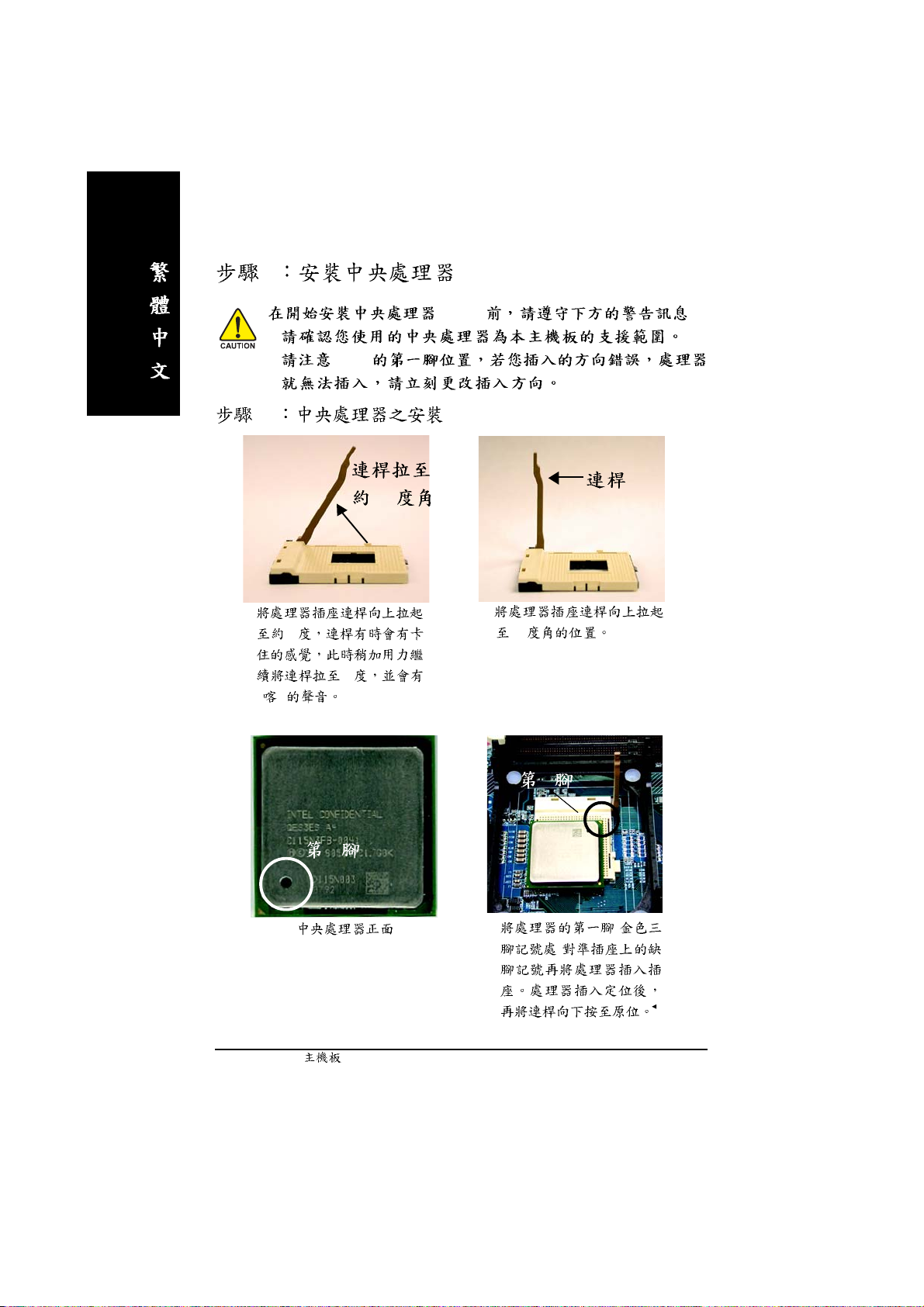
1 (CPU)
(CPU) :
1.
2. CPU
1-1
65
1.
" "
3.
65
2.
90
90
1
1
4. (
)
- 12 -GA-8IPE1000MK
c_8ipe1000mk_1003_q.p65 2005/5/13, ¤U¤È 03:4712
Page 17
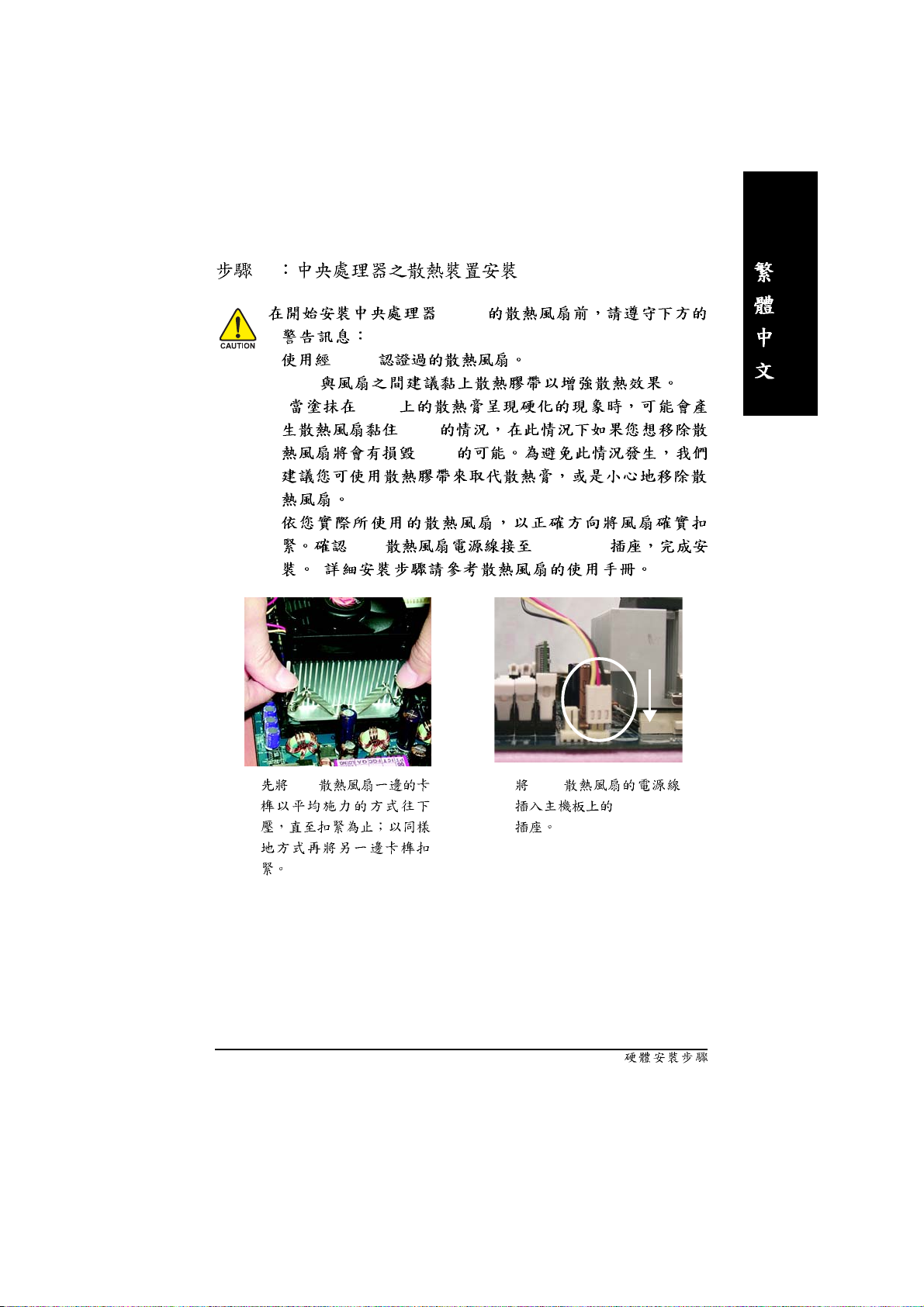
1-2
1. Intel
2.CPU
( CPU
3.
( )
(CPU)
CPU
CPU
)
CPU CPU_FAN
1. CPU 2. CPU
c_8ipe1000mk_1003_q.p65 2005/5/13, ¤U¤È 03:4713
"CPU_FAN"
- 13 -
Page 18
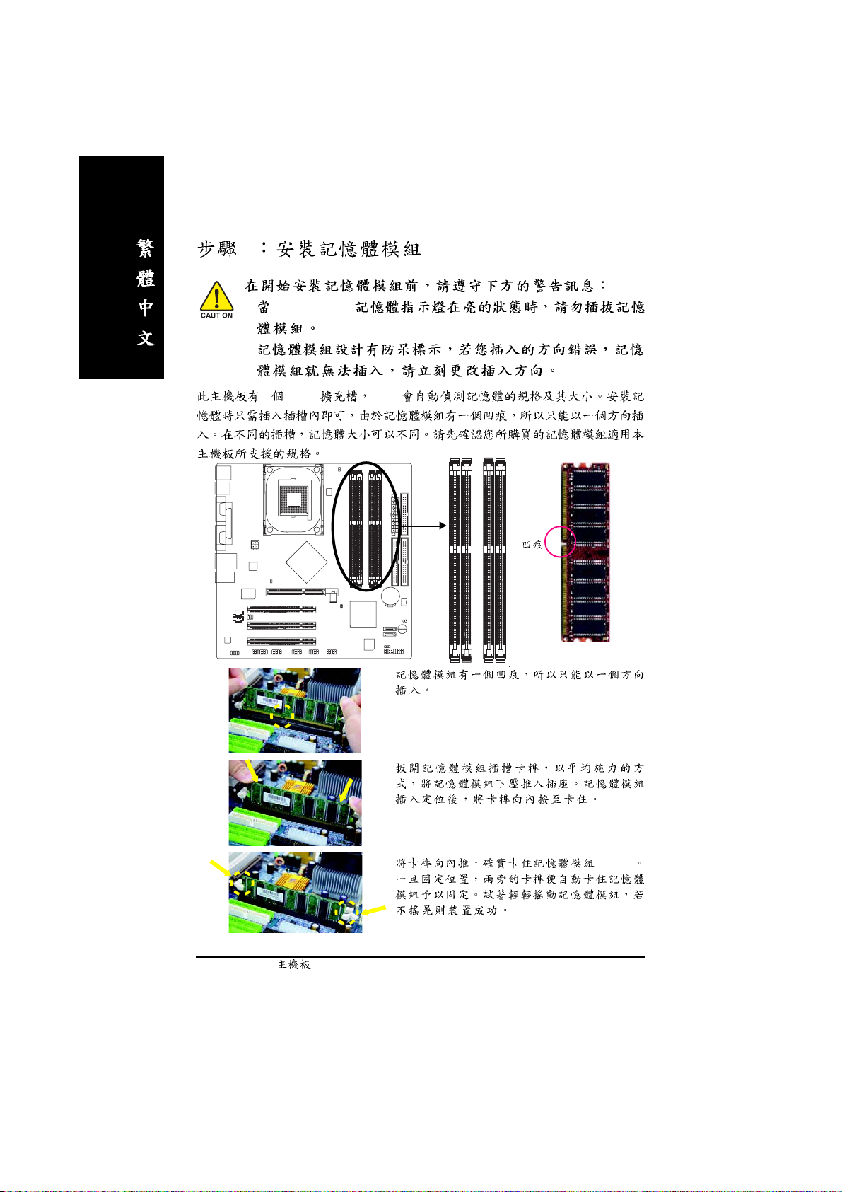
2
1. DIMM_LED
2.
4 (DIMM) BIOS
DDR
1.
c_8ipe1000mk_1003_q.p65 2005/5/13, ¤U¤È 03:4814
2.
3. DIMM
- 14 -GA-8IPE1000MK
Page 19
DDR
DDR(Double Data Rate) PC SDRAM
SDRAM
DDR OEM
DDR SDRAM
SDRAM DDR SDRAM
DDR 2.664GB/s DDR
DRAM
PC
Dual Channel DDR:
GA-8IPE1000MK Dual Channel Technology Dual Channel Technology
Memory Bus 6.4GB/s (DDR400)
GA-8IPE1000MK 4 DIMM Slot Channel 2 DIMM
Channel A : DIMM 1, 2
Channel B : DIMM 3, 4
1. DDR Dual Channel
Technology
DIMM 1 DIMM 3
2. DDR Memory size
Channel A Channel B Dual Channel
Technology
DDR Channel
Dual Channel Technology DDR
Channel A DIMM 1 DIMM 3
3. DDR Dual Channel Technology
Channel DDR
4. DDR Memory size
Channel A
Dual Channel Technology
c_8ipe1000mk_1003_q.p65 2005/5/13, ¤U¤È 03:4815
- 15 -
Page 20
Dual Channel Technology SS DS
DIMM 1 DIMM 2 DIMM 3 DIMM 4
2
4
DS/SS X DS/SS X
X DS/SS X DS/SS
DS/SS DS/SS DS/SS DS/SS
Dual Channel Technology SS DS
DIMM 1 DIMM 2 DIMM 3 DIMM 4
1
2
DS/SS X X X
X X DS/SS X
DS/SS DS/SS X X
3
3-1 AGP
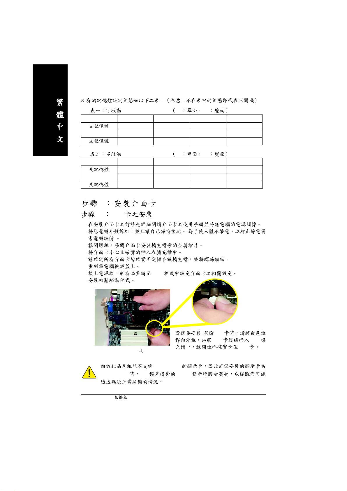
1.
2. (
)
3.
4.
5.
6.
7. BIOS
8.
AGP
AGP 2X (3.3V) AGP 2X_DET
c_8ipe1000mk_1003_q.p65 2005/5/13, ¤U¤È 03:4916
/ AGP
AGP AGP
AGP
AGP 2X (3.3V)
- 16 -GA-8IPE1000MK
Page 21
4
4-1 I/O
X
Y
\
Z
[
XX
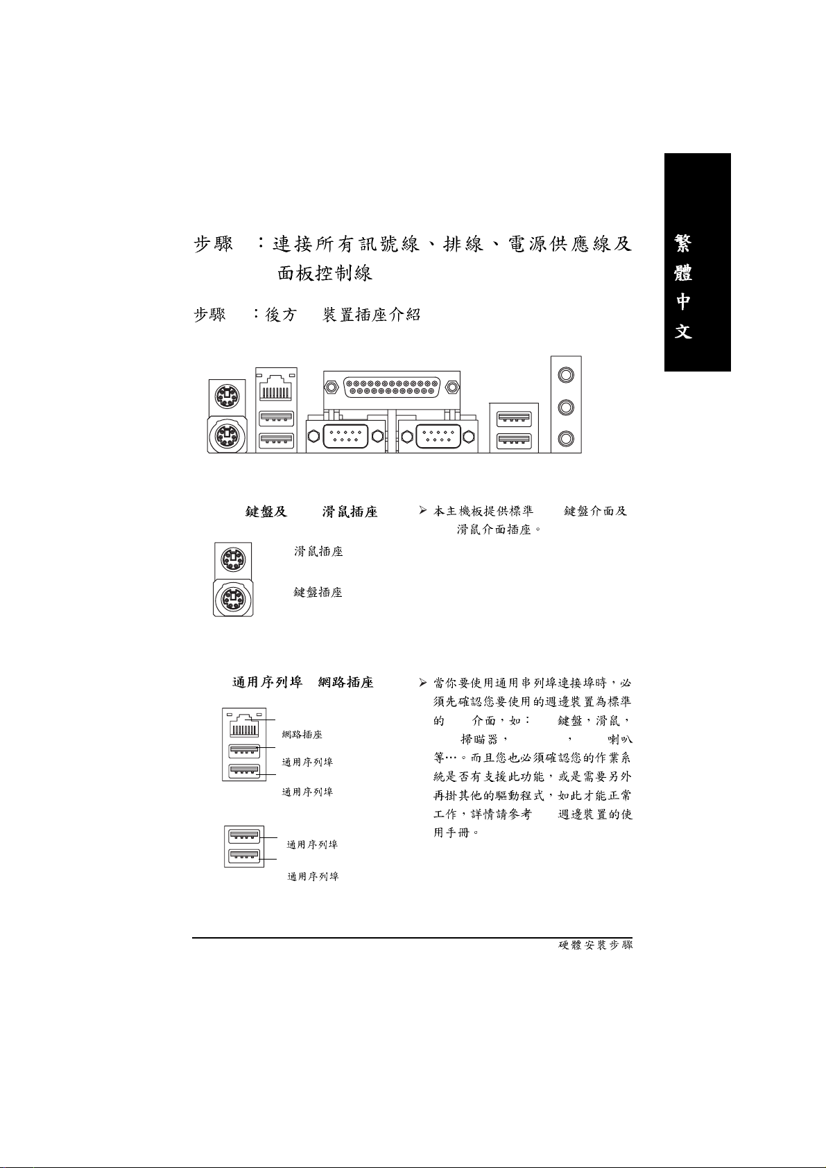
X PS/2 PS/2
XX
PS/2
(6 pin Female)
PS/2
(6 pin Female)
Y /[ /
LAN
( )
USB 2
( 2)
USB 3
( 3)
USB 0
( 0)
USB 1
( 1)
PS/2
PS/2
USB USB
USB USB ZIP USB
USB
c_8ipe1000mk_1003_q.p65 2005/5/13, ¤U¤È 03:4917
- 17 -
Page 22
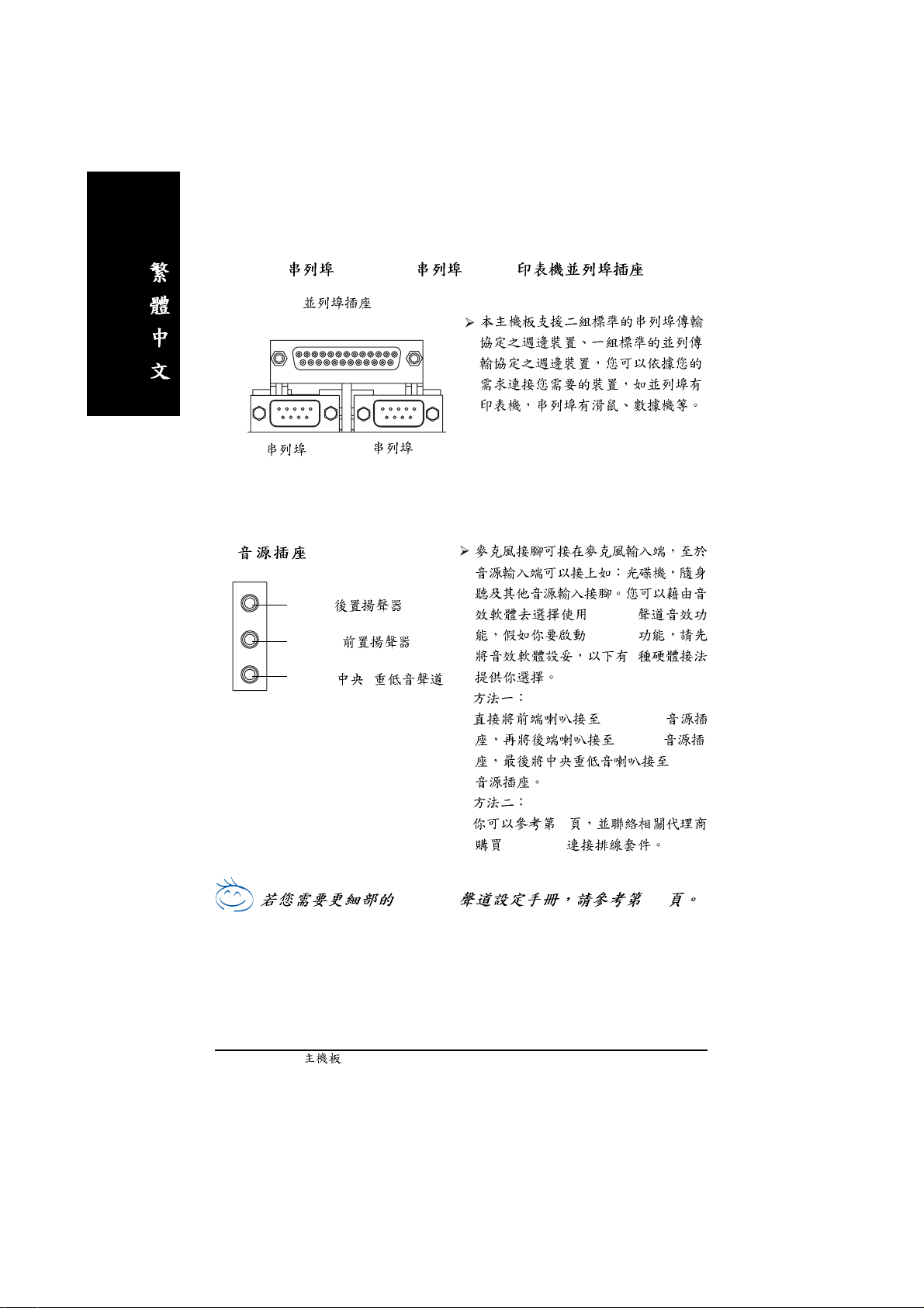
ZZ
Z COMA( A)/ COMB ( B)/LPT( )
ZZ
\\
\
\\
(25 pin Female)
A
(9 pin Male)
Line In ( )
Line Out (
MIC In ( / )
(9 pin Male)
B
2-/4-/6-
)
6-channel
2
"Line Out"
"Line In"
"Mic In"
c_8ipe1000mk_1003_q.p65 2005/5/13, ¤U¤È 03:4918
28
SUR_CEN
2-/4-/6- 65
- 18 -GA-8IPE1000MK
Page 23
4-2
12
15
1) ATX_12V
2) ATX
3) CPU_FAN
4) SYS_FAN
5) FDD
6) IDE1 / IDE2
7) SA T A0 / SA T A1
8) BAT
9) F_PANEL
10) PWR_LED
11) DIMM_LED
13
181120 22
19
17
10131416
12) 2X_DET
13) F_AUDIO
14) CD_IN
15) AUX_IN
16) SUR_CEN
17) F_USB1 / F_USB2
18) IR_CIR
19) GAME
20) INFO_LINK
21) CI
22) CLR_PWD
2
5
6
8
4
21
7
9
c_8ipe1000mk_1003_q.p65 2005/5/13, ¤U¤È 03:4919
- 19 -
Page 24
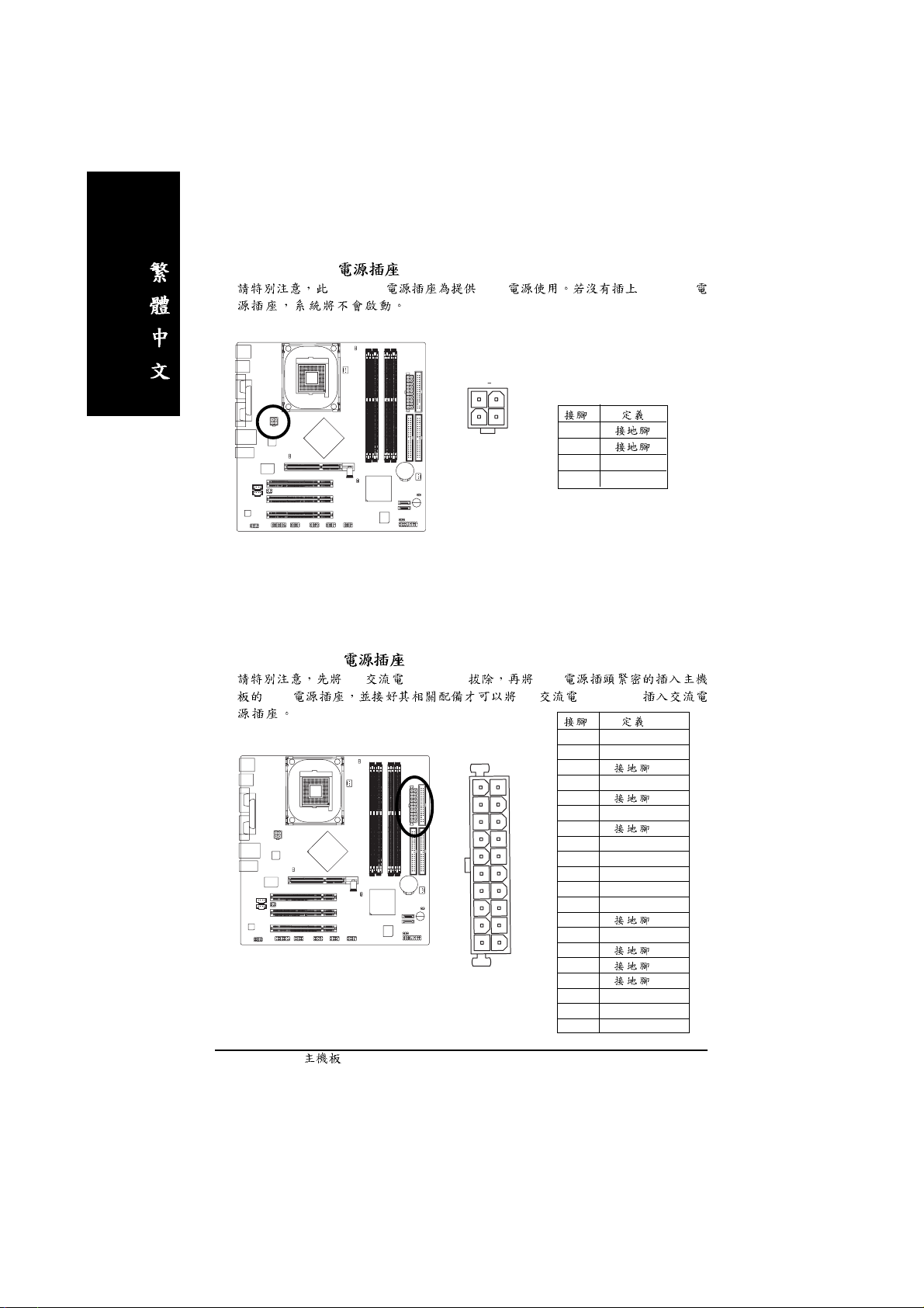
1) ATX_12V (+12V )
_
ATX_12V CPU ATX_12V
2) ATX (ATX Power )
AC (110/220V) ATX
ATX AC (110/220V)
2
4
11
20
1
3
1
10
1
2
3 +12V
4 +12V
1 3.3V
2 3.3V
3
4 VCC
5
6 VCC
7
8 Power Good
9 5V SB (stand by +5V)
10 +12V
11 3.3V
12 -12V
13
14 PS_ON(soft on/off)
15
16
17
18 -5V
19 VCC
20 VCC
- 20 -GA-8IPE1000MK
c_8ipe1000mk_1003_q.p65 2005/5/13, ¤U¤È 03:5020
Page 25

3) CPU_FAN (CPU )
CPU 600
4) SYS_FAN ( )
AGP PCI
1
1
2 +12V
3 Sense
1
2 +12V
3 Sense
1
c_8ipe1000mk_1003_q.p65 2005/5/13, ¤U¤È 03:5121
- 21 -
Page 26
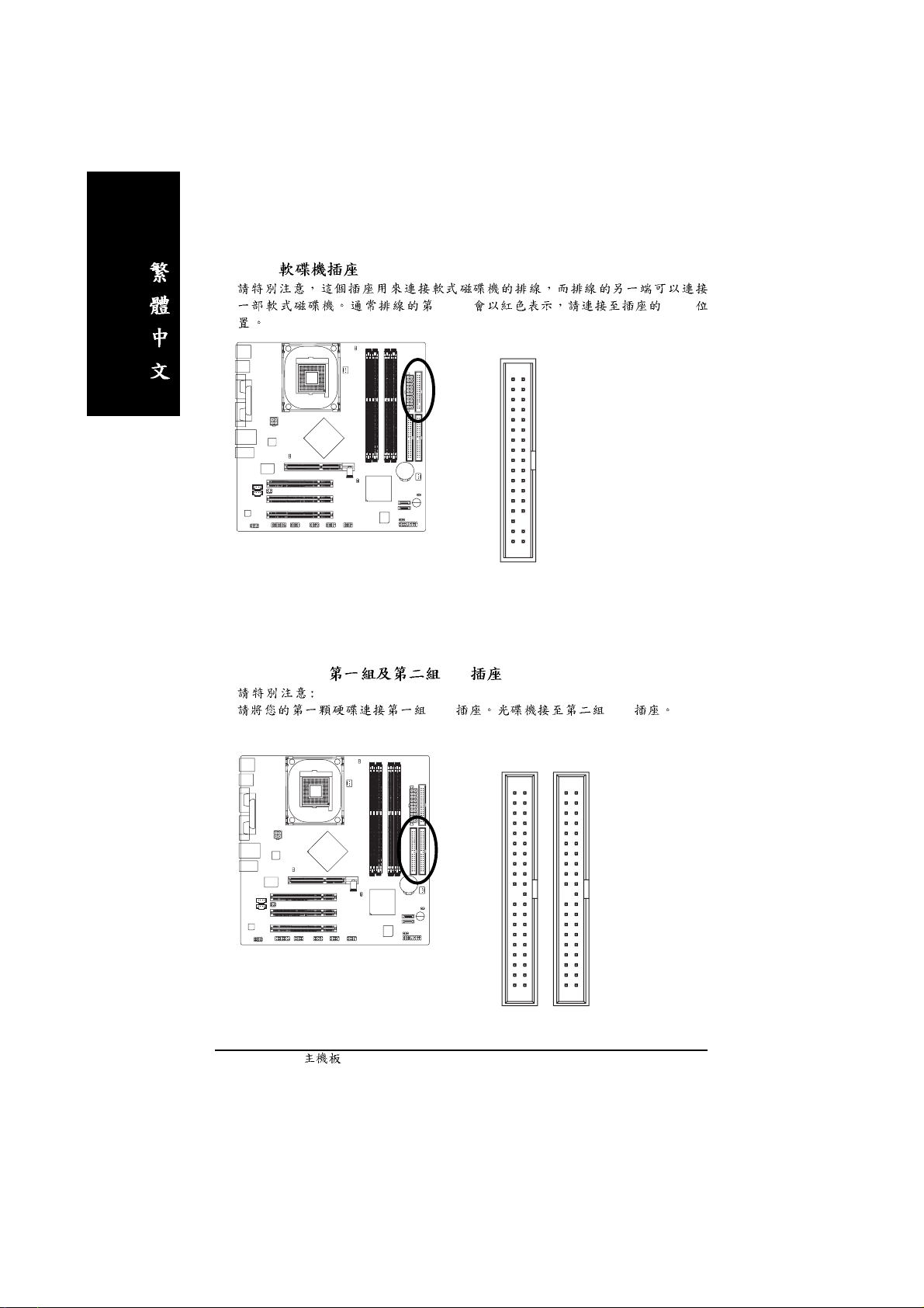
5) FDD ( )
1 Pin Pin1
34
2
6) IDE1 / IDE2 ( IDE )
IDE IDE
33
1
3940
c_8ipe1000mk_1003_q.p65 2005/5/13, ¤U¤È 03:5222
12
IDE2
- 22 -GA-8IPE1000MK
IDE1
Page 27
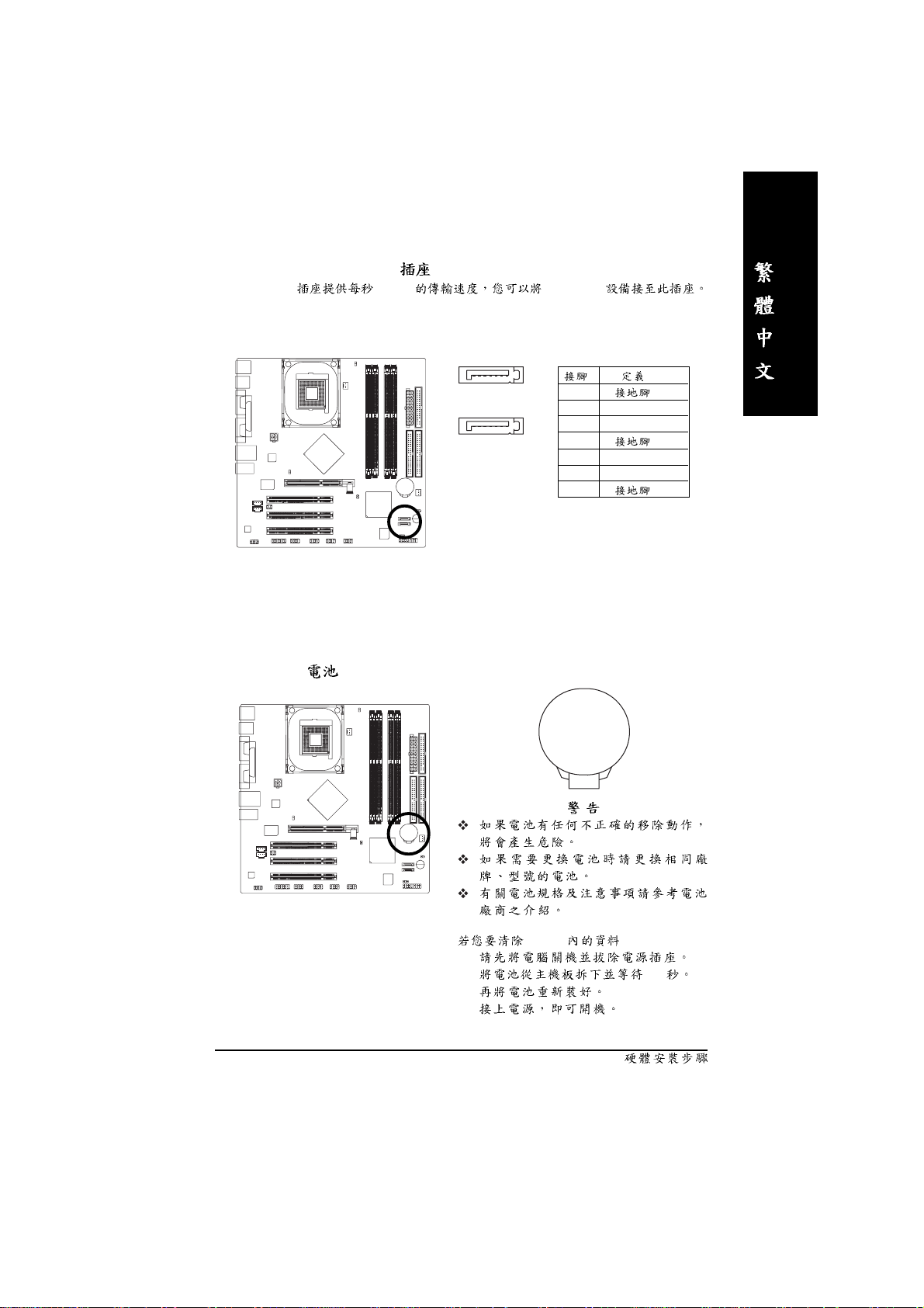
7) SATA0 / SATA1 (Serial ATA )
Serial ATA 150MB Serial ATA
8) BATTERY ( )
7
SATA1
SATA0
1
1
2 TXP
17
3 TXN
4
5 RXN
6 RXP
7
+
c_8ipe1000mk_1003_q.p65 2005/5/13, ¤U¤È 03:5423
CMOS ...
1.
2. 30
3.
4.
- 23 -
Page 28
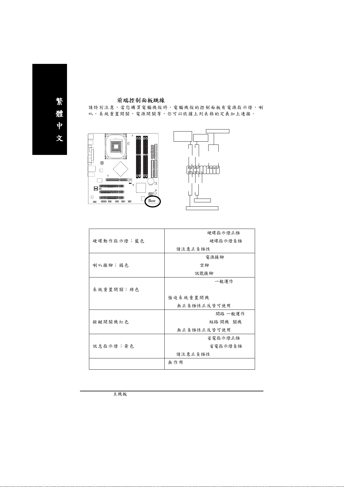
9) F_PANEL ( )
MSG+
MSG-
HD-
HD+
Soft Power
Connector
PW+
PW-
1
1
RES-
NC
RES+
Reset Switch
Speaker Connector
SPEAK+
1
Message LED/
Power/
Sleep LED
1
2
1
1
IDE Hard Disk Active LED
HD (IDE Hard Disk Active LED) Pin 1: LED anode(+)
Pin 2: LED cathode(-)
SPK (Speaker Connector) Pin 1: VCC(+) +5v
Pin 2- Pin 3: NC
Pin 4: Data(-)
RES (Reset Switch) Open: Normal Operation
Close: Reset Hardware System
SPEAK-
20
19
PW (Soft Power Connector) Open: Normal Operation :
MSG (Message LED/Power/Sleep LED) Pin 1: LED anode(+)
NC
c_8ipe1000mk_1003_q.p65 2005/5/13, ¤U¤È 03:5524
Close: Power On/Off : /
Pin 2: LED cathode(-)
- 24 -GA-8IPE1000MK
Page 29
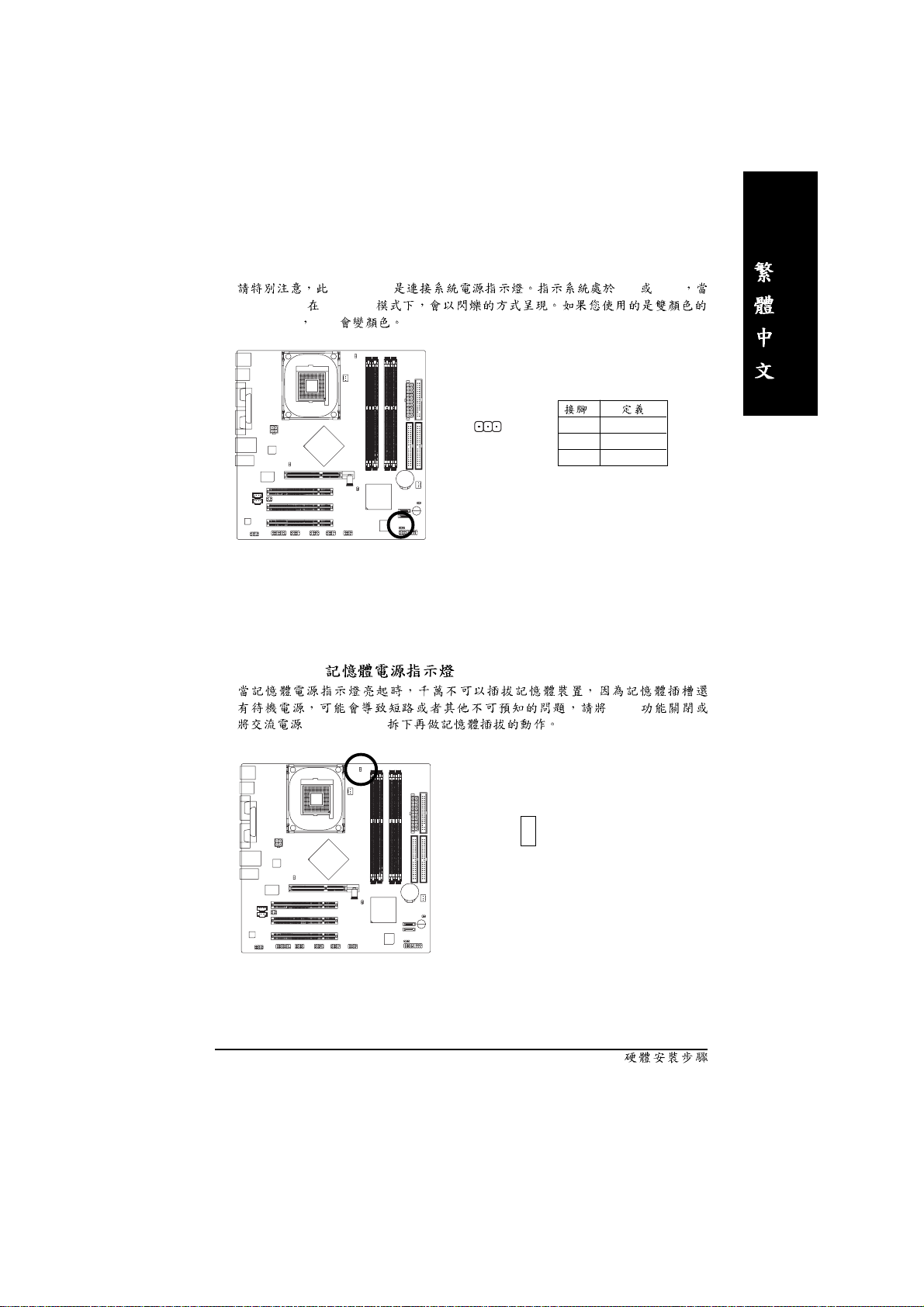
10) PWR_LED
Power LED Suspend
power LED LED
PWR_LED ON OFF
11)DIMM_LED ( )
(AC110/220V)
1
1 MPD+
2 MPD3 MPD-
STR
_
+
c_8ipe1000mk_1003_q.p65 2005/5/13, ¤U¤È 03:5625
- 25 -
Page 30

12)2X_DET (AGP 2X )
2X(3.3V) 2X_DET
2X(3.3V)
13) F_AUDIO ( )
_
+
Jumper
c_8ipe1000mk_1003_q.p65 2005/5/13, ¤U¤È 03:5726
Pin5-6 Pin9-10
1 MIC
10
2
9
1
2
3 REF
4
5 Front Audio (R)
6 Rear Audio (R)
7 Reserved
8
9 Front Audio (L)
10 Rear Audio (L)
- 26 -GA-8IPE1000MK
Page 31

14)CD_IN ( )
CD-ROM DVD-ROM CD
15)AUX_IN ( )
1
1
2
3
4
MPEG
c_8ipe1000mk_1003_q.p65 2005/5/13, ¤U¤È 03:5927
1
- 27 -
1
2
3
4
Page 32

16)SUR_CEN ( )
652
1
17) F_USB1 / F_USB2 ( )
USB USB
USB
SUR_CEN
1 SUR OUTL
2 SUR OUTR
3
4
5 CENTER_OUT
6 BASS_OUT
c_8ipe1000mk_1003_q.p65 2005/5/13, ¤U¤È 04:0028
F_USB1
- 28 -GA-8IPE1000MK
2
1
10
F_USB2
9
1
2
3 USB Dx4 USB Dy5 USB Dx+
6 USB Dy+
7
8
9
10
10
2
1
9
Page 33

18)IR_CIR ( / )
IR Pin1
Pin5
610
15
19) GAME ( )
IR
1 +5V
2
3
4
5
6
7
8 +5V
9
10
c_8ipe1000mk_1003_q.p65 2005/5/13, ¤U¤È 04:0129
2
1
- 29 -
1
2 GRX1_R
3
16
15
4 GPSA2
5
6 GPX2_R
7 GPY2_R
8 MSI_R
9 GPSA1
10
11 GPY1_R
12
13 GPSB1
14 MSO_R
15 GPSB2
16
Page 34

20)INFO_LINK
21) CI ( )
1 SMBCLK
102
1
9
2
3 SMBDATA
4 GPIO
5
6
7
8
9 +12V
10 +12V
c_8ipe1000mk_1003_q.p65 2005/5/13, ¤U¤È 04:0230
1
1
2
- 30 -GA-8IPE1000MK
Page 35

22) CLR_PWD
Jumper open BIOS (
User password Supervisor password) Jumper close
1
1
Open:
Close:
c_8ipe1000mk_1003_q.p65 2005/5/13, ¤U¤È 04:0331
- 31 -
Page 36

c_8ipe1000mk_1003_q.p65 2005/5/13, ¤U¤È 04:0332
- 32 -GA-8IPE1000MK
Page 37

BIOS
AWARD BIOS CMOS SETUP
CMOS SETUP CMOS SRAM
CMOS SRAM
BIOS POST Power On Self Test
Del AWARD BIOS CMOS SETUP
BIOS BIOS "Ctrl+F1"
< >
< >
< >
< >
<Enter>
<Esc> SETUP
<Page Up>
<Page Down>
<F1>
<F2>
<F3>
<F4>
<F5> ( )
<F6> Fail-Safe ( )
<F7> Optimized ( )
<F8> Q-Flash
<F9>
<F10> CMOS SETUP
BIOS- 33 -
Page 38

SETUP
SETUP
F1
BIOS CMOS SETUP
<Esc>
(For Example BIOS Verson: F2)
CMOS SETUP ,
, Enter
CMOS Setup Utility-Copyright (C) 1984-2003 Award Software
` Standard CMOS Features
` Advanced BIOS Features
` Integrated Peripherals
` Power Management Setup
` PnP/PCI Configurations
` PC Health Status
` Frequency/Voltage Control
ESC: Quit KLJI: Select Item
F8: Q-Flash F10: Save & Exit Setup
Time, Date, Hard Disk Type...
1
BIOS
zz
z Standard CMOS Features ( CMOS )
zz
zz
z Advanced BIOS features ( BIOS )
zz
Load Fail-Safe Defaults
Load Optimized Defaults
Set Supervisor Password
Set User Password
Save & Exit Setup
Exit Without Saving
BIOS
"Ctrl+F1"
- 34 -GA-8IPE1000MK
Page 39

zz
z Integrated peripherals ( )
zz
COM Port IRQ LPT
Port
zz
z Power management setup ( )
zz
CPU GREEN
zz
z PnP/PCI configuration ( PCI )
zz
ISA PnP PCI
zz
z PC Health Status ( )
zz
,
zz
z Frequency/Voltage Control ( / )
zz
CPU
zz
z Load Fail-Safe defaults ( Fail-Safe )
zz
zz
z Load Optimized defaults ( Optimized )
zz
zz
z Set Supervisor password ( )
zz
zz
z Set User password ( )
zz
zz
z Save & exit setup ( )
zz
zz
z Exit without save ( SETUP )
zz
SPP EPP ECP IDE PIO Mode
BIOS CMOS
Optimized CMOS
SETUP CMOS
PC BIOS
SETUP BIOS
F10
<ESC>
BIOS- 35 -
Page 40

CMOS
CMOS Setup Utility-Copyright (C) 1984-2003 Award Software
Standard CMOS Features
Date (mm:dd:yy) Fri, Mar 28 2003 Item Help
Time (hh:mm:ss) 22:31:24 Menu Level X
Change the day, month,
`IDE Primary Master [None] year
`IDE Primary Slave [None]
`IDE Secondary Master [None] <Week>
`IDE Secondary Slave [None] Sun. to Sat.
Drive A [1.44M, 3.5"] <Month>
Drive B [None] Jan. to Dec.
Floppy 3 Mode Support [Disabled]
<Day>
Halt On [All, But Keyboard] 1 to 31 (or maximum
allowed in the month)
Base Memory 640K
Extended Memory 111M <Year>
Total Memory 112M 1999 to 2098
KLJI: Move Enter:Select +/-/PU/PD:Value F10:Save ESC:Exit F1:General Help
F5:Previous Values F6:Fail-Safe Defaults F7:Optimized Defaults
Date(mm:dd:yy) ( )
(mm) 1 12
(dd) 1 28/29/30/31
(yy) 1999 2098
2 CMOS
/ /
/ /
- 36 -GA-8IPE1000MK
Page 41

Time(hh:mm:ss) ( )
24
13 : 00 : 00 RTC
IDE Primary Master (Slave) / IDE Secondary Master (Slave)
( / )
IDE
1 IDE 2
CMOS
1 User TYPE CYLS HEADS
SECTORS MODE
2 AUTO TYPE MODE AUTO BIOS POST
IDE
Capacity MegaBytes)
Access Mode CHS/ LBA/ Large/ Auto
Cylinder
Head
Precomp Write precomp
Landing Zone Landing Zone
Sector Number of sectors ( )
"NONE" <Enter>
Drive A / Drive B ( A:/ B: )
None
360K, 5.25" 5.25 360KB
1.2M, 5.25" 5.25 1.2MB
720K, 3.5" 3 720KB
1.44M, 3.5" 3 1.44MB
2.88M, 3.5" 3 2.88MB
Floppy 3 Mode Support ( 3 Mode )
Disabled 3 Mode ( )
Drive A A: 3 Mode
Drive B B: 3 Mode
Both A: B: 3 Mode
BIOS- 37 -
Page 42

Halt on ( )
POST
All Errors
No Errors
All, But Keyboard ( )
All, But Diskette
All, But Disk/Key
Memory ( )
BIOS POST(Power On Self Test)
STANDARD CMOS SETUP
Base Memory
PC 640KB MS-DOS
Extended Memory
Base Other Memory
Module
- 38 -GA-8IPE1000MK
Page 43

BIOS
CMOS Setup Utility-Copyright (C) 1984-2003 Award Software
Advanced BIOS Features
First Boot Device [Floppy]
Second Boot Device [HDD-0]
Third Boot Device [CDROM]
Password Check [Setup]
# CPU Hyper-Threading [Enabled]
KLJI: Move Enter:Select +/-/PU/PD:Value F10:Save ESC:Exit F1:General Help
F5:Previous Values F6:Fail-Safe Defaults F7:Optimized Defaults
3 BIOS
" # " Intel® Pentium® 4 processor with HT Technology
Item Help
Menu Level X
Select Boot Device
Priority
[Floppy]
Boot from floppy
[LS120]
Boot from LS120
First / Second / Third Boot device ( / / )
Floppy
LS120 LS120
HDD-0~3
SCSI SCSI
CDROM
LAN
USB-CDROM USB-CDROM
USB-ZIP USB-ZIP
USB-FDD USB-FDD
USB-HDD USB-HDD
ZIP ZIP
Disabled
BIOS- 39 -
Page 44

Password Check ( )
Setup CMOS SETUP
Setup CMOS SETUP ( )
SETUP
Enter
CPU Hyper-Threading
Enabled CPU Hyper Threading
Disabled
#
( )
" # " Intel® Pentium® 4 processor with HT Technology
- 40 -GA-8IPE1000MK
Page 45

CMOS Setup Utility-Copyright (C) 1984-2003 Award Software
Integrated Peripherals
On-Chip Primary PCI IDE [Enabled]
On-Chip Secondary PCI IDE [Enabled]
On-Chip SATA [Auto]
x SATA Port0 Configure as SATA Port0
SATA Port1 Configure as SATA Port1
USB Controller [Enabled]
USB 2.0 Controller [Enabled]
USB Keyboard Support [Disabled]
USB Mouse Support [Disabled]
AC97 Audio [Auto]
Onboard H/W LAN [Enabled]
Onboard Serial Port 1 [3F8/IRQ4]
Onboard Serial Port 2 [2F8/IRQ3]
UART Mode Select [Normal]
x UR2 Duplex Mode Half
Onboard Parallel Port [378/IRQ7]
Parallel Port Mode [SPP]
x ECP Mode Use DMA 3
Game Port Address [201]
Midi Port Address [330]
Midi Port IRQ [10]
Item Help
Menu Level X
If a hard disk
controller card is
used, set at Disabled
[Enabled]
Enabled onboard IDE
Port
[Disabled]
Disabled onboard IDE
Port
KLJI: Move Enter:Select +/-/PU/PD:Value F10:Save ESC:Exit F1:General Help
F5:Previous Values F6:Fail-Safe Defaults F7:Optimized Defaults
4
BIOS- 41 -
Page 46

On-Chip Primary PCI IDE ( channel PCI IDE )
Enabled channel IDE ( )
Disabled
On-Chip Secondary PCI IDE ( channel IDE )
Secondary IDE
Enabled channel PCI IDE ( )
Disabled
On-chip SATA
Disabled
Auto IDE1 IDE2 SATA IDE
Manual ( )
SATA Port 0 Configure as ( SATA )
"On-chip SATA" "Manual"
IDE Pri. Master SATA Port 0 IDE Pri. Master
IDE Pri. Slave SATA Port 0 IDE Pri. Slave
IDE Sec. Master SATA Port 0 IDE Sec. Master
IDE Sec. Slave SATA Port 0 IDE Sec. Slave
SATA Port0 SATA SATA Port 0 ( )
SATA Port1 SATA SATA Port 1
SATA Port 1 Congigures as
SATA Port 0 Configure
USB Controller
USB Controller
Enabled USB Controller ( )
Disabled USB Controller
USB 2.0 Controller
USB 2.0 Controller
Enabled USB 2.0 Controller ( )
Disabled USB 2.0 Controller
- 42 -GA-8IPE1000MK
Page 47

USB Keyboard Support ( USB )
Enabled USB ( USB
USB Enabled)
Disabled USB ( )
USB Mouse Support ( USB )
Disabled USB ( )
Enabled USB ( USB Device
USB Enabled)
AC97 Audio
Auto BIOS AC97 Audio ( )
Disabled AC97 Audio
Onboard H/W LAN ( LAN)
Disabled LAN
Enabled LAN ( )
Onboard Serial Port 1 ( 1)
Auto BIOS
3F8/IRQ4 1 COM 1 3F8 ( )
2F8/IRQ3 1 COM 2 2F8
3E8/IRQ4 1 COM 3 3E8
2E8/IRQ3 1 COM 4 2E8
Disabled 1
Onboard Serial Port 2 ( 1)
Auto BIOS
3F8/IRQ4 2 COM 1 3F8
2F8/IRQ3 2 COM 2 2F8 ( )
3E8/IRQ4 2 COM 3 3E8
2E8/IRQ3 2 COM 4 2E8
Disabled 2
UART Mode Select
IrDA I/O IrDA
ASKIR I/O ASKIR
Normal I/O ( )
BIOS- 43 -
Page 48

UR2 Duplex Mode
UART Mode Select [Normal]
Full IR
Half IR ( )
Onboard Parallel port ( )
Disabled
378/IRQ7 378/IRQ7 ( )
278/IRQ5 278/IRQ5
3BC/IRQ7 3BC/IRQ7
Parallel Port Mode ( )
SPP ( )
EPP EPP Enhanced Parallel Port
ECP ECP Extended Capabilities Port
ECP+EPP EPP ECP
ECP Mode Use DMA
Parallel Port Mode "ECP" "ECP+EPP"
1 ECP Mode use DMA 1
3 ECP Mode use DMA 3 ( )
Game Port Address
201 Game Port Address 201 ( )
209 Game Port Address 209
Disabled
Midi Port Address
300 Midi Port Address 300
330 Midi Port Address 330 ( )
Disabled
Midi Port IRQ
5 Midi Port IRQ 5
10 Midi Port IRQ 10 ( )
- 44 -GA-8IPE1000MK
Page 49

CMOS Setup Utility-Copyright (C) 1984-2003 Award Software
Power Management Setup
ACPI Suspend Type [S1(POS)]
Power LED in S1 state [Blinking]
Off by Power button [Instant-off]
PME Event Wake Up [Enabled]
ModemRingOn/WakeOnLan [Enabled]
Resume by Alarm [Disabled]
x Date (of Month) Alarm Everyday
x Time (hh:mm:ss) Alarm 0 : 0 : 0
Power On by Mouse [Disabled]
Power On by Keyboard [Disabled]
x KB Power ON Password Enter
AC Back Function [Soft-Off]
KLJI: Move Enter: Select +/-/PU/PD: Value F10: Save ESC: Exit F1: General Help
F5: Previous Values F6: Fail-Safe Defaults F7: Optimized Defaults
5
Item Help
Menu Level X
[S1]
Set suspend type to
Power On Suspend under
ACPI OS
[S3]
Set suspend type to
Suspend to RAM under
ACPI OS
ACPI Suspend Type
S1(POS) ACPI Suspend type S1(Power On Suspend) ( ).
S3(STR) ACPI Suspend type S3(Suspend to RAM).
Power LED in S1 state
Blinking Power LED S1 ( )
Dual/OFF
a. power LED LED
b. power LED LED
BIOS- 45 -
Page 50

Off by Power button ( )
Instant-off Soft-off ( )
Delay 4 Sec. Soft-off 4 4
PME Event Wake Up ( )
+5VSB 1
Disabled
Enabled ( )
ModemRingOn/WakeOnLan ( / )
WOL "ModemRingOn/WakeOnLAN"
"PME Event Wake up" / Wake on LAN
"PME Event Wake up" / Wake on LAN
Disabled /
Enabled / ( )
Resume by Alarm ( )
Enabled
Disabled ( )
Enabled
Date (of Month) Alarm Everyday, 1~31
Time (hh: mm: ss) Alarm (0~23) : (0~59) : (0~59)
Power On by Mouse ( )
Disabled ( )
Mouse Click
Power On by Keyboard ( )
Disabled ( )
Password 1-5
Keyboard 98 Windows 98 "power"
- 46 -GA-8IPE1000MK
Page 51

KB Power On Password ( )
"Power On by Keyboard" "Passowrd"
Enter 1-5 Enter
AC Back Function ( )
Soft-Off Soft Power Button
( )
Full-On
Memory
BIOS- 47 -
Page 52

PCI
CMOS Setup Utility-Copyright (C) 1984-2003 Award Software
PnP/PCI Configurations
PCI 1 IRQ Assignment [Auto] Item Help
PCI 2 IRQ Assignment [Auto] Menu Level X
PCI 3 IRQ Assignment [Auto]
KLJI: Move Enter:Select +/-/PU/PD:Value F10:Save ESC:Exit F1:General Help
F5:Previous Values F6:Fail-Safe Defaults F7:Optimized Defaults
6 PCI
PCI1 IRQ Assignment
Auto IRQ PCI 1. ( )
3,4,5,7,9.,10,11,12,14,15 Set 3,4,5,7,9,10,11,12,14,15 to PCI1/PCI5.
PCI2 IRQ Assignment
Auto IRQ PCI 2. ( )
3,4,5,7,9.,10,11,12,14,15 Set 3,4,5,7,9,10,11,12,14,15 to PCI2.
PCI3 IRQ Assignment
Auto IRQ PCI 3. ( )
3,4,5,7,9.,10,11,12,14,15 Set 3,4,5,7,9,10,11,12,14,15 to PCI 3.
- 48 -GA-8IPE1000MK
Page 53

CMOS Setup Utility-Copyright (C) 1984-2003 Award Software
PC Health Status
Reset Case Open Status [Disabled] Item Help
Case Opened Yes Menu Level X
Vcore OK [Disabled]
DDR25V OK Don't reset case
+3.3V OK open status
+5V OK
+12V OK [Enabled]
Current CPU Temperature 33oC Clear case open
Current CPU FAN Speed 4687 RPM status at next boot
Current SYSTEM FAN Speed 0 RPM
CPU Warning Temperature [Disabled]
CPU FAN Fail Warning [Disabled]
SYSTEM FAN Fail Warning [Disabled]
KLJI: Move Enter: Select +/-/PU/PD: Value F10: Save ESC: Exit F1: General Help
F5: Previous Values F6: Fail-Safe Defaults F7: Optimized Defaults
7
Reset Case Open Status
Case Opened
Case Opened
"Case Opened" "No"
"Case Opened" "Yes"
"Case Opened" "Reset Case Open Status" "Enable"
Current Voltage (v) VCORE / DDR25V / +3.3V / +5V / +12V
BIOS- 49 -
Page 54

Current CPU Temperature
CPU
CPU FAN / SYSTEM FAN Speed (RPM)
CPU /
CPU Warning Temperature
Disabled CPU ( )
60oC / 140oF CPU 60oC / 140oF
70oC / 158oF CPU 70oC / 158oF
80oC / 176oF CPU 80oC / 176oF
90oC / 194oF CPU 90oC / 194oF
CPU / SYSTEM FAN Fail Warning
(CPU / System )
Disabled CPU / ( )
Enabled CPU /
- 50 -GA-8IPE1000MK
Page 55

/
CMOS Setup Utility-Copyright (C) 1984-2003 Award Software
Frequency/Voltage Control
CPU Clock Ratio [15X] Item Help
CPU Host Clock Control [Disabled] Menu Level X
Ú CPU Host Frequency (Mhz) 133
Ú AGP/PCI/SRC Fixed 66/33/100
Memory Frequency For [Auto]
Memory Frequency (Mhz) 266
AGP/PCI/SRC Frequency (Mhz) 66/33/100
KLJI: Move Enter:Select +/-/PU/PD:Value F10:Save ESC:Exit F1:General Help
F5:Previous Values F6:Fail-Safe Defaults F7:Optimized Defaults
8 /
CMOS 20
CPU Clock Ratio
CPU
( CPU )
For C-Stepping P4: 8X,10X~24X : 15X
For Northwood CPU: 12X~24X : 16X
CPU
BIOS- 51 -
Page 56

CPU Host Clock Control
20
Disabled CPU Host Clock ( )
Enabled CPU Host Clock
CPU Host Frequency (MHz)
100MHz ~ 355MHz CPU Host Clock 100MHz 355MHz
AGP/PCI/SRC Fixed
"CPU Host Clock Control" Enabled
Disable
66/33/100~96/48/145 PCI/AGP
CPU
Memory Frequency For
FSB(Front Side Bus) 400MHz
2.0 Memory Frequency = Host clock x 2.0.
2.66 Memory Frequency = Host clock x 2.66.
Auto ( )
FSB(Front Side Bus) 533MHz
2.0 Memory Frequency = Host clock x 2.0.
2.5 Memory Frequency = Host clock x 2.5.
Auto ( )
FSB(Front Side Bus) 800MHz
2.0 Memory Frequency = Host clock x 2.0.
1.6 Memory Frequency = Host clock x 1.6.
1.33 Memory Frequency = Host clock x 1.33.
Auto ( )
Memory Frequency (Mhz)
CPU Host Frequency(Mhz)
AGP / PCI / SRC Frequency (Mhz)
AGP/PCI/SRC Frequency
- 52 -GA-8IPE1000MK
Page 57

Fail-Safe
CMOS Setup Utility-Copyright (C) 1984-2003 Award Software
` Standard CMOS Features
` Advanced BIOS Features
` Integrated Peripherals
` Power Management Setup
` PnP/PCI Configurations
` PC Health Status
` Frequency/Voltage Control
ESC: Quit KLJI: Select Item
F8: Q-Flash F10: Save & Exit Setup
Load Fail-Safe Defaults (Y/N) ? Y
Load Fail-Safe Defaults
9 Fail-Safe
Load Fail-Safe Defaults
Load Optimized Defaults
Set Supervisor Password
Set User Password
Save & Exit Setup
Exit Without Saving
Y Enter BIOS
Fail-Safe Defaults
Fail-Safe Defaults
BIOS- 53 -
Page 58

Optimized
CMOS Setup Utility-Copyright (C) 1984-2003 Award Software
` Standard CMOS Features
` Advanced BIOS Features
` Integrated Peripherals
` Power Management Setup
` PnP/PCI Configurations
` PC Health Status
` Frequency/Voltage Control
ESC: Quit KLJI: Select Item
F8: Q-Flash F10: Save & Exit Setup
Load Optimized Defaults (Y/N) ? Y
Load Optimized Defaults
10 Optimized
Load Fail-Safe Defaults
Load Optimized Defaults
Set Supervisor Password
Set User Password
Save & Exit Setup
Exit Without Saving
Y Enter
Load Optimized Defaults CMOS
- 54 -GA-8IPE1000MK
Page 59

(Supervisor) / (User)
CMOS Setup Utility-Copyright (C) 1984-2003 Award Software
` Standard CMOS Features
` Advanced BIOS Features
` Integrated Peripherals
` Power Management Setup
` PnP/PCI Configurations
` PC Health Status
` Frequency/Voltage Control
ESC: Quit KLJI: Select Item
F8: Q-Flash F10: Save & Exit Setup
Enter Password :
Change/Set/Disable Password
11 (Supervisor)/ (User)
Load Fail-Safe Defaults
Load Optimized Defaults
Set Supervisor Password
Set User Password
Save & Exit Setup
Exit Without Saving
8 Enter BIOS
PASSWORD DISABLED
SUPERVISOR
Supervisor Advanced BIOS Features Security option
SETUP CMOS SETUP Supervisor
Enter BIOS
USER
User Advanced BIOS Features Security option
SYSTEM User Supervisor
CMOS SETUP USER Password BIOS
Supervisor CMOS SETUP
BIOS- 55 -
Page 60

SETUP
CMOS Setup Utility-Copyright (C) 1984-2003 Award Software
` Standard CMOS Features
` Advanced BIOS Features
` Integrated Peripherals
` Power Management Setup
` PnP/PCI Configurations
` PC Health Status
` Frequency/Voltage Control
ESC: Quit KLJI: Select Item
F8: Q-Flash F10: Save & Exit Setup
Save to CMOS and EXIT (Y/N) ? Y
Save Data to CMOS
12 SETUP
Load Fail-Safe Defaults
Load Optimized Defaults
Set Supervisor Password
Set User Password
Save & Exit Setup
Exit Without Saving
Y Enter RTC CMOS Setup Utility
N Esc
- 56 -GA-8IPE1000MK
Page 61

SETUP
CMOS Setup Utility-Copyright (C) 1984-2003 Award Software
` Standard CMOS Features
` Advanced BIOS Features
` Integrated Peripherals
` Power Management Setup
` PnP/PCI Configurations
` PC Health Status
` Frequency/Voltage Control
ESC: Quit KLJI: Select Item
F8: Q-Flash F10: Save & Exit Setup
Quit Without Saving (Y/N) ? N
Abandon all Data
13 SETUP
Load Fail-Safe Defaults
Load Optimized Defaults
Set Supervisor Password
Set User Password
Save & Exit Setup
Exit Without Saving
Y Enter Setup Utility N Esc
BIOS- 57 -
Page 62

- 58 -GA-8IPE1000MK
Page 63

@BIOS
™
@BIOS™ BIOS
EasyTune III
DOS BIOS Windows
™
@BIOS
™
@BIOS
Internet BIOS BIOS
Windows BIOS !
™
@BIOS
BIOS
™
BIOS
BIOS
@BIOS
™
- 59 -
Page 64

EasyTune™ 4
EasyTune 4
BIOS CPU Jumper
EasyTune 4 Jumper BIOS
Windows
EasyTune 4 Easy Mode
Advanced Mode Easy Mode
Auto Optimize EasyTune 4 CPU
Advanced Mode AGP
EasyTune 4 EasyTune 4
PC
Windows EasyTune 4
EasyTune 4
EasyTune 4
1.
2.
- 60 -GA-8IPE1000MK
Page 65

BIOS
Q-Flash
A. Q-Flash Utility?
Q-Flash BIOS BIOS
B. Q-Flash Utility
a. BIOS POST Power On Self Test
Del AWARD BIOS CMOS SETUP <F8>
Q-Flash Utility
CMOS Setup Utility-Copyright (C) 1984-2003 Award Software
` Standard CMOS Features
` Advanced BIOS Features
` Integrated Peripherals
` Power Management Setup
` PnP/PCI Configurations
` PC Health Status
` Frequency/Voltage Control
ESC: Quit KLJI: Select Item
F8: Q-Flash F10: Save & Exit Setup
Enter Q-Flash Utility (Y/N)? Y
Time, Date, Hard Disk Type...
Load Fail-Safe Defaults
Load Optimized Defaults
Set Supervisor Password
Set User Password
Save & Exit Setup
Exit Without Saving
b. Q-Flash Utility
Q-Flash Utility v1.30
Flash Type/Size ......................................................... SST 49LF002A 256K
Keep DMI Data Enable
Update BIOS from Floppy
Save BIOS to Floppy
Enter : Run K/L : Move ESC : Reset F10 : Power Off
- 61 -
Page 66

Update BIOS From Floppy (BIOS )
BIOS A: <Enter>
1 File(s)
xxxx.xxx 256K
Total size: 1.39M Free size: 1.14M
F5: Refresh DEL: Delete
XXXX.XX BIOS
<Enter>
Are you sure to update BIOS?
[Enter] to contiune or [ESC] to abort ...
BIOS <Enter>
<Esc>
!! Copy BIOS Completed - Pass !!
Please press any key to continue ...
!! BIOS
- 62 -GA-8IPE1000MK
Page 67

@ BIOS
DOS @BIOS
2. / / GIGABYTE/
@BIOS.
1. "@BIOS"
(1)
3.
1.
I. Internet BIOS
a. "Internet Update"
b. "Update New BIOS"
c. @BIOS
d.
e. BIOS
"3"
(3)
(2)
4. @BIOS
"OK".
(4)
- 63 -
Page 68

II. Internet BIOS
a. "Internet Update"
b. "Update New BIOS"
c. " "All Files (*.*)"
d. BIOS
( :8IPE1000MK.F2)
e.
III. BIOS
"Save Current BIOS"
BIOS
IV. Flash ROM
"About this program" @BIOS
Flash ROM
2.
a. I ( )
BIOS
b. II BIOS
c. I @BIOS BIOS
BIOS
II BIOS
d. BIOS
- 64 -GA-8IPE1000MK
Page 69

/ /
( Windows98SE/2000/ME/XP)
1.
2. ,
Sound Effect
3. Speaker Configuration
2 channels mode for stereo speaker
output
- 65 -
Page 70

1.
2. ,
Sound Effect
3. Speaker Configuration
4 channels mode for 4 speaker output
Only SURROUND-KIT
OK
Environment None
( )
- 66 -GA-8IPE1000MK
Page 71

/
( 1)
1.
/
2. ,
Sound Effect
( 1)
/
3. Speaker Configuration
6 channels mode for 5.1 speaker
output
Only SURROUND-KIT OK
- 67 -
Page 72

( Audio Combo Kit )
(Audio Combo Kit
SPDIF output SOURROUND-Kit
/ )
( 6 )
(
OK )
Audio Combo Kit 6
1. Audio Combo Kit
2. SURROUND-KIT SUR_CEN
3.
SURROUND-KIT REAR R/L
/
SURROUND-KIT SUB CENTER
- 68 -GA-8IPE1000MK
Page 73

4. Sound Effect
5. Speaker Configuration
6 channels mode for 5.1 speaker
output
Only SURROUND-KIT
Phonejack Switch
OK
:
Environment None
( )
- 69 -
Page 74

SPDIF
SPDIF
SPDIF SPDIF
1. SPDIF
2. SPDIF
SPDIF
3. SPDIF SPDIF
SPDIF
- 70 -GA-8IPE1000MK
Page 75

Jack-Sensing
Jack-Sensing
Windows 98/98 SE/2000/ME DirectX 8.1
Jack-Sensing 2-channel
( Windows XP)
- 71 -
Page 76

Jack-Sensing
" "
- 72 -GA-8IPE1000MK
Page 77

Xpress Recovery
Xpress Recovery?
, , ,
, ,
1. FAT16 FAT32 NTFS
2. (Boot Manager),
3. HPA IDE
4. (Partition) , ,
(Partition)
5. IDE1 Master
1.
2. Intel 865 875
Xpress Recovery
a. Xpress Recovery :
1. (power on self test) F9 ( )
Award Modular BIOS v6.00PG, An Energy Star Al ly
Copyright (C) 1984-2002, Award Software, Inc.
Intel 865PE AGPSet BIOS for 8IPE1000MT F1
Check System Health OK
Main Processor : Intel Pentium(R) 4 1.7GHz (100x17.0)
<CPUID : 0F0A Patch ID : 0009>
Memory Testing : 131072K OK
Primary Master : FUJITSU MPE3170AT ED-03-08
Primary Slave : None
Secondary Master : CREATIVEDVD-RM DVD1242E BC101
Secondary Slave : None
Press DEL to enter SETUP / Q-Flash, F9 For Xpress Recovery
08/16/2002-I845GE-6A69YG01C-00
F9 For Xpress Recovery
,
2.
BIOS CD-ROM , CD-ROM ,
Xpress Rcovery
- 73 -
Page 78

b. Xpress Recovery:
Xpress Recovery V1.0 (C) Copy Right 2003. GIGABYTE Technilogy CO. , Ltd.
1. Excute Backup Utility
2. Excute Restore Utility
3. Remove Backup Image
4. Exit and Restart
1.Excute Backup Utility:
Press B to Backup your System or Esc to Exit
,
2.Excute Restore Utility:
This program will recover your system to factory default.
Press R to recover your system.
Press Esc to exit
3.Remove Backup Image:
Do you sure to remove backup image? (Y/N)
4.Exit and Restart:
- 74 -GA-8IPE1000MK
Page 79

- 75 -
Page 80

- 76 -GA-8IPE1000MK
Page 81

Revision History
( " "
Windows XP
setup.exe )
.
"Xpress Install"
"Xpress Install" " "
" "
- 77 -
"Xpress Install"
Page 82

Intel Chipset Software Installation Utility
USB Patch for WinXP
USB Windows XP S3(STR)
Intel 82562/82562EX/82540EM LAN Driver
Intel® PRO/10/100/1000
RealTek ALC101A/201A/202/650/655 AC97 Codec Driver
RealTek ICH/ICH2/ICH4/ICH5/ICH5R
Intel USB 2.0 Driver
Windows XP USB
Windows XP USB2.0 Windows Service Pack
\ \ "?"
( USB 2.0 )
- 78 -GA-8IPE1000MK
Page 83

Gigabyte Windows Utilities Manager (GWUM)
Gigabyte Management Tool (GMT)
EasyTune 4
DMI Viewer
DMI/SMBIOS
Face-Wizard
@BIOS
BIOS
Acrobat e-Book
Adobe e-Book
Acrobat Reader
Adobe .PDF
Norton Internet Security(NIS)
anti-virus, ads,
DirectX 9.0
Microsoft DirectX 9 3D
3D
worldwide partners.
- 79 -
Page 84

- 80 -GA-8IPE1000MK
Page 85

EasyTune™ 4
( " "
setup.exe )
1. "EasyTune4"
(1)
(3)
4. "EasyTune 4"
(5)
2. "Next"
(2)
3. "Finish"
(4)
(6)
- 81 -
Page 86

" "
( http://tw.giga-byte.com/chinese-web/faq/faq.htm)
BIOS
BIOS "Del" BIOS
"Ctrl + F1",
/
/
EasyTune™ 4
EasyTune™ 4
EasyTune™ 4
RAID Win2000/XP IDE
3
4 RAID ATA ?
RAID
( http://tw.giga-byte.com/chinese-web/support/user_pdf/raid_manual.pdf )
- 82 -GA-8IPE1000MK
Page 87

CMOS
Clear CMOS CMOS
CMOS CMOS
( )
)
Del BIOS "Load Fail-Safe Defaults"
BIOS BIOS
BIOS
BIOS BIOS "Load Fail-Safe Defaults"(
"Load BIOS Defaults"
CMOS
CMOS
IDE2
F_USB(Front USB) USB Over Current
- 83 -
Page 88

AMI BIOS:
*
1
2 ECC
3 64k
4
5 CPU
6 Gate A20
7 CPU
8
9 ROM
10 CMOS
11
AWARD BIOS:
1
2 CMOS
1 1
1 2
1 3
1 9 BIOS
Award AMI BIOS
- 84 -GA-8IPE1000MK
Page 89

CPU
CPU CPU
ATX
A
CPU
- 85 -
Page 90

CPU
A
CPU
CPU
<Del> BIOS Load
Optimized Defaults
IDE
IDE
- 86 -GA-8IPE1000MK
Page 91

Revision History
BIOS /
(CPU)
(RAM)
(Video)
(Audio)
(HDD)
CD-ROM /
DVD-ROM
(Modem)
(Network)
AMR / CNR
E-mail
Lot
:
- 87 -
Page 92

ACPI Advanced Configuration and Power Interface
APM Advanced Power Management
AGP Accelerated Graphics Port
AMR Audio Modem Riser
ACR Advanced Communications Riser
BBS BIOS Boot Specification
BIOS Basic Input / Output System
CPU Central Processing Unit
CMOS Complementary Metal Oxide Semiconductor
CRIMM Continuity RIMM
CNR Communication and Networking Riser
DMA Direct Memory Access
DMI Desktop Management Interface
DIMM Dual Inline Memory Module
DRM Dual Retention Mechanism
DRAM Dynamic Random Access Memory
DDR Double Data Rate
ECP Extended Capabilities Port
ESCD Extended System Configuration Data
ECC Error Checking and Correcting
EMC Electromagnetic Compatibility
EPP Enhanced Parallel Port
ESD Electrostatic Discharge
FDD Floppy Disk Device
FSB Front Side Bus
HDD Hard Disk Device
IDE Integrated Dual Channel Enhanced
IRQ Interrupt Request
I/O Input / Output
IOAPIC Input Output Advanced Programmable Input Controller
ISA Industry Standard Architecture
- 88 -GA-8IPE1000MK
Page 93

LBA Logical Block Addressing
LED Light Emitting Diode
MHz Megahertz
MIDI Musical Instrument Digital Interface
MTH Memory Translator Hub
MPT Memory Protocol Translator
NIC Network Interface Card
OS Operating System
OEM Original Equipment Manufacturer
PAC PCI A.G.P. Controller
POST Power-On Self Test
PCI Peripheral Component Interconnect
RIMM Rambus in-line Memory Module
SCI Special Circumstance Instructions
SECC Single Edge Contact Cartridge
SRAM Static Random Access Memory
SMP Symmetric Multi-Processing
SMI System Management Interrupt
USB Universal Serial Bus
VID Voltage ID
- 89 -
Page 94

- 90 -GA-8IPE1000MK
Page 95

y
6
886 (2) 8912-4888 (50 )
886 (2) 8912-4004
support@gigabyte.com.tw
http://www.gigabyte.com.tw
y
G.B.T. ( )
17358 Railroad St, City of Industry, CA 91748.
1 (626) 854-9338
1 (626) 854-9339
sales@giga-byte.com
support@giga-byte.com
www.giga-byte.com
y
49-40-2533040
49-40-25492343 (Sales)
49-01803-428468 (Tech.)
49-01803-428329 (Tech.)
support@gigabyte.de
www.gigabyte.de
y
www.gigabyte.co.jp
y
44-1908-362700
44-1908-362709
support@gbt-tech.co.uk
www.gbt-tech.co.uk
y
-
Postbus 1385, 5602 BJ, Eindhoven, The Neth-
erlands
+31 40 290 2088
+31 40 290 2089
info@giga-byte.nl
http://www.giga-byte.nl
y
86-21-64737410
86-21-64453227
www.gigabyte.com.cn
86-20-87586273
86-20-87544306
www.gigabyte.com.cn
86-10-82856054
86-10-82856064
86-10-82856094
86-10-82856575
www.gigabyte.com.cn
bjsupport@gigabyte.com.cn
86-28-85236930
86-28-85256822
www.gigabyte.com.cn
- 91 - Memo
Page 96

y
~ ( )
10:00~ 7:00( )
: 12:00~ 5:00
( )
: 14
(02)2358-7250
y
~ ( )
10:00~ 7:00( )
: 12:00~ 5:00
( )
: 81
(04)2301-5511
y
~ ( )
10:00~ 7:00( )
: 12:00~ 5:00
( )
: 51-1
(07)235-4340
:
www.gigabyte.com.tw/chinese-web/support/service.htm
- 92 -GA-8IPE1000MK
 Loading...