

Page 1
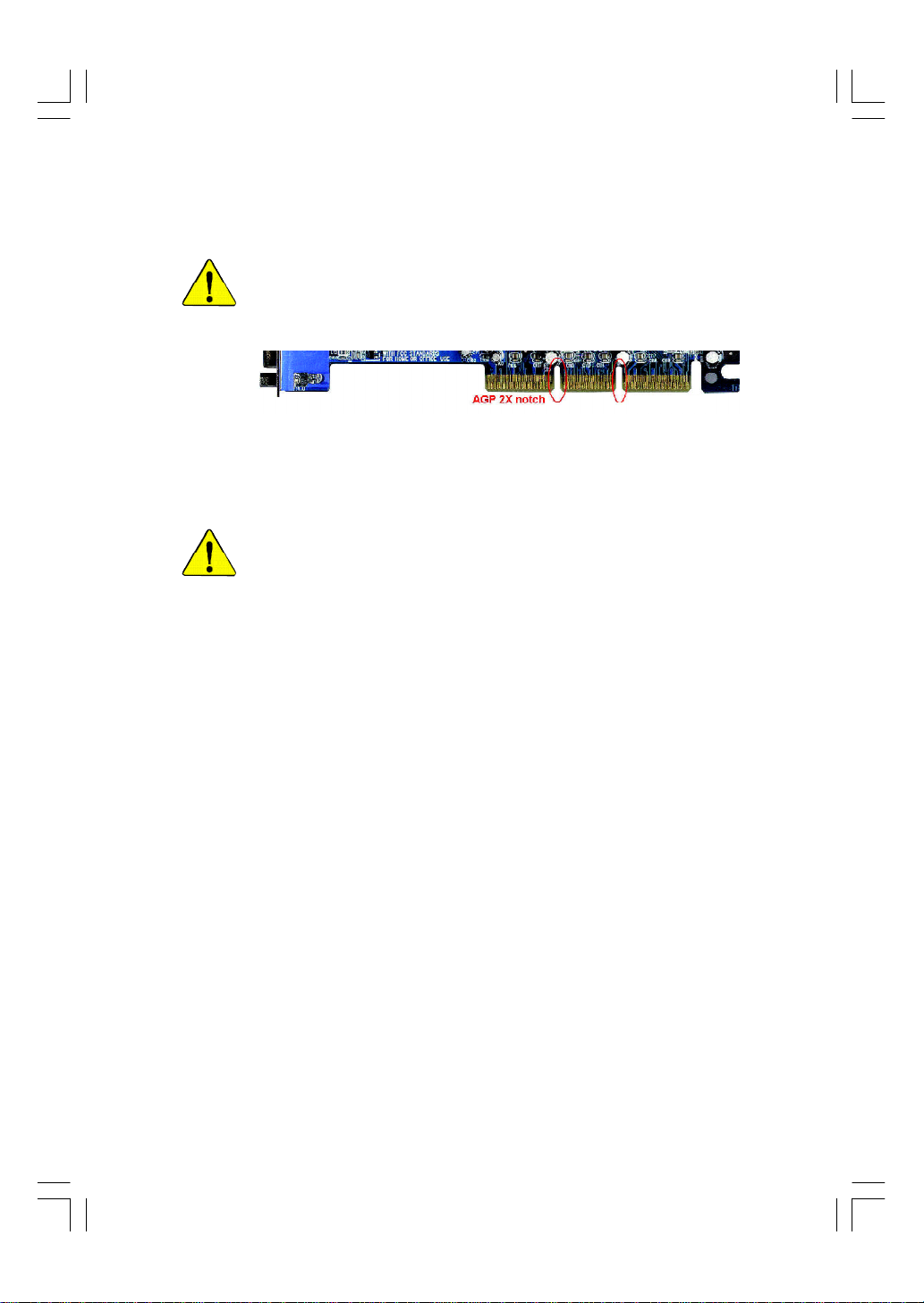
When you installing AGP card, please make sure the following notice
is fully understood and practiced. If your AGP card has "AGP 4X/8X
(1.5V) notch"(show below), please make sure your AGP card is AGP
4X/8X (1.5V).
AGP 4X/8X notch
Caution: AGP 2X card is not supported by Intel® 845(GE/PE) / 845(E/G)
/ 850(E) / E7205 / 865(G/PE/P) / 875P. You might experience system
unable to boot up normally. Please insert an AGP 4X/8X card.
Example 1: Diamond Vipper V770 golden finger is compatible with 2X/4X
mode AGP slot. It can be switched between AGP 2X(3.3V) or 4X/8X(1.5V)
mode by adjusting the jumper. The factory default for this card is 2X(3.3V).
The GA-8IP900MK (or any AGP 4X/8X only) motherboards might not
function properly, if you install this card without switching the jumper to 4X/8X
(1.5) mode in it.
Example 2: Some ATi Rage 128 Pro graphics cards made by "Power Color",
the graphics card manufacturer & some SiS 305 cards, their golden finger is
compatible with 2X(3.3V)/4X(1.5V) mode AGP slot, but they support 2X(3.3V)
only. The GA-8IP900MK (or any AGP 4X/8X only) motherboards might not
function properly, If you install this card in it.
Note : Although Gigabyte's AG32S(G) graphics card is based on ATi Rage
128 Pro chip, the design of AG32S(G) is compliance with AGP 4X(1.5V)
specification. Therefore, AG32S(G) will work fine with Intel® 845(GE/PE) /
845(E/G) / 850(E) / E7205 / 865(G/PE/P) / 875P based motherboards.
8ip900mk_1001_f.p65 2003/4/22, 下午 03:5193
Page 2
The author assumes no responsibility for any errors or
omissions that may appear in this document nor does the
author make a commitment to update the information
contained herein.
Third-party brands and names are the property of their
respective owners.
Please do not remove any labels on motherboard, this may
void the warranty of this motherboard.
Due to rapid change in technology, some of the
specifications might be out of date before publication of
this booklet.
8ip900mk_1001_f.p65 2003/4/22, 下午 03:5194
Page 3

Ausschla ger We g 41, 1F, 20537 Hamburg, Germany
( description of the apparatus, system, installation to which it refers)
(reference to the specification under which con formity is declared)
in accordance with 89/336 EEC-EMC Directive
o EN 55011 Limits and methods of measurement
o EN 55013
o EN 55014 Limits and methods of measurement
o EN 55015 Limits and methods of measurement
o EN 55020
T EN 55022 Limits and methods of measurement
o DIN VDE 0855
o part 10
o part 12
T CE marking
o EN 60065
o EN 60335
of radio disturbance characteristics of
industrial,scientific and medical (ISM
high frequency equipment
Limits and methods of measurement
of radio disturbance characteristics of
broadcast receivers and associated
equipment
of radio disturbance characteristics of
household electrical appliances,
portable tools and similar electrical
apparatus
of radio disturbance characteristics of
fluorescent lamps and luminaries
Immunity from radio interference of
broadcast receivers and associated
equipment
of radio disturbance characteristics of
information technology equipment
Cabled distribution systems; Equipment
for receiving and/or distribution from
sound and television signals
The manufacturer also declares the conformity of above mentioned product
Safety requirements for mains operated
electronic and related apparatus for
household and similar general use
Safety of household and similar
electrical appliances
(Stamp)
with the actual required safety standards in accordance with LVD 73/23 EEC
Declaration of Conformity
We, Manufacturer/Importer
(full address)
G.B.T. Te chnology Träding GMbH
declare that the product
Mother Board
GA-8IP900MK
is in conformity with
o EN 61000-3-2*
T EN 60555-2
o EN 61000-3-3* Disturbances in supply systems cause
T EN 60555-3
T EN 50081-1
T EN 50082-1
o EN 55081-2
o EN 55082-2
o ENV 55104
o EN50091-2
(EC conformity marking)
o EN 60950
o EN 50091-1
Manufacturer/Importer
Date : A pril 8, 2003
Disturbances in supply systems cause
by household appliances and similar
electrical equipment “Harmonics”
by household appliances and similar
electrical equipment “Voltage fluctuations”
Generic emission standard Part 1:
Residual commercial and light industry
Generic immunity standard Part 1:
Residual commercial and light industry
Generic emission standard Part 2:
Industrial environment
Generic emission standard Part 2:
Industrial environment
lmmunity requirements for household
appliances tools and similar apparatus
EMC requirements for uninterruptible
power systems (UPS)
Safety for information technology equipment
including electrical bussiness equipment
General and Safety requirements for
uninterruptible power systems (UPS)
Signature:
Name:
Timmy Huang
Timmy Huang
8ip900mk_1001_f.p65 2003/4/22, 下午 03:5295
Page 4
DECLARATION OF CONFORMITY
Per FCC Part 2 Section 2.1077(a)
Responsible Party Name:
Add ress:
Phone/Fax No:
hereby declares that the product
Product Name: Motherboard
Model Nu mber: GA-8IP900MK
Conforms to the following specifications:
FCC Part 15, Subpart B, Section 15.107(a) and Section 15.109(a),
Class B Digital Device
Supplementary Information:
This device complies with part 15 of the FCC Rules. Operation is
subject to the following two conditions: (1) This device may not
cause harmful and (2) this device must accept any inference received,
including that may cause undes ired operation.
Representative Person’s Name:
Signature:
G.B.T. INC. (U .S.A.)
17358 Railroad Street
City of Indu stry, CA 91748
(818) 854-9338/ (818) 854-9339
ERIC LU
Eric Lu
8ip900mk_1001_f.p65 2003/4/22, 下午 03:5296
Date:
April 8, 2003
Page 5

GA-8IP900MK
P4 Titan Series Motherboard
USER'S MANUAL
Pentium® 4 Processor Motherboard
Rev. 1001
12ME-8IP900MK-1001
Page 6

Table of Content
English
Ite m Checklist ..................................................................................4
Chapter 1 Introduction ......................................................................5
Chapter 2 Hardware Installation Process ......................................... 11
Chapter 3 BIOS Setup .................................................................... 33
Features Summary................................................................................................ 5
GA-8IP900MK Motherboard Layout ................................................................... 7
Block Diagram ....................................................................................................... 8
Step 1: Install the Central Processing Unit (CPU) .........................................12
Step 1-1: CPU Installation ............................................................................ 12
Step 1-2: CPU Cooling Fan Installation .......................................................... 13
Step 2: Install Memory Modules ....................................................................... 14
Step 3: Install expansion cards ......................................................................... 16
Step 4: Connect ribbon cables, cabinet wires and power supply .............. 17
Step 4-1: I/O Back Panel Introduction ............................................................ 17
Step 4-2: Connectors Introduction ................................................................. 19
The Main Menu (For example: BIOS Ver. : F2 )............................................ 34
Standard CMOS Features ................................................................................. 36
Advanc ed BIOS Features ................................................................................... 39
Integrated Peripherals ....................................................................................... 41
Power Management Setup ................................................................................ 46
PnP/PCI Configurations ...................................................................................... 49
PC Health Status .................................................................................................. 50
Frequency/Voltage Control ................................................................................ 52
Load Fail-Safe Defaults ...................................................................................... 54
- 2 -GA-8IP900MK Motherboard
Page 7

Load Optimized Defaults .................................................................................... 55
Set Supervisor/User Password .......................................................................... 56
Save & Exit Setup ................................................................................................. 57
Exit Without Saving ............................................................................................. 58
Chapter 4 Technical Reference .......................................................61
@BIOS™ Introduction ........................................................................................ 61
EasyTune™ 4 Introduction ................................................................................62
Flash BIOS Method Introduction ......................................................................63
Method 1 : Q-Flash .................................................................................... 63
Method 2 : @BIOS Utility ............................................................................ 65
2- / 4- / 6-Channel Audio Func tion Introuction ............................................... 67
Jack-Sensing Introuction ................................................................................... 73
Chapter 5 Appendix ....................................................................... 77
English
- 3 -
Table of Content
Page 8
Item Checklist
English
The GA-8IP900MK motherboard
CD for motherboard driver & utility
GA-8IP900MK user's manual
Quick PC Installation Guide
SATA RAID M anual
GC-SATA Card (optional)
(Manual; SATA cable x 1; Power cable x 1)
I/O Shield
IDE cable x 1 / Floppy cable x 1
Computer motherboards and expansion cards contain v ery delicate Integrated Circuit
(IC) chips. To protect them against damage from static electrici ty, you should follow
some precautions whenever you work on your computer.
1. Unplug your computer when working on the inside.
2. Use a grounded wrist strap before handling computer components. If you do not have one, touch
both of y our hands to a safely grounded object or to a metal object, such as the power supply
case.
3. Hold components by the edges and try not touch the IC chips, leads or connectors, or other
components.
4. Place components on a grounded antistatic pad or on the bag that came w ith the components
whenever the components are separated from the system.
5. Ensure that the ATX power supply is sw itched off before you plug in or remove the ATX power
connector on the motherboard.
Serial ATA cabl e x 2
2 Port USB Cable x 1
4 Port USB Cable x 1
SPDIF Kit x 1 (SPDIF Out Kit)
IEEE 1394 Cable x1
Audio Combo Kit x 1
(SURROUND-Kit + SPDIF Out Kit)
Motherboard Settings Label
Installing the motherboard to the chassis...
If the motherboard has mounting holes, but they don't line up with the holes on the base and there are
no slots to attac h the spacers, do not become alarm ed you can still attach the spacers to the mounting
holes. Just cut the bottom portion of the spacers (the spacer may be a little hard to cut off, so be careful of
your hands). In this way y ou can still attach the motherboard to the base without worrying about short
circuits. Sometimes y ou may need to use the plastic springs to isolate the screw from the motherboard
PCB surface, because the circuit wire may be near by the hole. Be careful, don't let the screw contact
any printed circuit write or parts on the PCB that are near the fix ing hole, otherwise it may damage the
board or cause board malfunctioning.
- 4 -GA-8IP900MK Motherboard
Page 9

Chapter 1 Introduction
Features Summary
Form Factor — 24.4cm x 24.4c m M icro ATX size form factor, 4 layers PCB
CPU — Socket 478 for Intel® Micro FC-PGA2 Pentium® 4 processor
— Support Intel® Pentium® 4 (Northwood, Prescott) processor
— Support Intel® Pentium® 4 Processor with HT Technology *
— Intel® Pentium® 4 533/400MHz FSB
— 2nd cache depends on C PU
Chipset — Intel® Chipset 865P HOST/AGP/Controller
— Intel® ICH5 I/O C ontroller Hub
Memory — 4 184-pin DDR DIM M sockets
— Supports Dual C hannel DDR 333/DDR266 DIMM
— Supports 128MB/25 6MB/512MB/1G B unbuffere d DRAM
— Supports up to 4GB DRAM (M ax)
— Supports only DD R DIM M
I/O Control — ITE8 712F
Slots — 3 PCI slot supports 33MH z & PC I 2.3 compliant
On-Board IDE — 2 IDE controllers prov ide s IDE HDD /C D-ROM (I DE1, IDE2) with
PIO, Bus Master (U ltra DMA33/ATA66/ATA100) operation modes
— Can co nnect up to 4 IDE devices
Serial ATA — 2 Serial ATA connectors in 150 M B/s operation mode
— Controlled by ICH 5
On-Board Peripherals — 1 Floppy port supports 2 FDD w ith 360K, 720K,1.2M , 1.44M
and 2.88M bytes
— 1 Parallel port supports No rmal/EPP/ECP mode
— 2 Serial ports (COM A & C OM B)
— 8 USB 2.0/1.1 p orts (4 x Rear, 4 x Front by c able)
— 1 IrDA connector for IR/C IR
— 1 Front Audio con nector
Hardware Monitor — CPU /Sy stem fan rev olution detect
— CPU temperature detect
— CPU w a rning tempe rature
— System v oltage detect
— CPU /Sy s tem fan fail w arning
On-Board LAN — Builit i n Intel® 82562 Chipset
Data transfer rate 10/100 sup ported
— 1 RJ45 port
English
- 5 -
to be continued......
Introduction
Page 10

On-Board Sound — Realtek ALC 655 codec
English
PS/2 Connector — PS/2 Key board interface and PS/2 M ouse interace
BIOS — Licensed Phoenix BI OS, 2M bit FWH
Additional Features — PS/2 Key board pow er on by password
— Supports Jack Sensing function
— Line Out / 2 front speaker
— Line In / 2 rea r speaker (by s/w sw itch)
— Mic In / center & subwoofer (by s/w s w itch)
— CD In / AUX In / Game port
— PS/2 M ouse pow er on
— STR ( Suspend-To -RAM)
— AC Rec ov ery
— Poly fuse for key board ov er-c urrent protection
— USB K B/M ouse wake up from S3
— Supports @BIOS
— Supports EasyTune 4
— Supports clear passw ord function
"*" HT functionality requirement content :
Enabling the functionality of Hy per-Threading Technology for y our computer system requires all
of the following platform components:
- CPU: An Intel® Pentium 4 Processor with HT Technology
- Chipset: An Intel® Chipset that supports HT Technology
- BIOS: A BIOS that supports HT Technology and has it enabled
- OS: An operation system that has optimizations for HT Technology
Please set the CPU host frequency in accordance w ith your processor's specifications.
We don't recommend you to set the sy stem bus frequency over the CPU's specification because
these specific bus frequencies are not the standard specifications for CPU, chipset and most of the
peripherals. Whether y our system can run under these specific bus frequencies properly will
depend on your hardware configurations, including CPU, Chipsets, SDRAM, Cards… etc.
- 6 -GA-8IP900MK Motherboard
Page 11
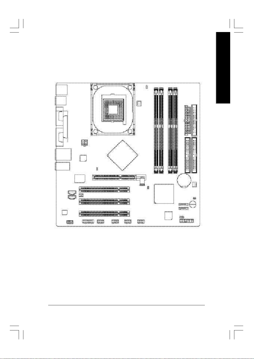
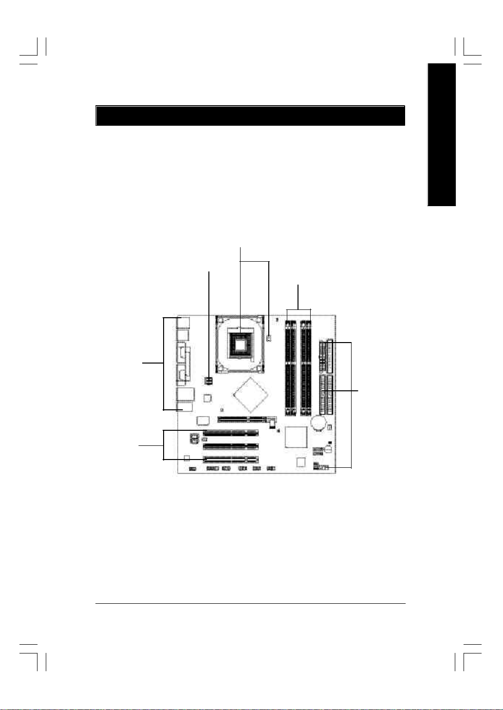
GA-8IP900MK Motherboard Layout
English
KB_MS
R_USB
USB
AUDIO1
CD_IN
AUX_IN
CODEC
COMA
COMB
LPT
LAN
F_AUDIO
ATX_12V
Intel
82562EZ
2X_DET
ITE
8712F
AGP
SUR_CEN
GAME INFO_LINK
IR_CIR
SOCKET 478
Intel 865P
PCI1
PCI2
PCI3
F_USB1
DIMM_LED
CPU_FAN
CLR_PWD
F_USB2
GA-8IP900MK
DDR1
DDR2
DDR3
Intel ICH5
BIOS
DDR4
BAT
SATA1
SATA0
ATX
IDE2
SYS _FAN
CI
PWR_LED
F_PANEL
FDD
IDE1
Buzzer
- 7 -
Introduction
Page 12
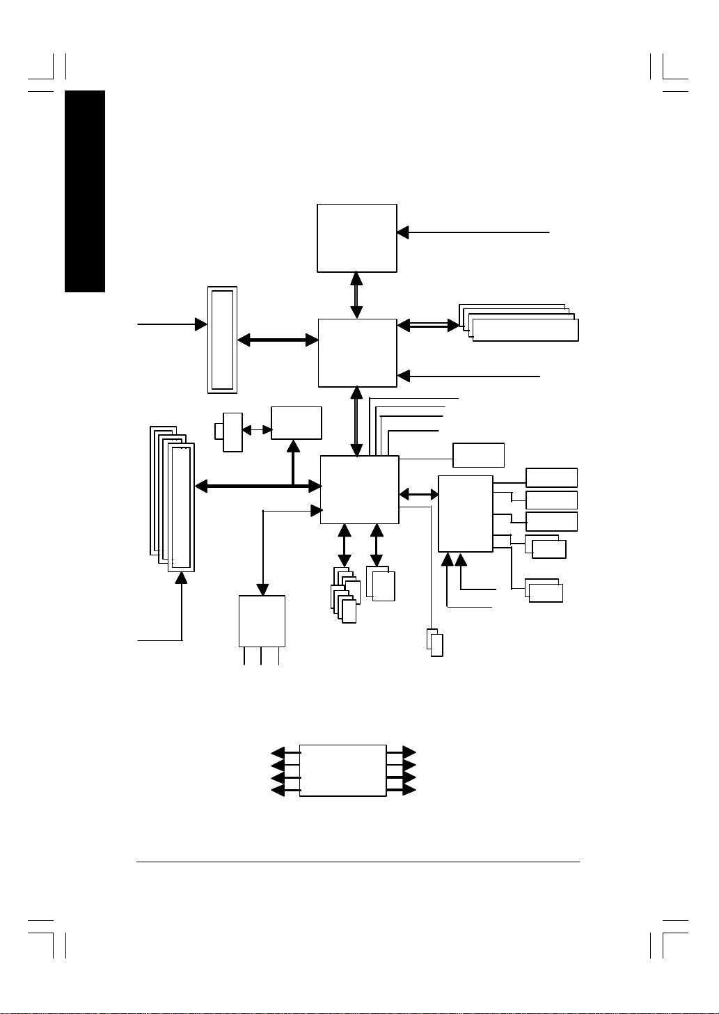
Block Diagram
English
PCICLK
(33MHz)
AGPCLK
(66MHz)
3 PCI
AGP 4X/8X
RJ45
AC97
CODEC
MIC
LINE-IN
Intel
82562EZ
AC97 Link
LINE-OUT
Pentium 4
Socket 478
CPU
System Bus
533/400MHz
Intel 865P
Intel
ICH5
ATA33/66/100
IDE Channels
8 USB
Ports
CPUCLK+/- (100/133 MHz)
266/333MHz
MCHCLK (100/133 MHz)
66 MHz
33 MHz
48 MHz
LPC BUS
14.318 MHz
BIOS
IT8712F
24 MHz
33 MHz
2 Serial ATA
DDR RAM
Game Port
Floppy
LPT Port
PS/2 KB/Mouse
2 COM Ports
PCICLK (33MHz)
USBCLK (48MHz)
14.318 MHz
33 MHz
CLK GEN
- 8 -GA-8IP900MK Motherboard
CPUCLK+/- (100/133MHz)
AGPCLK (66MHz)
MCHCLK (100/133MHz)
ICH3V66 (66MHz)
Page 13

English
- 9 -
Introduction
Page 14

English
- 10 -GA-8IP900MK Motherboard
Page 15
Chapter 2 Hardware Installation Process
To set up y our computer, you must complete the following steps:
Step 1- Install the Central Processing Unit (CPU)
Step 2- Install memory modules
Step 3- Install ex pansion cards
Step 4- Connect ribbon cables, cabinet wires, and power supply
Step 1
Step 4
Step 2
Step 4
English
Step 4
Step 3
Congratulations! You hav e accomplished the hardware installation!
Turn on the power supply or connect the power cable to the power outlet. Continue with the
BIOS/software instal lation.
- 11 - Hardware Installation Process
Page 16
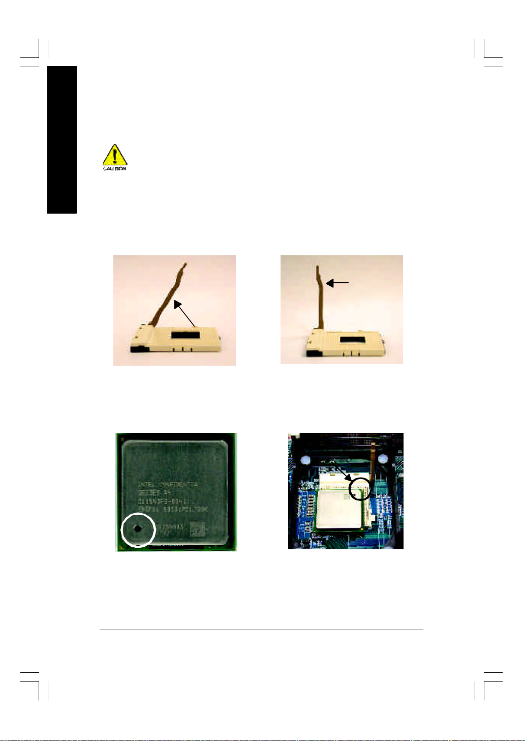
Step 1: Install the Central Processing Unit (CPU)
English
Step 1-1: CPU Installation
Before installing the processor, adhere to the following warning:
1. Please make sure the CPU type is supported by the motherboard.
2. If you do not match the CPU socket Pin 1 and CPU cut edge well, it will
cause improper installation. Please change the insert orientation.
Angling the
rod to 65
1. Angling the rod to 65-degree maybe
feel a kind of tight , and then continue
pull the rod to 90-degree when a noise
"cough" made.
0
Pin1 indicator
3. CPU Top View
Socket
Actuation
Lever
2. Pull the rod to the 90-degree directly.
Pin1 indicator
4. Locate Pin 1 in the socket and
look for a (golden) cut edge on the
CPU upper co rner. Then insert
the CPU into the socket.
- 12 -GA-8IP900MK Motherboard
Page 17
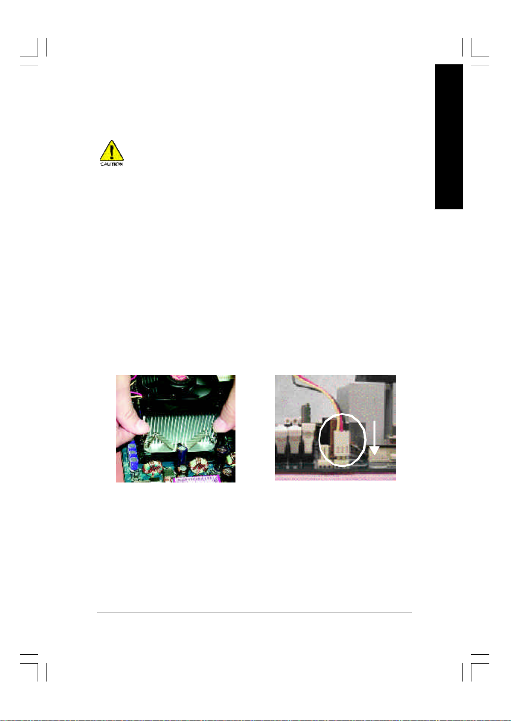
Step 1-2: CPU Cooling Fan Installation
Before installing the CPU cooling fan, adhere to the following warning:
1. Please use Intel approved cooling fan.
2. We recommend you to apply the thermal tape to provide better heat
conduction between your CPU and cooling fan.
(The CPU cooling fan might stick to the CPU due to the hardening of
the thermal paste. During this condition if you try to remove the cool-
ing fan, you might pull the processor out of the CPU socket alone with
the cooling fan, and might damage the processor. To avoid this from
happening, we suggest you to either use th erm al tape instead of
thermal paste, or remove the cooling fan with extreme caution.)
3. Make sure the CPU fan powe r cab le is pl ugg ed in to the CPU fan
connector, this completes the installation.
Please refer to CPU cooling fan u s er 's man ua l for more detail
installation procedure.
English
1. Fasten the cooling fan supporting-
base onto the CPU soc ket on the
motherboard.
2. Make sure the CPU fan is plugged
to the CPU fan connector, tha n
install complete.
- 13 - Hardware Installation Process
Page 18
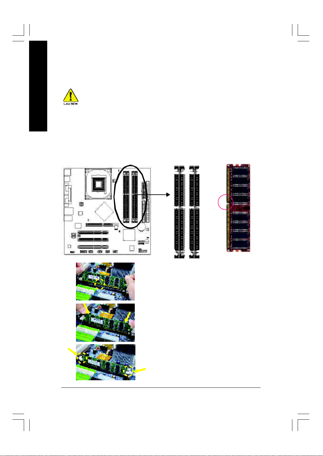
Step 2: Install Memory Modules
English
The motherboard has 4 dual inline memory module (DIMM) socke ts. The BIOS will automatically
detects memory type and size. To install the memory module, just push it vertically into the DIMM
socket. The DIMM module can only fit in on e direction due to the notch. Memory siz e ca n vary
between sockets.
Before installing the memory modules, adhere to the following warning:
1. When DIMM LED is ON, do not install / remove DIMM from socket.
2. Please note that the DIMM module can only fit in one direction due to
the one notch. Wrong orientation will caus e im proper installation.
Please change the insert orientation.
Notch
DDR
1. The DIMM socket has a notch, so the DIMM memory
module can only fit in one direction.
2. Insert the DIM M memory module vertically into the DIMM
socket. Then push it down.
3. Close the plastic clip at both ed ges of the DIMM sockets
to lock the DIMM mod ule.
Reverse the installation steps when y ou wish to remove
the DIMM mod ule.
- 14 -GA-8IP900MK Motherboard
Page 19

DDR Introduction
Established on the existing SDRAM industry infrastructure , DDR (Double Data Rate) memory is a
high performance and cost-effective solution that allows easy adoption for memory ve ndors, OEMs
and sy stem integrators.
DDR memory is a sensible ev olutionary solution for the PC industry that builds on the ex isting
SDRAM infrastruc ture, y et makes aw esome advances in solving the system performance bottleneck
by doubling the memory bandwidth. DDR SDR AM will offer a superior solution and migration path from
existing SDRAM designs due to its availability, pri cing and ov e rall mar ket supp ort. PC2100 DDR
memory (DDR266) doubles the data rate through readi ng and w riting at both the rising and falling edge
of the clock, achieving data bandwidth 2X greater than PC133 w hen running w ith the same DRAM
clock frequency . With peak bandwidth of 2.664GB per second, DDR memory enables system OEMs
to build high performance and low latency DRAM subsy stems that are suitable for servers, w orkstations,
high-end PC's and value desktop SMA systems.
Dual Channel DDR:
GA-8IP900MK supports Dual Channel Technology.
When Du al Channel Technology is activated, the bandwidth of memory bus w ill be double the original
one,w ith the fastest sp eed at 5 .3GB/s DDR333.
GA-8IP900MK includes four DIMM slots, and each Channel has 2 DIMMs as following:
Channel A : DIMM 1, 2
Channel B : DIMM 3, 4
Below are the explanations:
If y ou want to opera te the Dual Channel Technology, please note the following explanations
due to the limitation o f Intel chipset specifications.
1. Only one DDR memory module i s i nstall ed: Th e Dual Ch ann el Technology can 't
operate when only one DDR memory module is installed. Additiona lly, you can boot the
system only when the memory module is inserted into Channel A. On the other hand,
the memory module must be inserted into DIMM1 or DIMM3 sockets.
2. Two DDR memory modules are installed (the same memory size and type): The Dual
Channel Technology will operate when two memory modules are inserted individually
into Channel A and B. If y ou install two me mory modules in the same channel, the Dual
Channel Technology will not operate. Additionally, y ou can boot the sy stem only w hen
one of the memory modules is in serted into Channel A. On the other hand, the memory
module must be inserted into DIMM1 or DIMM3 soc kets.
3. Three DDR memory modules are installed: Please note that the Dual Channel Technology will "not" operate when three DDR memory modules are in stalled. If you install
three memory modules, the system will only detect those memory modules inserted in
Channel A, and those in Channel B will not be detected!
English
- 15 - Hardware Installation Process
Page 20
4. Four DDR memory modules are installed: If you install four memory modules at the same time, the
Dual Channel Technology will operate only when those modules have the same memory size and
type.
English
The following tables include all memory-installed combination types:
(Please note that those ty pes not in the tables w ill not boot up.)
l Figure 1: Dual Channel Technology (DS: Double Side, SS: Single Side)
2 memory modules
4 memory modules
l Figure 2: Don't operate Dual Channel Technology (DS: Double Side, SS: Single Side)
1 memory mo dule
2 memory mod ules
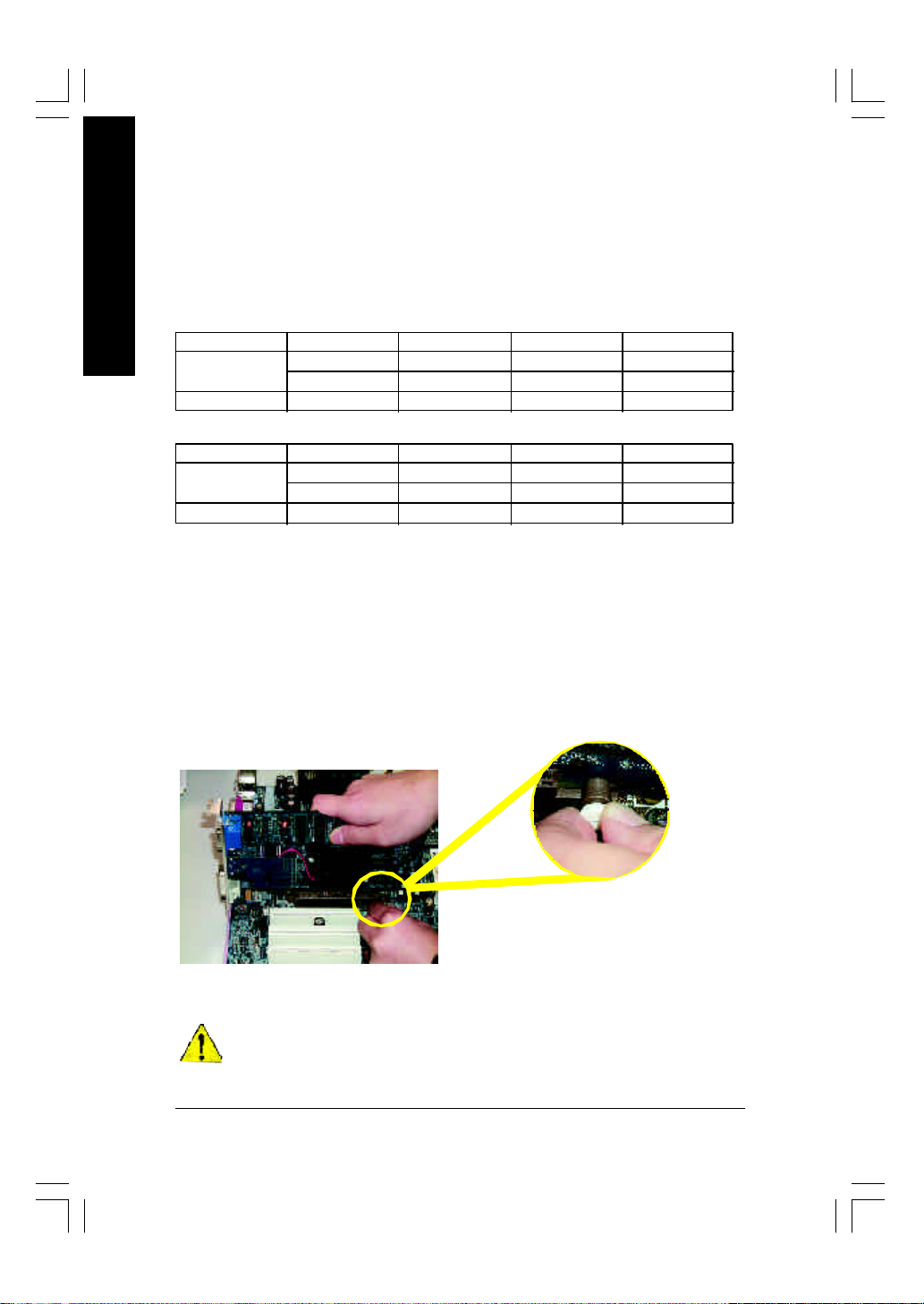
Step 3: Install expansion cards
1. Read the related expansion card's instruction document before install the expansion c ard into the
2. Remove your computer's chassis cover, screws and slot bracket from the computer.
3. Press the expansion card firmly into expansion slot in motherboard.
4. Be sure the metal contacts on the card are indeed seated in the slot.
5. Replace the screw to secure the slot bracket of the ex pansion card.
6. Replace your computer's chassis cover.
7. Power on the computer, if necessary , setup BIOS utility of expansion card from BIOS.
8. Install related driv er from the operating sy stem.
DIMM 1 DIMM 2 DIMM 3 DIMM 4
DS/SS X DS/SS X
X DS/SS X DS/SS
DS/SS DS/SS DS/SS DS/SS
DIMM 1 DIMM 2 DIMM 3 DIMM 4
DS/SS X X X
X X DS/SS X
DS/SS DS/SS X X
computer.
Please carefully pull out the sm all w hite-d rawable
bar at the end of the AGP slot when y o u try to
install/ Uninstall the AGP card. Please ali gn the
AGP card to the onboard A GP slot and press firmly
AGP Card
When an AGP 2X (3.3V) card is installed the 2X_DET w ill light up, ind icating a non-supported
graphics card is inserted. Informing users that system might not boot up normally due to
AGP 2X (3.3V) is not supported by the chipset.
down on the slot .Make sure y ou r AG P c ard is
locked by the small white- drawable bar.
- 16 -GA-8IP900MK Motherboard
Page 21
Step 4: Connect ribbon cables, cabinet wires and
power supply
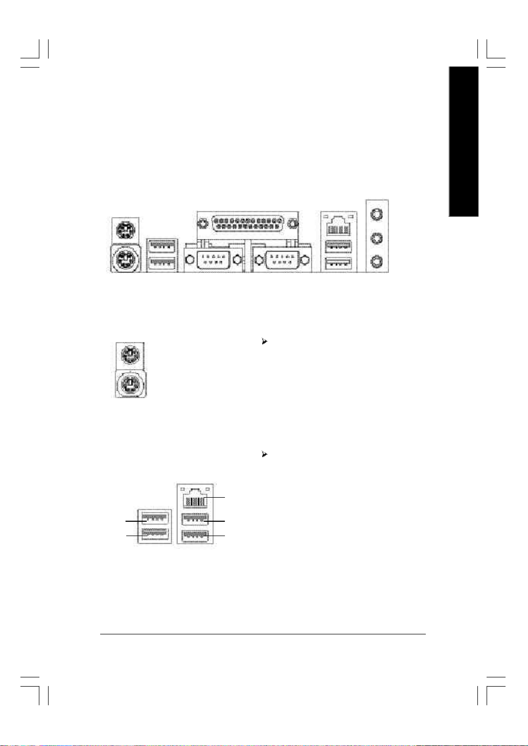
Step 4-1: I/O Back Panel Introduction
u
w
v
u PS/2 Keyboard and PS/2 Mouse Connector
x
English
y
PS/2 Mouse Connector
(6 pin Female)
PS/2 Keyboard Connector
(6 pin Female)
v/x USB/LAN Connector
USB 0
USB 1
LAN
USB 2
USB 3
This connector su pports standard PS/2
keyboard and PS/2 mouse.
Before you connect your device(s ) in to U SB
connector(s), please make sure your dev ice(s)
such as U SB key board, mouse , scanner, zip,
speaker...etc. Have a standard USB interface.
Also make sure y our OS supports U SB controller.
If your OS does not support U SB controller, please
contact OS v endor for possible patch or driver
upgrade. For more information please contact y our
OS or device(s) vendors.
- 17 - Hardware Installation Process
Page 22
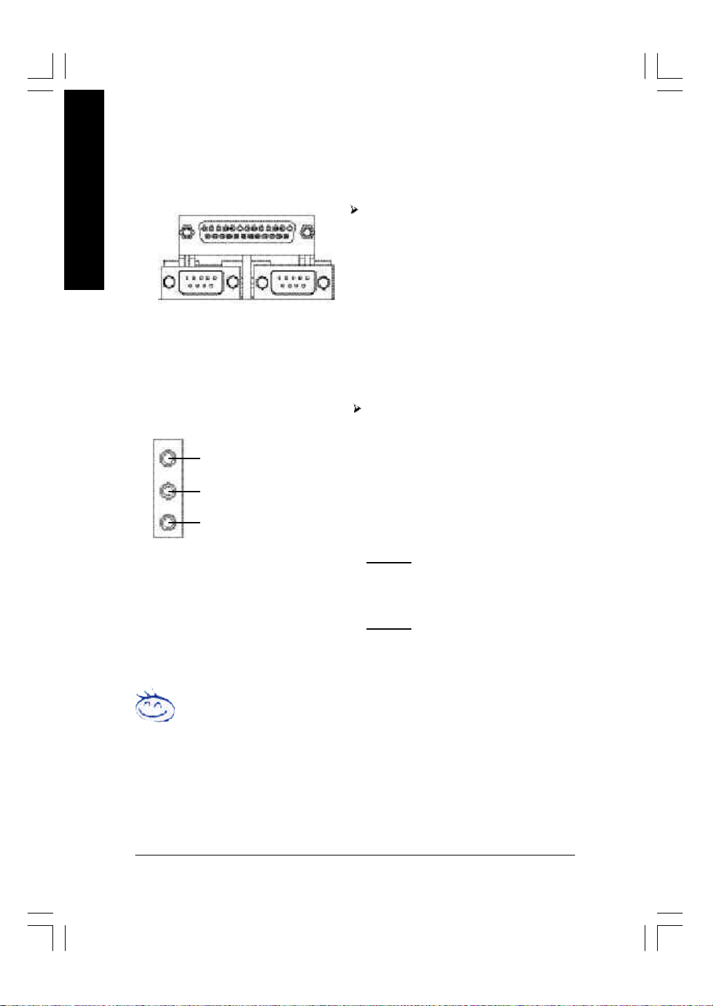
w Parallel Port and Serial Ports (COMA/COMB)
English
Parallel Port
(25 pin Female)
This connector supports 2 standard C OM ports
and 1 Parallel port. Device like printer can be
connected to Parallel port ; mouse and modem
etc can be connected to Serial ports.
COMA
Serial Port (9 pin Male)
y Audio Connectors
Line In (Rear Speaker)
Line Out (Front Speaker)
MIC In (Center and Subwoofer)
If you want the detail information for 2-/4-/6-channel audio setup
installation, please refer to page 67.
COMB
After install onboard audio driv er, y ou m ay
connect speaker to Line Out jack, microphone to
MIC In jack. Device like CD-ROM,w alkman etc.
can be connected to Line-In jack.
Please note:
You are a ble to use 2-/4-/6-channel audio feature
by S/W selection.
If you want to enable 6-channel function, y ou
have 2 choose for hardware connection.
Method1:
Connect "Front Speaker" to "Line Out"
Connect "Rear Speaker" to "Line In"
Connect "Center and Subwoofer" to "M IC Out " .
Method2:
You can refer to page 28, a nd contact y our
nearest dealer for optional SUR_CEN cable.
- 18 -GA-8IP900MK Motherboard
Page 23
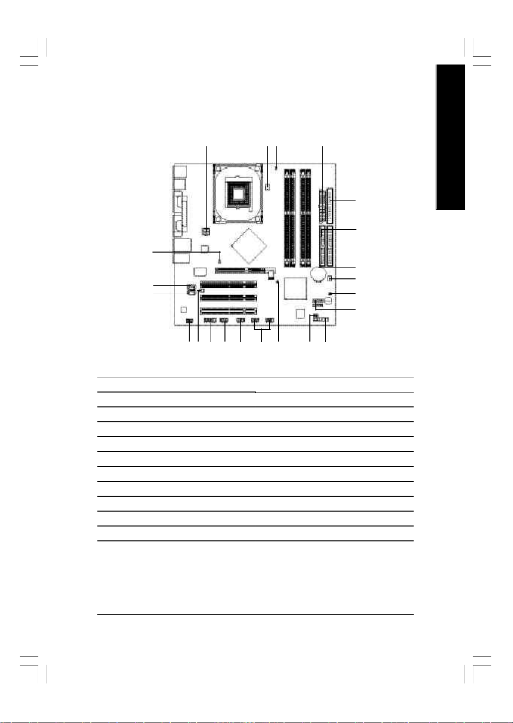
Step 4-2: Connectors Introduction
English
12
15
1) ATX_12V
2) ATX
3) CPU_FAN
4) SYS_FAN
5) FDD
6) IDE1 / IDE2
7) SATA0 / S ATA1
8) BAT
9) F_PANEL
10) PWR_LED
11) DIMM_LED
1 3
181120 22
19
17
2
9
10131416
12) 2X_DET
13) F_AUDIO
14) CD_IN
15) AUX_IN
16) SUR_CEN
17) F_USB1 / F_USB2
18) IR_CIR
19) GAME
20) INFO_LINK
21) CI
22) CLR_PWD
5
6
8
4
21
7
- 19 - Hardware Installation Process
Page 24
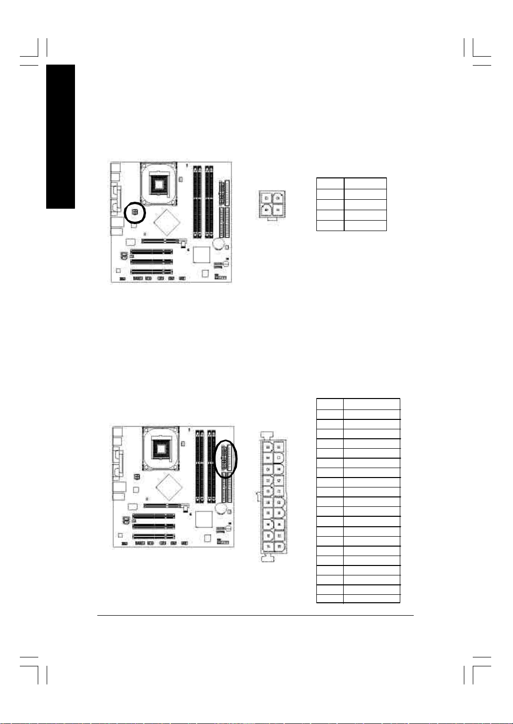
1) ATX_12V (+12V Power Co nnector)
English
2) ATX (ATX Power)
This connector (ATX_12V) supplies the CPU operation v oltage (Vcore).
If this "ATX_12V connec tor" is no t connected, sy stem cannot boot.
Pin No. Definition
2
4
1
3
1 GND
2 GND
3 +12V
4 +12V
AC power cord should only be connected to your pow er sup ply unit after ATX pow er cable and
other related devices are firmly connected to the mainboard.
Pin No. Definition
1 3.3V
2 3.3V
3 GND
11
20
1
10
4 VCC
5 GND
6 VCC
7 GND
8 Pow er Good
9 5V SB (stand by +5V)
10 +12V
11 3.3V
12 -12V
13 GND
14 PS_ON (soft on/off)
15 GND
16 GND
17 GND
18 -5V
19 VCC
20 VCC
- 20 -GA-8IP900MK Motherboard
Page 25
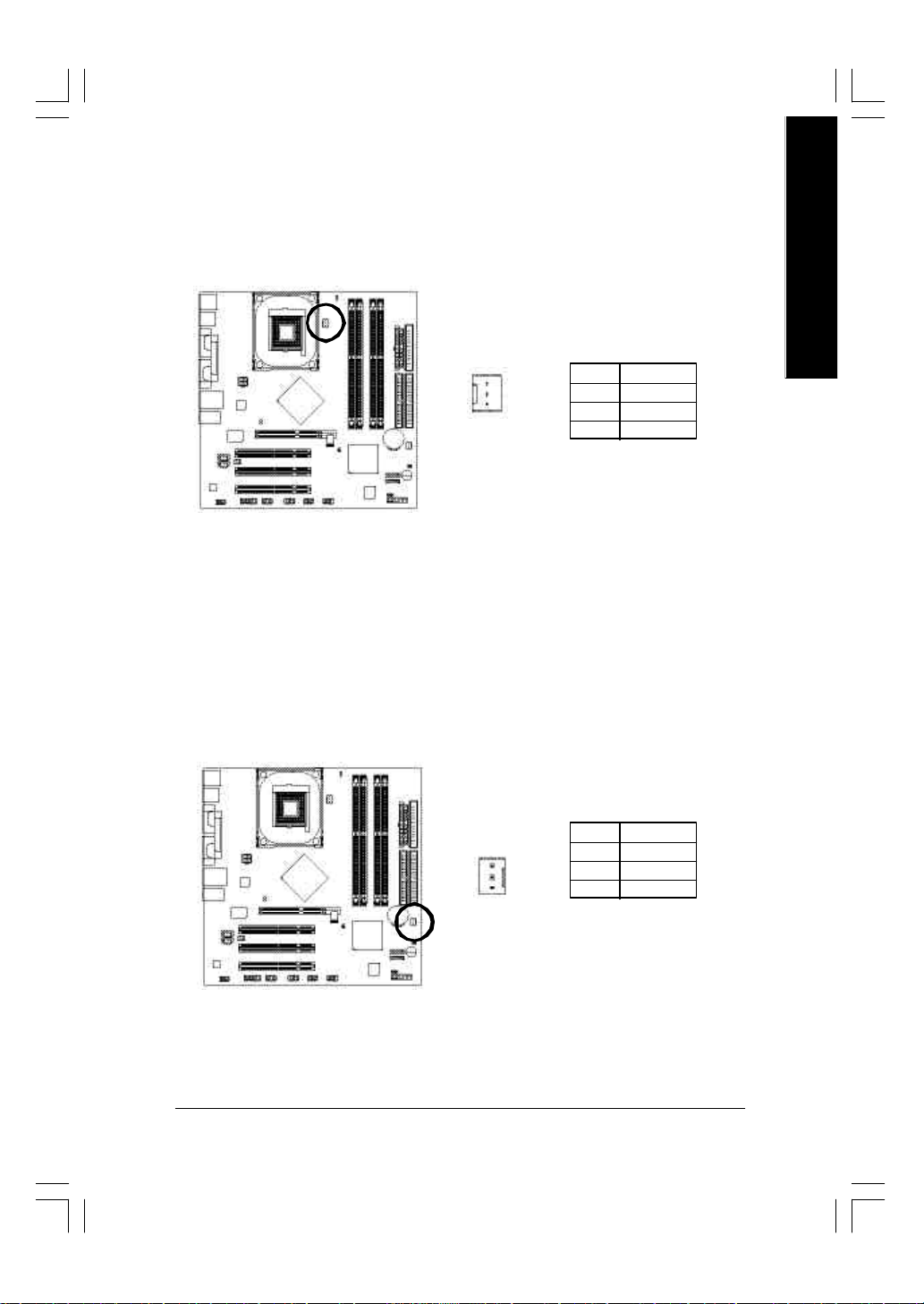
3) CPU_FAN (CPU Fan Connector)
Please note, a proper installation of the CPU cooler is essential to prevent the CPU from running
under abnormal condition or damaged by overheating. The CPU fan conne ctor suppo rts Max .
current up to 600 mA.
English
1
Pin No. Definition
1 GND
2 +12V
3 Sense
4) SYS_FAN (System Fan Connector)
This connector allows you to link with the cooling fan on the sy s tem case to low er the sy stem
temperature.
Pin No. Definition
1 GND
2 +12V
3 Sense
1
- 21 - Hardware Installation Process
Page 26
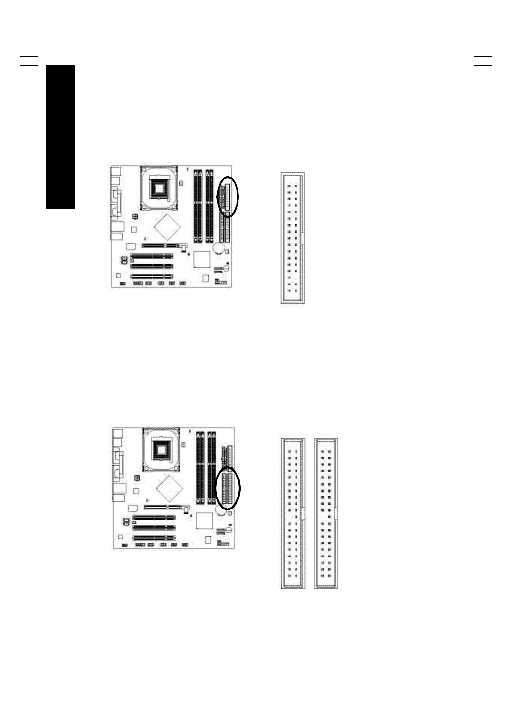
5) FDD (Floppy Connector)
English
Please connect the floppy drive ribbon cables to FDD. It supports 360K, 1.2M, 720K, 1.44M and
2.88M bytes floppy disk types.
The red stripe of the ribbon cable must be the same side with the Pin1.
34
2
6) IDE1 / IDE2 (IDE1 / IDE2 Connector)
Important Notice:
Please connect first hard disk to IDE1 and connect C D-ROM to IDE2.
The red stripe of the ribbon cable must be the same side with the Pin1.
33
1
3940
12
IDE2
- 22 -GA-8IP900MK Motherboard
IDE1
Page 27
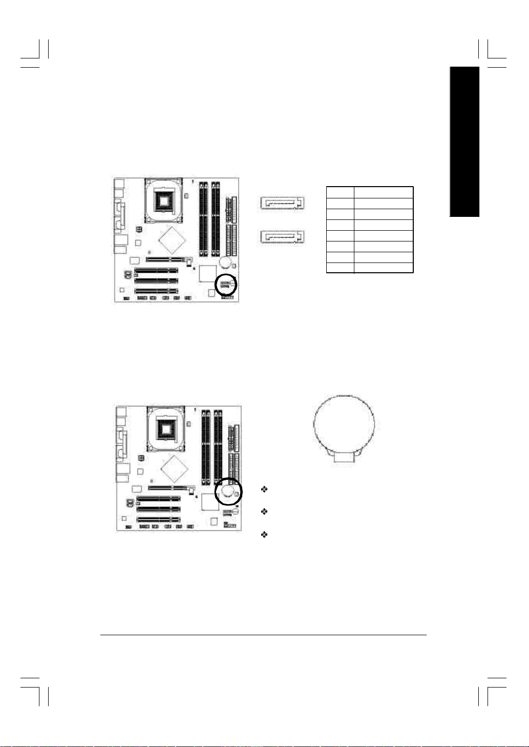
7) SATA0 / S ATA1 (S erial ATA Connector)
You can connect the Serial ATA dev i ce to this connector, it provides you high speed transfer rates
(150MB/sec).
Pin No. Definition
7
1
SATA1
17
SATA0
1 GND
2 TXP
3 TXN
4 GND
5 RXN
6 RXP
7 GND
8) BAT (BATTERY)
English
+
CAUTI ON
Danger of ex plosion if battery is inco rre ctly
replaced.
Replace only w ith the same or equivalent type
recommended by the manufacturer.
Dispose of used batteries acc or di ng to th e
manufacturer's instructions.
If y ou want to erase CMOS...
1. Turn OFF the computer and unplug the power cord.
2. Remove the battery , wait for 30 second.
3. Re-install the battery.
4. Plug the pow er cord and turn ON the computer.
- 23 - Hardware Installation Process
Page 28
9) F_PANEL (2 x 10 pins Connector)
Please connect the power LED, PC speaker, reset sw itch and pow er sw itch etc of your chassisfront
panel to the F_PANEL connector according to the pin assignment above.
English
Messag e LED/
Pow er/
Sleep LED
2
1 1
1 1
1
IDE Hard Dis k Active LED
Soft Power
Conne ctor
MSG+
MSG-
HD-
HD+
Reset Switch
PW+
RES-
PW-
RES+
NC
Speak er Connector
SPEAK+
SPEAK-
1
20
19
HD (IDE Hard Disk Active LED) Pin 1: LED anode(+)
(Blue) Pin 2: LED cathode(-)
SPK (Speaker Connector) Pin 1: VCC(+)
(Amber) Pin 2- Pin 3: NC
Pin 4: Data(-)
RES (Reset Sw itch) Open: Normal Operation
(Green) Close: Reset H ardware Sy stem
PW (Soft Power Connector) Open: Normal Operation
(Red) Close: Power On/Off
MSG(Message LED/ Power/ Sleep LED) Pin 1: LED anode(+)
(Yellow) Pin 2: LED cathode(-)
NC (Purple) NC
- 24 -GA-8IP900MK Motherboard
Page 29
10) PWR_LED
PWR_LED is connect with the sy stem power indicator to indicate whether the system is on/off.
It w ill blink when the sy stem enters suspend mode. If you use dual color LED, pow er L ED will turn
to another color.
English
1
Pin No. Definition
1 MPD+
2 MPD-
3 MPD-
11) DI MM_LED
Do not remov e memory modules while DIMM_LED is on. It might cause short or othe r unexpected
damages due to the stand by voltage. Remove memory modules only w hen AC power cord is
disconnected.
_
+
- 25 - Hardware Installation Process
Page 30

12) 2X_DET
English
13) F_AUDIO (Front Audio Connector)
When an AGP 2X (3.3V) card is installed the 2X _DET w ill lig ht up, in dica ting a no n-supported
graphics card is inserted. Informing users that system might not boot u p normall y due to AGP 2X
(3.3V) is not supported by the chipset.
_
+
If y ou want to use Front Audio connector, you must remove 5-6, 9-10 Jumper.
In order to utili ze the front audio header, your chassis must have front audio connector. Also please
make sure the pin assigment on the cabl e is the same as the pin assigment on the MB header. To
find out if the cha ssis yo u are bu y ing su pport fr ont audio conn ector, please c ontact y our dea ler.
Please note, y ou can hav e the alternative of using front audio connector or of using rear audio
connector to play sound.
Pin No. Definition
1 MIC
2 GND
10
2
9
1
3 REF
4 Pow er
5 Fron t Audio (R)
6 Rear Audio (R)
7 Rese rved
8 No Pin
9 Fron t Audio (L)
10 Rear Audio (L)
- 26 -GA-8IP900MK Motherboard
Page 31

14) CD_IN (CD I n Connector)
Connect CD-ROM or DVD- ROM audio out to the conne ctor.
1
15) AUX_IN (AUX In Conn ector)
Connect other device (such as PCI TV Tunner audio out) to the connector.
English
Pin No. Definition
1 CD-L
2 GND
3 GND
4 CD-R
Pin No. Definition
1
1 AUX-L
2 GND
3 GND
4 AUX-R
- 27 - Hardware Installation Process
Page 32

16) SUR_CEN ( S urround Center C onnector)
English
Please contact your nearest dealer for optional SUR_CEN cable.
652
1
Pin No. Definition
1 SUR OUTL
2 SUR OUTR
3 GND
4 No Pin
5 CENTE R_OUT
6 BASS _OUT
17) F_USB1 / F_US B2 ( Front US B C onnector, Yellow)
Be careful with the polarity of the front USB con nector. Che ck the pin ass ignm ent w hi le you
connect the fr ont USB ca ble. Plea se contact your ne arest dealer for optional fr ont USB cable.
F_USB1
2 10
F_USB2
1 9
Pin No. Definition
1 Pow er
2 Pow er
3 USB Dx-
4 USB Dy-
5 USB Dx+
6 USB Dy+
7 GND
8 GND
9 No Pin
10 NC
2 10
1 9
- 28 -GA-8IP900MK Motherboard
Page 33

18) IR_CI R
Make sure the pin 1 on the IR device is aling w ith pin one the connector. To enable the IR/CIR
function o n the board, you are required to purchase an option IR/CIR module. For detail information
please contact your autherized Gigabyte distributor. To use IR function only, please connect IR
module to Pin1 to Pin5.
Pin No. Definition
1 VCC
2 NC
6 10
1 5
3 IRRX
4 GND
5 IRTX
6 NC
7 CIRRX
8 +5VSB
9 CIRTX
10 NC
19) GAME (Game Connector)
This connector supports joystick, MIDI keyboard and other relate audio dev ices.
English
Pin No. Definition
1 VCC
2 GRX 1_R
3 GND
2
1
16
15
4 GPSA2
5 VCC
6 GPX 2_R
7 GPY 2_R
8 MSI_R
9 GPSA1
10 GND
11 GPY1_R
12 VCC
13 GPSB1
14 MSO_R
15 GPSB2
16 No Pin
- 29 - Hardware Installation Process
Page 34

20) INFO_ LI NK
English
21) CI (CAS E OPEN)
This connector allows y ou to connect some external devices to provide y ou e x tra func tion.
Pin No. Definition
1 SMB CLK
2 VCC
102
1
9
3 SMBD ATA
4 GPIO
5 GND
6 GND
7 No Pin
8 NC
9 +12V
10 +12V
This 2-pin connector allows your system to enable or disable the "Case Open" item in BIOS , if the
system case begin remove.
1
Pin No. Definition
1 Sig nal
2 GND
- 30 -GA-8IP900MK Motherboard
Page 35

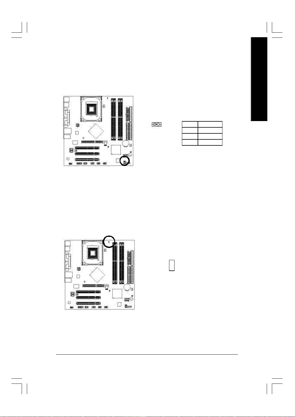
22) CLR_PWD
When Jumper is set to "open" and system is restarted, the password that is set w ill be cleared.
On the contrary when Jumper is set to "close", the current status remains.
Open: Clear Password
1
Close: Normal
1
English
- 31 - Hardware Installation Process
Page 36

English
- 32 -GA-8IP900MK Motherboard
Page 37

Chapter 3 BIOS Setup
BIOS Setup is an overview of the BIOS Setup Program. The program that allows users to modify the
basic system configuratio n. This type of information is stored in battery-backed CM OS RAM so that it
retains the Setup information when the power is turned off.
English
ENTERING
Powering ON the computer and pressing <Del> immediately w ill allow you to enter Setup. If you require
more advanced BIOS settings, please go to " Advanced BIOS" setting menu. To enter Advanced BIOS
setting menu, press " Ctrl+F1" key on the BIOS screen.
CONTROL
<á> Move to previous item
<â> Move to next item
<ß> M ove to the item in the left hand
<à> M ove to the item in the right hand
Enter Select item
<Esc> Main Menu - Quit and not save changes into CMOS Status Page Setup Menu and
<+/PgUp> Increase the numeric value or make changes
<-/PgDn> Decrease the numeric value or make changes
<F1> General help, only for Status Page Setup Menu and Option Page Setup M enu
<F2> Item Help
<F3> Reserved
<F4> Reserved
<F5> Restore the prev ious CMOS value from CMOS, only for Option Page Setup Menu
<F6> Load the file-safe default CM OS value from BIOS default table
<F7> Load the Optimized Defaults
<F8> Q-Flash function
<F9> System Information
<F10> Save all the CM OS changes, only for Main Menu
SETUP
K EY S
Option Page Setup M enu - Exit current page and return to Main Menu
8ip900mk_1001_b.p65 2003/4/22, 下午 03:5433
- 33 - BIOS Setup
Page 38

G ETTING HELP
The on-line description of the highlighted setup function is display ed at the bottom of the screen.
English
Press F1 to pop up a small help window that describes the appropriate keys to use and the possible
selections for the highlighted item. To ex it the H elp Window press <Esc>.
The Main Menu (For example: BIOS Ver . : F2 )
Once you enter Aw ard BIOS CMOS Setup Utility, the Main Menu (Figure 1) will appear on the screen.
The Main Menu allows you to select from eight setup functions and tw o ex it choices. U se arrow key s to
select among the items and press <Enter> to accept or enter the sub-menu.
M ain Menu
Status Page Setup Menu / Option Page Setup Menu
CMOS Setup Utility-Copyright (C) 1984-2003 Award Software
} Standard CMOS Features
} Advanced BIOS Features
} Integr ated Perip herals
} Power Management Setup
} PnP/PCI Configurations
} PC Health Status
} Frequency/Voltage Control
ESC: Quit higf: Select Item
F8: Q-Flash F10: Save & Exit Setup
Time, Date, Har d Disk Ty pe...
Figure 1: Main Menu
Load Fail-Safe Defaults
Load Optimized Defaults
Set Supervisor Password
Set User Password
Save & Exit Setup
Exit Without S aving
If you can't find the setting you want, p lea se pre ss "Ctrl+F 1" to
search the advanced option widden.
l Stand ard CMOS Features
This setup page includes all the items in standard compatible BIOS.
l Ad vanced BIOS Features
This setup page includes all the items of Aw ard special enhanced features.
8ip900mk_1001_b.p65 2003/4/22, 下午 03:5434
- 34 -GA-8IP900MK Motherboard
Page 39

l Integrated Peripherals
This setup page includes all onboard peripherals.
l Pow er Management Setup
This setup page includes all the items of Green function features.
l PnP/PCI Configurations
This setup page includes all the configurations of PCI & PnP ISA resources.
l PC H ealth Status
This setup page is the System auto detect Temperature, voltage, fan, speed.
l Freq uency/Voltage Control
This setup page is control CPU ’s clock and frequency ratio.
l Load Fail-Safe Defaults
Fail-Safe Defaults indicates the value of the sy stem parameters w hich the system would
be in safe configuration.
l Load Optimized Defaults
Optimized Defaults indicates the value of the sy stem parameters w hich the system would
be in best performance configuration.
l Set Sup ervisor password
Change, set, or disable password. It allows you to limit access to the sy stem and Setup,
or just to Setup.
l Set U ser password
Change, set, or disable password. It allows you to limit access to the sy stem.
l Save & Exit Setup
Save CMOS value settings to CMOS and exit setup.
l Exit Without Saving
Abandon all CMOS value changes and exit setup.
English
8ip900mk_1001_b.p65 2003/4/22, 下午 03:5435
- 35 - BIOS Setup
Page 40

Standard CMOS Features
English
CMOS Setup Utility-Copyright (C) 1984-2003 Award Software
Standard CMOS Features
Date (mm:dd:y y ) Sat, Mar 22 2003 Item Help
Time (hh:mm:ss) 22:31:24 Menu Level u
Change the day, month,
}IDE P rimary M aster [None] year
}IDE P rimary S lav e [No ne]
}IDE S econdary M aster [No ne] <Week>
}IDE S econdary Slav e [None] Sun. to Sat.
Drive A [1.44M, 3.5"] <Month>
Driv e B [None] Jan. to Dec.
Floppy 3 Mode Support [Disabled]
<Day>
Halt On [All, But Keyboard] 1 to 31 (or maximum
allowed in the month)
Base Memory 640K
Extended Memory 111M <Year>
Total Memory 112M 1999 to 2098
higf: Mov e Enter:Select +/-/PU/PD:Value F10:Sav e ESC:Exit F1:General Help
F5:Previous Values F6:Fail-Safe Defaults F7:Optimized Defaults
Date
The date format is <w eek>, <month>, <day>, <year>.
Week The w eek, from Sun to Sat, determined by the BIOS and is display only
Month The month, Jan. Through Dec.
Day The day , from 1 to 31 (or the maxi mum allowe d in the month)
Year The year, from 1999 through 2098
8ip900mk_1001_b.p65 2003/4/22, 下午 03:5436
Figure 2: Standard CMOS Features
- 36 -GA-8IP900MK Motherboard
Page 41

Time
The times format in <hour> <minute> <second>. The time is calculated base on the 2 4-hour
military-time clock. For ex ample, 1 p.m. is 13:00:00.
IDE Primary Master, Slave / IDE Secondary Master, Slave
The category identifies the types of hard d isk from driv e C to F that has be en i nstalled in the
computer. There are tw o ty pes: auto type, and manu al ty pe. Manual typ e is user-definable; Auto type
which will automatically detect HDD type.
Note tha t the specifications of your drive must match with the drive table. The hard disk will not work
properly if y ou enter improper information for this category.
If you select User Type, related information will be asked to enter to the follow ing items. Enter the
information directly from the key board and press <Enter>. Such informati on should be provided in the
documentation form your hard disk vendor or the system manufacturer.
CYLS. Number of cylinders
HEADS Number of heads
PRECOMP Write p recomp
LANDZONE Landin g zone
SECTORS Number of sectors
If a hard disk has not been installed select NONE and press <Enter>.
Drive A / Drive B
The category identifies the types of floppy disk drive A or driv e B that has been installed in the
computer.
None No fl oppy dri v e installed
360K, 5.25" 5.25 inch PC-type standard driv e; 360K byte capacity.
1.2M, 5.25" 5.25 inch AT-type high-density drive; 1.2M byte capacity
(3.5 inch when 3 Mode is Enabled).
720K, 3.5" 3.5 inch double-sided drive; 720K byte capacity
1.44M, 3.5" 3.5 inch double-sided drive; 1.44M byte capacity.
2.88M, 3.5" 3.5 inch double-sided drive; 2.88M byte capacity.
English
8ip900mk_1001_b.p65 2003/4/22, 下午 03:5437
- 37 - BIOS Setup
Page 42

English
Floppy 3 Mode Support (for Japan Area)
Disabled Normal Floppy Drive. (Default v alue)
Driv e A Drive A is 3 mode Floppy Drive.
Driv e B Drive B is 3 mode Floppy Drive.
Both Drive A & B are 3 mode Floppy Drives.
H alt on
The category determines whether the computer will stop if an error is detected during pow er up.
NO Errors The system boot will not stop for any error that may be detected and you
will be prompted.
All Errors Whenever the BIOS detects a non-fatal error the sy stem boot will be stopped.
All, But Keyboard The system boot will not stop for all errors except a keyboard error.
(Default v alue)
All, But Diskette The system boot will not stop for all errors except a disk error.
All, But Disk/Key The system boot w ill not stop for all errors ex cept key board and disk errors.
M emory
The category is display-only which is determined by POST (Power On Self Test) of the BIOS.
Base Memory
The POST of the B IOS w ill de termine the amount of base (or conv entional) memory ins talled
in the system.
The value of the base memory is ty pically 512 K for sy stems w ith 512K memory i nstalled on
the motherboard, or 640 K for systems with 640 K or more memory installed o n the mother board.
Extend ed Memory
The BIOS determines how much extended memory is present during the POST.
This is the amount of memory located above 1MB in the CPU's memory address map.
8ip900mk_1001_b.p65 2003/4/22, 下午 03:5438
- 38 -GA-8IP900MK Motherboard
Page 43

Advanced BIOS Features
CMOS Setup Utility-Copyright (C) 1984-2003 Award Software
Advanced BIOS Features
First Boot De vice [Floppy]
Second Boot Device [HDD-0]
Third Boot Device [CDROM]
Password Check [Setup]
# CPU Hyper-Threading [Enabled]
higf: Mov e Enter:Select +/-/PU/PD:Value F10:Sav e ESC:Exit F1:General Help
F5:Previous Values F6:Fail-Safe Defaults F7:Optimized Defaults
Figure 3: Advanced BIOS Features
" # " System will detect automatically and show up when y ou install the Intel® Pentium® 4 processor with
HT Technology.
Item Help
Menu Level u
Select Boot Device
Priority
[Floppy]
Boot from fl oppy
[LS120]
Boot from LS120
English
First / Second / Third Boot Device
Floppy Select your boot device priority by Floppy.
LS120 Select your boot device priority by LS120.
Hard Disk Select y our boot device priority by Hard Disk.
CDROM Select your boot device priority by CDROM.
ZIP Select your boo t device p riority by ZIP.
USB-FDD Select your boot device priority by USB-FDD.
USB-ZIP Select your boot device priority by USB-ZIP.
USB-CDROM Select your boot device priority by USB-CDROM.
USB-HDD Select your boot device priority by USB-HDD.
LAN Select your boot device priority by LAN.
Disabled Select your boot device priority by Disabled.
8ip900mk_1001_b.p65 2003/4/22, 下午 03:5439
- 39 - BIOS Setup
Page 44

English
Password Check
Setup The system will boot but will not access to Setup page if the correct
passw ord is not entered at the prompt. (Default v alue)
System The system will not boot and will not access to Setup page if the correct
passw ord is not entered at the prompt.
CPU Hyper-Threading
Enabled Enables CPU Hyper Threading Feature. Please note that this feature is only
Disabled Disab les CPU Hy per Threading.
#
working for operating sy stem with multi processors mode supported.
(Default v alue)
" # " System will detect automatically and show up when you install the Intel® Pentium® 4 processor with HT Technology.
8ip900mk_1001_b.p65 2003/4/22, 下午 03:5440
- 40 -GA-8IP900MK Motherboard
Page 45

Integrated Peripherals
CMOS Setup Utility-Copyright (C) 1984-2003 Award Software
Integr ated Perip herals
On-Chip Primary PCI IDE [Enabled]
On-Chip Secondary PCI IDE [Enabled]
On-Chip SATA [Auto]
x SATA P ort0 Configure as SATA Port0
SATA P ort1 Configure as SATA Port1
USB Controller [Enabled]
USB 2.0 Controller [Enabled]
USB Keyboard Support [Disabled]
USB Mouse Support [Disabled]
AC97 Audio [Auto]
Onboard H/W LAN [Enabled]
Onboard Serial Port 1 [3F8/IRQ4]
Onboard Serial Port 2 [2F8/IRQ3]
UART Mode Select [Normal]
x UR2 Duplex Mode Half
Onboard Parallel Port [378/IRQ7]
Parallel Port Mode [SPP]
x ECP Mode Use DMA 3
Game Port Address [201]
Midi Port Address [330]
Midi Port IRQ [10]
English
Item Help
Menu Level u
If a ha rd disk
controller card is
used, set at Dis abled
[Enabled]
Enabled onboard IDE
Port
[Disabled]
Disabled onboard IDE
Port
higf: Mov e Enter:Select +/-/PU/PD:Value F10:Sav e ESC:Exit F1:General Help
F5:Previous Values F6:Fail-Safe Defaults F7:Optimized Defaults
8ip900mk_1001_b.p65 2003/4/22, 下午 03:5441
Figure 4: Integrated Peripherals
- 41 - BIOS Setup
Page 46

English
On-Chip Primary PCI IDE
Enabled Enable onboard 1st channel IDE port. (Default v alue)
Disabled Disab le onboard 1st channel IDE port.
On-Chip Second ary PCI IDE
Enabled Enable onboard 2nd channel IDE port. (Default v alue)
Disabled Disab le onboard 2nd cha nnel IDE port.
On-chip SATA
Disabled Disa ble SATA controller.
Auto When the re is no dev ice to be plugged in IDE1 or IDE2, SATA controller will
remap to IDE co ntroller. (Default Value)
Manual Set SATA Mod e manually.
SATA Port0 Configure as
This item will available when "On-chip SATA" set at "Manual".
IDE Pri. Master Remap SATA Port 0 to IDE Pri. Master.
IDE Pri . Slave Remap SATA Por t 0 to IDE Pri. Slave.
IDE Sec. Master Remap SATA Por t 0 to IDE Sec. Master.
IDE Sec . Slave Remap SATA Port 0 to IDE Sec. S lave.
SATA Port0 SATA controller set to SATA port0. As this mode, it support by WinXP or
later OS only. (Default v alue)
SATA Port1 SATA controller set to SATA port1. As this mode, it support by WinXP or
later OS only.
SA TA Port1 Configure as
The values depend on SATA Port0.
U SB Controller
Enabled Enable USB Controller. (Default v alue)
Disabled Disabl e USB Contr oller.
8ip900mk_1001_b.p65 2003/4/22, 下午 03:5442
- 42 -GA-8IP900MK Motherboard
Page 47

U SB 2.0 Controller
Disable this fu nction if y ou are n ot using onboard U SB 2.0 feature.
Enabled Enable USB 2.0 Controller. (Default v alue)
Disabled Disab le USB 2.0 Controller.
U SB Keyboard Support
Enabled Enable USB Key board Support.
Disabled Disab le USB Key board Su pport. (Default v alue)
U SB Mouse Support
Enabled Enable USB Mouse Support.
Disabled Disab le USB Mouse Sup port. (Default v alue)
AC97 Aud io
Auto Auto detect AC' 97 audio function. (Default Value)
Disabled Disab le AC'97 audio function.
Onb oard H /W LAN
Enabled Enable Onboard H/W LAN function. (Default v alue)
Disabled Disabl e this function.
English
Onb oard Ser ial Port 1
Auto BIOS will automatically setup the port 1 address.
3F8/IRQ4 Enable onboard Serial port 1 and address is 3F8. (Default v alue)
2F8/IRQ3 Enable onboard Serial port 1 and address is 2F8.
3E8/IRQ4 Enable onboard Serial port 1 and address is 3E8.
2E8/IRQ3 Enable onboard Serial port 1 and address is 2E8.
Disabled Disab le onboard Serial po rt 1.
8ip900mk_1001_b.p65 2003/4/22, 下午 03:5443
- 43 - BIOS Setup
Page 48

English
Onb oard Ser ial Port 2
Auto BIOS will automatically setup the port 2 address.
3F8/IRQ4 Enable onboard Serial port 2 and address is 3F8.
2F8/IRQ3 Enable onboard Serial port 2 and address is 2F8. (Default v alue)
3E8/IRQ4 Enable onboard Serial port 2 and address is 3E8.
2E8/IRQ3 Enable onboard Serial port 2 and address is 2E8.
Disabled Disab le onboard Serial po rt 2.
U ART Mode Select
This item allows you to determine which Infra Red(IR) function of Onboard I/O chip.
Normal Set onboard I/O chip UART to Normal Mode. (Default Value)
IrDA Set onboard I/O chip UART to IrDA Mode.
ASKIR Set onboard I/O chip UART to ASKIR Mode.
SCR Set onboard I/O chip U ART to SCR Inter face.
U R2 Duplex Mode
This feature allows you to seclect IR mode.
This function will available when "UART Mode Select" doesn't set at Normal/SCR.
Half IR Function Duplex Half. (Default Value)
Full IR Function Duplex Full.
Onb oard Par allel port
This feature allows y ou to select from a given set of parameters if the parallel port uses the onboard
I/O controller.
Disabled Disab le onboard LPT p ort.
378/IRQ7 Enable onboard LPT port and address is 378/IRQ7. (Default Value)
278/IRQ5 Enable onboard LPT port and address is 278/IRQ5.
3BC/IRQ7 Enable onboard LPT port and address is 3BC/IRQ7.
Parallel Port Mode
This feature allows you to connect with an advanced printer via the port mode it supports.
SPP Using Parallel port as Standard Parallel Port. (Default Value)
EPP Using Parallel port as Enhanced Parallel Port.
ECP Using Parallel port as Ex tended Capabilities Port.
ECP+EPP Using Parallel port as ECP & EPP mode.
8ip900mk_1001_b.p65 2003/4/22, 下午 03:5444
- 44 -GA-8IP900MK Motherboard
Page 49

ECP M od e Use DMA
This feature allow s you to select Direct Memory Access (DMA) channel if the ECP mode selected.
This function w ill available when "Parallel Port Mode" set at ECP or ECP+EPP.
3 Set ECP Mode Use DMA to 3. (Default Value)
1 Set ECP Mode Use DMA to 1.
G ame Port Address
201 Set Game Port Address to 201. (Default Value)
209 Set Game Port Address to 209.
Disabled Disabl e this function.
M idi Port Address
300 Set Midi Port Address to 300.
330 Set Midi Port Address to 330.(Default Value)
Disabled Disabl e this function.
M idi Port IRQ
5 Set Midi Port IRQ to 5.
10 Set Midi Port IRQ to 10. (Default Value)
English
8ip900mk_1001_b.p65 2003/4/22, 下午 03:5445
- 45 - BIOS Setup
Page 50

Power Management Setup
English
x Date ( of Month) Alarm Every day
x Time (hh:mm:ss) Alarm 0 : 0 : 0
x KB Power ON Password Enter
higf: Mov e Enter:Select +/-/PU/PD:Value F10:Sav e ESC:Exit F1:General Help
CMOS Setup Utility-Copyright (C) 1984-2003 Award Software
Power Management Setup
ACPI Suspend Type [S1(POS)]
Power LED in S1 state [Blinking]
Off b y Pow er b utton [Instant-off]
PME Event Wake Up [Enabled]
ModemRingOn/WakeOnLan [Enabled]
Resume by Alarm [Disabled]
Power On by Mouse [Disabled]
Power On by Key board [Disabled]
AC Back Function [Soft-Off]
F5:Previous Values F6:Fail-Safe Defaults F7:Optimized Defaults
Figure 5: Power Management Setup
Item Help
Menu Level u
[S1]
Set suspend ty pe to
Power On Suspend under
ACPI OS
[S3]
Set suspend ty pe to
Suspend to RAM under
ACPI OS
ACPI Suspend Type
S1(POS) Set ACPI suspend type to S1. (Default Value)
S3(STR) Set ACPI suspend type to S3.
Pow er LED in S1 state
Blinking In standby mode (S1), pow er LED wil l blink. (Default Value)
Dual/OFF In standby mode (S1):
a. If use single color LED, power LED w ill turn off.
b. If use dual color LED, power LED will turn to another color.
8ip900mk_1001_b.p65 2003/4/22, 下午 03:5546
- 46 -GA-8IP900MK Motherboard
Page 51

Off b y Power button
Instan t-off Press pow er button then Pow er off instantly. (Default value)
Delay 4 Sec. Press power button 4 sec. to Pow er off. Enter suspend i f button is pressed
less than 4 sec.
PM E Event Wake U p
Disabled Disabl e this function.
Enabled Enable PME Event Wake up. (Default Value)
M odemRingOn/WakeOnLAN
An incoming call via modem can aw ake the system from any suspend state or an input signal
comes from the other client serv er on the LAN can awake the system from any suspend state.
Disabled Disab le Modem Ring on/ w ake on L an function.
Enabled Enable Modem Ring on/wake on Lan. (Default Value)
Resume b y Alarm
You can set "Resume by Alarm" item to enabled and key in Data/time to power on sy stem.
Disabled Disab le this function. (Default Value)
Enabled Enable alarm function to POWER ON sy stem.
If RTC Alarm Lead To Power On is Enabled.
Date (of Month) Alarm : Everyday, 1~31
Time (hh: mm: ss) Alarm : (0~23) : (0~59) : (0~59)
English
Pow er On By Mouse
Disabled Disab led this function. (Default value)
Mouse Click Double click o n PS/2 m ouse left button to power on the sy stem.
Pow er On By Keyboard
This feature allows you to set the method for powering-on the sy stem.
The option "Pass word" allows you to set up to 5 alphanumeric characters to powe r-on the system.
The option "Keyboard 98" allows you to use the standard key board 98 to power on the system.
Password Enter from 1 to 5 characters to set the Key board Pow er On Password.
Disabled Disab led this function. (Default value)
Keyboard 98 If your key boa rd hav e "P OWER Key" button, you can press the key to
power on the sy stem.
8ip900mk_1001_b.p65 2003/4/22, 下午 03:5547
- 47 - BIOS Setup
Page 52

English
K B Pow er ON Password
When "Power On by Keyboard" set at Password, you can set the password here.
Enter Input password (fro m 1 to 5 characters) and press Enter to set the Key board
Power On password.
AC BACK Function
Soft-Off When AC-pow er b ack to the sy stem, the system w ill be in "Off" s tate.
(Default Value)
Full-On When AC-power back to the system, the system always in "On" state.
Memory When AC-power back to the system, the sy stem w ill return to the Last state
before AC-power off.
8ip900mk_1001_b.p65 2003/4/22, 下午 03:5548
- 48 -GA-8IP900MK Motherboard
Page 53

PnP/PCI Configurations
CMOS Setup Utility-Copyright (C) 1984-2003 Award Software
PnP/PCI Configurations
PCI 1 IRQ Assignment [Auto] Item Help
PCI 2 IRQ Assignment [Auto] Menu Level u
PCI 3 IRQ Assignment [Auto]
higf: Mov e Enter:Select +/-/PU/PD:Value F10:Sav e ESC:Exit F1:General Help
F5:Previous Values F6:Fail-Safe Defaults F7:Optimized Defaults
Figure 6: PnP/PCI Configurations
PCI 1 IRQ Assignment
Auto Auto assign IRQ to PCI 1/P CI 5. (Default value)
3,4,5,7,9,10,11,12,14,15 Set IRQ 3,4,5,7,9,10,11,12,14,15 to PCI 1/PCI 5.
English
PCI 2 IRQ Assignment
Auto Auto assign IRQ to PCI 2. (Default va lue)
3,4,5,7,9,10,11,12,14,15 Set IRQ 3,4,5,7,9,10,11,12,14,15 to PCI 2.
PCI 3 IRQ Assignment
Auto Auto assign IRQ to PCI 3. (Default va lue)
3,4,5,7,9,10,11,12,14,15 Set IRQ 3,4,5,7,9,10,11,12,14,15 to PCI 3.
8ip900mk_1001_b.p65 2003/4/22, 下午 03:5549
- 49 - BIOS Setup
Page 54

PC Health Status
English
Reset Case Open Status [Disa bled] Item Help
Case Opened Yes Menu Level u
Vcore OK [Disabled]
DDR 25V OK Don't reset case
+3.3V OK open s tatus
+5V OK
+12V OK [Enab led]
Current CPU Temperature 33oC Clear case open
Current CPU FAN Speed 4687 RPM status at next boot
Current SYSTEM FAN Speed 0 RPM
CPU Warning Temperature [Disabled]
CPU FAN Fail Warning [Disa bled]
SYSTEM FAN Fail Warning [Disabled]
higf: Mov e Enter:Select +/-/PU/PD:Value F10:Sav e ESC:Exit F1:General Help
CMOS Setup Utility-Copyright (C) 1984-2002 Award Software
PC Health Status
F5:Previous Values F6:Fail-Safe Defaults F7:Optimized Defaults
Reset Case Op en Status
Case Op ened
If the case i s closed, "Case O pened" w i ll show "No".
If the case hav e been opened, "Case Opened" w ill show " Yes".
If y ou want to reset "Case Opened" value, set "Reset Case Open Status" to "Enabled" and save
CMOS, your computer will restart.
Current V oltage (V) Vcore / DDR25V / +3.3V / +5V / +12V
Detec t sy stem' s voltage status automatically .
8ip900mk_1001_b.p65 2003/4/22, 下午 03:5550
Figure 7: PC Health Status
- 50 -GA-8IP900MK Motherboard
Page 55

Current CPU Temperature
Dete ct CPU Temp. au tomatically..
Current CPU /SYSTEM FAN Speed (RPM)
Detec t CPU/SYST EM Fan speed status automatically .
CPU Warning Temperature
60oC / 140oF Moni tor CPU Temp. at 60oC / 140oF.
70oC / 158oF Moni tor CPU Temp. at 70oC / 158oF.
80oC / 176oF Moni tor CPU Temp. at 80oC / 176oF.
90oC / 194oF Moni tor CPU Temp. at 90oC / 194oF.
8Disabled Disab le this function.(Default value)
CPU FAN Fail Warning
Disabled Fan Warning Function Disa ble. (Default va lue)
Enabled Fan Warning Function Enable.
SY STEM FAN Fail Warning
Disabled Fan Warning Function Disa ble. (Default va lue)
Enabled Fan Warning Function Enable.
English
8ip900mk_1001_b.p65 2003/4/22, 下午 03:5551
- 51 - BIOS Setup
Page 56

Frequency/Voltage Control
English
ø CPU Host Fre quency ( Mhz) 133
ø AGP/PCI/SRC Fixed 66/33/100
higf: Mov e Enter:Select +/-/PU/PD:Value F10:Sav e ESC:Exit F1:General Help
ø Those items w ill be available when "CPU Host Clock C ontrol" is set to Enabled.
CMOS Setup Utility-Copyright (C) 1984-2003 Award Software
Frequency/Voltage Control
CPU Clock Ratio [15X] Item Help
CPU Host Clock Control [Disa bled] Menu Level u
Memory Frequency For [Auto]
Memory Frequency (Mhz) 266
AGP/PCI/SRC Frequency (Mhz) 66/33/100
F5:Previous Values F6:Fail-Safe Defaults F7:Optimized Defaults
Figure 8: Frequency/Voltage Control
CPU Clock Ratio
This option will not be shown or not be available if you are using a CPU w ith the locked r atio.
15X~21X It depends on CPU Clock Ratio.
This setup option will automatically assign by CPU detection.
For C-Stepping P4: 8X,10X~24X default: 15X
For Northwood CPU: 12X~24X default: 16X
The option will display "Locked" and read only if the CPU ratio is not changeable.
CPU Host Clock Control
Note: If sy stem hangs up before enter CMOS setup uti lity , w ait for 20 sec for ti mes out reboot.
When time out occur, system will reset and run at CPU default Host clock at next boot.
Disabled Disab le CPU Host Clock Control. (Default value)
Enabled Enable CPU Host Clock Con trol.
8ip900mk_1001_b.p65 2003/4/22, 下午 03:5552
- 52 -GA-8IP900MK Motherboard
Page 57

CPU Host Frequency (Mhz)
100MHz ~ 355MHz Set CPU Host Clock from 100MHz to 355MHz.
Incorrect using it may cause your system broken. For power End-User use only !
AGP/PCI/SRC Fixed
Serial ATA device is very sensitive to SRC clock. SRC over clock may make Serial ATA device
function can't work properly.
Adjust AGP/PCI/SRC clock asychrohous with CPU.
M emory Frequency For
for FSB(Front Side Bus) frequency=400MHz,
2.0 Memory Frequency = Host clock X 2.0.
2.66 Memory Frequency = Host clock X 2.66.
Auto Set M emory frequency by DRAM SPD data. (Default v alue)
for FSB(Front Side Bus) frequency=533MHz,
2.0 Memory Frequency = Host clock X 2.0.
2.5 Memory Frequency = Host clock X 2.5.
Auto Set M emory frequency by DRAM SPD data. (Default v alue)
for FSB(Front Side Bus) frequency=800MHz,
2.0 Memory Frequency = Host clock X 2.0.
1.6 Memory Frequency = Host clock X 1.5.
1.33 Memory Frequency = Host clock X 1.33.
Auto Set M emory frequency by DRAM SPD data. (Default v alue)
English
M emory Frequency (M hz)
The v alues depend on CPU Host Frequency(Mhz) .
AG P/PCI/SRC Frequenc y (Mhz)
The v alues depend on Fixed AGP/PCI/SRC Frequency.
8ip900mk_1001_b.p65 2003/4/22, 下午 03:5553
- 53 - BIOS Setup
Page 58

Load Fail-Safe Defaults
CMOS Setup Utility-Copyright (C) 1984-2003 Award Software
English
Load Fail-Safe Defaults
} Standard CMOS Features
} Advanced BIOS Features
} Integr ated Perip herals
} Power Management Setup
} PnP/PCI Configurations
} PC Health Status
} Frequency/Voltage Control
ESC: Quit higf: Select Item
F8: Q-Flash F10: Save & Exit Setup
Load Fail-Safe Defaults ( Y/N) ? Y
Load Fail-Safe Defaults
Figure 11: Load Fail-Safe Defaults
Load Fail-Safe Defaults
Load Optimized Defaults
Set Supervisor Password
Set User Password
Save & Exit Setup
Exit Without S aving
Fail-Safe defaults contain the most appropriate values of the sy stem parameters that allow
minimum system performance.
8ip900mk_1001_b.p65 2003/4/22, 下午 03:5554
- 54 -GA-8IP900MK Motherboard
Page 59

Load Optimized Defaults
CMOS Setup Utility-Copyright (C) 1984-2003 Award Software
English
} Standard CMOS Features
} Advanced BIOS Features
} Integr ated Perip herals
} Power Management Setup
} PnP/PCI Configurations
} PC Health Status
} Frequency/Voltage Control
ESC: Quit higf: Select Item
F8: Q-Flash F10: Save & Exit Setup
Load Optimized Defaults (Y/N) ? Y
Load Optimized Defaults
Figure 12: Load Optimized Defaults
Load Fail-Safe Defaults
Load Optimized Defaults
Set Supervisor Password
Set User Password
Save & Exit Setup
Exit Without S aving
Load Optimized Defaults
Selecting this field loads the factory defaults for BIOS and Chipset Features w hich the
system automatically detects.
8ip900mk_1001_b.p65 2003/4/22, 下午 03:5555
- 55 - BIOS Setup
Page 60

Set Supervisor/User Password
CMOS Setup Utility-Copyright (C) 1984-2003 Award Software
English
you in creating a password.
password. Type the password again and press <Enter>. You may also pres s <Esc > to abort the
selection and not enter a password.
"PASSWORD DISABLED" will appear to confirm the password being disabled. Once the password is
disabled, the system will boot and you can enter Setup freely.
all BIOS Setup program fu nction. When enabled, the Superv isor passw ord is required for entering the
BIOS Setup program and hav ing full configuration fields, the User passw ord is required to access only
basic items.
prompted for the passw ord every time the system is rebooted or any time you try to enter Setup M enu.
only when you try to enter Setup.
} Standard CMOS Features
} Advanced BIOS Features
} Integr ated Perip herals
} Power Management Setup
} PnP/PCI Configurations
} PC Health Status
} Frequency/Voltage Control
ESC: Quit higf: Select Item
F8: Q-Flash F10: Save & Exit Setup
Enter Password :
Change/Set/Disable Password
Figure 13: Password Setting
Load Fail-Safe Defaults
Load Optimized Defaults
Set Supervisor Password
Set User Password
Save & Exit Setup
Exit Without S aving
When you select this function, the follow ing message will appear at the center of the screen to assist
Ty pe the password, up to eight characters, and press <Enter>. You will be asked to confirm the
To disabl e password, just press <Enter> when you are prompted to enter password. A message
The BIOS Setup program allow s you to specify two separate passwords:
SUPERVISOR PASSWORD and a USER PASSWORD. When disabled, any one may access
If y ou select "System" at "Passw ord C heck" in Advance BIOS Features Menu, you will be
If you select "Setup" at "Password C heck" in Adv ance BIOS Features Menu, you will be prompted
8ip900mk_1001_b.p65 2003/4/22, 下午 03:5556
- 56 -GA-8IP900MK Motherboard
Page 61

Save & Exit Setup
CMOS Setup Utility-Copyright (C) 1984-2003 Award Software
English
} Standard CMOS Features
} Advanced BIOS Features
} Integr ated Perip herals
} Power Management Setup
} PnP/PCI Configurations
} PC Health Status
} Frequency/Voltage Control
ESC: Quit higf: Select Item
F8: Q-Flash F10: Save & Exit Setup
Save to CMOS and EXIT (Y/N) ? Y
Save Data to CMOS
Figure 14: Save & Exit Setup
Load Fail-Safe Defaults
Load Optimized Defaults
Set Supervisor Password
Set User Password
Save & Exit Setup
Exit Without S aving
Ty pe "Y" will quit the Setup Utility and save the user setup v alue to RTC C MOS.
Ty pe "N" will return to Setup Utility.
8ip900mk_1001_b.p65 2003/4/22, 下午 03:5557
- 57 - BIOS Setup
Page 62

Exit Without Saving
CMOS Setup Utility-Copyright (C) 1984-2003 Award Software
English
Ty pe "Y" will quit the Setup Utility without sav ing to RTC C MOS.
Ty pe "N" will return to Setup Utility.
} Standard CMOS Features
} Advanced BIOS Features
} Integr ated Perip herals
} Power Management Setup
} PnP/PCI Configurations
} PC Health Status
} Frequency/Voltage Control
ESC: Quit higf: Select Item
F8: Q-Flash F10: Save & Exit Setup
Quit Without Saving (Y /N) ? N
Abandon all Data
Figure 15: Exit Without Saving
Load Fail-Safe Defaults
Load Optimized Defaults
Set Supervisor Password
Set User Password
Save & Exit Setup
Exit Without S aving
8ip900mk_1001_b.p65 2003/4/22, 下午 03:5558
- 58 -GA-8IP900MK Motherboard
Page 63

English
8ip900mk_1001_b.p65 2003/4/22, 下午 03:5559
- 59 - BIOS Setup
Page 64

English
8ip900mk_1001_b.p65 2003/4/22, 下午 03:5560
- 60 -GA-8IP900MK Motherboard
Page 65

Chapter 4 Technical Reference
@BIOS™ Introduction
Gigabyte announces @B IOS
Windows BIOS live update utility
Maybe not like others, you are very experienced in BIOS updating and spend quite a lot of time
to do it. But of course you don’t like to do it too much. First, download different BIOS from website and
then switch the operating system to DOS mode. Secondly, use different flash utility to update BIOS.
The above process is not a interesting job. Besides, always be carefully to store the BIOS source code
correctly in your disks as if you update the wrong BIOS, it will be a nightmare.
Certainly, you wonder why motherboard vendors could not just do something right to save your
time and effort and save you from the lousy BIOS updating work? Here it comes! Now Gigabyte
announces @BIOS— the first Windows BIOS live update utility. This is a smart BIOS update software.
It could help you to download the BIOS from internetand update it. Not like the other BIOS update
software, it's a Windows utility. With the help of "@BIOS", BIOS updating is no more than a click.
Besides, no matter which mainboard you are using, if it’s a Gigabyte's product*, @BIOS help you
to maintain the BIOS. This utility could detect your correct mainboard model and help you to choose the
BIOS accordingly. It then downloads the BIOS from the nearest Gigabyte ftp site automatically. There
are several different choices; you could use "Internet Update" to download and update your BIOS
directly. Or you may want to keep a backup for your current BIOS, just choose "Save Current BIOS"
to save it first. You make a wise choice to use Gigabyte, and @BIOS update your BIOS smartly. You
are now worry free from updating wrong BIOS, and capable to maintain and manage your BIOS
easily. Again, Gigabyte's innovative product erects a milestone in mainboard industries.
For such a wonderful software, how much it costs? Impossible! It's free! Now, if you buy a
Gigabyte's motherboard, you could find this amazing software in the attached driver CD. But please
remember, connected to internet at first, then you could have a internet BIOS update from your
Gigabyte @BIOS.
™
Have you ever updated BIOS by yourself? Or like
many other people, you just know what BIOS is,
but always hesitate to update it? Because you think
updating newest BIOS is unnecessary and actually
you don't know how to update it.
English
8ip900mk_1001_t.p65 2003/4/22, 下午 03:5561
- 61 -
Tech nical Reference
Page 66

EasyTune™ 4 Introduction
Gigabyte announces EasyTune
™
4
English
Windows based Overclocking utility
EasyTune 4 carries on the heritage so as to pave the way for future generations.
hardware or BIOS tools to do "Overclock". And even with these technologies, they still learn that it's
quite a risk because the safety and stability of an "Overclock" system is unknown. Now everything
is different because of a Windows based overclocking utility "EasyTune 4" --announced by Gigabyte.
This windows based utility has totally changed the gaming rule of "Overclock". This is the first
windows based overclocking utility is suitable for both normal and power users. Users can choose
either "Easy Mode" or "Advanced Mode" for overclocking at their convenience. For users who
choose "Easy Mode", they just need to click "Auto Optimize" to have autoed and immediate CPU
overclocking. This software will then overdrive CPU speed automatically with the result being shown
in the control panel. If users prefer "Overclock" by them, there is also another choice. Click "Advanced
Mode" to enjoy "sport drive" class Overclocking user interface. "Advanced Mode", allows users to
change the system bus / AGP / Memory working frequency in small increments to get ultimate system
performance. It operates in coordination with Gigabyte motherboards. Besides, it is different from other
traditional over-clocking methods, EasyTune 4 doesn't require users to change neither BIOS nor
hardware switch/ jumper setting; on the other hand, they can do "Overclock" at easy step . Therefore,
this is a safer way for "Overclock" as nothing is changed on software or hardware. If user runs
EasyTune 4 over system's limitation, the biggest lost is only to restart the computer again and the side
effect is then well controlled. Moreover, if one well-performed system speed has been tested in
EasyTune 4, user can "Save" this setting and "Load" it in next time. Obviously, Gigabyte EasyTune
4 has already turned the "Overclock" technology toward to a newer generation. This wonderful
software is now free bundled in Gigabyte motherboard attached in driver CD. Users may make a test
drive of "EasyTune 4" to find out more amazing features by themselves.
*Some Gigabyte products are not fully supported by EasyTune 4. Please find the products supported
list in the web site.
*Any "Overclocking action" is at user's risk, Gigabyte Technology will not be responsible for any
damage or instability to your processor, motherboard, or any other components.
Overclock might be one of the most common issues
in computer field. But have many users ever tried it?
The answer is probably "no". Because "Overclock"
is thought to be very difficult and includes a lot of
technical know-how, sometimes "Overclock" is
even considered as special skills found only in some
enthusiasts. But as to the experts in "Overclock",
what's the truth? They may spend quite a lot of time
and money to study, try and use many different
GA-8IP900MK M otherboard
8ip900mk_1001_t.p65 2003/4/22, 下午 03:5562
- 62 -
Page 67

Flash BIOS Method Introduction
Method 1 : Q-Flash
A. What is Q-Flash Utility?
Q-Flash utility is a pre-O.S. BIOS flash utility enables users to update its BIOS within BIOS
mode, no more fooling around any OS.
B. How to use Q-Flash?
a. After power on the computer, pressing <Del> immediately during POST (Power On Self Test) it
will allow you to enter AWARD BIOS CMOS SETUP, then press <F8> to enter Q-Flash utility.
CMO S Setup Utility-Copyr ight (C) 1984 -2003 Award S oftware
English
} Standard CM OS Features
} Adv anced BIOS Features
} Integrated Peripherals
} Power M anagement Setup
} PnP /PCI Configurations
} PC H ealth Status
} Freq uency/Voltage Control
ESC: Quit higf: S elect Item
F8: Q-Fl ash F10: Save & Exit Setup
Enter Q-Flash Utility (Y/N)? Y
Tim e, Date, Hard Disk Type...
Load Fail-Safe Defaults
Load Optimized Defaults
Set Sup ervisor Password
Set Us er Pa ssword
Save & Exit S etup
Exit Without Saving
b. Q-Flash Utility
Q-Flash Utility v1.30
Flash Type/Size ......................................................... SST 49LF002A 256K
Keep DMI Data Enable
Update BIOS from Floppy
Save BIOS to Floppy
Enter : Run h/i : Move ESC : Re set F10 : Power Off
8ip900mk_1001_t.p65 2003/4/22, 下午 03:5563
- 63 -
Tech nical Reference
Page 68

Load BIOS From Floppy
English
!In the A:drive, insert the "BIOS" diskette, then Press Enter to Run.
1 File(s)
xxxx .xxx 256K
Total size: 1.39M Free size: 1.14M
F5: Refresh DEL: Delete
Where xxxx.xxx is name of the BIOS file.
! Press Enter to Run.
Are you sure to update BIOS?
[Enter] to contiune or [ESC] to abort ...
! Press Enter to Run.
Please press any key to continue ...
Congratulation! You have completed the flashed and now can restart system.
GA-8IP900MK M otherboard
8ip900mk_1001_t.p65 2003/4/22, 下午 03:5564
!! Copy BIOS Completed - Pass !!
- 64 -
Page 69

Method 2 : @BIOS Utility
If you don't have DOS boot disk, we recommend that you used Gigabyte @BIOS™ program to flash
BIO S.
English
Press here.
1. Click "@BIOS" item.
(1)
3.Click "P".
Methods and steps:
I. Update BIOS through Internet
a. Click "Internet Update" icon
b. Click "Update New BIOS" icon
c. Select @BIOS™ sever
d. Select the exact model name on your motherboard.
e. System will automatically download and update the BIOS.
Click here
(3)
2. Click Start/ All Programs/ GIGABYTE/
@BIOS.
(2)
4. Please select @BIOS sever site,
then Click "OK".
(4)
8ip900mk_1001_t.p65 2003/4/22, 下午 03:5565
- 65 -
Tech nical Reference
Page 70

II. Update BIOS NOT through Internet:
English
III. Save BIOS
current BIOS version.
IV. Check out supported motherboard and Flash ROM:
out which kind of motherboard and which brand of Flash ROM are supported.
Note:
a. Do not click "Internet Update" icon
b. Click "Update New BIOS"
c. Please select "All Files" in dialog box while opening the old file.
d. Please search for BIOS unzip file, downloading from internet or any other methods (such as:
8IP900MK.F2).
e. Complete update process following the instruction.
In the very beginning, there is "Save Current BIOS" icon shown in dialog box. It means to save the
In the very beginning, there is "About this program" icon shown in dialog box. It can help you check
a. In method I, if it shows two or more motherboard's model names to be selected, please make
sure your motherboard's model name again. Selecting wrong model name will cause the
system unbooted.
b. In method II, be sure that motherboard's model name in BIOS unzip file are the same as your
motherboard's. Otherwise, your system won't boot.
c. In method I, if the BIOS file you need cannot be found in @BIOS™ server, please go onto
Gigabyte's web site for downloading and updating it according to method II.
d. Please note that any interruption during updating will cause system unbooted
GA-8IP900MK M otherboard
8ip900mk_1001_t.p65 2003/4/22, 下午 03:5666
- 66 -
Page 71

2- / 4- / 6-Channel Audio Function Introuction
The installation of Windows 98SE/2K/ME/XP is very simple. Please follow next step to install the
function!
Stereo Speakers Connection and Settings:
We r ecomm end that you use the s peaker with ampli fier to acqii re the best sound effect if the stereo
output is ap plied.
STEP 1:
Connect the stereo s peakers or earphone to "L ine
Out".
Line O ut
STE P 2 :
After ins tallation of the audio dri ver, you 'll find an
icon on the taskba r's status area. Cl ick th e
audio icon "Sound Effect" from the windows tray at
the bottom of the screen.
English
STEP 3:
Select "Spe aker Configuration", and cho ose the
"2 cha nnels for stereo speakers out put".
8ip900mk_1001_t.p65 2003/4/22, 下午 03:5667
- 67 -
Tech nical Reference
Page 72

4 Channel Analog Audio Output Mode
STE P 1 :
Conne ct the front chan nels to "Lin e Out", the rear
English
channe ls to "Line In".
STE P 2 :
After ins tallation of the audio dri ver, you 'll find an
audio icon "Sound Effect" from the windows tray at
the bottom of the screen.
STE P 3 :
Select "Speak er Configuration", and choose the "4
chann els for 4 speakers o ut put".
Disa ble "On ly S URROUND -KIT",
and pr ess "OK ".
Line O ut Line In
icon on the tas kbar' s s tatus ar ea. Clic k the
Whe n the "Env ironm ent settings " i s "No ne", th e
sound would be performed as stereo m ode (2 chan-
nels output). Please selec t the other settings for 4
chann els output.
GA-8IP900MK M otherboard
8ip900mk_1001_t.p65 2003/4/22, 下午 03:5668
- 68 -
Page 73

Basic 6 Channel Analog Audio Output Mode
Use the back au dio p anel to co nnec t the audi o
output without any additional modul e.
STE P 1 :
Conne ct the front chan nels to "Lin e Out", the rear
chan nels to "Line In", a nd the Center/ Subwoofer
channe ls to "M IC In".
English
Line In
STE P 2 :
After ins tallation of the audio dri ver, you 'll find an
icon on the tas kbar' s s tatus ar ea. Clic k the
audio icon "Sound Effect" from the windows tray at
the bottom of the screen.
STE P 3 :
Select "Spe aker Configuration", and cho ose the
"6 cha nnels for 5.1 speake rs out put".
Disa ble "On ly SU RROUND- KIT" and pess " OK".
M IC In
Line O ut
8ip900mk_1001_t.p65 2003/4/22, 下午 03:5669
- 69 -
Tech nical Reference
Page 74

Advanced 6 Channel Analog Audio Output Mode (using Audio Combo Kit,
Optional Device):
(Audio Combo Kit provides SPDIF output port : optical & coaxis and SURROUND-KIT : Rear R/L &
English
Center/subwoofer)
SU RROU ND-K IT a cce ss anal og outpu t to rear
channel s and Center/Subwoofer cha nnels. It is the
best solu tion if you nee d 6 channe l output, Line In
and MIC at the sam e time. " SURROU ND-KIT" is
inclu ded in the GIGABYTE unique "Audio Com bo
Kit" as picture.
STE P 1 :
Inse rt the "A udio Com bo Kit" in the ba ck of the
cas e,and fix it with the s crew.
STE P 2 :
Con nect the "SUR ROUND -KIT" to SUR _CEN on
the M /B.
GA-8IP900MK M otherboard
8ip900mk_1001_t.p65 2003/4/22, 下午 03:5670
- 70 -
Page 75

STE P 3 :
Conn ect the front ch annels to back audio panel's
"Line Ou t", the rear channels to SURROU ND-KIT's
REAR R /L, and the Center/Subwoofer ch annels to
SUR ROUND -KIT's SU B C ENTER .
STE P 4 :
Clic k the audio i con "Sound Effect" from the win-
dows tray at th e bottom of the scr een.
STE P 5 :
Sel ect "S peake r Con figuratio n", and c hoose th e
"6 cha nnels for 5.1 speake rs out put".
Enab le "Only SURR OUND-KIT" and pr ess "OK ".
English
Basic & Advanced 6 Channel Analog Audio Output Mode Notes:
Whe n the "Env ironm ent settings " i s "No ne", th e
sound would be performed as stereo m ode (2 chan-
nels output). Please selec t the other settings for 6
chann els output.
8ip900mk_1001_t.p65 2003/4/22, 下午 03:5671
- 71 -
Tech nical Reference
Page 76

SPDIF Output Device (Optional Device)
A "S/ PDIF outpu t" dev i ce is ava ila ble on the
mo therboard. C able with r ear brack et is pro vided
English
and could link to th e "S/PDIF output" connector (As
pictur e.) For the further l inkage to decod er, rear
bracket pro vides coaxial cable an d Fiber conne ct-
ing por t.
1. Co nnect the SPD IF output device to the rear
b racket of PC, and fix it wi th scr ew.
2. Co nnect SPDIF wire to the m otherb oard.
3. Co nnect co-axi al or optical output to the AC3
decode r.
GA-8IP900MK M otherboard
8ip900mk_1001_t.p65 2003/4/22, 下午 03:5672
- 72 -
Page 77

Jack-Sensing Introuction
Jack-Sensing provides audio connectors error-detection
function.
Install Microsoft Di rectX8.1 before to enable Jack-Sensing support for Windows 98/98SE/2000
/M E.
Jack-Sen sing includes 2 parts: AUTO and M ANUA L. Following is an exam ple for 2 channels
(Wind ows XP):
Introduction of audio connectors
You may connect CDROM, Walkman or others
audio in put devices to Line In jack, speake rs,
earphone or others output devices to Line Out jack,
and m icrophone to M IC In jack.
English
Auto-detecting:
Plea se c onnect the d evices to the right jacks as
above. A window will ap pear as r ight picture if you
setup the devices pro perly.
Please no te that 3D audio function wi ll only app ear
when 3D audio inputs.
8ip900mk_1001_t.p65 2003/4/22, 下午 03:5673
- 73 -
Tech nical Reference
Page 78

If you set wrong wi th the conn ectors, the warni ng
mes sage will com e out as right picture.
English
Manual setting:
If the device picture shows d ifferent from what you
set, please press "Manual Selection" to set.
GA-8IP900MK M otherboard
8ip900mk_1001_t.p65 2003/4/22, 下午 03:5674
- 74 -
Page 79

English
8ip900mk_1001_t.p65 2003/4/22, 下午 03:5675
- 75 -
Tech nical Reference
Page 80

English
GA-8IP900MK M otherboard
8ip900mk_1001_t.p65 2003/4/22, 下午 03:5676
- 76 -
Page 81

Revision History
Chapter 5 Appendix
Install Drivers
Pictures below are shown in Windows XP
Insert the driver CD-title that came with your motherboard into your CD-ROM drive, the
driver CD-title will auto start and show the installation guide. If not, please double click
the CD-ROM device icon in "My computer", and execute the setup.exe.
INSTALL CHIPSET DRIVER
This page shows the drivers that need to be installed for the system. Click each item to install the
driver manually or switch to the to install the drivers automatically.
English
The "Xpress Install" uses the"Click and Forget" technology to install the drivers automatically. Just
select the drivers you want then click the "GO" button. The will finish the installation for you
automatically.
8ip900mk_1001_a.p65 2003/4/22, 下午 03:5677
Massage: Some device drivers will restart
your system automatically. After restarting
your system the "Xpre ss Install" will
continue to install other drivers.
We recommend that you install all components in the list.
Appendix- 77 -
Page 82

English
Item Description
n Intel Chipset Software Installation Utility
n USB Patch for WinXP
n Intel 82562/82562EX/82540EM LAN Driver
n RealTek ALC11A/201A/202/650 AC97 Codec Driver
n Intel USB 2.0 Driver
Driver installation finished !
You have to reboot system !
Tell the operating system how the chipset components will be configured.
This patch driver can help you to resolve the USB device wake up S3 hang up issue in XP.
For Intel® PRO/10/100/1000/Wireless Ethernet connections
For Intel® ICH/ICH2/ICH4/ICH5/ICH5R AC97 audio
It is recommended that you use the Microsoft Windows update for the most updated driver for
XP/2K
For USB2.0 driver support under Windows XP operating system, please use Windows Service
Pack. After install Windows Service Pack, it will show a question mark "?" in "Universal Serial Bus
controller" under "Device Manager". Please remove the question mark and restart the system
(System will auto-detect the right USB2.0 driver).
8ip900mk_1001_a.p65 2003/4/22, 下午 03:5678
- 78 -GA-8IP900MK Motherboard
Page 83

SOFTWARE APPLICATION
This page reveals the value-added software developed by Gigabyte and its worldwide partners.
n Gigabyte Windows Utilities Manager (GWUM)
This utility can integrate the Gigabyte's applications in the system tray
n Gigabyte Management Tool (GMT)
A useful tool which can manage the computer via the network
n EasyTune 4
Powerful utility that integrates the overclocking and hardware monitoring functions
n DMI Viewer
Windows based utility which is used to browse the DMI/SMBIOS information of the system
n Face-Wizard
New utility for adding BIOS logo
n @BIOS
Gigabyte windows flash BIOS utility
n Acrobat e-Book
Useful utility from Adobe
n Acrobat Reader
Popular utility from Adobe for reading .PDF file format documents
n Norton Internet Security (NIS)
Integrated utility which includes anti-virus, ads, etc.
n DirectX 9.0
Install Microsoft DirectX 9 to enable 3D hardware acceleration that support for operating system
to achieve better 3D performence.
English
8ip900mk_1001_a.p65 2003/4/22, 下午 03:5679
Appendix- 79 -
Page 84

SOFTWARE INFORMATION
This page list the contects of softwares and drivers in this CD title.
English
HARDWARE INFORMATION
This page lists all device you have for this motherboard.
CONTACT US
Please see the last page for details.
8ip900mk_1001_a.p65 2003/4/22, 下午 03:5680
- 80 -GA-8IP900MK Motherboard
Page 85

EasyTune 4 Utilities Installation
Powerful utility that integrates the overclocking and hardware monitoring functions
English
1. Click "EasyTune4" item.
(1)
(3)
4. Right Click the icon to start
"EasyTune 4".
(5)
2. Click "Next".
(2)
3. Click "Finish" to restart computer.
(4)
(6)
8ip900mk_1001_a.p65 2003/4/22, 下午 03:5781
Appendix- 81 -
Page 86

FAQ
Below is a collection of general asked questions. To check general asked questions based on a
English
specific motherboard model, please log on to http://tw.giga-byte.com/faq/faq.htm
Question 1: I cannot see some options that were included in previous BIOS after updating BIOS.
Why?
Answer: Some advanced options are hidden in new BIOS version. Please press Ctrl and F1 keys
after entering BIOS menu and you will be able to see these options.
Questions 2: Why is the light of my keyboard/optical mouse still on after computer shuts down?
Answer: In some boards, a small amount of electricity is kept on standby after computer shuts
down and that's why the light is still on.
Question 3: Why cannot I use all functions in EasyTune™ 4?
Answer: The availability of the listed functions in EasyTune™ 4 depends on the MB chipset. If the
chipset doesn't support certain functions in EasyTune™ 4, these functions will be locked automati-
cally and you will not be able to use them.
Question 4: Why do I fail to install RAID and ATA drivers under Win 2000 and XP on boards that
support RAID function after I connect the boot HDD to IDE3 or IDE4 ?
Answer: First of all, you need to save some files in the CD-ROM to a floppy disk before installing
drivers. You also need to go through some rather different steps in the installation process. Therefore,
we suggest that you refer to the installation steps in the RAID manual at our website.
(Please download it at http://tw.giga-byte.com/support/user_pdf/raid_manual.pdf)
8ip900mk_1001_a.p65 2003/4/22, 下午 03:5782
- 82 -GA-8IP900MK Motherboard
Page 87

Question 5: How do I clear CMOS?
Answer: If your board has a Clear CMOS jumper, please refer to the Clear CMOS steps in the
manual. If your board doesn't have such jumper, you can take off the on-board battery to leak
voltage to clear CMOS. Please refer to the steps below:
Steps:
1. Turn off power.
2. Disconnect the power cord from MB.
3. Take out the battery gently and put it aside for about 10 minutes (Or you can use a
metal object to connect the positive and negative pins in the battery holder to make
them short for one minute).
4. Re-insert the battery to the battery holder.
5. Connect power cord to MB again and turn on power.
6. Press Del to enter BIOS and load Fail-Safe Defaults.
7. Save changes and reboot the system.
Question 6: Why does system seem unstable after updating BIOS?
Answer: Please remember to load Fail-Safe Defaults (Or Load BIOS Defaults) after flashing
BIOS. However, if the system instability still remains, please clear CMOS to solve the problem.
Question 7: Why do I still get a weak sound after turning up the speaker to the maximum volume?
Answer: Please make sure the speaker you are using is equipped with an internal amplifier. If not,
please change another speaker with power/amplifier and try again later.
English
Question 8: How do I disable onboard VGA card in order to add an external VGA card?
Answer: Gigabyte motherboards will auto-detect the external VGA card after it is plugged in, so
you don't need to change any setting manually to disable the onboard VGA.
Question 9: Why cannot I use the IDE 2?
Answer: Please refer to the user manual and check whether you have connected any cable that
is not provided with the motherboard package to the USB Over Current pin in the Front USB
Panel. If the cable is your own cable, please remove it from this pin and do not connect any of your
own cables to it.
8ip900mk_1001_a.p65 2003/4/22, 下午 03:5783
Appendix- 83 -
Page 88

Question 10: Sometimes I hear different continuous beeps from computer after system boots up.
What do these beeps usually stand for?
Answer: The beep codes below may help you identify the possible computer problems. However,
English
they are only for reference purposes. The situations might differ from case to case.
gAMI BIOS Beep Codes
*Computer gives 1 short beep when system boots successfully.
*Except for beep code 8, these codes are always fatal.
g AWARD BIOS Beep Codes
1 beep Refresh failure
2 beeps Parity error
3 beeps Base 64K memory failure
4 beeps Timer not operational
5 beeps Processor error
6 beeps 8042 - gate A20 failure
7 beeps Processor exception interrupt error
8 beeps Display memory read/write failure
9 beeps ROM checksum error
10 beeps CMOS shutdown register read/write error
11 beeps Cache memory bad
1 short: System boots successfully
2 short: CMOS setting error
1 long 1 short: DRAM or M/B error
1 long 2 short: Monitor or display card error
1 long 3 short: Keyboard error
1 long 9 short: BIOS ROM error
Continuous long beeps: DRAM error
Continuous short beeps: Power error
8ip900mk_1001_a.p65 2003/4/22, 下午 03:5784
- 84 -GA-8IP900MK Motherboard
Page 89

Troubleshooting
If you encounter any trouble during boot up, please follow the troubleshooting
procedures.
Turn off the power and unplug the AC power cable, then remove
all of the add-on cards and cables from motherboard.
Please make sure motherboard & chassis are not short ?
Please make sure all jumper settings (such as CPU system
bus speed, frequency ratio, voltage and etc) are set properly.
English
START
Yes
Please isolate
the short pin.
No
Failure has been excluded.
Make sure the
No
jumper setting
are correct.
Yes
Check if the CPU cooling fan attached to CPU properly. ls
CPU cooling fan power connected to CPU_FAN
properly?
Yes
Check if the memory install properly into the DIMM slot.
Yes
Insert the VGA card. Then plug in ATX power cable and
turn on the system.
A
Failure has been excluded.
Failure has been excluded.
Failure has been excluded.
No
No
Plug the CPU
cooling fa n power
in the CPU f an
connec tor. Plug
in the AC pow er
conne ctor.
Insert and p ush
the memory
module vertically
into the DI MM
slot.
Appendix- 85 -
8ip900mk_1001_a.p65 2003/4/22, 下午 03:5785
Page 90

English
A
Is memory LED on and CPU fan running?
Yes
Check if there is display.
The pr oblem c ould
be c aused by
powe r supply,
CPU, memory or
No
CPU/ memory
socket itself.
Failure has been excluded.
Perha ps your VGA
No
card / VGA slot or
monitor is defec tive .
Yes
Turn off the system. Reboot after keyboard and mouse
have been plugged in.
Check if keyboard is working properly.
Yes
Press <Del> to enter BIOS setup. Choose "Load
Optimized Defaults" and save then exit setup.
Turn off the system and re-connect the IDE cable.
Check if the system can reboot successfully.
Yes
Reinstall Windows OS, and reinstall add-on cards and
cables. Then try to reboot the system.
END
Failure has been excluded.
It is po ssible that
your k eyboard o r
No
keyboa rd conne ctor
is defe ctive.
Failure has been excluded.
The pro blem was
No
prob ably cause d by
the IDE device /
conne ctor or cab le.
Failure has been excluded.
If the above procedure unable to solve your problem, please contact with your local retailer or national
distributor for help. Or, you could submit your question to the service mail via Gigabyte website technical
support zone (http://www.gigabyte.com.tw). The appropriate response will be provided ASAP.
8ip900mk_1001_a.p65 2003/4/22, 下午 03:5786
- 86 -GA-8IP900MK Motherboard
Page 91

Technical Support/RMA Sheet
&
Customer/Country: Company: Phone No.:
Contact Person: E-mail Add. :
Model name/Lot Number: PCB revision:
BIOS version: O.S./A.S.:
Hardware Mfs. Model name Size: Driver/Utility:
Configuration
CPU
Memory
Brand
Video Card
Audio Card
HDD
CD-ROM /
DVD-ROM
Modem
Network
AMR / CNR
Keyboard
Mouse
Power supply
Other Device
English
Problem Description:
&
8ip900mk_1001_a.p65 2003/4/22, 下午 03:5787
Appendix- 87 -
Page 92

Acronyms
Acronyms Meaning
English
ACPI Advanced Configuration and Power Interface
APM Advanced Power Management
AGP Accelerated Graphics Port
AMR Audio Modem Riser
ACR Advanced Communications Riser
BIOS Basic Input / Output System
CPU Central Processing Unit
CMOS Complementary Metal Oxide Semiconductor
CRIMM Continuity RIMM
CNR Communication and Networking Riser
DMA Direct Memory Access
DMI Desktop Management Interface
DIMM Dual Inline Memory Module
DRM Dual Retention Mechanism
DRAM Dynamic Random Access Memory
DDR Double Data Rate
ECP Extended Capabilities Port
ESCD Extended System Configuration Data
ECC Error Checking and Correcting
EMC Electromagnetic Compatibility
EPP Enhanced Parallel Port
ESD Electrostatic Discharge
FDD Floppy Disk Device
FSB Front Side Bus
HDD Hard Disk Device
IDE Integrated Dual Channel Enhanced
IRQ Interrupt Request
to be continued......
8ip900mk_1001_a.p65 2003/4/22, 下午 03:5788
- 88 -GA-8IP900MK Motherboard
Page 93

Acronyms Meaning
IOAPIC Input Output Advanced Programmable Input Controller
ISA Industry Standard Architecture
LAN Local Area Network
I/O Input / Output
LBA Logical Block Addressing
LED Light Emitting Diode
MHz Megahertz
MIDI Musical Instrument Digital Interface
MTH Memory Translator Hub
MPT Memory Protocol Translator
NIC Network Interface Card
OS Operating System
OEM Original Equipment Manufacturer
PAC PCI A.G.P. Controller
POST Power-On Self Test
PCI Peripheral Component Interconnect
RIMM Rambus in-line Memory Module
SCI Special Circumstance Instructions
SECC Single Edge Contact Cartridge
SRAM Static Random Access Memory
English
8ip900mk_1001_a.p65 2003/4/22, 下午 03:5789
Appendix- 89 -
Page 94

English
8ip900mk_1001_a.p65 2003/4/22, 下午 03:5790
- 90 -GA-8IP900MK Motherboard
Page 95

English
8ip900mk_1001_a.p65 2003/4/22, 下午 03:5791
- 91 -
Memo
Page 96

CONTACT US
Contact us via the information in this page all over the world.
English
— Taiwan
Gigabyte Technology Co., Ltd.
Address: No.6, Bau Chiang Road, Hsin-Tien, Taipei
Hsien, Taiwan, R.O.C.
TEL: 886 (2) 8912-4888 (50 lines)
FAX: 886 (2) 8912-4004
E-mail:english@gigabyte.com.tw
Web Address: http://www.gigabyte.com.tw
— USA
G.B.T. INC.
Address: 17358 Railroa d St, City of Ind ustry, CA
91748.
Tel: 1 (626) 854-9338
Fax: 1 (626) 854-9339
E-mail:sales@giga-byte.com
support@giga-byte.com
Web Address: www.giga-byte.com
— Germany
G.B.T. Technology Trading GmbH
Tel: 49-40-2533040
Fax: 49-40-25492343 (Sales)
Tel: 49-01803-428468 (Tech.)
Fax: 49-01803-428329 (Tech.)
E-mail:support@gigabyte.de
Web Address: www.gigabyte.de
— Japan/Nippon Giga-Byte Corporation
Web Address: www.gigabyte.co.jp
— U.K
G.B.T. TECH. CO. LTD.
Tel: 44-1908-362700
Fax: 44-1908-362709
E-mail:support@gbt-tech.co.uk
Web Address: www.gbt-tech.co.uk
— The Netherlands
Giga-Byte Technology B.V.
Address: Postbus 1385, 5602 BJ, Eindhoven, The
Netherlands
Tel: +31 40 290 2088
Fax: +31 40 290 2089
E-mail:info@giga-byte.nl
Web Address: http://www.giga-byte.nl
— China
Shanghai Office
Tel: 86-21-64737410
Fax: 86-21-64453227
Web Address: www.gigabyte.com.cn
GuangZhou Office
Tel: 86-20-87586273
Fax: 86-20-87544306
Web Address: www.gigabyte.com.cn
Beijing Office
Tel: 86-10-82856054
86-10-82856064
86-10-82856094
Fax: 86-10-82856575
Web Address: www.gigabyte.com.cn
E-mail:bjsupport@gigabyte.com.cn
Chengdu Office
Tel: 86-28-85236930
Fax: 86-28-85256822
Web Address: www.gigabyte.com.cn
8ip900mk_1001_a.p65 2003/4/22, 下午 03:5792
- 92 -GA-8IP900MK Motherboard
 Loading...