

Gigabyte GA-8IMMT4 User Manual [ru]

M The author assumes no responsibility for
any errors or omissions that may appear in
this document nor does the author make a
commitment to update the information
contained herein.
M Third-party brands and names are the
property of their respective owners.
M Please do not remove any labels on
motherboard, this may void the warranty of
this motherboard.
M Due to rapid change in technology, some of
the specifications might be out of date before publication of this booklet.

Ausschlager Weg 41, 1F, 20537 Hamburg, Germany
( description of the apparatus, system, installation to which it refers)
(reference to the specification under which conformity is declared)
in accordance with 89/336 EEC-EMC Directive
EN 55011 Limits and methods of measurement
EN 55013
EN 55014 Limits and methods of measurement
EN 55015 Limits and methods of measurement
EN 55020
77
7 EN 55022 Limits and methods of measurement
77
DIN VDE 0855
part 10
part 12
of radio disturbance characteristics of
industrial,scientific and medical (ISM
high frequency equipment
Limits and methods of measurement
of radio disturbance characteristics of
broadcast receivers and associated
equipment
of radio disturbance characteristics of
household electrical appliances,
portable tools and similar electrical
apparatus
of radio disturbance characteristics of
fluorescent lamps and luminaries
Immunity from radio interference of
broadcast receivers and associated
equipment
of radio disturbance characteristics of
information technology equipment
Cabled distribution systems; Equipment
for receiving and/or distribution from
sound and television signals
Declaration of Conformity
We, Manufacturer/Importer
(full address)
G.B.T. Technology Träding GMbH
declare that the product
Mother Board
GA-8IMMT4
is in conformity with
EN 61000-3-2*
77
7 EN 60555-2
77
EN 61000-3-3* Disturbances in supply systems cause
77
7 EN 60555-3
77
77
7 EN 50081-1
77
77
7 EN 50082-1
77
EN 55081-2
EN 55082-2
ENV 55104
EN50091-2
Disturbances in supply systems cause
by household appliances and similar
electrical equipment “Harmonics”
by household appliances and similar
electrical equipment “Voltage fluctuations”
Generic emission standard Part 1:
Residual commercial and light industry
Generic immunity standard Part 1:
Residual commercial and light industry
Generic emission standard Part 2:
Industrial environment
Generic emission standard Part 2:
Industrial environment
lmmunity requirements for household
appliances tools and similar apparatus
EMC requirements for uninterruptible
power systems (UPS)
77
7 CE marking
77
EN 60065
EN 60335
The manufacturer also declares the conformity of above mentioned product
with the actual required safety standards in accordance with LVD 73/23 EEC
Safety requirements for mains operated
electronic and related apparatus for
household and similar general use
Safety of household and similar
electrical appliances
(Stamp)
EN 60950
EN 50091-1
Manufacturer/Importer
Date : Aug. 7, 2002
(EC conformity marking)
Safety for information technology equipment
including electrical bussiness equipment
General and Safety requirements for
uninterruptible power systems (UPS)
Signature:
Name:
Timmy Huang
Timmy Hua ng

DECLARATION OF CONFORMITY
Per FCC Part 2 Section 2.1077(a)
Responsible Party Name:
Address:
Phone/Fax No:
hereby declares that the product
Product Name:
Model Number:
Conforms to the following specifications:
FCC Part 15, Subpart B, Section 15.107(a) and Section 15.109
(a),Class B Digital Device
Supplementary Information:
This device complies with part 15 of the FCC Rules. Operation is
subject to the following two conditions: (1) This device may not
cause harmful and (2) this device must accept any inference received,
including that may cause undesired operation.
Representative Person’s Name:
Signature:
G.B.T. INC. (U.S.A.)
17358 Railroad Street
City of Industry, CA 91748
(818) 854-9338/ (818) 854-9339
Motherboard
GA-8IMMT4
ERIC LU
Eric LuEric Lu
Eric Lu
Eric LuEric Lu
Date:
Aug. 7, 2002

GA-8IMMT4
P4 Titan-SDRAM Motherboard
USER'S MANUAL
Pentium® 4 Processor Motherboard
Rev. 1101
12ME-8IMMT4-1102

English
Item Checklist .........................................................................................4
WARNING!...............................................................................................4
Chapter 1 Introduction............................................................................5
Chapter 2 Hardware Installation Process...............................................9
Table of Content
Features Summary...................................................................................... 5
GA-8IMMT4 (Ver.1.0) Motherboard Layout ................................................ 7
GA-8IMMT4 (Ver.1.1) Motherboard Layout ................................................ 8
Step 1: Install the Central Processing Unit (CPU).....................................10
Step1-1: CPU Installation ...............................................................................................10
Step 1-2 : CPU Heat Sink Installation ........................................................................... 11
Step 2: Install memory modules................................................................ 12
Step 3: Install expansion cards .................................................................13
Step 4: Connect ribbon cables, cabinet wires and power supply ............14
Step4-1 : I/O Back Panel Introduction ...........................................................................14
Step4-2 : Connectors Introduction.................................................................................16
Chapter 3 BIOS Setup .........................................................................25
The Main Menu (For example: BIOS Ver. : F1b)......................................26
Standard CMOS Features ......................................................................... 28
Advanced BIOS Features ..........................................................................31
Integrated Peripherals ..............................................................................33
Power Management Setup .......................................................................37
PnP/PCI Configurations.............................................................................40
- 2 -GA-8IMMT4 Motherboard

PC Health Status........................................................................................41
Frequency/Voltage Control........................................................................42
Top Performance ...................................................................................... 44
Load Fail-Safe Defaults.............................................................................45
Load Optimized Defaults........................................................................... 46
Set Supervisor/User Password.................................................................. 47
Save & Exit Setup.......................................................................................48
Exit Without Saving .................................................................................... 49
Block Diagram...........................................................................................51
Chapter 4 Technical Reference ...........................................................51
@BIOS™ Introduction.................................................................................52
™
EasyTune
Flash BIOS Method Introduction...............................................................54
4 Introduction ......................................................................... 53
Method 1 : Q-Flash ........................................................................................................54
Method 2 : BIOS Flash Utility .......................................................................................56
Method 3 : @BIOS Utility ...............................................................................................67
English
Chapter 5 Appendix.............................................................................71
- 3 -
Table of Content
Item Checklist
English
Computer motherboards and expansion cards contain very delicate Integrated Circuit (IC) chips. To
protect them against damage from static electricity, you should follow some precautions whenever you
work on your computer.
The GA-8IMMT4 motherboard
IDE cable x 1 / Floppy cable x 1
CD for motherboard driver & utility (IUCD)
GA-8IMMT4 user's manual
I/O Shield
Quick PC Installation Guide
RAID Manual
2 Port USB Cable x 1
4 Port USB Cable x 1
SPDIF KIT x 1 (SPD-KIT)
IEEE 1394 Cable x1
Center/Subwoofer Cable x 1 (SURROUND-KIT)
Motherboard Settings Label
WARNING!
1. Unplug your computer when working on the inside.
2. Use a grounded wrist strap before handling computer components. If you do not have one, touch
both of your hands to a safely grounded object or to a metal object, such as the power supply
case.
3. Hold components by the edges and try not touch the IC chips, leads or connectors, or other
components.
4. Place components on a grounded antistatic pad or on the bag that came with the components
whenever the components are separated from the system.
5. Ensure that the A TX power supply is switched off before you plug in or remove the A TX power
connector on the motherboard.
Installing the motherboard to the chassis…
If the motherboard has mounting holes, but they don't line up with the holes on the base and there
are no slots to attach the spacers, do not become alarmed you can still attach the spacers to the
mounting holes. Just cut the bottom portion of the spacers (the spacer may be a little hard to cut off, so
be careful of your hands). In this way you can still attach the motherboard to the base without worrying
about short circuits. Sometimes you may need to use the plastic springs to isolate the screw from the
motherboard PCB surface, because the circuit wire may be near by the hole. Be careful, don't let the
screw contact any printed circuit write or parts on the PCB that are near the fixing hole, otherwise it
may damage the board or cause board malfunctioning.
- 4 -GA-8IMMT4 Motherboard

Chapter 1 Introduction
Features Summary
Form Factor — 20.9cm x 24.3cm Micro A TX size form factor, 4 layers PCB(ver. 1.0)
— 19.5cm x 24.3cm Micro A TX size form factor, 4 layers PCB(ver. 1.1)
CPU — Socket 478 for Intel
— Supports Intel
— Intel Pentium
— 2nd cache depends on CPU
Chipset — Intel
®
Chipset 82845GL HOST/AGP/Controller
— Intel® ICH4 I/O Controller Hub
Memory — 2 168-pin SDRAM DIMM sockets
— Supports PC-133 SDRAM
— Supports only 3.3V SDRAM DIMM
— Supports up to 1.0GB SDRAM (Max)
I/O Control — ITE8702
Slots — 3 PCI slot supports 33MHz & PCI 2.2 compliant
On-Board IDE — 2 IDE controller on the Intel ICH4 PCI chipset provides
IDE HDD/CD-ROM with PIO, Bus Master (Ultra DMA33/ATA66/
AT A100) operation modes
— Can connect up to four IDE devices
On-Board Peripherals — 1 Floppy port supports 2 FDD with 360K, 720K, 1.2M, 1.44M
and 2.88M bytes
— 1 Parallel port supports Normal/EPP/ECP mode
— 1 Serial port (COMA), 1 VGA port, COMB on Board
— 6 x USB 2.0/1.1 (2 x Rear, 4 x Front by cable)
— 1 Front Audio connector
On-Board VGA — Built in Intel 845GL Chipset
On-Board Sound — Sigmatel 9721 CODEC
— 1 Buzzer
— Line In / Line Out / Mic In / CD In / AUX In / Game Port
®
Micro FC-PGA2 Pentium® 4 processor
®
Pentium® 4 (Northwood, 0.13 m) processor
®
4 400MHz FSB
English
- 5 -
to be continued......
Introduction

On-Board LAN — Builit in RTL8100BL Chipset
PS/2 Connector — PS/2 Keyboard interface and PS/2 Mouse interace
English
BIOS — Licensed AWARD BIOS, 2M bit FWH
Additional Features — PS/2 Keyboard password power on
— 1 RJ45 port
— PS/2 Mouse power on
— STR (Suspend-T o-RAM)
— AC Recovery
— Supports @BIOS
— Supports EasyTune™ 4
™
Please set the CPU host frequency in accordance with your processor’s specifications.
We don’t recommend you to set the system bus frequency over the CPU’s specification
because these specific bus frequencies are not the standard specifications for CPU, chipset
and most of the peripherals. Whether your system can run under these specific bus frequencies properly will depend on your hardware configurations, including CPU, Chipsets, SDRAM,
Cards…etc.
- 6 -GA-8IMMT4 Motherboard
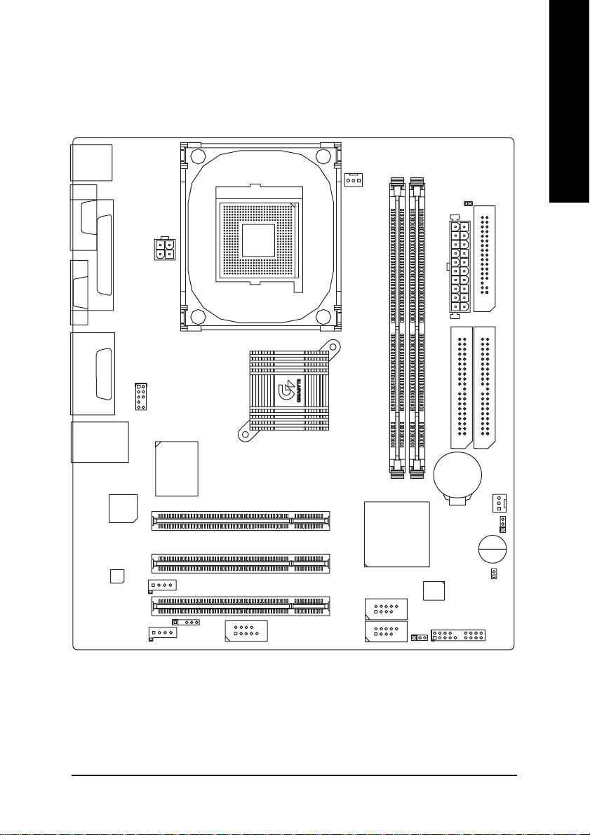
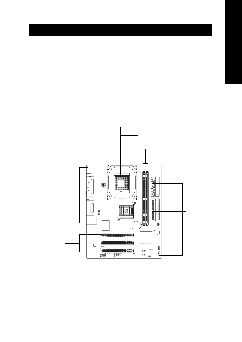
GA-8IMMT4 (Ver.1.0) Motherboard Layout
KB_MS
English
VGA
LINE_OUTMIC_IN
COMA
LINE_IN
LAN
LPT
GAME
USB
RTL8100BL
CODEC
CD_IN
ATX_12V
F_AUDIO
ITE8702
AUX_IN
IR
SOCKET478
Intel 845GL
COMB
PCI1
PCI2
PCI3
CPU_FAN
F_USB2
F_USB1
GA-8IMMT4
DIMM2
DIMM1
ICH4
PWR_LED
BIOS
DIMM_LED
ATX
IDE2
BAT1
F_PANEL
FDD
IDE1
SYS _FAN
CLR_COMS
Buzzer
CI
- 7 -
Introduction
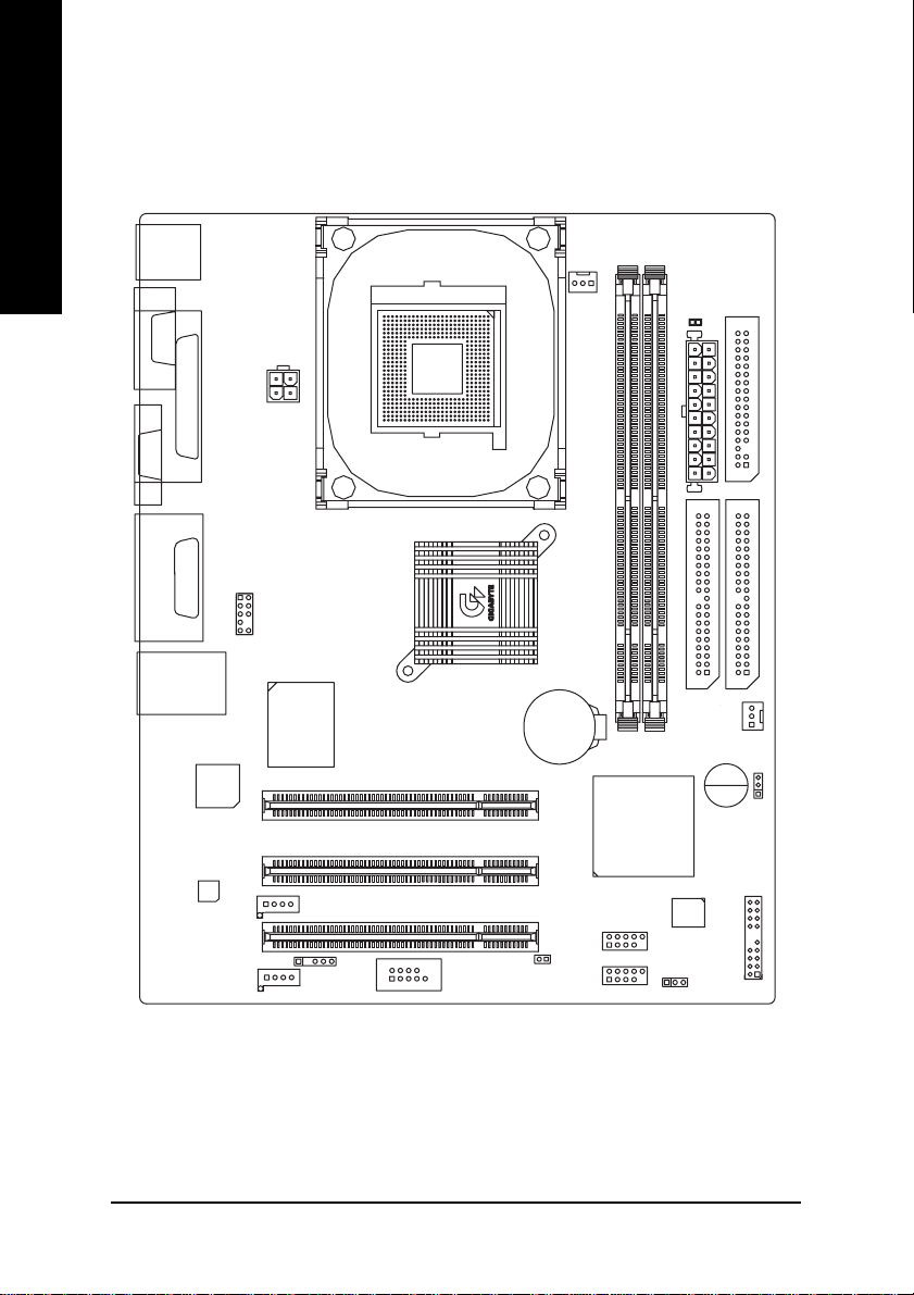
GA-8IMMT4 (Ver.1.1) Motherboard Layout
English
KB_MS
COMA
VGA
LINE_OUTMIC_IN
LAN
LINE_IN
LPT
GAME
USB
RTL
8100BL
CODEC
CD_IN
ATX_12V
F_AUDIO
ITE8702
AUX_IN
CPU_FAN
FDD
DIMM_LED
SOCKET478
ATX
GA-8IMMT4
Intel 845GL
IDE1
DIMM1
ICH4
IDE2
SYS _FAN
DIMM2
Buzzer
CLR_COMS
F_PANEL
BIOS
PWR_LED
BAT1
PCI1
PCI2
PCI3
F_USB2
CI
IR
COMB
F_USB1
- 8 -GA-8IMMT4 Motherboard
Chapter 2 Hardware Installation Process
T o set up your computer , you must complete the following steps:
Step 1- Install the Central Processing Unit (CPU)
Step 2- Install memory modules
Step 3- Install expansion cards
Step 4- Connect ribbon cables, cabinet wires and power supply
Step 5- Setup BIOS software
Step 6- Install supporting software tools
Step 1
Step 4
Step 2
English
Step 4
Step 3
Step 4
- 9 - Hardware Installation Process
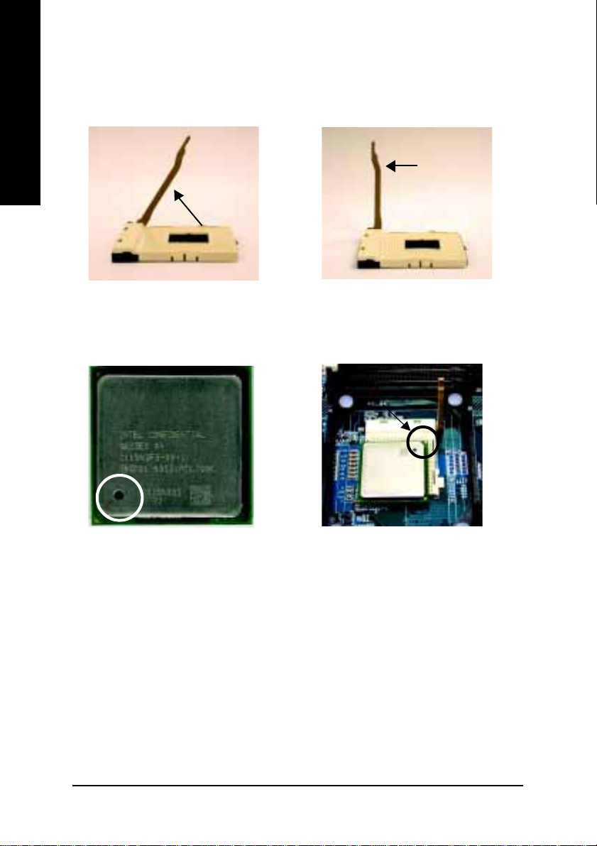
Step 1: Install the Central Processing Unit (CPU)
Step1-1: CPU Installation
English
Angling the
rod to 65
1. Angling the rod to 65-degree maybe
feel a kind of tight , and then continue
pull the rod to 90-degree when a noise
“cough” made.
0
Pin1 indicator
3. CPU Top View
Socket
Actuation
Lever
2. Pull the rod to the 90-degree directly .
Pin1 indicator
4. Locate Pin 1 in the socket and look
for a (golden) cut edge on the CPU
upper corner. Then insert the CPU
into the socket.
00
0 Please make sure the CPU type is supported by the motherboard.
00
00
0 If you do not match the CPU socket Pin 1 and CPU cut edge well, it will cause
00
improper installation. Please change the insert orientation.
- 10 -GA-8IMMT4 Motherboard
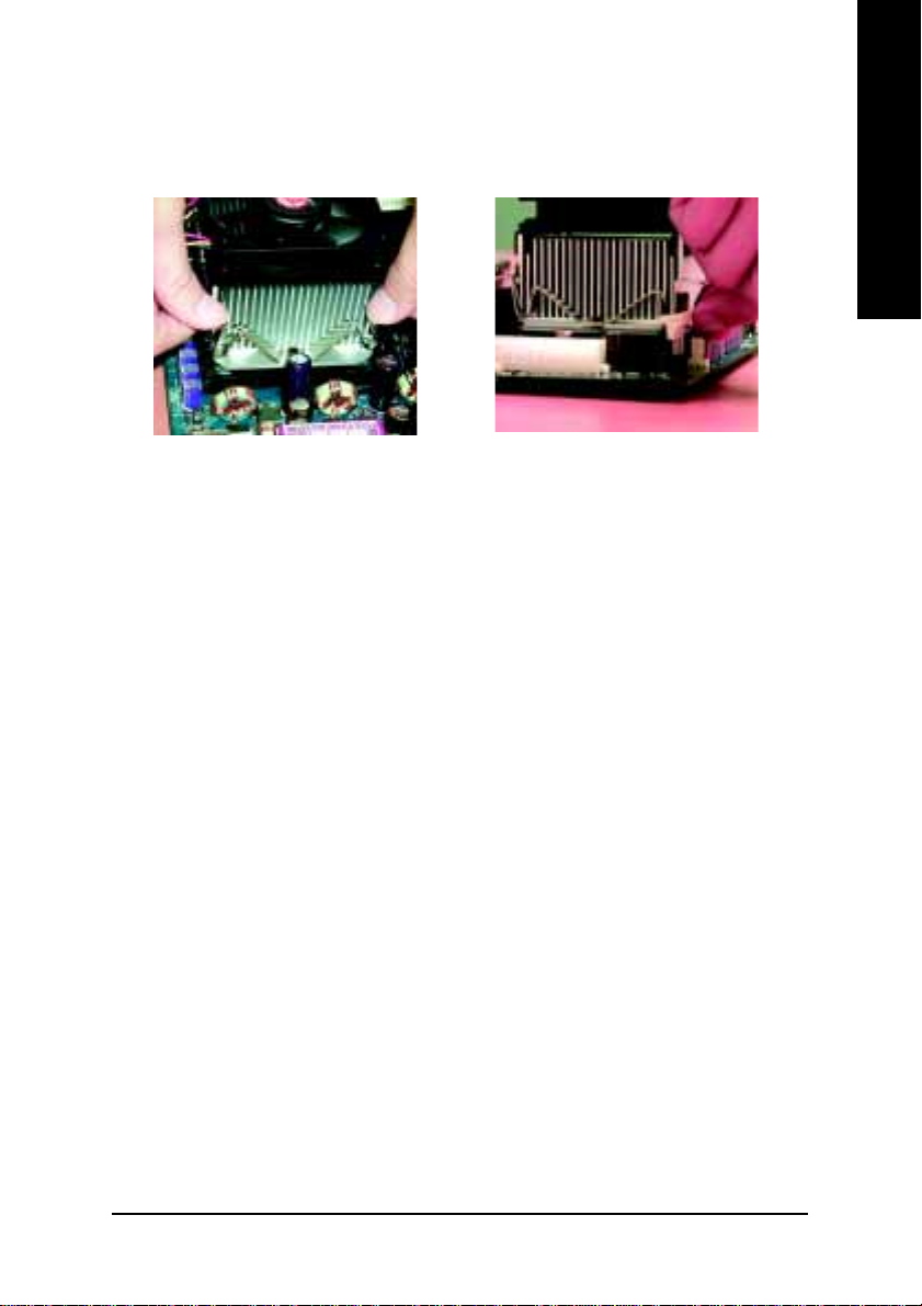
Step 1-2 : CPU Heat Sink Installation
English
1. Hook one end of the cooler bracket
to the CPU socket first.
00
0 Please use Intel approved cooling fan.
00
00
0 We recommend you to apply the thermal tape to provide better heat conduc-
00
2. Hook the other end of the cooler
bracket to the CPU socket.
tion between your CPU and heatsink.
(The CPU cooling fan might stick to the CPU due to the hardening of the
thermal paste. During this condition if you try to remove the cooling fan, you
might pull the processor out of the CPU socket alone with the cooling fan,
and might damage the processor. To avoid this from happening, we suggest
you to either use thermal tape instead of thermal paste, or remove the cooling
fan with extreme caution.)
00
0 Make sure the CPU fan power cable is plugged in to the CPU fan connector,
00
this completes the installation.
00
0 Please refer to CPU heat sink user’s manual for more detail installation
00
procedure.
- 11 - Hardware Installation Process
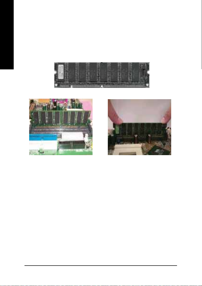
Step 2: Install memory modules
The motherboard has 2 dual in-line memory module (DIMM) sockets support 4 banks. The BIOS will
English
automatically detects memory type and size. T o install the memory module, just push it vertically into
the DIMM socket. The DIMM module can only fit in one direction due to the two notch. Memory size
can vary between sockets.
SDRAM
1. The DIMM socket has two notch, so
the DIMM memory module can only fit
in one direction.
3. Close the plastic clip at both edges of the DIMM sockets to lock the DIMM module.
Reverse the installation steps when you wish to remove the DIMM module.
00
0 When RAM LED is ON, do not install/remove SDRAM from socket.
00
00
0 Please note that the DIMM module can only fit in one direction due to the two
00
2. Insert the DIMM memory module vertically into the DIMM socket. Then push
it down.
notches. Wrong orientation will cause improper installation. Please change
the insert orientation.
- 12 -GA-8IMMT4 Motherboard
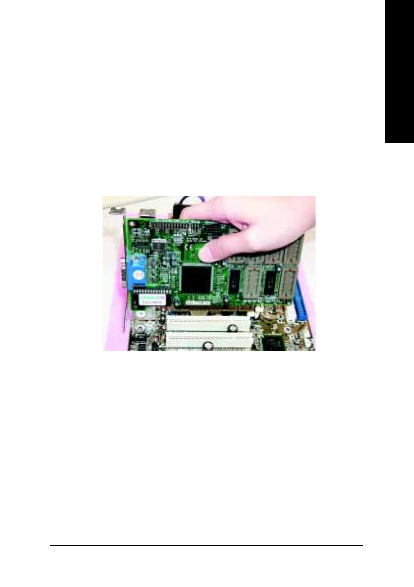
Step 3: Install expansion cards
1. Read the related expansion card’s instruction document before install the expansion card into
the computer.
2. Remove your computer’s chassis cover, screws and slot bracket from the computer.
3. Press the expansion card firmly into expansion slot in motherboard.
4. Be sure the metal contacts on the card are indeed seated in the slot.
5. Replace the screw to secure the slot bracket of the expansion card.
6. Replace your computer’s chassis cover.
7. Power on the computer, if necessary, setup BIOS utility of expansion card from BIOS.
8. Install related driver from the operating system.
English
- 13 - Hardware Installation Process
Step 4: Connect ribbon cables, cabinet wires and power
English
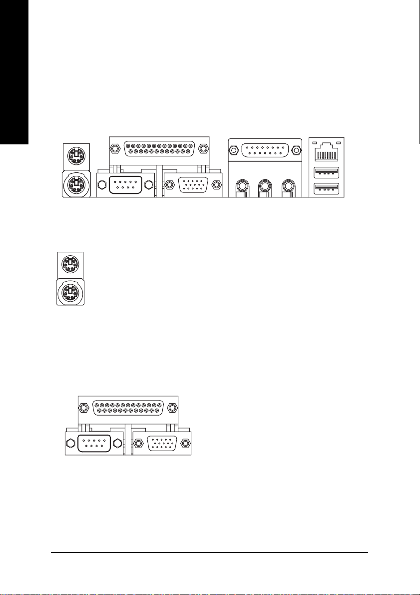
Step4-1 : I/O Back Panel Introduction
supply
X
XX
X PS/2 Keyboard and PS/2 Mouse Connector
XX
YY
Y Parallel Port, Serial Ports and VGA port (LPT/COMA/VGA)
YY
Y
PS/2 Mouse Connector
(6 pin Female)
PS/2 Keyboard Connector
(6 pin Female)
Parallel Port
(25 pin Female)
COMA VGA
Serial Port
(9 pin Male)
VGA Port
(15 pin Female)
Z
[
¾ This connector supports standard PS/2
keyboard and PS/2 mouse.
¾ This motherboard supports 1 standard COM
port, 1 LPT port and 1 VGA port. Device like
printer can be connected to LPT port; mouse
and modem etc. can be connected to COM
port.
\
- 14 -GA-8IMMT4 Motherboard
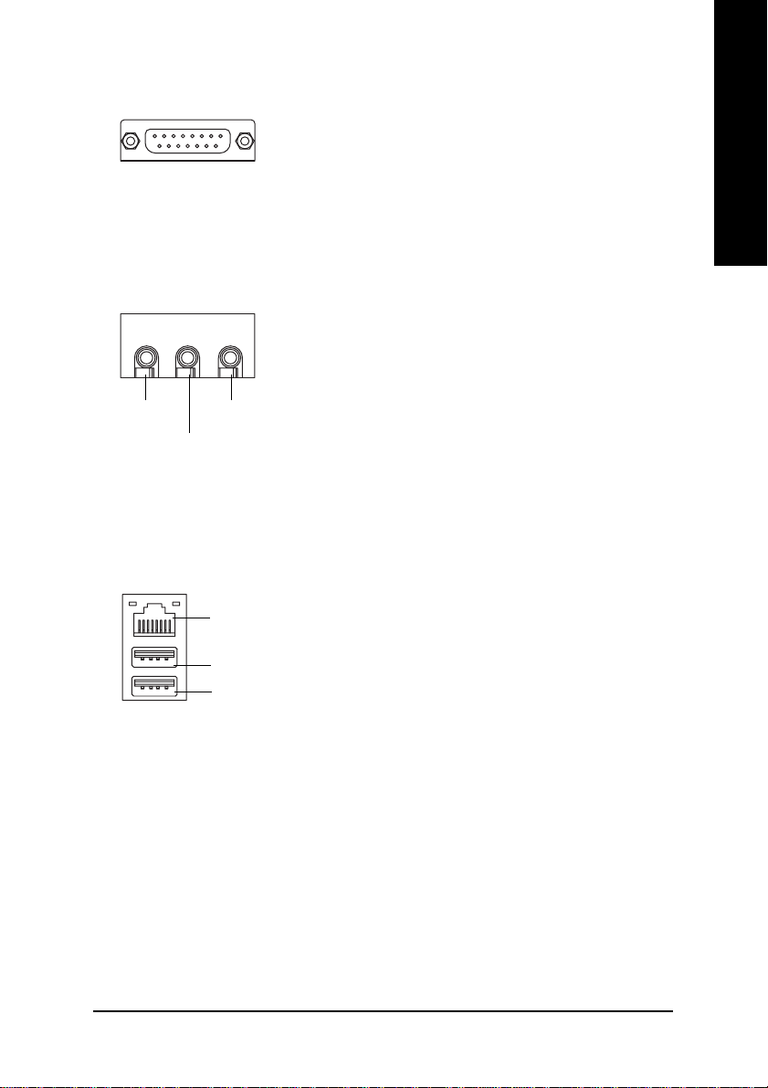
ZZ
Z Game /MIDI Ports
ZZ
Joystick / MIDI (15 pin Female)
[[
[ Audio Connectors
[[
Line Out
\\
\ USB/LAN Connector
\\
MIC In
Line In
LAN Connector
USB 0
USB 1
English
¾ This connector supports joystick, MIDI keyboard
and other relate audio devices.
¾ After install onboard audio driver, you may con-
nect speaker to Line Out jack, micro phone to
MIC In jack.
Device like CD-ROM, walkman etc. can be
connected to Line-In jack.
¾ Before you connect your device(s) into USB
connector(s), please make sure your device(s) such
as USB keyboard, mouse, scanner, zip, speaker...
etc. Have a standard USB interface. Also make
sure your OS supports USB controller. If your OS
does not support USB controller, please contact
OS vendor for possible patch or driver upgrade. For
more information please contact your OS or
device(s) vendors.
- 15 - Hardware Installation Process
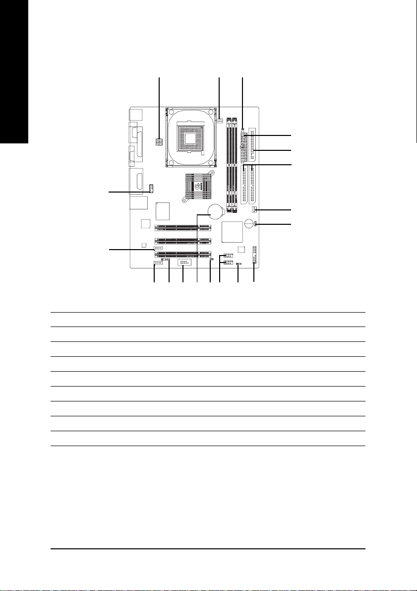
Step4-2 : Connectors Introduction
English
10
12
1) CPU_FAN
2) SYS_FAN
3) ATX_12V
4) ATX
5) IDE1 / IDE2
6) FDD
7) DIMM_LED
8) PWR_LED
9) F_PANEL
3 1
18
14 13
11
7
9
815
16
10) F_AUDIO
11) CD_IN
12) AUX_IN
13) F_USB1 / F_USB2
14) COMB
15) IR
16) CI
17) CLR_COMS
18) BAT1
4
6
5
2
17
- 16 -GA-8IMMT4 Motherboard
1) CPU_FAN (CPU FAN Connector)
1
Sense
GND
+12V/Control
¾ Please note, a proper installation of the CPU
cooler is essential to prevent the CPU from
running under abnormal condition or damaged
by overheating. The CPU fan connector supports Max. current up to 600 mA.
English
PS-ON
2) SYS_FAN (System FAN Connector)
Sense
+12V/Control
1
GND
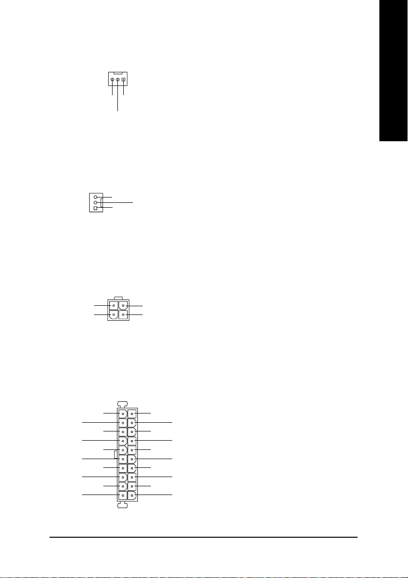
3) ATX_12V (+12V Power Connector)
4
3
+12V
GND
+12V
GND
21
4) ATX (ATX Power Connector)
1
-12V
(Soft On/Off)
GND
-5V
VCC
3.3V
GND
GND
GND
VCC
3.3V
GND
GND
GND
5V SB
¾ This connector allows you to link with the cool-
¾ This connector (ATX +12V) supplies the CPU
¾ AC power cord should only be connected to
3.3V
VCC
VCC
Power Good
(Stand by +5V)
+12V
ing fan on the system case to lower the system
temperature.
operation voltage (Vcore). If this "ATX+ 12V
connector" is not connected, system cannot
boot.
your power supply unit after A TX power cable
and other related devices are firmly connected
to the motherboard.
20
- 17 - Hardware Installation Process
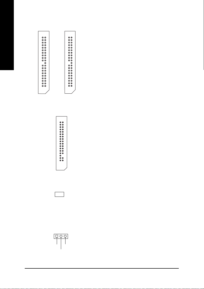
5) IDE1 / IDE2 (IDE1 / IDE2 Connector)
English
¾ Important Notice:
Please connect first hard disk to IDE1 and
connect CD-ROM to IDE2.
The red stripe of the ribbon cable must be the
same side with the Pin1.
1
IDE2
IDE1
6) FDD (Floppy Connector)
1
7) DIMM_LED
_
+
8) PWR_LED
1
MPD+
MPD-
MPD-
1
¾ Please connect the floppy drive ribbon cables
to FDD. It supports 360K, 1.2M, 720K, 1.44M
and 2.88M bytes floppy disk types.
The red stripe of the ribbon cable must be the
same side with the Pin1.
¾ Do not remove memory modules while
DIMM LED is on. It might cause short or other
unexpected damages due to the 3.3V stand
by voltage. Remove memory modules only
when STR function is disabled by jumper and
AC Power cord is disconnected.
¾ PWR_LED is connect with the system power
indicator to indicate whether the system is
on/off. It will blink when the system enters
suspend mode.
If you use dual color LED, power LED will turn
to another color.
- 18 -GA-8IMMT4 Motherboard
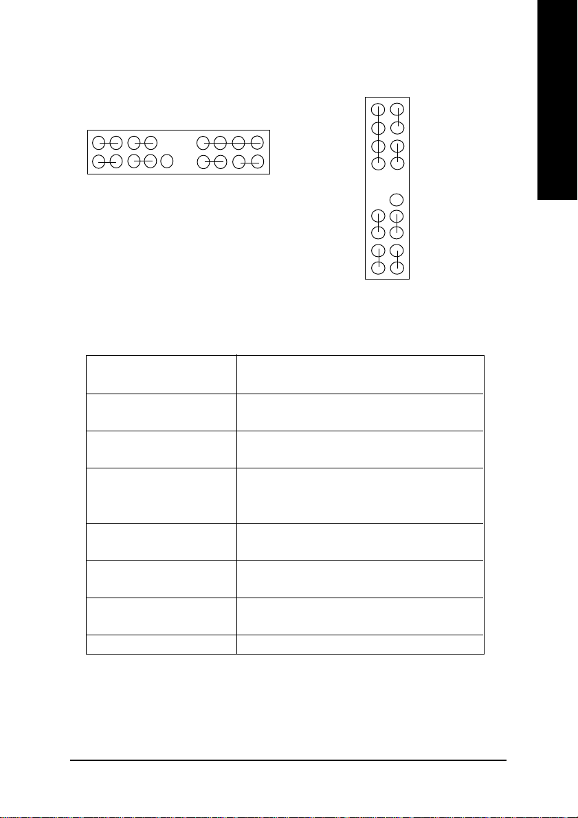
9) F_PANEL (2x10 Pins Connector)
MSG+
1
1
2
1
GN (Green Switch) Open: Normal Operation
GD (Green LED) Pin 1: LED anode(+)
HD (IDE Hard Disk Active LED) Pin 1: LED anode(+)
SPK (Speaker Connector) Pin 1: VCC(+)
RES (Reset Switch) Open: Normal Operation
PW (Soft Power Connector) Open: Normal Operation
MSG(Message LED/Power/ Pin 1: LED anode(+)
Sleep LED) Pin 2: LED cathode(-)
NC NC
1
HD+
HD-
1
RST+
RST-
In PCB ver. 1.0
NC
SPK+
1
1
GD+
PW-
PW+
MSG-
SPK-
20
19
1
GN-
GN+
GD-
Close: Entering Green Mode
Pin 2: LED cathode(-)
Pin 2: LED cathode(-)
Pin 2- Pin 3: NC
Pin 4: Data(-)
Close: Reset Hardware System
Close: Power On/Off
SPK-
SPK+
1
PW-
PW+
1
MSG-
1
MSG+
In PCB ver. 1.1
2201
English
19
GN-
1
GN+
GD-
1
GD+
NC
RST-
1
RST+
HD-
1
HD+
¾ Please connect the power LED, PC speaker, reset switch and power switch etc of your chassis
front panel to the F_PANEL connector according to the pin assignment above.
- 19 - Hardware Installation Process

10) F_AUDIO (F_AUDIO Connector)
English
Front Audio (R)
Front Audio (L)
REF
Reserved
MIC
¾ If you want to use Front Audio connector, you
must remove 5-6, 9-10 Jumper.
In order to utilize the front audio header, your
1
GND
POWER
Rear Audio (R)
Rear Audio (L)
chassis must have front audio connector. Also
please make sure the pin assigment on the
cable is the same as the pin assigment on the
MB header. To find out if the chassis you are
buying support front audio connector, please
contact your dealer.
11) CD_IN (CD In Connector)
1
CD-L
CD-R
GND
12) AUX_IN (AUX In Connector)
1
AUX-L
AUX-R
GND
¾ Connect CD-ROM or DVD-ROM audio out to
the connector.
¾ Connect other device (such as PCI TV Tunner
audio out) to the connector.
- 20 -GA-8IMMT4 Motherboard

13) F_USB1 / F_USB2 (Front USB Connector)
(F_USB1 & F_USB2 connectors in yellow are for USB 2.0)
¾ Be careful with the polarity of the front USB
connector. Check the pin assignment while
you connect the front USB cable. Please
contact your nearest dealer for optional front
USB 2.0 cable.
Power
1
USB Dy+
USB Dy-
GND
USB Over
Current
English
14) COMB
15) IR
Power
1
USB Dx-
USB Dx+
NDTRB-
NSINB
1
NDCDB-
NSOUTB
GND
NDSRB-
GND
NCTSB-
NC
NRIB-
NRTSB-
¾ Be careful with the polarity of the COMB
connector. Check the pin assignment while
you connect the COMB cable. Please contact
your nearest dealer for optional COMB cable.
¾ Be careful with the polarity of the IR connector
while you connect the IR. Please contact your
nearest dealer for optional IR device.
VCC(+5V)
IR Data Input
IR Data Output
GND
- 21 - Hardware Installation Process

16) CI (CASE OPEN)
English
1
GND
Signal
GND
In PCB ver. 1.0 In PCB ver. 1.1
1
Signal
¾ This 2-pin connector allows your system to en-
able or disable the “Case Open” item in BIOS,
if the system case begin remove.
17) CLR_CMOS (Clear CMOS)
1
1
1-2 close: Clear CMOS
Open: Normal
18) BA T1 (Battery)
+
#
¾ You may clear the CMOS data to its default
values by this jumper.
T o clear CMOS, temporarily short 1-2 pin.
# Default doesn’t include the “Shunter” to
prevent from improper use this jumper.
CAUTION
Danger of explosion if battery is incorrectly
replaced.
Replace only with the same or equivalent type
recommended by the manufacturer.
Dispose of used batteries according to the
manufacturer’s instructions.
- 22 -GA-8IMMT4 Motherboard

English
- 23 - Hardware Installation Process
 Loading...