


 A G P
A G P
A G P 4 X |
( |
) |
A G P 4 X ( 1 . 5 V ) |
|
|

 AGP 2X (3.3V)
 Intel® 845(E/G)/850 (E)


 AGP 2X(3.3V)

 AGP 2X(3.3V)


 Diamond Vipper V770


 2X/4X
2X/4X 


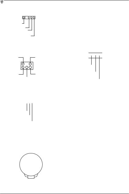
 Jumper


 2X
2X  4X
4X 


 2X(3.3V)


GA-8IEML-T(-C)


 Jumper

 4X (1.5V)


 SiS 305
  Power Color


 ATi Rage 128 Pro


 2X/4X
2X/4X 


 2X(3.3V)


GA-8IEML-T(-C)


 AG32S(G)


ATi Rage 128 Pro 


 AGP4X
AGP4X 


DECLARATION OF CONFORMITY
Per FCC Part 2 Section 2.1077(a)
Responsible Party Name: G.B.T.INC.(U.S.A.)
Address: 17358 Railroad Street City of Industry, CA 91748
Phone/FaxNo: (818) 854-9338/ (818) 854-9339 hereby declares that the product
ProductName: Motherboard
ModelNumber: GA-8IEML-T
Conforms to the following specifications:
FCC Part 15, Subpart B, Section 15.107(a) and Section 15.109(a),
Class B Digital Device
SupplementaryInformation:
This device complies with part 15 of the FCC Rules. Operation is subject to the following two conditions: (1) This device may not cause harmful and (2) this device must accept any inference received, including that may cause undesired operation.
Representative Person’s Name: ERIC LU
Signature: Eric Lu
Date: May 20,2002

EN 55011
EN 55013
EN 55014
EN 55015
EN 55020
7 EN 55022
DIN VDE 0855
part 10
part 12
7 CE marking
EN 60065
EN 60335
Declaration of Conformity
We, Manufacturer/Importer
(full address)
G.B.T. Technology Träding GMbH
Ausschlager Weg 41, 1F, 20537 Hamburg, Germany
declare that the product
( description of the apparatus, system, installation to which it refers)
Mother Board
GA-8IEML-T
is in conformity with
(reference to the specification under which conformity is declared) in accordance with 89/336 EEC-EMC Directive
Limits and methods of measurement of radio disturbance characteristics of industrial,scientific and medical (ISM high frequency equipment
Limits and methods of measurement of radio disturbance characteristics of broadcast receivers and associated equipment
Limits and methods of measurement of radio disturbance characteristics of household electrical appliances, portable tools and similar electrical apparatus
Limits and methods of measurement of radio disturbance characteristics of fluorescent lamps and luminaries
Immunity from radio interference of broadcast receivers and associated equipment
Limits and methods of measurement of radio disturbance characteristics of information technology equipment
Cabled distribution systems; Equipment
for receiving and/or distribution from
sound and television signals
EN 61000-3-2* 7 EN 60555-2
EN 61000-3-3*
7EN 60555-3
7EN 50081-1
7EN 50082-1
EN 55081-2
EN 55082-2
ENV 55104
EN50091-2
Disturbances in supply systems cause by household appliances and similar electrical equipment armonics”
Disturbances in supply systems cause by household appliances and similar
electrical equipment “Voltage fluctuations”
Generic emission standard Part 1: Residual commercial and light industry
Generic immunity standard Part 1: Residual commercial and light industry
Generic emission standard Part 2: Industrial environment
Generic emission standard Part 2: Industrial environment
lmmunity requirements for household appliances tools and similar apparatus
EMC requirements for uninterruptible power systems (UPS)
(EC conformity marking)
The manufacturer also declares the conformity of above mentioned product with the actual required safety standards in accordance with LVD 73/23 EEC
Safety requirements for mains operated |
EN 60950 |
|
electronic and related apparatus for |
|
|
household and similar general use |
|
|
Safety of household and similar |
EN 50091-1 |
|
electrical appliances |
|
|
|
Manufacturer/Importer |
|
|
Date : May 20, 2002 |
Signature: |
(Stamp) |
Name: |
|
|
|
Timmy Huang
Timmy Huang

GA-8IEML-T  P4
P4 


Pentium®4


Rev. 2011 12MC-8IEMLT-2011

GA-8IEML-T 


|
............................................................................ |
|
4 |
............................................................................ |
|
|
4 |
....................................................................... |
|
|
5 |
.................................................................................................... |
|
|
5 |
GA-8IEML-T ........................................................ |
|
Layout |
7 |
.................................................... |
|
|
8 |
1 .......................................................... |
|
(CPU) |
9 |
1-1 ................................................................................... |
|
|
9 |
1-2 ................................................................ |
|
|
10 |
2 ................................................................... |
|
|
11 |
3 ............................................................................ |
|
|
12 |
4 : |
|
|
13 |
4-1 ........................................................................... |
I/O |
|
13 |
4-2 ................................................................................................... |
|
|
15 |
4-3 ................................................................................................... |
|
|
21 |
BIOS .................................................. |
|
23 |
|
..................................................... |
(BIOS |
F1) |
24 |
CMOS ..................................................................................... |
|
|
26 |
BIOS .............................................................................. |
|
|
29 |
......................................................................................... |
|
|
31 |
2

......................................................................................... |
|
36 |
P C I ................................................................... |
|
39 |
......................................................................................... |
|
40 |
/ ...................................................................................... |
|
42 |
.................................................................................................. |
|
44 |
Fail-Safe ............................................................................. |
|
45 |
Optimized ........................................................................... |
|
46 |
(Supervisor)/ |
(User) ..................................... |
47 |
SETUP ............................................................ |
|
48 |
SETUP |
....................................................... |
49 |
......................................... |
50 |
............................................................................... |
50 |
Q-Flash Utility .................................................................................... |
51 |
Easy TuneTM 4 ................................................................................... |
53 |
@ BIOSTM ........................................................................................... |
54 |
..................................................................... |
55 |
3
GA-8IEML-T 


;GA-8IEML-T  GA-8IEML-T-C


;

 x 1 /
x 1 / 

 x 1
x 1
;


;GA-8IEML-T 


; I/O
I/O 

1.


2.


3.


 (CPU
(CPU  RAM)
RAM)


4.


5.


 ATX
ATX


 PCB
PCB


4

|
|
|
|
|
|
|
|
|
|
z |
|
Micron ATX |
24.4 |
x 21 |
z GA-8IEML-T |
|
|
|
|
|
GA-8IEML-T |
GA-8IEML-T-C |
|
|
|
|
|
||
z |
Socket478 |
Intel Micro FC-PGA2 Pentium®4 |
||
z Intel® Pentium ® 4 (Northwood, 0.13
 m)
m) 

zIntel Pentium® 4 400/533MHz FSB
z2nd 


 CPU
CPU
z Chipset 82845E HOST/AGP/Controller
z Intel ICH4 I/O Controller Hub
z 2 184-pin DDR DIMM
z DDR266/200 SDRAM
z

 2GB
2GB
z
 2.5V DDR DIMM
z 64bit ECC type DRAM integrity
I/O |
z |
Winbond W83627HF |
|
|
||
|
z |
1 |
AGP |
4X(1.5V) |
|
|
|
z |
3 PCI |
33MHz |
PCI2.2 compliant |
|
|
|
|
|
|
|
||
IDE |
z |
2 |
IDE bus master (UDMA 33/ATA 66/ATA 100) IDE |
|
||
|
|
4 ATAPI |
|
|
|
|
|
z |
|
PIO mode 3,4(UDMA33/ATA66/ATA100) IDE |
ATAPI |
||
|
|
CD-ROM |
|
|
|
|
|
|
|
|
|
|
|
|
z |
1 |
|
|
(360K,720K,1.2M,1.44M |
|
|
|
|
2.88M bytes) |
|
|
|
|
z |
1 |
|
Normal/EPP/ECP |
|
|
|
z |
2 |
|
(COM A & COM B) |
|
|
|
z |
|
USB 2.0/1.1 (6 USB |
, |
x 2, |
|
|
|
|
|
x 4) |
|
|
|
z |
1 |
|
|
|
|
|
|
|
|
|
|
|

 .......
5

GA-8IEML-T 


|
z |
CPU / |
|
|
|
|
|
z |
CPU / |
|
|
|
|
|
z |
|
|
|
|
|
|
|
|
|
|
|
|
|
z |
CODEC |
|
|
(RealTek ALC650) |
|
|
z |
Line Out : 2 |
|
|
|
|
|
z |
Line In : 2 |
|
|
( |
) |
|
z |
Mic In : |
|
/ |
( |
) |
|
z |
SPDIF out : |
|
|
|
|
|
z |
CD_In/AUX_IN/Game Port |
|
|||
|
|
|
|
|
|
|
PS/2 |
z |
PS/2 |
|
|
PS/2 |
|
BIOS |
z |
|
|
AWARD BIOS |
2M bit |
|
|
z |
RTL8100(B)L |
|
|||
|
z |
PS/2 |
|
|
|
|
|
z |
PS/2 |
|
|
|
|
|
z |
STR |
|
|
(Suspend-To-RAM) |
|
|
z |
AC Recovery |
|
|
|
|
|
z |
USB |
/ |
|
wake up from S3 |
|
|
z |
@BIOS |
|
|
|
|
|
z |
Easy Tune 4 |
|
|||
|
|
|
|
|
|
|
0 

 CPU
CPU 

 CPU
CPU 


 CPU
CPU 


"*"  GA-8IEML-T


6

GA-8IEML-T 

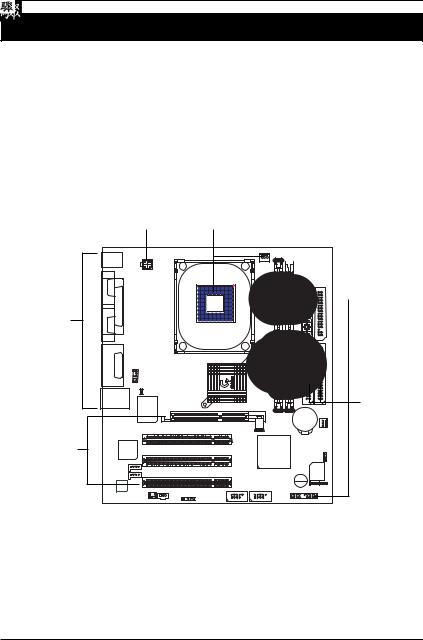
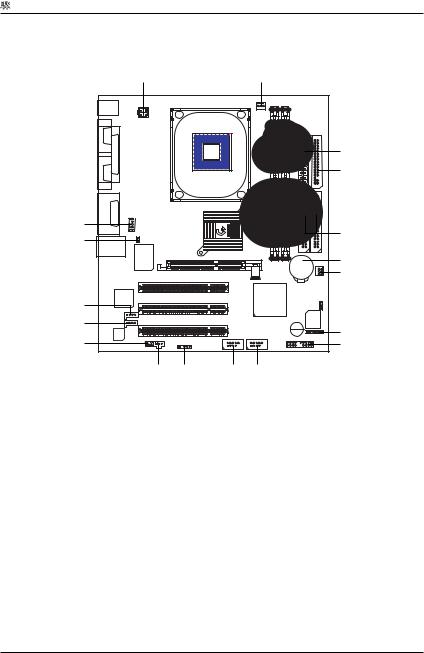
 Layout
KB_MS
COMA |
|
|
LPT |
COMB |
|
IN LINE_OUT LINE_IN |
GAME |
MIC_ |
|
USB |
LAN* |
ATX_12V
F_AUDIO
CI
W83627HF
SOCKET478
82845E
PCI1
CPU_FAN
GA-8IEML-T(-C)
AGP |
DDR1 |
ATX |
FDD |
IDE2 |
IDE1 |
 DDR2
DDR2
BAT
SYS_FAN
RTL8100* |
|
PCI2 |
ICH4 |
BIOS_WP |
AUX_IN |
|
PCI3 |
|
FWH |
CD_IN |
|
|
||
|
|
BUZZER |
||
CODEC |
|
|
||
|
F_USB1 |
F_USB2 |
F_PANEL |
|
SUR_CEN |
SPDIF |
|
|
|
IR |
|
|
||
|
|
|
|
|
CLR_CMOS
PWR_LED
"*"  GA-8IEML-T


7
GA-8IEML-T 


 1 -
1 - 


 (CPU)
(CPU)
 2 -
2 - 


 3 -
3 - 


 4 -
4 - 


 5 -
5 -  BIOS
BIOS 

 6 -
6 - 


4 |
1 |
|
2 |
|
|
|
|
|
|
|
|
|
|
|
|
|
|
|
|
|
|
|
|
|
|
|
|
|
|
|
|
|
|
|
|
|
|
|
|
|
|
|
|
|
|
|
|
|
|
|
|
|
|
|
|
|
|
|
|

 4
4

 4
4

 3
3
8

 1
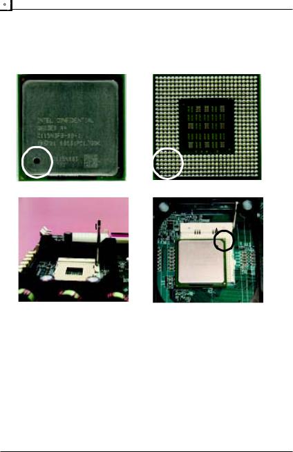
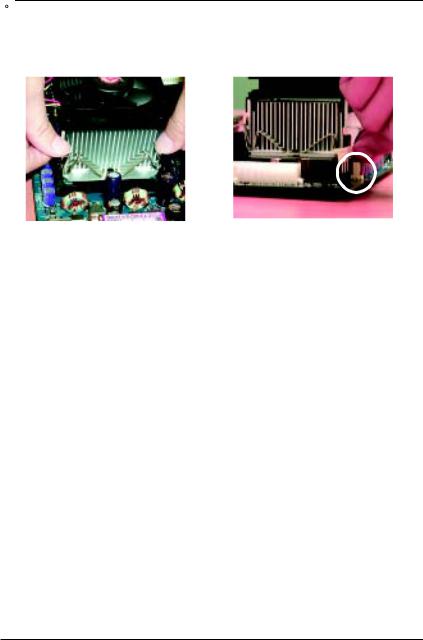
1


 (CPU)
(CPU)
 1-1
1-1


1 |
1 |
1
1. |
2. |
( |
90 |
|
) |
3. |
|
|
0


0C P U 


9
GA-8IEML-T 


 1-2
1-2


1. |
CPU |
2. |
CPU |
CPU 
0 


 I n t e l
0C P U 


( 


 C P U
C P U 


 C P U
C P U 


 C P U
C P U 


 )
)
0


0 C P U
C P U 


 C P U _ F A N


 (
( 


 )
)
1 0
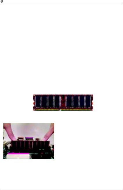

 2
2 


2 |
(DIMM) |
BIOS |
|
|
DIMM |
|
|
|
|
Unbuffered DDR DIMM |
|
|
||
64 Mbit (2Mx8x4 banks) |
|
64 Mbit (1Mx16x4 banks) |
128 Mbit(4Mx8x4 banks) |
|
128 Mbit(2Mx16x4 banks) |
|
256 Mbit(8Mx8x4 banks) |
256 Mbit(4Mx16x4 banks) |
|
512 Mbit(16Mx8x4 banks) |
|
512 Mbit(8Mx16x4 banks) |
|
|
: Intel 845E/G |
|
|
x16 DDR |
|
DDR
1. 


 2.
2. 


3. 


 DIMM
DIMM 


0 


1 1
GA-8IEML-T 


 3
3 


1.


2.


 (
(


 )
)
3.


4.


5.


6.


7.


 BIOS
BIOS 


8.


/ |
AGP |
AGP |
AGP |
AGP 


AGP 
1 2

 4
4


4-1 |
|
I/O |
|
X |
Y |
Z |
\ |
|
|
|
|
|
|
[ |
|
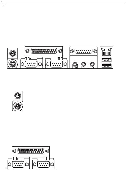
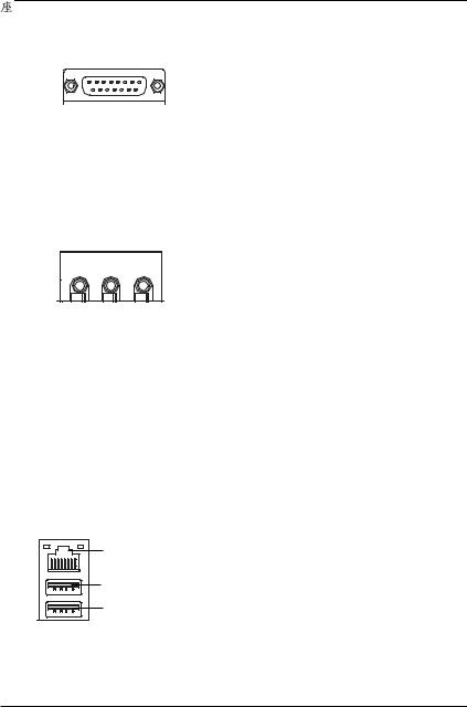
X PS/2 |
PS/2 |
PS/2 
 (6 pin Female) PS/2
 (6 pin Female)
¾


 PS/2
PS/2 

 PS/2
PS/2


Y 

 A /
A / 

 B /
B / 


(25 pin Female) |
¾ |

 A
A 
 B (9 pin Male)
1 3
GA-8IEML-T 


Z GAME/MIDI Ports (


 )
)
¾ 


GAME/MIDI
(15 pin Female)
[ Audio Connector (
 )
)
¾ 


|
|
|
|
LINE OUT |
MIC IN |
||
|
|
|
|
LINE IN
\ 


 ,
, 


 *
*
¾ 


LAN ( |
)* |
USB |
USB |
USB |

 USB ZIP
  USB
USB 
 .
.
USB 1(

 1)
1)
USB 0 (

 0)
0)
USB 


"*"  GA-8IEML-T


1 4
 4-2
4-2


A B
R
Q
P
O
N
M L K J
C D
E
F G
H
I
A) |
ATX_12V |
J) |
F_USB2 |
B) |
CPU_FAN |
K) |
F_USB1 |
C) |
ATX |
L) |
IR |
D) |
FDD |
M) |
SPDIF |
E) |
IDE1/IDE2 |
N) |
SUR_CEN |
F) |
BAT |
O) |
CD_IN |
G) |
SYS_FAN |
P) |
AUX_IN |
H) |
PWR_LED |
Q) |
CI |
I) |
F_PANEL |
R) |
F_AUDIO |
1 5
GA-8IEML-T 


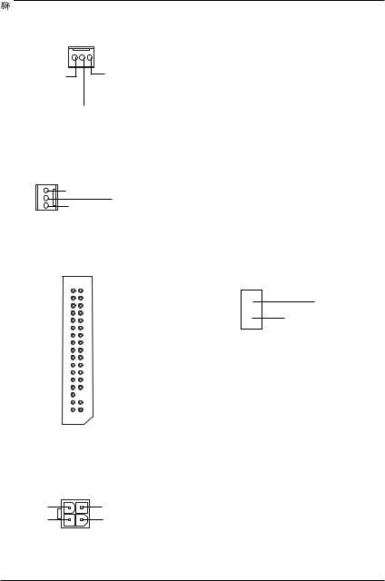
B) CPU_FAN (CPU |
|
) |
|
¾ |
|
1 |
|
|
+12V/Control |
CPU |
|
|
|
600 |
G) SYS_FAN ( |
|
) |
|
¾ |
AGP PCI |
1 |
+12V/Control |
|
|
|
|
D) FDD (

 )
)
1
A) ATX_12V (+12V 
 )
)
4 2
+12V
+12V
3 1
Q ) C I ( 


 )
)
1 
¾


 ATX +12V


 CPU
CPU 


 ATX+12V


1 6
E)IDE1/IDE2 (


 IDE
IDE  )
)
¾

 :
:


 IDE
IDE


 IDE
IDE 
IDE |
IDE |
1 1
C) ATX_POWER (ATX Power |
) |
|
|
|
|
|
3.3V |
3.3V |
|
|
|
|
1 |
|
|
-12V |
3.3V |
|
|
|
PS-ON(Soft On/Off) |
VCC |
|
|
|
|
|
VCC |
|
|
VCC |
-5V |
5V SB (Stand by +5V) |
|
|
|
|||
|
VCC |
+12V |
|
|
|
|
20 |
|
|
¾ |
AC |
(110/220V) |
ATX |
|
|
ATX |
|
AC |
(110/220V) |
1 7
GA-8IEML-T 


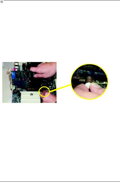
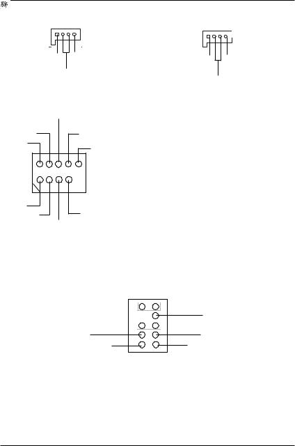
O) CD_IN ( |
) |
P) AUX_IN ( |
) |
1 |
|
1 |
|
J/K) F_USB1/F_USB2 ( |
|
) |
USB Dy+ |
|
|
USB Dy- |
¾ |
USB |
|
USB |
|
USB Over Current |
|
|
|
USB |
|
|
|
|
1 |
|
|
USB Dx- |
|
|
USB Dx+ |
|
|
R) F_AUDIO (


 )
)
10 9
Rear Audio (L)
 Front Audio (L)
Reserved
Rear Audio (R)
 Front Audio (R)
REF
MIC
21
¾


 :
:


 Pin5-6
  Pin9-10
 Jumper
1 8
I) F_PANEL ( |
|
|
|
) |
|
|
|
|
|
|
|
|
|
|
|
|
|
|||||||
|
|
GN- |
GN+ GD- |
GD+ |
RSV RST+ RST- |
HD- |
HD+ |
|
|
|||||||||||||||
19 |
|
|
|
|
1 |
|
|
1 |
|
1 |
|
|
|
|
|
|
|
1 |
1 |
|
|
|||
|
|
|
|
|
|
|
|
|
|
|
|
|
|
|
||||||||||
20 |
|
|
|
|
|
|
|
|
1 |
|
|
1 |
|
|
|
|
1 |
2 |
|
|
||||
|
|
|
|
|
|
|
|
|
|
|
|
|
|
|
|
|
||||||||
|
|
|
|
|
|
|
|
|
|
|
|
|
|
|
|
|
|
|
|
|
|
|
|
|
|
|
SPK- |
|
|
|
SPK+ |
PWPW+ |
MPD- |
MPD+ |
|
|
|||||||||||||
|
|
|
|
|
|
|
|
|
|
|
|
|
|
|
|
|
|
|
|
|
|
|||
|
GN (Green Switch) |
|
|
|
|
|
|
Open: Normal Operation |
|
|
||||||||||||||
|
|
|
|
|
|
|
|
|
|
|
Close: Entering Green Mode |
|
||||||||||||
|
|
|
|
|
|
|
|
|
|
|
|
|
|
|
|
|
|
|
|
|
|
|
||
|
GD (Green LED) |
|
|
|
|
|
|
Pin 1: LED anode(+) |
|
|
|
|
|
|
||||||||||
|
|
|
|
|
|
|
|
|
|
|
Pin 2: LED cathode(-) |
|
|
|||||||||||
|
|
|
|
|
|
|
|
|
0 |
|
|
|
|
|
|
|
|
|
|
|
|
|
||
|
|
|
|
|
|
|
|
|
|
|
|
|
|
|
|
|
|
|
|
|
|
|||
|
HD (IDE Hard Disk Active LED) |
|
|
|
Pin 1: LED anode(+) |
|
|
|
|
|
|
|||||||||||||
|
|
|
|
|
|
|
|
|
|
|
Pin 2: LED cathode(-) |
|
|
|||||||||||
|
|
|
|
|
|
|
|
|
0 |
|
|
|
|
|
|
|
|
|
|
|
|
|
||
|
|
|
|
|
|
|
|
|
|
|
|
|
|
|
|
|
|
|
|
|
|
|
||
|
SPK (Speaker Connector) |
|
|
|
|
|
|
Pin 1: VCC(+) +5v |
|
|
|
|
|
|
||||||||||
|
|
|
|
|
|
|
|
|
|
|
Pin 2- Pin 3: NC |
|
|
|
|
|
|
|
|
|
||||
|
|
|
|
|
|
|
|
|
|
|
Pin 4: Data(-) |
|
|
|
|
|
|
|
|
|
||||
|
|
|
|
|
|
|
|
|
|
|
|
|
|
|
|
|
|
|
|
|
|
|||
|
RST (Reset Switch) |
|
|
|
|
|
|
Open: Normal Operation |
|
|
||||||||||||||
|
|
|
|
|
|
|
|
|
|
|
Close: Reset Hardware System |
|||||||||||||
|
|
|
|
|
|
|
|
|
0 |
|
|
|
|
|
|
|
|
|
|
|
|
|
||
|
|
|
|
|
|
|
|
|
|
|
|
|
|
|
|
|
|
|
|
|
|
|||
|
PW (Soft Power Connector) |
|
|
|
|
|
|
Open: Normal Operation |
|
: |
||||||||||||||
|
|
|
|
|
|
|
|
|
|
|
Close: Power On/Off |
: |
/ |
|||||||||||
|
|
|
|
|
|
|
|
|
0 |
|
|
|
|
|
|
|
|
|
|
|
|
|
||
|
|
|
|
|
|
|
|
|
|
|
|
|
|
|
|
|
|
|
|
|
|
|
||
|
MPD (Message LED/Power/ |
|
|
|
|
|
|
Pin 1: LED anode(+) |
|
|
|
|
|
|
||||||||||
|
Sleep LED) |
|
|
|
|
|
|
Pin 2: LED cathode(-) |
|
|
||||||||||||||
|
|
|
|
|
|
|
|
|
0 |
|
|
|
|
|
|
|
|
|
|
|
|
|
||
|
|
|
|
|
|
|
|
|
|
|
|
|
|
|
|
|
|
|
|
|
|
|
|
|
|
RSV |
|
|
|
|
|
|
|
|
|
|
|
|
|
|
|
|
|
|
|
|
|||
¾ |
|
|
|
|
|
|
|
|
|
|
|
|
|
|
|
|
|
|
|
|
|
|
|
|
1 9
GA-8IEML-T 


L) IR (

 )
)


1 VCC
N) SUR_CEN
SUR OUTR |
LEF_OUT |
|
1 |
SUR OUTL |
CENTER_OUT |
|
GND |
M) SPDIF (SPDIF)
1 VCC
VCC
F) BAT( )
)
+
H) PWR_LED
1


MPD+
MPD-
MPD-
Sony/Philip Digital Interface Format
 /
/
SPDIF 


 (AC-3)


 (SPDIF In)


2 0
 4-3
4-3


1
2
1) CLR_CMOS |
2) BIOS_WP |
2 1
 Loading...