


GA-8IE800
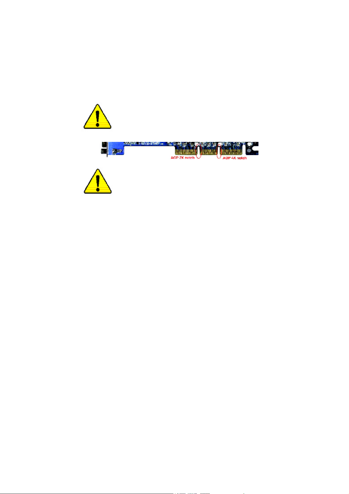
When you installing AGP card, please make sure the follow
ing notice is fully understood and practiced. If your AGP
card has "AGP 4X notch"(show below), please make sure
your AGP card is AGP 4X (1.5V).
Caution: AGP 2X(3.3V) card is not supported by Intel® 845
(E/G)/ Intel® 850(E) . You might experience system unable to
boot up normally. Please insert an AGP 4X(1.5V) card
Example 1: Diamond Vipper V770 golden finger is compatible
with 2X/4X mode AGP slot. It can be switched between AGP 2X
(3.3V) or 4X(1.5V) mode by adjusting the jumper. The factory
default for this card is 2X(3.3V). The GA-8IE800 (or any AGP 4X
only) motherboards might not function properly, if you install this card
without switching the jumper to 4X(1.5) mode in it.
Example 2: Some ATi Rage 128 Pro graphics cards made by
"Power Color", the graphics card manufacturer & some SiS 305
cards, their golden finger is compatible with 2X/4X mode AGP
slot, but they support 2X(3.3V) only.The GA-8IE800 (or any AGP
4X only) motherboards might not function properly, If you install this
card in it.
Note : Although Gigabyte's AG32S(G) graphics card is based on
ATi Rage 128 Pro chip, the design of AG32S(G) is compliance
with AGP 4X (1.5V) specification. Therefore, AG32S (G)will work
fine with Intel® 845(E/G) / 850(E) based motherboards.
M The author assumes no responsibility for any errors or omissions
that may appear in this document nor does the author make a
commitment to update the information contained herein.
M Third-party brands and names are the property of theirrespective
owners.
M Please do not remove any labels on motherboard, thismay void the
warranty of this motherboard.
M Due to rapid change in technology, some of the specifications might
be out of date before publication of this booklet.

Aussch lager Weg 41, 1F, 20537 Ham burg, Germa ny
( description o f the appa ratus, sy stem , install ation to whic h it refers)
(refere nce to the specifica tion und er wh ich co nformity is de clare d)
in accor dance with 89/ 336 EEC-E MC Directive
o EN 55011 Limits and methods of measurement
o EN 55013
o EN 55014 Limits and methods of measurement
o EN 55015 Limits and methods of measurement
o EN 55020
T EN 55022 Limits and methods of measurement
o DIN VDE 0 855
o part 10
o part 12
T CE mark ing
o EN 60065
o EN 60335
of radio disturbance characte ristics of
industrial,sci entific and medical (ISM
high frequency equipment
Limits and methods of measurement
of radio disturbance characte ristics of
broadcast receivers and associated
equipment
of radio disturbance characte ristics of
household electrical appliances,
portable tools and similar electrical
apparatus
of radio disturbance characte ristics of
fluorescent lamps and luminaries
Immun ity from radio interferen ce of
broadcast receivers and associated
equipment
of radio disturbance characte ristics of
information technology equipment
Cabled distrib ution systems; Equipment
for receiving and/or distr ibution fr om
sound and television signals
The manufacturer also declar es the confor mity of above mentioned pr oduct
with the actual r equir ed safety standar ds in accor dance with LVD 73/23 EEC
Safety requirements for mains operated
electronic and related apparatus for
household and similar general use
Safety of household and similar
electrical appliances
Declaration of Conformity
We, Man ufacturer /Importer
(full addr ess)
G.B.T. Technolo gy Träding GMbH
decl are that the produ ct
Mother Board
GA-8IE8 00
is in conformity w ith
o EN 61000-3-2*
T EN 60555-2
o EN 61000-3-3* Disturbances in su pply systems cause
T EN 60555-3
T EN 50081-1
T EN 50082-1
o EN 55081-2
o EN 55082-2
o ENV 55104
o EN50091-2
(EC conformity marking)
o EN 60950
o EN 50091-1
Manufacturer/Impor ter
Date : Jan. 17, 2003
Disturbances in su pply systems cause
by household appliances and similar
electrical equipment “Harmonics”
by household appliances and similar
electrical equipment “Voltage fluctuations”
Generic emission standard Part 1:
Residual commercial and light industry
Generic immunity standard Part 1:
Residual commercial and light industry
Generic emission standard Part 2:
Industrial environment
Generic emission standard Part 2:
Industrial environment
lmmuni ty requirements for hou sehold
appliances tools and similar apparatus
EMC requirements for uninterruptible
power syst ems (UPS)
Safety for information technology eq uipment
including electrical bussiness equipment
General and Safety requirments for
uninterruptible power syst ems (UPS)
Signature:
Name:
Timmy Huang
Timmy Huang

DECLARATION OF CONFORMITY
Per FCC Part 2 Section 2.1077(a)
Responsible PartName:
Address:
Phone/Fax No:
hereby declares that the product
Product Name:
Model Number:
Conforms to the following specifications:
FCC Part 15, Subpart B, Section 15.107(a) and Section 15.109
(a),Class B Digital Device
Supplementary Information:
This device complies with part 15 of the FCC Rules. Operation is
subject to the following two conditions: (1) This device may not
cause harmful and (2) this device must accept any inference received,
including that may cause undesired operation.
Representative Person’s Name:
Signature:
G.B.T. INC. (U.S.A.)
17358 Railroad Street
City of Industry, CA 91748
(818) 854-9338/ (818) 854-9339
Motherboard
GA-8IE800
ERIC LU
Eric Lu
Date:
Jan. 17 ,2003

GA-8IE800
P4 Titan Motherboard
USER'S MANUAL
Pentium®4 Processor Motherboard
Rev. 1101
12ME-8IE800-1101

Table of Content
English
Item Checklist ..................................................................................... 4
WARNING! ..........................................................................................4
Chapter 1 Introduction .........................................................................5
Chapter 2 Hardware Installation Process ..............................................8
Features Summary .......................................................................................... 5
GA-8IE800 Motherboard Layout ..................................................................... 7
Step 1: Install the Central Processing Unit (CPU) ......................................... 9
Step 1-1 CPU Installation ...............................................................................9
Step 1-2 : CPU Heat Sink Installation ............................................................10
Step 2: Install memory modules .................................................................... 11
Step 3: Install expansion cards ..................................................................... 12
Step 4: Connect ribbon cables, cabinet wires, and power supply .............. 13
Step 4-1 : I/O Back Panel Introduction .......................................................... 13
Step 4-2 :Connectors & Jumper Setting Introduction ..................................... 15
Chapter 3 BIOS Setup ....................................................................... 25
The Main Menu (For example: BIOS Ver. :E4) ............................................ 26
Standard CMOS Features ............................................................................. 28
Advanced BIOS Features.............................................................................. 31
Integrated Peripherals .................................................................................. 33
- 2 -GA-8IE800 M otherboard

Power Management Setup ............................................................................ 37
PnP/PCI Configurations ................................................................................. 40
PC Health Status ........................................................................................... 41
Frequency/Voltage Control ............................................................................ 43
Top Performance............................................................................................ 45
Load Fail-Safe Defaults ................................................................................. 46
Load Optimized Defaults ............................................................................... 47
Set Supervisor/User Password ..................................................................... 48
Save & Exit Setup .......................................................................................... 49
Exit Without Saving ...................................................................................... 50
Chapter 4 Technical Reference .......................................................... 51
Block Diagram ................................................................................................ 51
@ BIOS Introduction ...................................................................................... 52
Easy Tune 4TM Introduction ........................................................................... 53
BIOS Flash PRocedure ................................................................................. 54
2-/4-/6-Channel Audio Function Introduction ............................................... 69
English
Chapter 5 Appendix ...........................................................................75
- 3 -
Table of Content

Item Checklist
þ The GA-8IE800 motherboard þ 2 Port USB Cable x 1
English
þ IDE cable x 2/ Floppy cable x 1 o 4 Port USB Cable x 1
þ CD for motherboard driver & utility (IUCD) o SPDIF KIT x 1(SPD-KIT)
þ GA-8IE800 user’s manual o IEEE 1394 Cable x1
o I/O Shield o Center/Subwoofer Cable x1
þ Quick PC Installation Guide (SURROUND-KIT)
o RAID Manual þ Motherboard Settings Label
Computer motherboards and expansion cards contain very delicate Integrated Circuit (IC) chips. To
protect them against damage from static electricity, you should follow some precautions whenever
you work on your computer.
WARNING!
1. Unplug your computer when working on the inside.
2. Use a grounded wrist strap before handling computer components. If you do not have
one, touch both of your hands to a safely grounded object or to a metal object, such as
the power supply case.
3. Hold components by the edges and try not touch the IC chips, leads or connectors, or
other components.
4. Place components on a grounded antistatic pad or on the bag that came with the
components whenever the com ponents are separated from the system.
5. Ensure that the ATX power supply is switched off before you plug in or remove the ATX
ower connector on the motherboard.
Installing the motherboard to the chassis…
If the motherboard has mounting holes, but they don’t line up with the holes on the base and
there are no slots to attach the spacers, do not become alarmed you can still attach the spacers to
the mounting holes. Just cut the bottom portion of the spacers (the spacer may be a little hard to
cut off, so be careful of your hands). In this way you can still attach the motherboard to the base
without worrying about short circuits. Sometimes you may need to use the plastic springs to isolate
the screw from the motherboard PCB surface, because the circuit wire may be near by the hole. Be
careful, don’t let the screw contact any printed circuit write or parts on the PCB that are near the
fixing hole, otherwise it may damage the board or cause board malfunctioning.
- 4 -GA-8IE800 M otherboard

Chapter 1 Introduction
Features Summary
Form Factor — 29.3cm x 20.0cm ATX size form factor, 4 layers PCB.
CPU — Socket 478 for Intel® Micro FC-PGA2 Pentium® 4 processor
— Intel Pentium®4 533MHz/400MHz FSB
— Support Intel ® Pentium ® 4 (Northwood, 0.13 m) processor
— Support Intel ® Pentium ® 4 Processor with HT Technology*
— 2nd cache depend on CPU
Chipset — Chipset 845E HOST/AGP/Controller
— ICH4 I/O Controller Hub
Memory — 3 184-pin DDR DIMM sockets
— Supports PC2100 DDR or PC1600 DDR DIMM
— Supports up to 2GB DRAM (Max)
— Supports only 2.5V DDR DIMM
I/O Control — IT8712
Slots — 1 AGP slot 4X (1.5V only) device support
— 5 PCI slot supports 33MHz & PCI 2.2 compliant
On-Board IDE — 2 IDE controllers on the Intel ICH4 PCI chipset
provides IDE HDD/CD-ROM (IDE1, IDE2) with PIO, Bus Master
(Ultra DMA33/ATA66/ATA100) operation modes.
On-Board Peripherals — 1 Floppy port supports 2 FDD with 360K, 720K,1.2M, 1.44M
and 2.88M bytes.
— 1 Parallel port supports Normal/EPP/ECP mode
— 2 Serial ports (COMA & COMB)
— 6 x USB 2.0/1.1 (2 x Rear,4 xFront by cable )
— 1 Front Audio connector
On-Board Sound — Realtek ALC650 CODEC
— Line Out / 2 front speaker
— Line In / 2 rear speaker(by s/w switch)
— Mic In / center& subwoofer(by s/w switch)
— SPDIF out /SPDIF In
— CD In / AUX In / Game port
English
to be continued......
Introduction- 5 -

On-Board USB 2.0 — Built in ICH4 Chipset
PS/2 Connector — PS/2 Keyboard interface and PS/2 Mouse interace
BIOS — Licensed AWARD BIOS, 2M bit
English
Hardware Monitor — CPU/System Fan Revolution detect
Additional Features — PS/2 Keyboard power on by password
Overclocking — Over Clock (CPU/DDR/AGP/PCI) by BIOS
— Supports Q-Flash
— CPU/System Fan Fail Warning
— CPU Overheat Warning
— System Voltage Detect
— PS/2 Mouse power on
— External Modem wake up
— STR(Suspend-To-RAM)
— AC Recovery
— Poly fuse for keyboard over-current protection
— USB KB/Mouse wake up from S3
— Supports @BIOS
— Supports EasyTune 4
— Over Voltage (CPU/DDR/AGP) by BIOS
"*" HT functionality requirement content :
Enabling the functionality of Hyper-Threading Technology for your computer system requires all
of the following platform components:
- CPU: An Intel® Pentium 4 Processor with HT Technology
- Chipset: An Intel® Chipset that supports HT Technology
- BIOS: A BIOS that supports HT Technology and has it enabled
- OS: An operation system that has optimizations for HT Technology
Please set the CPU host frequency in accordance with your processor’s specifications.
We don’t recommend you to set the system bus frequency over the CPU’s specification
because these specific bus frequencies are not the standard specifications for CPU,
chipset and most of the peripherals. Whether your system can run under these specific
bus frequencies properly will depend on your hardware configurations, including CPU,
Chipsets,SDRAM,Cards… .etc.
- 6 -GA-8IE800 M otherboard
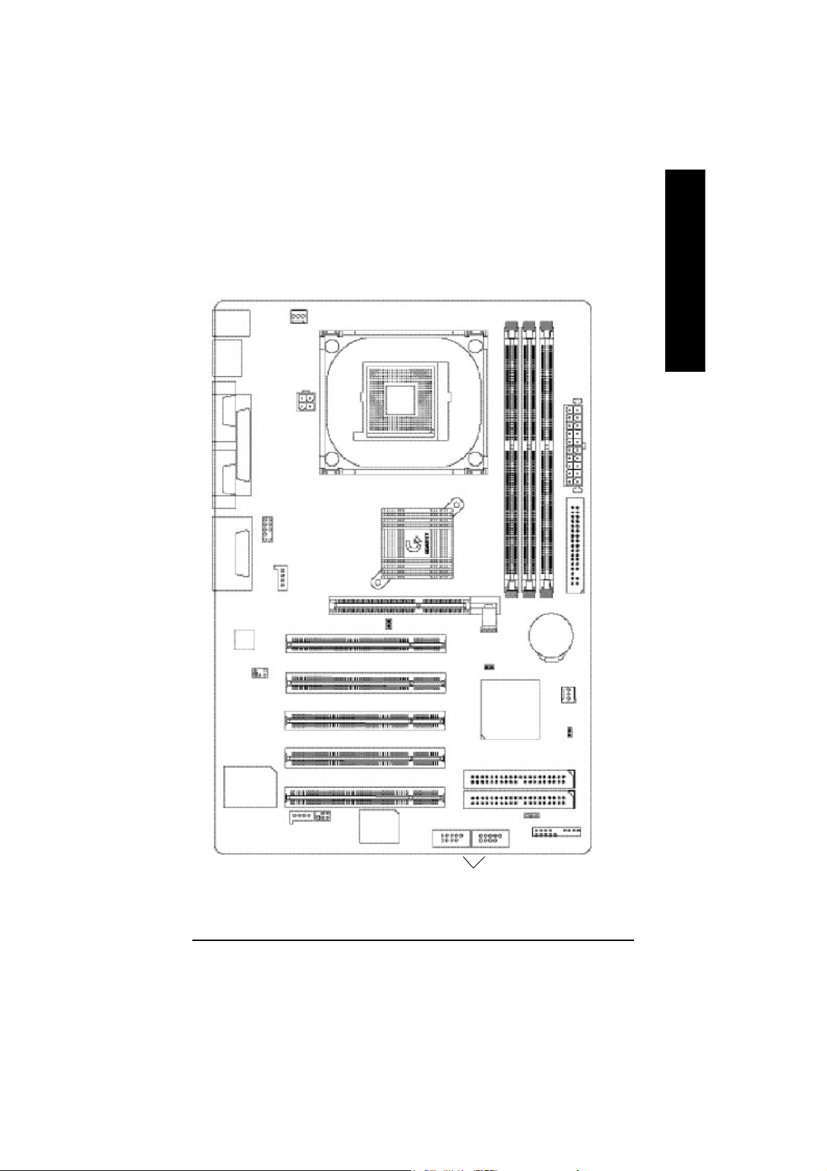
GA-8IE800 Motherboard Layout
English
KB_MS
USB
COMA
LINE_OUTMIC_IN
LINE_IN
COMB
AC 97
CPU_FAN
LPT1
GAME
SUR_CEN
ATX_12V
F_AUDIO
CD_IN
AGP
Intel 845E
P4 Titan
SOC KET4 78
2X_DET
PCI1
PCI2
PCI3
DDR1
GA-8IE800
CLR_PWD
ICH4
DDR2
DDR3
ATX
FLOPPY
BAT
SYS_FAN
CI
IT87 12
AUX_IN
SPDIF_IO
BIOS
PCI4
PCI5
F_USB1
Front USB 2.0
F_USB2
IDE2
IDE1
PWR_L ED
F_PANEL
Introduction- 7 -
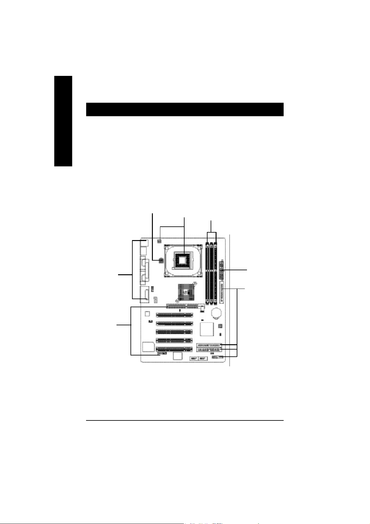
Chapter 2 Hardware Installation Process
To set up your computer, you must complete the following steps:
English
Step 1- Install the Central Processing Unit (CPU)
Step 2- Install memory modules
Step 3- Install expansion cards
Step 4- Connect ribbon cables, cabinet wires, and power supply
Step 5- Setup BIOS software
Step 6- Install supporting software tools
Step 4
Step3
Step4
Step1
Step 2
Step 4
Step 4
- 8 -GA-8IE800 M otherboard
Step 1: Install the Central Processing Unit (CPU)
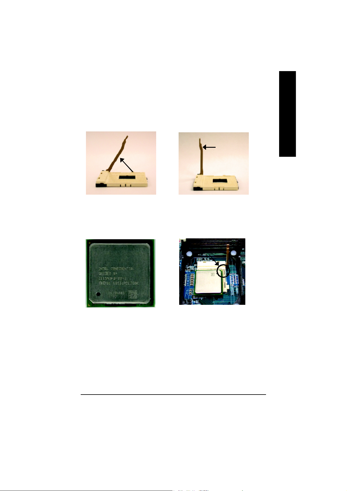
Step 1-1: CPU Installation
English
Angling the
rod to 65
1. Angling the rod to 65-degree maybe feel
a kind of tight , and then continue pull
the rod to 90-degree when a noise “cough”
made.
0
Pin1 indicator
3. CPU Top View
Socket
Actuation
Lever
2. Pull the rod to the 90-degree
directly.
Pin1 indicator
4. Locate Pin 1 in the socket and look
for a (golden) cut edge on the CPU
upper corner. Then insert the CPU
into the socket.
M Please make sure the CPU type is supported by the motherboard.
M If you do not match the CPU socket Pin 1 and CPU cut edge well, it will cause
improper installation. Please change the insert orientation.
- 9 - Hardware Installation Process

Step 1-2 : CPU Heat Sink Installation
English
1. Fasten the heatsink supporting-base
onto the CPU socket on the
mainboard.
M Please use Intel approved cooling fan.
M We recommend you to apply the thermal tape to provide better heat conduction between
your CPU and heatsink.
(The CPU cooling fan might stick to the CPU due to the hardening of the thermal paste.
During this condition if you try to remove the cooling fan, you might pull the processor out
of the CPU socket alone with the cooling fan, and might damage the processor. To avoid
this from happening, we suggest you to either use thermal tape instead of thermal paste, or
remove the cooling fan with extreme caution.)
M Make sure the CPU fan power cable is plugged in to the CPU fan connector, this completes
the installation.
M Please refer to CPU heat sink user’s manual for more detail installation procedure.
2. Make sure the CPU fan is plugged to
the CPU fan connector, than install
complete.
- 10 -GA-8IE800 Motherboard
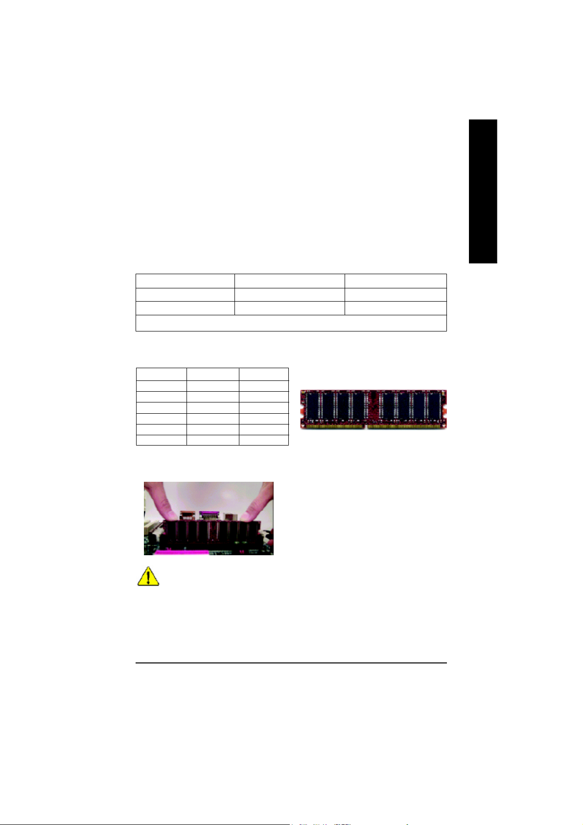
Step 2: Install memory modules
The motherboard has 3 dual inline memory module (DIMM) sockets, but it can only support a
maximum of 4 banks of DDR memory. DDR sockets 1 uses 2 banks, DDR sockets 2&3 share the
remaining 2 banks. Please refer to the following tables for possible memory configurations supported.
The BIOS will automatically detects memory type and size. To install the memory module, just push
it vertically into the DIMM socket .The DIMM module can only fit in one direction due to the notch.
Memory size can vary between sockets.
Support Unbuffered DDR DIMM Sizes type:
64 Mbit (2Mx8x4 banks) 64 Mbit (1Mx16x4 banks) 128 Mbit(4Mx8x4 banks)
128 Mbit(2Mx16x4 banks) 256 Mbit(8Mx8x4 banks) 256 Mbit(4Mx16x4 banks)
512 Mbit(16Mx8x4 banks) 512 Mbit(8Mx16x4 banks)
Total System Memory (Max2GB)
Install memory in any combination table:
DDR1 DDR2 DDR3
S S S
D S S
D D X
D X D
S D X
S X D
D:Double Sided DIMM S:Single Sided DIMM
X:Not Use
1. The DIMM socket has a notch, so the
DIMM memory module can only fit in one direction.
2. Insert the DIMM memory module vertically into the
DIMM socket. Then push it down.
3. Close the plastic clip at both edges of the DIMM
sockets to lock the DIMM module.
Reverse the installation steps when you wish to
remove the DIMM module.
DDR
English
M When DIMM LED is ON, do not install/remove DIMM from socket.
M Please note that the DIMM module can only fit in one direction due to
the one notches. Wrong orientation will cause improper installation.
Please change the insert orientation.
- 11 - Hardware Installation Process
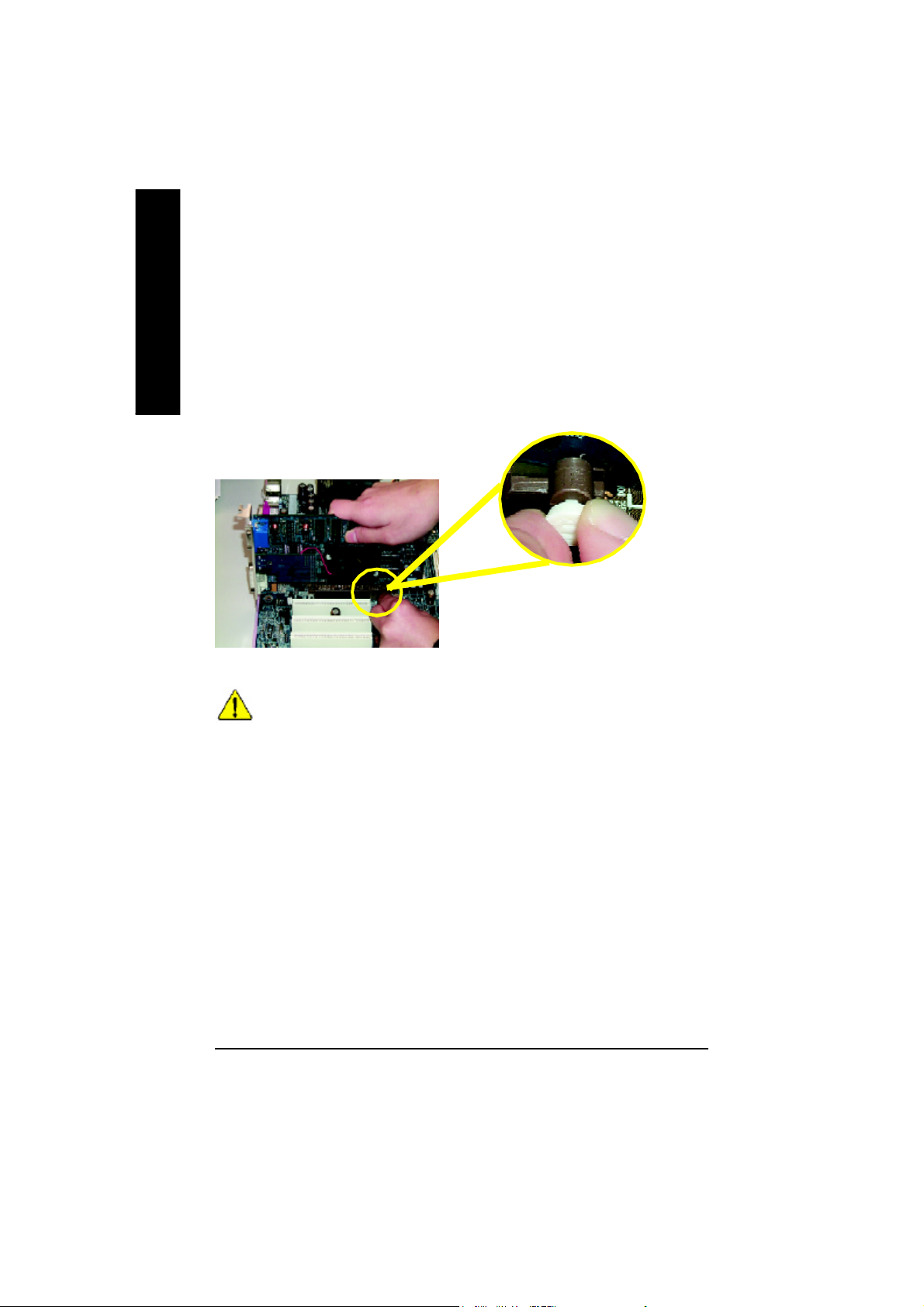
Step 3: Install expansion cards
1. Read the related expansion card’s instruction document before install the expansion card into
English
2. Remove your computer’s chassis cover, necessary screws and slot bracket from the computer.
3. Press the expansion card firmly into expansion slot in motherboard.
4. Be sure the metal contacts on the card are indeed seated in the slot.
5. Replace the screw to secure the slot bracket of the expansion card.
6. Replace your computer’s chassis cover.
7. Power on the computer, if necessary, setup BIOS utility of expansion card from BIOS.
8. Install related driver from the operating system.
DDR Introduction
Established on the existing SDRAM industry infrastructure, DDR (Double Data Rate) memory is a
high performance and cost-effective solution that allows easy adoption for memory vendors, OEMs
and system integrators.
DDR memory is a sensible evolutionary solution for the PC industry that builds on the existing
SDRAM infrastructure, yet makes awesome advances in solving the system performance bottleneck by doubling the memory bandwidth. DDR SDRAM will offer a superior solution and migration
path from existing SDRAM designs due to its availability, pricing and overall market support. PC2100
DDR memory (DDR266) doubles the data rate through reading and writing at both the rising and
falling edge of the clock, achieving data bandwidth 2X greater than PC133 when running with the
same DRAM clock frequency. With peak bandwidth of 2.664GB per second, DDR memory enables
system OEMs to build high performance and low latency DRAM subsystems that are suitable for
servers, workstations, high-end PC's and value desktop SMA systems. With a core voltage of only
2.5 Volts compared to conventional SDRAM's 3.3 volts, DDR memory is a compelling solution for
small form factor desktops and notebook applications.
the computer.
Please carefully pull out the small whitedrawable bar at the end of the AGP slot
when you try to install/ Uninstall the AGP
card. Please align the AGP card to the
onboard AGP slot and press firmly down on
AGP Card
When an AGP 2x (3.3V) card is installed the 2X_DET will light up, indicating a non-supported
graphics card is inserted. Informing users that system might not boot up normally due to AGP 2x
(3.3V) is not supported by the chipset.
the slot .Make sure your AGP card is locked
by the small white- drawable bar.
- 12 -GA-8IE800 Motherboard
Step 4: Connect ribbon cables, cabinet wires, and power
supply
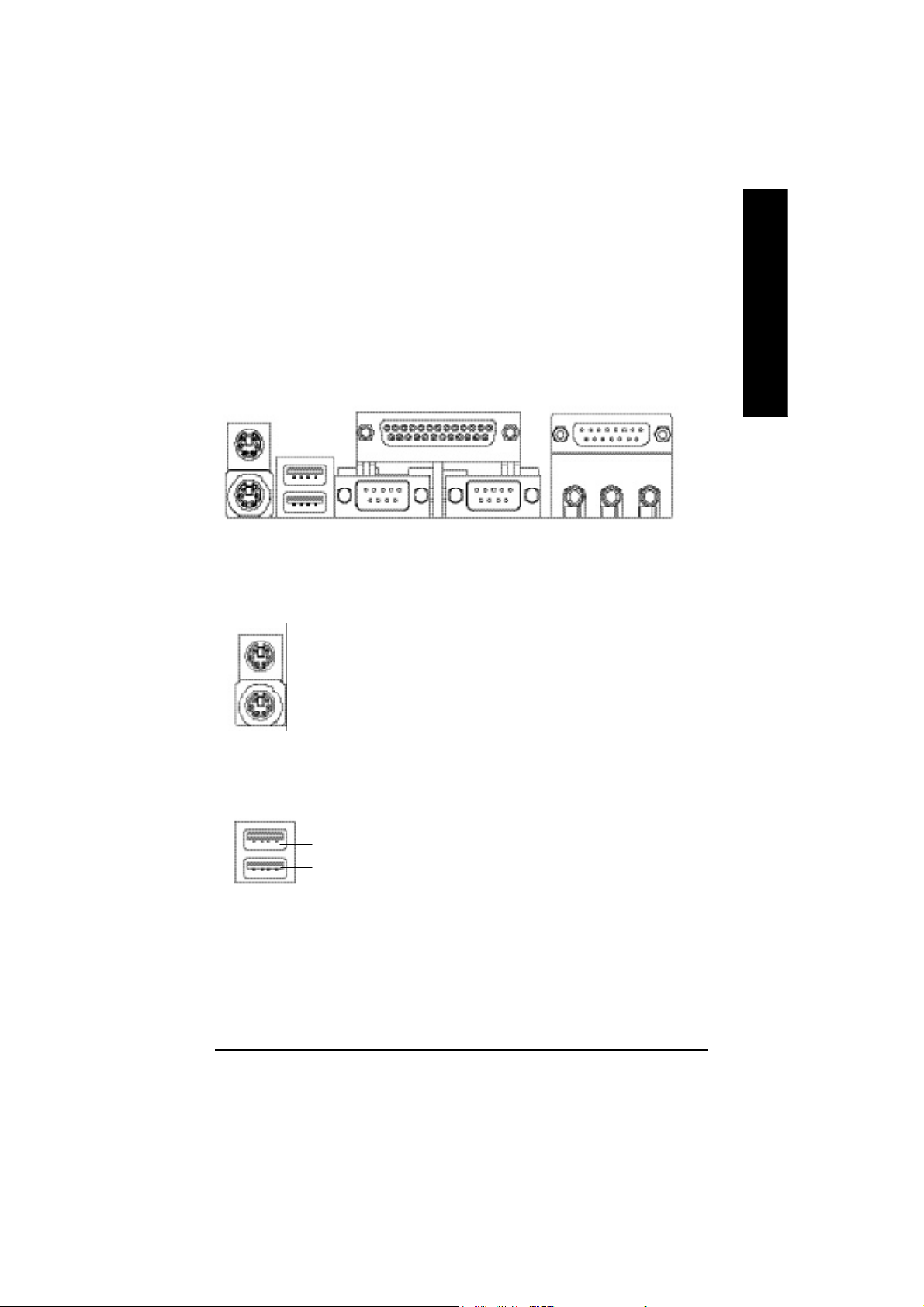
Step 4-1 : I/O Back Panel Introduction
English
u
v
w
u PS/2 Keyboard and PS/2 Mouse Connector
PS/2 Mouse Connector
(6 pin Female)
PS/2 Keyboard Connector
(6 pin Female)
v USB Connector
USB 1
USB 0
ØThis connector supports standard PS/2
Ø Before you connect your device(s) into USB
connector(s), please make sure your device(s)
such as USB keyboard, mouse, scanner, zip,
speaker..etc. Have a standard USB interface.
Also make sure your OS supports USB
controller. If your OS does not support USB
controller, please contact OS vendor for
possible patch or driver upgrade. For more
information please contact your OS or device(s)
vendors.
x
y
keyboard and PS/2 mouse.
- 13 - Hardware Installation Process
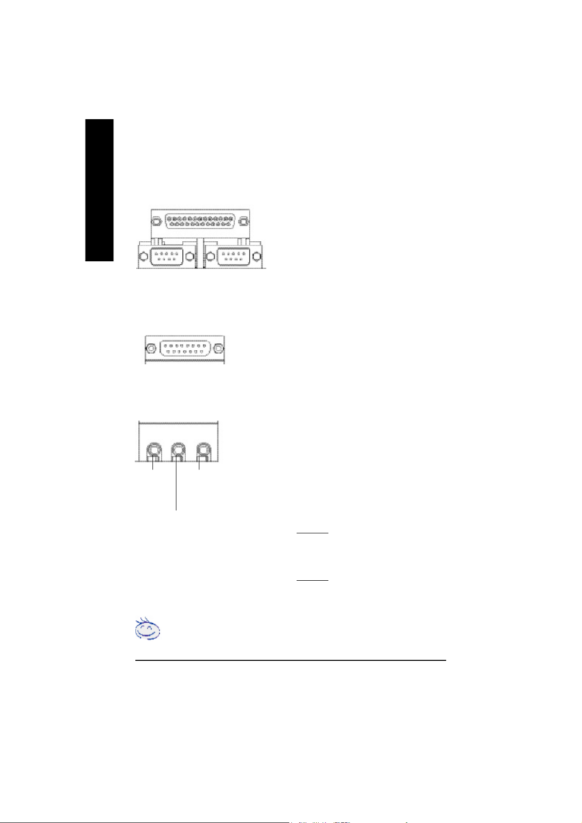
w Parallel Port ,VGA port and Serial Ports (COMA)
English
x Game /MIDI Ports
y Audio Connectors
Line Out
(Front
Speaker)
Parallel Port
(25 pin Female)
COMA
Serial Ports (9 pin Male)
Joystick/ MIDI (15 pin Female)
MIC In
(Center and Subwoofer)
Line In
(Rear Speaker)
COMB
Ø This connector supports 2 standard COM ports
and 1 Parallel port. Device like printer can be
connected to Parallel port ; mouse and modem
etc can be connected to Serial ports.
Ø This connector supports joystick, MIDI keyboard
and other relate audio devices.
Ø After install onboard audio driver, you may
connect speaker to Line Out jack, micro phone
to MIC In jack.
Device like CD-ROM , walkman etc can be
connected to Line-In jack.
Please note:
You are able to use 2-/4-/6- channel audio
feature by S/W selection.
If you want to enable 6-channel function, you
have 2 choose for hardware connection.
Method1:
Connect “Front Speaker” to “Line Out”
Connect “Rear Speaker” to “Line In”
Connect “Center and Subwooferr” to “MIC Out “.
Method2:
You can refer to page 21, and contact your
nearest dealerfor optional SUR_CEN cable.
If you want the detail information for 2-/4-/6-channel audio setup installation, please
refer to “2-/4-/6-Channel Audio Function Introduction”
- 14 -GA-8IE800 Motherboard
Step 4-2 :Connectors & Jumper Setting Introduction
1 3
4
English
15
13
12
7
1) CPU_FAN
2) SYS_FAN
3) ATX_12V
4) ATX Power
5) FDD
6) IDE1/IDE2
7) 2X_DET
8) PWR_LED
9) F_PANEL
14
11
10
8
10) F_USB1/F_USB2
11) SPDIF_IO
12) SUR_CEN
13) CD_IN
14) AUX_IN
15) F_AUDIO
16) CI
17) CLR_PWD
18) BAT
5
18
17
2
16
6
9
- 15 - Hardware Installation Process
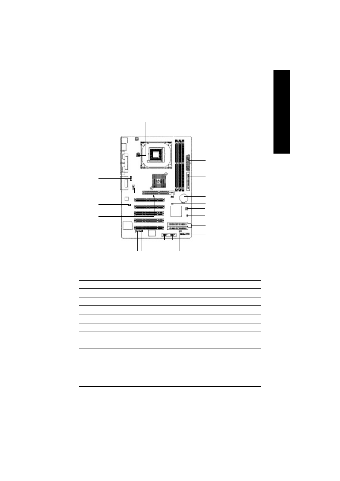
1) CPU_FAN (CPU FAN Connector)
English
2) SYS_FAN (System FAN Connector)
Please note, a proper installation of the CPU cooler is essential to prevent the CPU from running
under abnormal condition or dam aged by overheating.The CPU fan connector supports Max.
current up to 600 mA.
Pin No. Definition
1 GND
1
This connector allows you to link with the cooling fan on the system case to lower the system
temperature.
2 +12V
3 Sense
Pin No. Definition
1
- 16 -GA-8IE800 Motherboard
1 GND
2 +12V
3 Sense
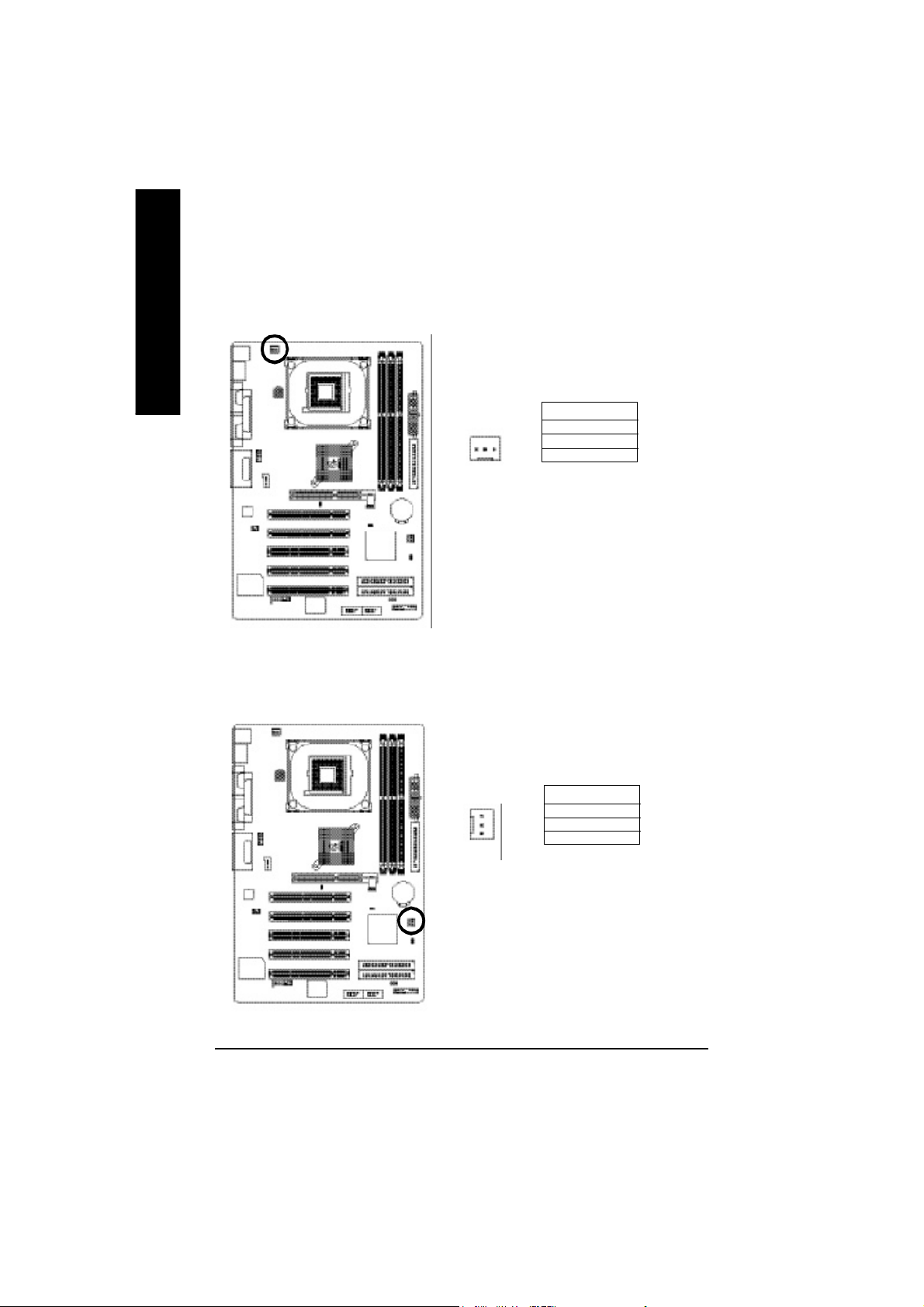
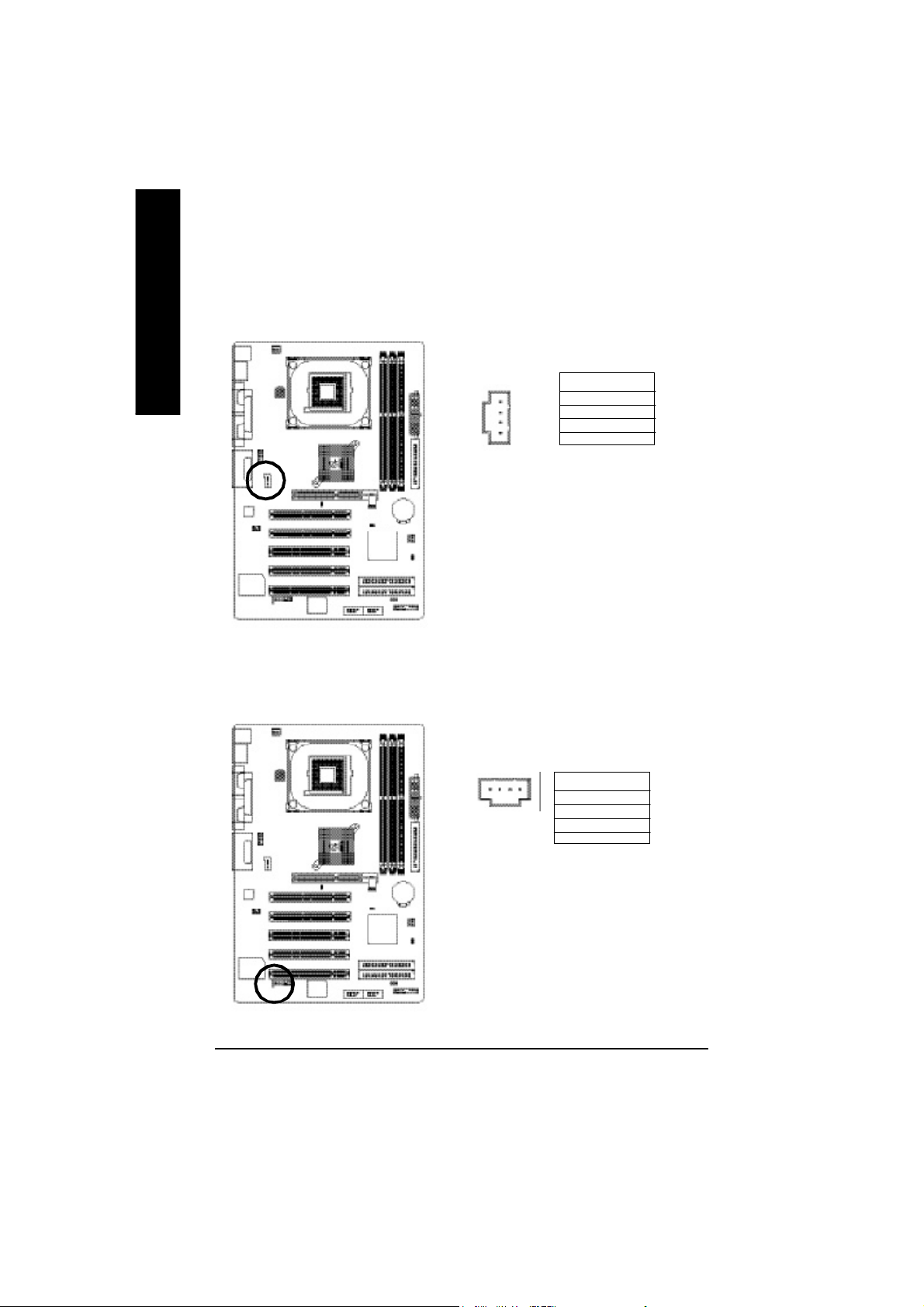
3) ATX_12V ( +12V Power Connector)
This connector (ATX _12V) suppliesthe CPU operation voltage (Vcore). If this " ATX_ 12V
connector" is not connected, system cannot boot.
English
3
1
4
2
Pin No. Definition
1 GND
2 GND
3 +12V
4 +12V
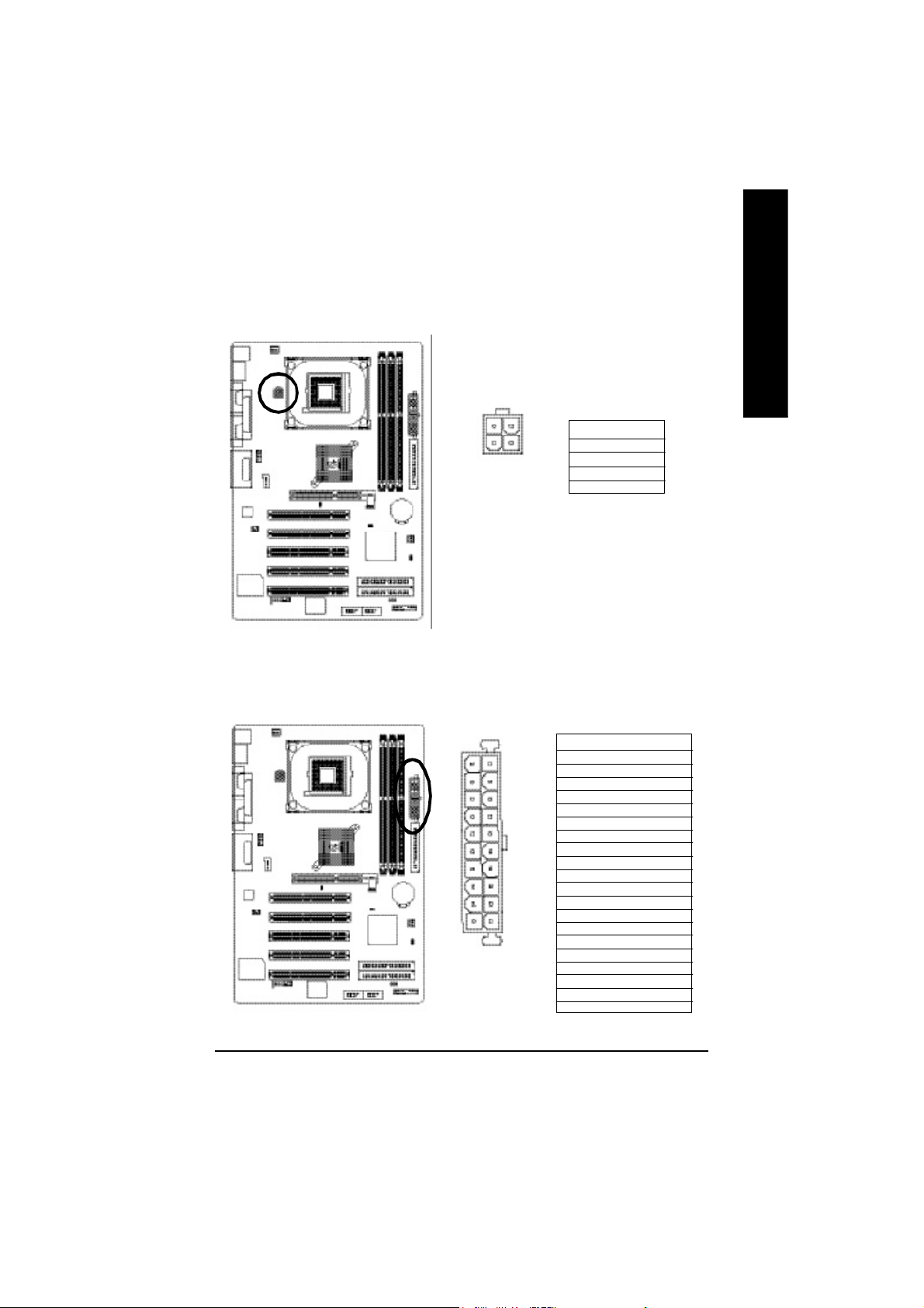
4) ATX_POWER (ATX Power)
AC power cord should only be connected to your power supply unit after ATX power cable and
other related devices are firmly connected to the mainboard.
Pin No. Definition
10
1 11
20
1 3.3V
2 3.3V
3 GND
4 VCC
5 GND
6 VCC
7 GND
8 Power Good
9 5V SB(s tand by +5 V)
10 +12V
11 3.3V
12 -12V
13 GND
14 PS_O N(softO n/Off)
15 GND
16 GND
17 GND
18 -5V
19 VCC
20 VCC
- 17 - Hardware Installation Process
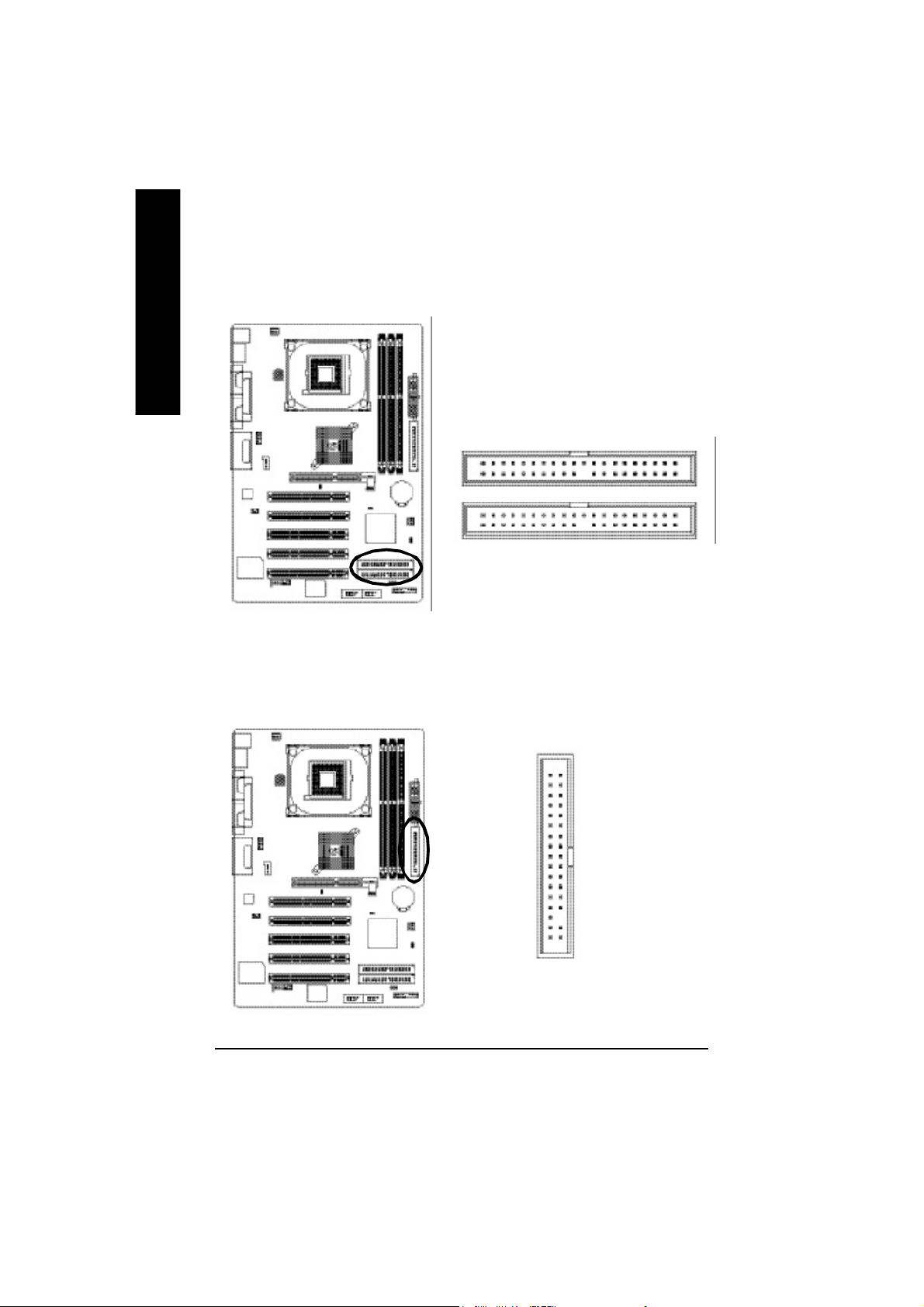
5) IDE1/ IDE2(IDE1/IDE2 Connector)
English
Please connect first harddisk to IDE1 and connect CDROM to IDE2. The red stripe of the ribbon
cable must be the sam e side with the Pin1.
2
IDE2
IDE1
1
6) FDD (Floppy Connector)
Please connect the floppy drive ribbon cables to FDD. It supports 360K,720K,1.2M,1.44M and
2.88Mbytes floppy disk types. The red stripe of the ribbon cable must be the same side with the
Pin1.
34
33
40
39
2
- 18 -GA-8IE800 Motherboard
1
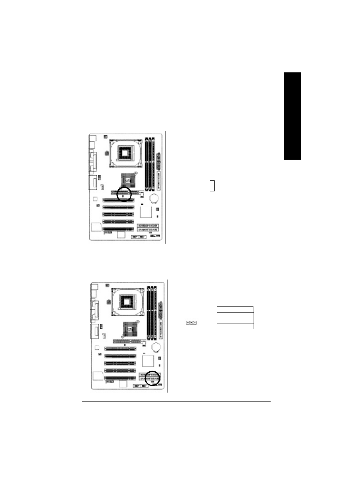
7)2X_DET
When an AGP 2X (3.3V) card is installed the 2X_DET will light up, indicating a
nonsupported g raphics card is inserted. Informing users that system might not boot
up normally due to AGP 2X (3.3V) is not supported by the chipset.
+
-
8) PWR_LED
PWR_LED is connect with the system power indicator to indicate whether the system is on/off. It
will blink when the system enters suspend mode. If you use dual color LED, power LED will turn
to another color.
English
Pin No. Definition
1 MPD+
1
- 19 - Hardware Installation Process
2 MPD3 MPD-
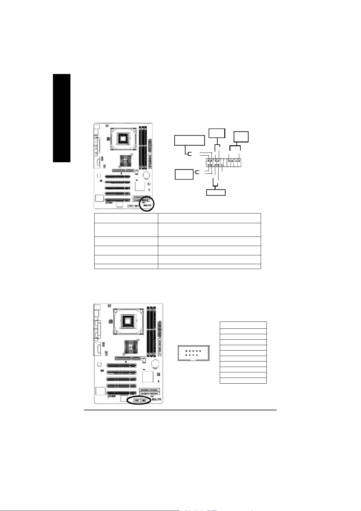
9) F_PANEL (2x10 pins connector)
Please connect the power LED, PC peaker, reset switch and power switch etc of your
chassis front panel to the F_PANEL connector according to the pin assignment above.
English
10)F_ USB1 / F_USB2(Front USB Connector, Yellow )
Mes sa ge LE D/ Po wer /
Sleep LED
MPDMPD+
1
IDE H ard Disk
Activ e LED
HD (I DE Hard Di sk Active LED) Pi n 1: LED an ode(+)
(Blu e) Pin 2: LED cath ode(-)
SPK (S peaker Connector) Pin 1: VCC (+)
(Amb er) Pin 2- Pin 3: N C
RES (Rese t Switch) Op en: N ormal Operation
(Gre en) Clo se: Reset Hardw are Sys tem
PW (Soft Po wer Conn ector) Open: Norma l O peration
(Re d) Clos e: Power On/ Off
MSG( Message LED/Power/ Pi n 1: LED anode( +)
Sleep LED)(Yellow ) Pin 2: LED cathode( -)
NC ( Purple) NC
Pin 4: Data(-)
HD+
HD-
Soft Po wer
Connector
PW+
1
1
1
RSE-
RSE +
Reset Swi tch
PW-
Speaker
Connector
SPK -
SPK +
202
1
1
NC
19
Be careful with the polarity of the front USB connector. Check the pin assignment while you
connect the front USB cable. Please contact your nearest dealer for optional front USB cable.
- 20 -GA-8IE800 Motherboard
2910
1
Pin No. Definition
1 Power
2 Power
3 USB DX4 USB Dy5 USB DX+
6 USB Dy+
7 GND
8 GND
9 No Pin
10 NC
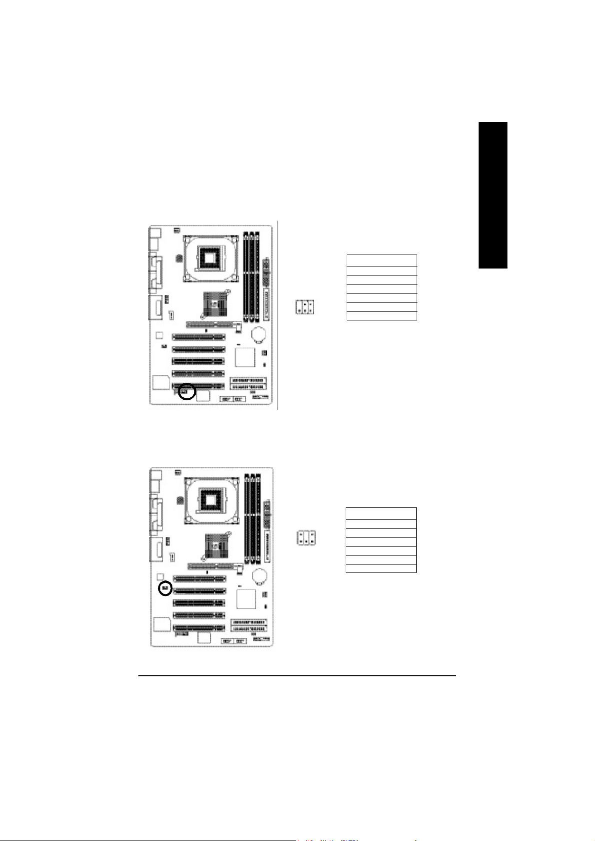
11) SPDIF_IO (SPDIF In/Out)
The SPDIF output is capable of providing digital audio to external speakers or compressed AC3
data to an external Dolby Digital Decoder. Use this feature only when your stereo system has
digital input function.
Use SPDIF IN feature only when your device has digital output function.
Pin No. Definition
1 VCC
2 No Pin
2
6
1
5
3 SPDIF
4 SPDIFI
5 GND
6 GND
12) SUR_CEN
Please contact your nearest dealer for optional SUR_CEN cable.
English
Pin No. Definition
2
6
5
1
- 21 - Hardware Installation Process
1 SUR OUTL
2 SUR OUTR
3 GND
4 No Pin
5 CENTER_OUT
6 BASS_OUT
13) CD_IN (CD IN,Blank)
English
14) AUX_IN ( AUX In Connector)
Connect CD-ROM or DVD-ROM audio out to the connector.
1
Connect other device(such as PCI TV Tunner audio out)to the connector.
Pin No. Definition
1 CD-L
2 GND
3 GND
4 CD_R
Pin No. Definiti on
1 AUX-L
1
- 22 -GA-8IE800 Motherboard
2 GND
3 GND
4 AUX_R

15) F_AUDIO (F_AUDIO Connector)
If you want to use Front Audio connector, you must remove 5-6, 9-10 Jum per. In order to utilize the
front audio header, your chassis must have front audio connector. Also please make sure the pin
assigment on the cable is the sam e as the pin assigm ent on the M B header. To find out if the chassis
you are buying support front audio connector, please contact your dealer.
Pin No. Definition
1 MIC
2 GND
3 REF
4 POWER
5 FrontAudio(R)
6 RearAudio(R)
7 Reserved
8 No Pi n
9 FrontAudio (L)
10 RearAudio(L)
10
2
1
9
16) CI (CASE OPEN)
This 2 pin connector allows your system to enable or disable the “case open” item in BIOS
if the system case begin remove.
English
Pin No. Definition
1 Signal
1
2 GND
- 23 - Hardware Installation Process
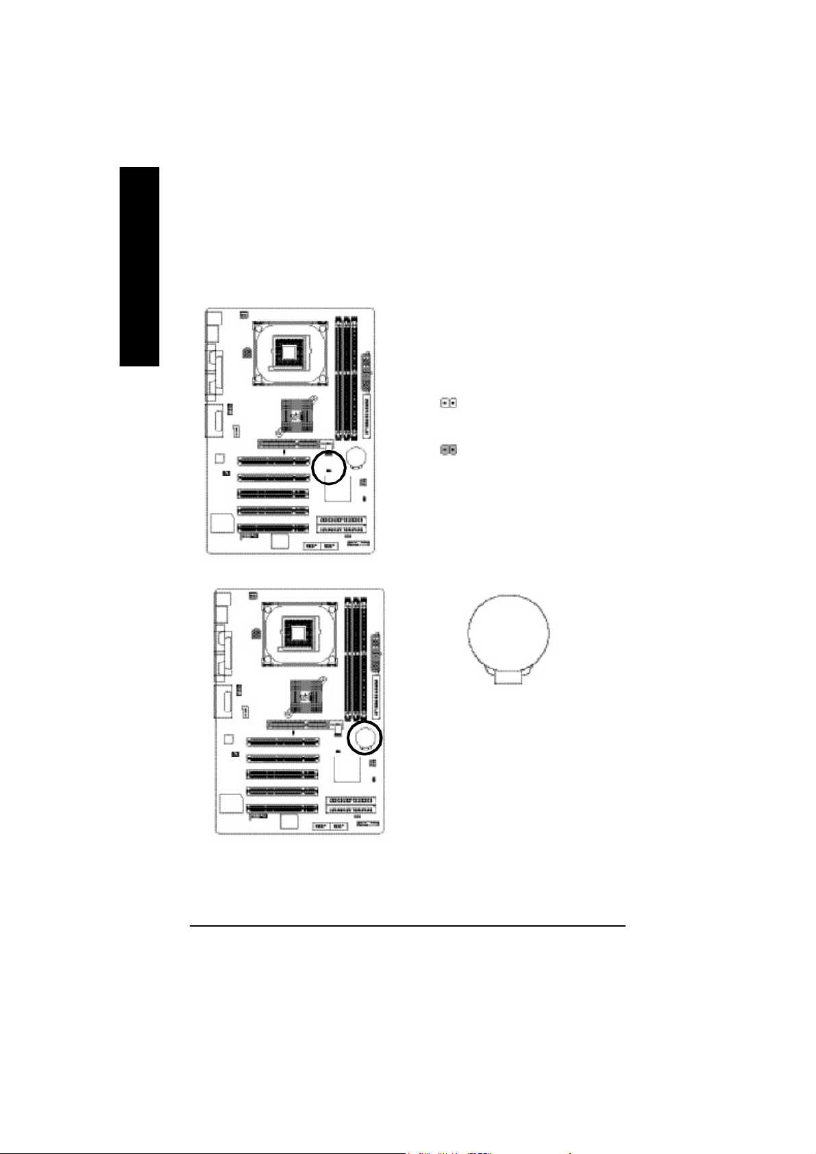
17) CLR_PWD
On the contrary when Jumper is set to "close", the current status remains
English
M PS, the function offers a solution for users who forget the password.
18) BATTERY (Battery)
When Jumper is set to "open" and system is restarted, the password that is set will be cleared.
1
open: Clear password
close: Normal
1
v Danger of explosion if battery is incorrectly
replaced.
v Replace only with the same or equivalent
type recommended by the manufacturer.
v Dispose of used batteries according to the
manufacturer’s instructions.
If you want to erase CMOS...
1.Turn OFF the computer and unplug the power cord.
2.Remove the battery, wait for 30 second.
3.Re-install the battery.
4.Plug the power cord and turn ON the computer.
- 24 -GA-8IE800 Motherboard
+
CAUTION

Chapter 3 BIOS Setup
BIOS Setup is an overview of the BIOS Setup Program. The program that allows users to modify
the basic system configuration. This type of information is stored in battery-backed CMOS RAM so
that it retains the Setup information when the power is turned off.
ENTERING SETUP
After power on the computer, pressing <Del> immediately during POST (Power On Self Test) it will allow you to
enter standard BIOS CMOS SETUP.
If you require more advanced BIOS settings, please go to “advanced BIOS” setting menu.To enter
Advanced BIOS setting menu, press “Ctrl+F1” key on the BIOS screen.
CONTROL KEYS
<á> Move to previous item
<â> Move to next item
<ß> Move to the item in the left hand
<à> Move to the item in the right hand
<Esc> Main Menu - Quit and not save changes into CMOS Status Page Setup Menu and
Option Page Setup Menu - Exit current page and return to Main Menu
<+/PgUp> Increase the numeric value or make changes
<-/PgDn> Decrease the numeric value or make changes
<F1> General help, only for Status Page Setup Menu and Option Page Setup Menu
<F2> Item help
<F3> Reserved
<F4> Reserved
<F5> Restore the previous CMOS value from CMOS, only for Option Page Setup Menu
<F6> Load the default CMOS value from BIOS default table, only for Option Page Setup
Menu
<F7> Load the Setup Defaults
<F8> Q-Flash
<F9> Reserved
<F10> Save all the CMOS changes, only for Main Menu
English
- 25 -
BIOS Setup
 Loading...