

Page 1

GA-8GEM 800
Intel® Pentium
User's Manual
Rev. 1001
12ME-8GEM800-1001
®
4 Socket 478 Proc essor Motherboard
Page 2

Sept. 1, 2004
GA-8GEM800
Motherboard
Sept. 1, 2004
Motherboard
GA-8GEM800
Page 3

Copyright
© 2004 G IGA-BYTE TECHNOLOGY CO., LTD. All rights reserved.
The trademarks mentioned in the manual are legally registered to their respective companies.
Notice
The written content provided with this product is the property of Gigabyte.
No part of this manual may be reproduced, copied, translated, or transmi tted in any form or by any
means without G igabyte's prior written permission. Specifications and features are subject to
change without prior notice.
Product Manual Classification
In order to assist in the use of this product, Gigabyte has categorized the user manual in the
following:
n For quick instal lation, please refer to the "Hardware Installation Guide" included with the
product.
n For detailed product i nformation and specifications, please carefully read the
"Product User Manual".
n For detailed information rel ated to Gigabyte's unique features, please go to Gigabyte's
website under "Technology Guide" where information can be downloaded in .pdf format.
Fore more product details, please click onto Gigabyte's website at www.gigabyte.com.tw
Page 4

Tab le of Contents
GA-8GEM800 Motherboard Layout .............................................................................6
Block Diagram ...........................................................................................................7
Chapter 1 Hardware Installation..................................................................................9
1-1 Considerations Prior to Installation .........................................................................9
1-2 Feature Summary .................................................................................................10
1-3 Installation of the CPU and Heatsink...................................................................12
1-3-1 Installation of the CPU ....................................................................................12
1-3-2 Installation of the Heatsink ..............................................................................13
1-4 Installation of Memory...........................................................................................14
1-5 Installation of Expansion Cards ...........................................................................16
1-6 I/O Back Panel Introduction .................................................................................17
1-7 Connectors Introduction ........................................................................................18
Chapter 2 BIOS Setup ............................................................................................29
The Main Menu (F or example: BIOS Ver. : E2)............................................................30
2-1 Standard CMOS Features ...................................................................................32
2-2 Advanced BIOS Features....................................................................................34
2-3 Integrated Peripherals ...........................................................................................36
2-4 Power Management Setup...................................................................................39
2-5 PnP/PCI Configurations.......................................................................................41
2-6 PC Health Status ..................................................................................................42
2-7 Frequency/V oltage Control ...................................................................................43
2-8 Top Performance....................................................................................................44
2-9 Load Fail-Safe Defaults .........................................................................................45
2-10 Load Optimized Defaults .......................................................................................45
2-11 Set Supervisor/User Password ..........................................................................46
2-12 Save & Exit Setup ...............................................................................................47
2-13 Exit Without Saving ..............................................................................................47
Chapter 3 Driver s Installation ...................................................................................49
3-1 Install Chipset Drivers ..........................................................................................49
3-2 Software Applications............................................................................................50
3-3 Driver CD Information ...........................................................................................50
3-4 Hardware Information ...........................................................................................51
3-5 Contact Us ............................................................................................................51
- 4 -
Page 5

Chapter 4 Appendix ...............................................................................................53
4-1 Unique Software Util ity .........................................................................................53
4-1-1 Xpres s Recovery Introduction .......................................................................53
4-1-2 BIOS Flash Method Introduction ....................................................................56
4-1-3 2 / 4 / 6 Channel Audio Function Introduction ...............................................65
4-2 Troubleshooting ......................................................................................................71
- 5 -
Page 6
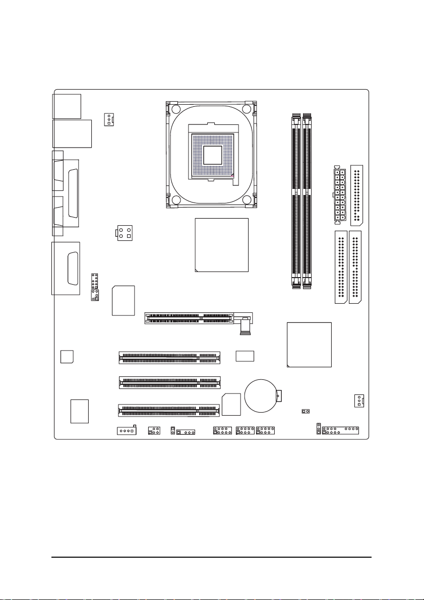
GA-8GEM800 Motherboard Layout
KB_MS
CPU_FAN
LAN
USB
COMA
SOCKET478
LPT
VGA
ATX_12V
Intel 845GE
GA-8GEM800
ATX
FDD
LINE_OUTMIC_IN
LINE_IN
CODEC
GAME
RTL
8100C
F_AUDIO
IT8712
SUR_CEN
CD_IN
SPDIF_IO
DDR1
AGP
PCI1
PCI2
F_USB1
BAT
F_USB2
55
PCI3
BIOS
CI
IR
COMB
DDR2
ICH4
CLR_CMOS
PWR_LED
IDE2 IDE1
SYS _FAN
F_PANEL
- 6 -
Page 7
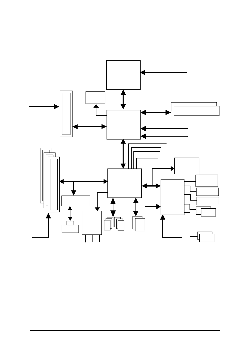
Block Diagram
AGPCLK
(66MHz)
3 PC I
PC ICLK
(33MHz)
AGP 4X
RT L8100C
RJ 45
VGA Port
AC97 Link
AC 97
COD EC
MIC
LINE-IN
Pentium 4
Soc ket 478
Intel 82845GE
Intel ICH4
6 USB
Ports
(2.0/1.1)
LINE-OUT
CPU
Sy stem Bus
400/533MHz
200/266/ 333MHz
48 MHz
LPC BUS
24 MHz
ATA33/66/100
IDE Channels
CPU CLK+/- (100/133MHz)
DDR
66M Hz
HCLK+/ - (100/133MHz)
66M Hz
33 MHz
14. 318 MHz
BIOS
IT8712
33 MHz
Gam e Port
Floppy
LPT Port
PS/2
KB/Mouse
COM
Port s
- 7 -
Page 8

- 8 -
Page 9

Chapter 1 Hardware Installation
1-1 Considerations Prior to Installation
Preparing Y our Computer
The motherboard contains numerous delicate electronic circuits and components which can
become damaged as a result of electrostatic discharge (ESD). Thus, prior to installation, please
follow the instructions below:
1. Please turn off the computer and unplug its power cord.
2. When handling the motherboard, avoid touching any metal leads or connectors.
3. It is best to wear an electrostatic discharge (ESD) cuff when handling electronic components
(CPU, RAM).
4. Prior to installing the electronic components, please have these items on top of an antistatic pad or
within a electrostatic shielding container.
5. Please verify that you the power supply is switched off before unplugging the power supply connector
from the motherboard.
Installation Notices
1. Prior to installation, please do not remove the stickers on the motherboard. These stickers are required
for warranty validation.
2. Prior to the installation of the motherboard or any hardware, please first carefully read theinformation
in the provided manual.
3. Before using the product, please verify that all cables and power connectors are connected.
4. To prevent damage to the motherboard, please do not allow screws to come in contact with the
motherboard circuit or its components.
5. Please make sure there are no leftover screws or metal components placed on the motherboard or
within the computer casing.
6. Please do not place the computer system on an uneven surface.
7. Turning on the computer power during the installation process can lead to damage to system
components as well as physical harm to the user.
8. If you are uncertain about any installation steps or have a problem related to the use of the product,
please consult a certified computer technician.
English
Instances of Non-Warranty
1. Damage due to natural disaster, accident or human cause.
2. Damage as a result of violating the conditions recommended in the user manual.
3. Damage due to improper installation.
4. Damage due to use of uncertified components.
5. Damage due to use exceeding the permitted parameters.
6. Product determined to be an unofficial Gigabyte product.
Hardware Installation- 9 -
Page 10

English
1- 2 Feature Summary
CPU Socket 478 for Intel® Pentium® 4 (Northwood, Prescott) processor with
HT Technology
Supports 400/533MHz FSB
L2 cache varies with processors
Chipset Northbridge:Intel® 845GE
Southbridge: Intel® ICH4
Memory 2 184-pin DDR DIMM sockets
Supports DDR333/DDR266/DDR200 DIMM
Supports up to 2GB DRAM (Max.)
Supports only 2.5V DDR DIMM
Slots 1 AGP slot 4X (1.5V) device support
3 PCI slot supports 33MHz & PCI 2.2 compliant
IDE Connections 2 IDE connection (UDMA 33/ATA 66/ATA 100), allows connection of 4
IDE devices
FDD Connections 1 FDD connection, allows connection of 2 FDD devices
Peripherals 1 parallel port supporting Normal/EPP/ECP mode
1 VGA port, 1 COMA port, onboard COMB connection
6 USB 2.0/1.1 ports (2 x rear, 4 x front by cable)
1 Front Audio Connector
1 IrDA connector for IR
1 PS/2 keyboard port
1 PS/2 mouse port
Onboard VGA Built-in Intel® 845GE Chipset
Onboard LAN Built-in RTL8100C chip
1 RJ45 port
Onboard Audio Realtek ALC655 CODEC
Supports Line In ; Line Out ; MIC In
Supports 2 / 4 / 6 channel audio
Supports SPDIF In/Out connection
CD In/ Game port
I/O Control IT8712
(note 1)
(Note 1) Due to (Intel 845PE/GE/GV) chipset architecture limitation, DDR333 memory modules are
supported only when you install a Pentium 4 processor with 533MHz FSB.
A Pentium 4 processor with 400MHz FSB will support DDR200/266 memory modules.
GA-8GEM800 Motherboard - 10 -
Page 11

Hardware Monitor CPU / System fan speed detection
CPU overheating warning
System voltage detection
CPU / System fan failure warning
BIOS Use of licensed AWARD BIOS
Supports Q-Flash
Additional Features Supports @BIOS
Supports EasyTune
Overclocking Over Clock via BIOS (CPU/DDR/AGP)
Form Factor Micro-ATX form factor; 24.4cm x 22cm
English
Hardware Installation- 11 -
Page 12

1-3 Installation of the CPU and Heatsink
English
Before installing the CPU, please comply with the following conditions:
1. Please make sure that the motherboard supports the CPU.
2. Please take note of the pin one marks on the processor and socket. If you install the
CPU in the wrong direction, the CPU will not insert properly. If this occurs, please
change the insert direction of the CPU.
3. Please add an even layer of heat sink paste between the CPU and heatsink.
4. Please make sure the heatsink is installed on the CPU prior to system use, otherwise
overheating and permanent damage of the CPU may occur.
5. Please set the CPU host frequency in accordance with the processor specifications. It is not
recommended that the system bus frequency be set beyond hardware specifications since it
does not meet the required standards for the peripherals. If you wish to set the frequency
beyond the proper specifications, please do so according to your hardware specifications
including the CPU, graphics card, memory, hard drive, etc.
HT functionality requirement content :
Enabling the functionality of Hyper-Threading Technology for your computer system requires all
of the following platform components:
- CPU: An Intel® Pentium 4 Processor with HT Technology
- Chipset: An Intel® Chipset that supports HT Technology
- BIOS: A BIOS that supports HT Technology and has it enabled
- OS: An operation system that has optimizations for HT Technology
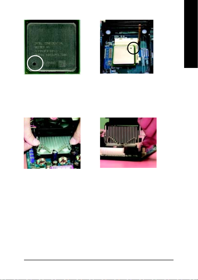
1-3-1 Installation of the CPU
Raise the processor
socket handle to 65
degrees.
Fully raise the processor socket handle.
1. Raise the processor socket handle to
65 degrees. You maybe feel a kind of
tight.
GA-8GEM800 Motherboard - 12 -
2. Raise the processor socket
handle all the way up to a fully
raised position (around 90
degrees) till you hear a "click."
Page 13
Pin OnePin One
Pin One
Pin OnePin One
IndicatorIndicator
Indicator
IndicatorIndicator
English
3. Locate the Pin One Indicator on the
processor.
4. Locate Pin One in the socket and
look for a (golden) cut edge on the
CPU upper corner. Then insert the
CPU into the socket and close the
socket handle.
1-3-2 Installation of the Heatsink
1. Push down the cooler clip to secure to the
retention mechanism hooks for all four corners.
00
0 Please use Intel® approved cooling fan.
00
00
0 We recommend you to apply the thermal tape to provide better heat conduc
00
tion between your CPU and heatsink. (The CPU cooling fan might stick to the
CPU due to the hardening of the thermal paste. During this condition if you
try to remove the cooling fan, you might pull the processor out of the
CPU socket alone with the cooling fan, and might damage the processor. To
avoid this from happening, we suggest you to either use thermal tape in
stead of thermal paste, or remove the cooling fan with extreme caution.)
00
0 Make sure the CPU fan power cable is plugged in to the CPU fan connector,
00
this completes the installation.
00
0 Please refer to CPU heat sink user’s manual for more detail installation
00
procedure.
2. Plug the cooler power cable into the CPU fan
connector on the motherboard.
Hardware Installation- 13 -
Page 14
English
1-4 Installation of Memory
Before installing the memory modules, please comply with the following conditions:
1. Please make sure that the memory used is supported by the motherboard. It is recommended that
memory of similar capacity, specifications and brand be used.
2. Before installing or removing memory modules, please make sure that the computer
power is switched off to prevent hardware damage.
3. Memory modules have a foolproof insertion design. A memory module can be
installed in only one direction. If you are unable to insert the module, please switch the
direction.
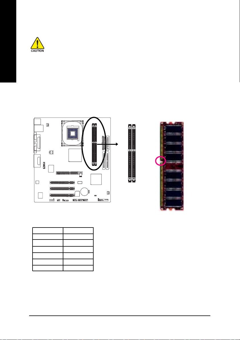
The motherboard has 2 dual inline memory module (DIMM) sockets. The BIOS will automatically
detects memory type and size. To install the memory module, just push it vertically into the DIMM
socket. The DIMM module can only fit in one direction due to the notch. Memory size can vary between
sockets.
notch
55
DDR1 DDR2
SS
DS
DD
DX
SD
SX
D:Double Sided DIMM S:Single Sided DIMM
X:Not Use
GA-8GEM800 Motherboard - 14 -
DDR memory module
Page 15
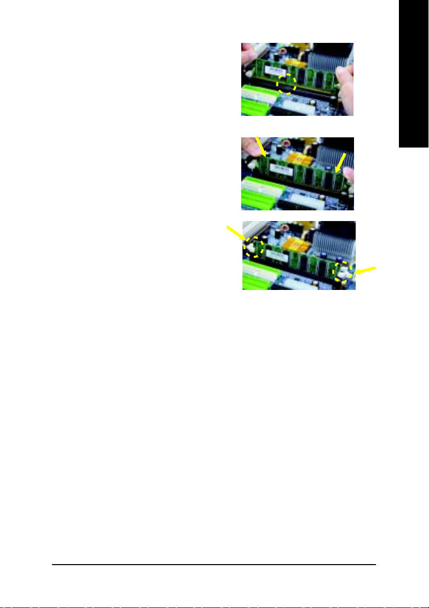
1. The DIMM slot has a notch, so the DIMM
memory module can only fit in one direction.
2. Insert the DIMM memory module vertically
into the DIMM slot. Then push it down.
3. Close the plastic clip at both edges of the DIMM
slots to lock the DIMM module.
Reverse the installation steps when you wish
to remove the DIMM module.
English
Hardware Installation- 15 -
Page 16
English
1- 5 Installation of Expansion Cards
You can install your expansion card by following the steps outlined below:
1. Read the related expansion card's instruction document before installing the expansion card into
the computer.
2. Remove your computer's chassis cover, screws and slot bracket from the computer.
3. Press the expansion card firmly into expansion slot in motherboard.
4. Be sure the metal contacts on the card are indeed seated in the slot.
5. Replace the screw to secure the slot bracket of the expansion card.
6. Replace your computer's chassis cover.
7. Power on the computer, if necessary, setup BIOS utility of expansion card from BIOS.
8. Install related driver from the operating system.
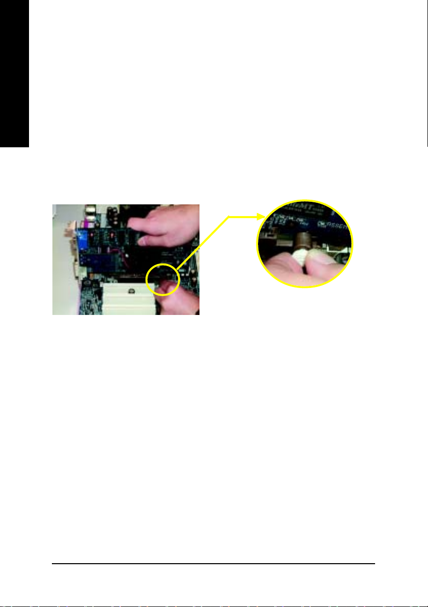
Installing an AGP expansion card:
Please carefully pull out the small white-drawable
bar at the end of the AGP slot when you try to
AGP Card
install/uninstall the VGA card. Please align the VGA
card to the onboard AGP slot and press firmly
down on the slot. Make sure your VGA card is
locked by the small white-drawable bar.
GA-8GEM800 Motherboard - 16 -
Page 17
1-6 I/O Back Panel Introduction
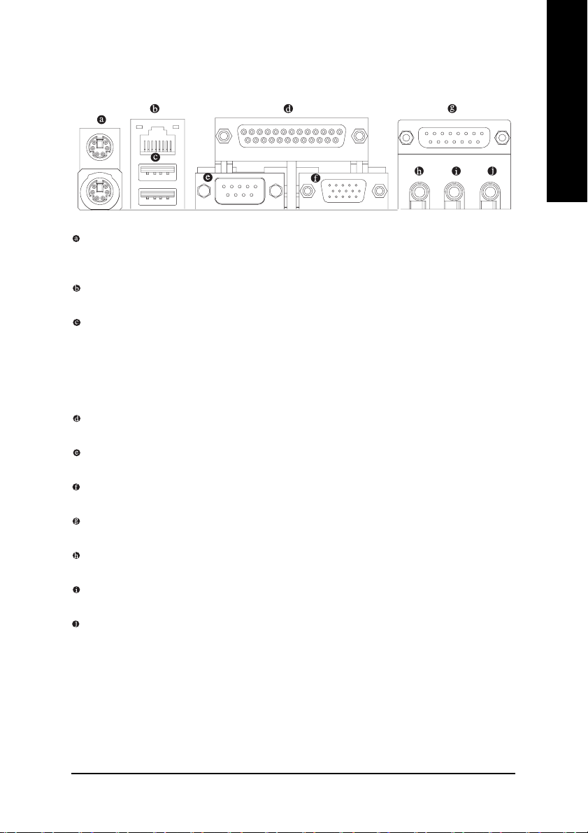
PS/2 Keyboard and PS/2 Mouse Connector
T o install a PS/2 port keyboard and mouse, plug the mouse to the upper port (green) and the keyboard to the
lower port (purple).
LAN Port
The LAN port provides Internet connection.
USB port
Before you connect your device(s) into USB connector(s), please make sure your device(s) such
as USB keyboard, mouse, scanner, zip, speaker...etc. have a standard USB interface. Also make
sure your OS supports USB controller. If your OS does not support USB controller, please contact OS vendor for possible patch or driver upgrade. For more information please contact your
OS or device(s) vendors.
Parallel Port
The parallel port allows connection of a printer, scanner and other peripheral devices.
Serial Port
Devices like mouses, modems, and etc. can be connected to Serial port.
VGA Port
Monitor can be connected to VGA port.
Game/MIDI Port
This connector supports joystick, MIDI keyboard and other related audio devices.
Line Out (Front Speaker Out)
Connect the stereo speakers, earphone or front surround channels to this connector.
Line In
Devices like CD-ROM, walkman etc. can be connected to Line In jack.
MIC In
Microphone can be connected to MIC In jack.
English
Hardware Installation- 17 -
Page 18

English
1- 7 Connectors Introduction
3
1
8
9
14
4
6
5
18
2
55
17
10
11 1315
12
16
7
1) CPU_FAN 10) F_PANEL
2) SYS_FAN 11) CD_IN
3) ATX_12V 12) SPDIF_IO
4) ATX 13) F_USB1/F_USB2
5) IDE1/IDE2 14) C I
6) FDD 15) I R
7) PWR_LED 16) COMB
8) F_AUDIO 17) CLR_CMOS
9) SUR_CEN 18) BAT
GA-8GEM800 Motherboard - 18 -
Page 19

1/2) CPU_FAN / SYS_FAN (CPU Fan Connector/System Fan Connector)
Please note, a proper installation of the CPU cooler is essential to prevent the CPU from running
under abnormal condition or damaged by overheating. The CPU fan connector supports max.
current up to 600 mA.
SYS_FAN connector allows you to link with the cooling fan on the system case to lower
the system temperature.
Pin No. Definition
1 GND
1
CPU_FAN
55
1
SYS_FAN
2 +12V
3 Sense
Pin No. Definition
1 GND
2 +12V
3 Sense
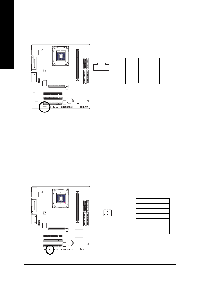
3) ATX_12V (+12V Power Connector)
The ATX_12V power connector mainly supplies power to the CPU. If the ATX_12V power
connector is not connected, the system will not start.
English
4
3
55
2
1
Pin No. Definition
1GND
2GND
3 +12V
4 +12V
Hardware Installation- 19 -
Page 20
English
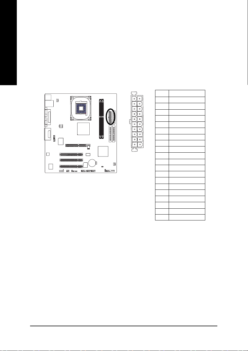
4) ATX (ATX Power)
With the use of the power connector, the power supply can supply enough stable power to all
the components on the motherboard. Before connecting the power connector, please make sure
that all components and devices are properly installed. Align the power connector with its
proper location on the motherboard and connect tightly.
Please use a power supply that is able to handle the system voltage requirements. It is
recommended that a power supply that can withstand high power consumption be used (300W
or greater). If a power supply that does not provide the required power is used, the result can
lead to an unstable system or a system that is unable to start.
Pin No. Definition
11
20
55
1
1 3.3V
2 3.3V
3 GND
4 VCC
5 GND
6 VCC
7 GND
8 Power Good
10
9 5V SB (stand by +5V)
10 +12V
11 3.3V
12 -12V
13 GND
14 PS_ON (soft on/off)
15 GND
16 GND
17 GND
18 -5V
19 VCC
20 VCC
GA-8GEM800 Motherboard - 20 -
Page 21
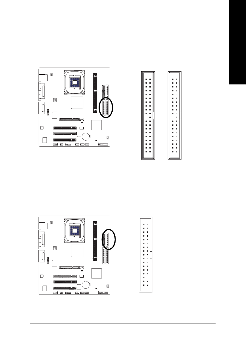
5) IDE1/IDE2 (IDE Connector)
An IDE device connects to the computer via an IDE connector. One IDE connector can connect to one
IDE cable, and the single IDE cable can then connect to two IDE devices (hard drive or optical drive). If
you wish to connect two IDE devices, please set the jumper on one IDE device as Master and the other
as Slave(for information on settings, please refer to the instructions located on the IDE device).
English
40
55
21
IDE2 Connector
40 39
39
21
IDE1 Connector
6) FDD (FDD Connector)
The FDD connector is used to connect the FDD cable while the other end of the cable connects to the
FDD drive. The types of FDD drives supported are: 360KB, 720KB, 1.2MB, 1.44MB and 2.88MB.
Please connect the red power connector wire to the pin1 position.
3334
55
12
Hardware Installation- 21 -
Page 22

English
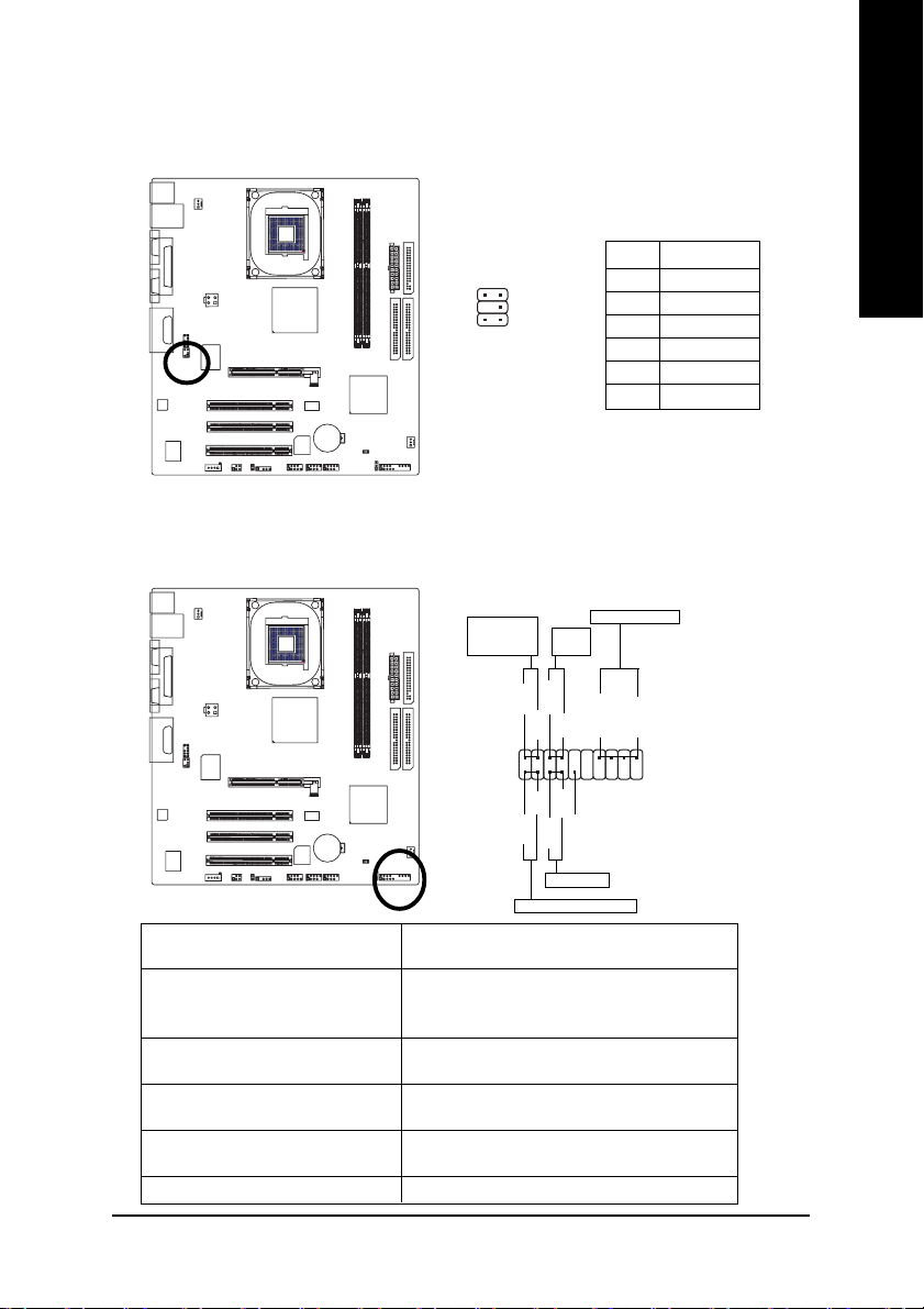
7) PWR_LED
PWR_LED is connected with the system power indicator to indicate whether the system is on/off.
It will blink when the system enters suspend mode.
Pin No. Definition
1
55
1 MPD+
2 MPD3 MPD-
8) F_AUDIO (Front Audio Panel Connector)
Please make sure the pin assigment on the cable is the same as the pin assigment on the MB header.
To find out if the chassis you are buying support front audio panel connector, please contact your
dealer. If you want to use "Front Audio" connector, you must remove the jumpers on Pin 5-6, 9-10.
Pin No. Definition
10 9
2
1
1 MIC
2 GND
3 REF
4 POWER
5 FrontAudio(R)
6 RearAudio(R)
7 Reserved
8 No Pin
9 FrontAudio (L)
10 RearAudio (L)
55
GA-8GEM800 Motherboard - 22 -
Page 23
9) SUR_CEN
Please contact your nearest dealer for optional SUR_CEN cable.
Pin No. Definition
1 SUR OUTL
2 SUR OUTR
1652
55
3 GND
4 No Pin
5 CENTER_OUT
6 BASS_OUT
10) F_PANEL (Front Panel Jumper)
Please connect the power LED, PC speaker, reset switch and power switch etc. of your chassis
front panel to the F_PANEL connector according to the pin assignment below.
English
Message LED/
Power/
Sleep LED
MSG+
2
1
HD+
55
IDE Hard Disk Active LED
HD (IDE Hard Disk Active LED) Pin 1: LED anode(+)
Pin 2: LED cathode(-)
SPEAK (Speaker Connector) Pin 1: VCC(+)
Pin 2- Pin 3: NC
Pin 4: Data(-)
RES (Reset Switch) Open: Normal Operation
Close: Reset Hardware System
PW (Power Switch) Open: Normal Operation
Close: Power On/Off
MSG(Message LED/Power/Sleep LED) Pin 1: LED anode(+)
Pin 2: LED cathode(-)
NC NC
Power
Switch
PW+
PW-
MSG-
HD-
RES+
RES-
Reset Switch
Speaker Connector
SPEAK+
NC
SPEAK-
20
19
Hardware Installation- 23 -
Page 24
English
11) CD_IN (CD IN, Black)
Connect CD-ROM or DVD-ROM audio out to the connector.
1
55
Pin No. Definition
1 CD-L
2 GND
3 GND
4 CD-R
12) SPDIF_IO (SPDIF In/ Out)
The SPDIF output is capable of providing digital audio to external speakers or compressed AC3
data to an external Dolby Digital Decoder. Use this feature only when your stereo system has
digital input function. Use SPDIF IN feature only when your device has digital output function.
Be careful with the polarity of the SPDIF_IO connector. Check the pin assignment carefully while
you connect the SPDIF_IO cable. Incorrect connection between the cable and connector will
make the device unable to work or even damage it. For optional SPDIF_IO cable, please contact
your local dealer.
55
GA-8GEM800 Motherboard - 24 -
Pin No. Definition
62
1
5
1 VCC
2 No Pin
3 SPDIF
4 SPDIFI
5 GND
6 GND
Page 25

13) F1_USB / F2_USB (Front USB Connectors, Yellow )
Be careful with the polarity of the front USB connector. Check the pin assignment carefully while
you connect the front USB cable, incorrect connection between the cable and connector will make
the device unable to work or even damage it. For optional front USB cable, please contact your
local dealer.
English
2
1
1
10
9
1 Power
2 Power
3 USB0 DX4 USB1 Dy5 USB0 DX+
6 USB1 Dy+
7 GND
8 GND
9 No Pin
10 NC
Pin No. Definition
55
14) CI (Chassis Intrusion, Case Open )
This 2-pin connector allows your system to enable or disable the "Case Open" item in BIOS, if the
system case begins remove.
1
Pin No. Definition
1 Signal
2 GND
55
Hardware Installation- 25 -
Page 26

English
15) IR
Be careful with the polarity of the IR connector while you connect the IR. Please contact you
nearest dealer for optional IR device.
Pin No. Definition
1VCC
1
55
2 No Pin
3 IR RX
4 GND
5 IR TX
16) COMB (COMB Connector)
Be careful with the polarity of the COMB connector. Check the pin assignment while you connect
the COMB cable. Please contact your nearest dealer for optional COMB cable.
55
GA-8GEM800 Motherboard - 26 -
10
2
19
Pin No. Definition
1 NDCDA2 NSINA
3 NSOUTA
4 NDTRA5 GND
6 NDSRA7 NRTSA8 NCTSA9 NRIA10 No Pin
Page 27

17) CLR_CMOS (Clear CMOS)
You may clear the CMOS data to its default values by this jumper. To clear CMOS, temporarily
short 1-2 pin. Default doesn’t include the “Shunter” to prevent improper use of this jumper.
Open: Normal
1
1
Short: Clear CMOS
55
18 ) BAT (Battery)
English
Danger of explosion if battery is incorrectly replaced.
Replace only with the same or equivalent type
recommended by the manufacturer.
Dispose of used batteries according to the manufacturer's
55
instructions.
If you want to erase CMOS...
1.Turn off the computer and unplug the power cord.
2.Remove the battery, wait for 30 second.
3.Re-install the battery.
4.Plug the power cord and turn ON the computer.
Hardware Installation- 27 -
Page 28

English
GA-8GEM800 Motherboard - 28 -
Page 29

Chapter 2 BIOS Setup
BIOS (Bas ic Input and Output System) includes a CMOS SETUP utility which allows user to configure
required s ettings or to activate certain system features.
The CMOS SETUP saves the c onfiguration in the CMOS SRAM of the motherboard.
When t he power is turned off, the battery on the motherboard supplies the necessary power to the CMOS
SRAM.
When the power is turned on, pushing the <Del> button during the BIOS POST (Power-On Self Test) will
take you to the CMOS SETUP screen. You can enter the BIOS setup screen by pressing "Ctrl + F1".
When setting up BIOS f or the first time, it is recommended that you save the current BIOS to a disk in the
event that BIOS needs to be res et to its original settings. If you wish to upgrade to a new BIOS, either
Gigabyte's Q-Flas h or @BIOS utility can be used.
Q-Flash allows the user to quickly and easily update or backup BIOS without entering the operat ing system.
@BIOS is a Windows-based utility that does not require users to boot to DOS before upgrading BIOS but
directly download and update BIOS from the Internet.
CONTROL KEYS
< >< >< >< > Move to select item
<Enter> Select Item
<Esc> Main Menu - Quit and not save changes into CMOS Status Page Setup Menu
and Opt ion Page Setup Menu - Exit current page and return to Main Menu
<Page Up> Increase the numeric value or make changes
<Page Down> Decrease the numeric value or make changes
<F1> General help, only for Status Page Setup Menu and Option Page Setup Menu
<F2> Item Help
<F5> Restore the previous CMOS value from CMOS, only for Option Page Setup Menu
<F6> Load the file-safe default CMOS v alue from BIOS default table
<F7> Load the Optimiz ed Defaults
<F8> Q-F lash utility
<F9> System Information
<F10> Save all the CMOS changes, only for M ain Menu
English
Main Menu
The on-line description of the highlighted setup function is displayed at the bottom of the screen.
Status Page Setup Men u / Option Page Setup Menu
Press F1 to pop up a small help window that describes the appropriate keys to use and the possible selections for the highlighted item. To exit the Help Window press <Esc>.
BIOS Setup- 29 -
Page 30

English
The Main Menu (For example: BIOS Ver. : E2)
Onc e you enter Award BIOS CMOS Setup Utility, the Main Menu (as figure below) will appear on the
screen. Use arrow keys to select among the items and press <Enter> to accept or enter the sub-menu.
CMOS Setup Utility-Cop yright (C) 1984-2004 Award Software
} Standard CMOS Features
} Advan ced BIOS Features
} Integrated Peripherals
} Power Management Setup
} PnP/PCI Configurations
} PC Health Status
} Frequency/Voltage C ontrol
Esc: Quit higf: Select Item
F8: Q-Flash F10: Save & Exit Setup
Time, Date, Hard Disk Type...
If you can't find the setting you want, please press "Ctrl+F1" to access hidden advanced
opt ions.
n Standard CMOS Featu res
This set up page includes all the items in standard compatible BIOS.
n Ad vanced BIOS Features
This set up page includes all the items of Award special enhanced features.
n In tegrated Peripherals
This setup page includes all onboard peripherals.
n Po wer Management Setup
This set up page includes all the items of Green function features.
n Pn P/PCI Configuration
This setup page includes all the configurat ions of PCI & PnP ISA resources.
n PC Health Status
This s etup page includes information about the system autodetected temperature, voltage, fan,
speed.
n Freq uency/Voltage Control
This setup page is to control CPU clock and frequency ratio.
n Top Performan ce
If y ou wish to maximize the performance of your system, enable Top Performance.
n Load Fail-Safe Defaults
Fail-Safe D efaults indicate the value of the system parameters with which the system would be
in s afe configuration.
n Lo ad Optimized Defaults
Opt imized Defaults indicate the value of the system parameters with which the system would be
in best performance configuration.
Top Perfo rmance
Load Fail-Safe Defaults
Load Optimized Defaults
Set Superviso r Password
Set User Password
Save & Exit Setup
Exit Without Saving
GA-8GEM800 M otherboard - 30 -
Page 31

n Set Supervisor Passwo rd
Change, set, or disable password. It allows you to limit access to the system and Setup, or just to Setup.
n Set User Password
Change, set , or disable password. It allows you to limit access to the system.
n Save & Exit Setup
Save CMOS value settings to CM OS and exit setup.
n Exit Without Saving
Abandon all CMOS value changes and exit setup.
English
BIOS Setup- 31 -
Page 32

English
2-1 Standard CMOS Features
CMOS Setu p Utility-Copyright (C) 1984-2004 Award Software
Date (mm:d d:yy) Thu, Ju ly 29 2004
Time (hh :mm:ss) 22:31:24
} IDE Primary Master [None]
} IDE Primary Slave [Non e]
} IDE Seco ndary Master [Non e]
} IDE Seco ndary Slave [Non e]
Drive A [1.44M, 3.5"]
Drive B [No ne]
Floppy 3 Mode Suppo rt [Disabled]
Halt On [All, Bu t Keyboard]
Base Memory 640K
Extend ed Memory 127M
Total Memory 128M
higf: Move Enter: Select +/-/PU/PD: Value F10: Save ESC: Exit F1: General Help
F5: Previous Values F6: Fail-Safe Defaults F7: Optimized Defaults
Date
The date form at is <week>, <month>, <day>, <year>.
Week The week, from Sun to Sat, determined by the BIOS and is displayed only.
Month The m onth, Jan. through Dec.
Day The day, from 1 to 31 (or the maximum allowed in the month).
Year The y ear, from 1999 through 2098.
Time
The times format in <hour> <minute> <second>. The time is calculated based on the 24-hour
military-time clock. For example, 1 p.m. is 13:00:00.
IDE Primary Master, Slave /IDE Secondary Master, Slave
IDE HDD Auto-Detect ion Press "Enter" to select this option for automatic device detection.
IDE Prim ary/Secondary Master(Slave) setup You can use one of the three methods below:
Auto Allows BIOS to automatically detect IDE devices during POST(default)
None Select this if no IDE devices are used and the system will skip the automatic
detection step and allow for faster system start up.
Manual User can manually input the correct settings
Access Mode Use this to set the access mode for the hard drive. The four options are:
CHS/ LBA/Large/Auto (Default:Auto)
Capacity Capac ity of currently installed hard disk.
Hard driv e information should be labeled on the outside drive casing.
Enter t he appropriate option based on this information.
Cy linder Number of cylinders
Head Number of heads
Prec omp Write precomp
Landing Zone Landing zone
Sec tor Number of sectors
Standard C MOS Features
Item Help
Menu Level }
Change the d ay, month,
ye ar
<Week>
Sun. to Sat.
<Mon th>
Jan. to Dec.
<Day>
1 to 31 (o r maximum
allowed in the month )
<Year>
1999 to 2098
GA-8GEM800 M otherboard - 32 -
Page 33

Drive A / Drive B
The category identifies the types of floppy disk drive A or drive B that has been installed in the computer.
None No floppy driv e installed
360K, 5.25" 5.25 inch PC-type standard drive; 360K byte capacity.
1.2M, 5.25" 5.25 inch AT-type high-density drive; 1.2M byte capacity
(3.5 inch when 3 Mode is Enabled).
720K, 3.5" 3.5 inch double-sided drive; 720K byte capacity
1.44M , 3.5" 3.5 inch double-sided drive; 1.44M byte capacity. (Default value)
2.88M , 3.5" 3.5 inch double-sided drive; 2.88M byte capacity.
Floppy 3 Mode Su pport (for Japan Area)
Disabled Normal Floppy Drive. (Def ault value)
Drive AA Drive A is 3 mode Floppy Drive.
Drive B Drive B is 3 mode Floppy Drive.
Bot h Drive A & B are 3 mode Floppy Drives.
Halt o n
The category determines whether the computer will stop if an error is detected during power up.
No Errors The system boot will not stop for any error t hat may be detected and you
will be prompted.
All Errors Whenever the BIOS detects a non-fatal error the system will be stopped.
All, But Keyboard The system boot will not stop for a keyboard error; it will stop for all other
errors. (Default value)
All, But Dis kette The system boot will not stop for a disk error; it will stop for all other errors.
All, But Dis k/Key The system boot will not stop for a keyboard or disk error; it will stop for all
other errors.
Memory
The c ategory is display-only and is determined by POST (Power On Self Test) of the BIOS.
Base Memory
The POST of the BIOS will determine the amount of base (or conventional) memory installed
in the system.
The value of the base memory is typically 512K for systems with 512K memory installed on
the motherboard, or 640K for systems with 640K or more memory installed on the motherboard.
Extend ed Memory
The BIOS determines how m uch extended memory is present during the POST.
This is the amount of memory located above 1 MB in the CPU's memory address map.
Total Memory
This it em displays the memory size that used.
English
BIOS Setup- 33 -
Page 34

2-2 Advanced BIOS Features
English
CMOS Setup Utility-Cop yright (C) 1984-2004 Award Software
} First Boot Device [Flop py]
Secon d Boot Device [HDD-0 ]
Third Bo ot Device [CDROM]
Boot Up Floppy Seek [Disabled ]
Password Check [Setup]
CPU Hy per-Threading
Limit CPUID Max. to 3
Init Disp lay First [Onboard/AGP]
Grap hics Aperture Size
Graphics Share Memory
higf: Move Enter: Select +/-/PU/PD: Value F10: Save ESC: Exit F1: General Help
F5: Previous Values F6: Fail-Safe Defaults F7: Optimized Defaults
note 1
note 2
note 3
note 4
Advanced BIOS Features
[En abled]
[En abled]
[128MB]
[8MB]
Item Help
Menu Level }
Select Boot Device
Priority
[Flop py]
Boot from floppy
[LS120]
Boot from LS120
[HDD-0 ]
Boot fro m First HDD
[HDD-1 ]
Boot from second HDD
Not e1: This option is available only when the processor you install supports Intel® Hyper-
Threading Technology.
Not e2: This option is available only when you install an Intel® Pres cott processor (with
533MHz FSB).
Not e3/Note4 : This option is available only when you use the onboard VGA function.
First / Second / Third Boot Device
Floppy Select your boot device priority by Floppy.
LS120 Select your boot device priority by LS120.
HDD-0~3 Selec t your boot device priority by Hard Disk.
SCSI Select your boot device priority by SCSI.
CDROM Selec t your boot device priority by CDROM.
ZIP Selec t your boot device priority by ZIP.
USB-FD D Select your boot device priority by USB-FDD.
USB-Z IP Select your boot device priority by USB-ZIP.
USB-CDROM Select your boot device priority by USB-CDROM.
USB-HD D Select your boot device priority by USB-HDD.
LAN Select your boot device priority by LAN.
Dis abled Select your boot device priority by Disabled.
GA-8GEM800 M otherboard - 34 -
Page 35

Boot Up Floppy Seek
During POST , BIOS will determine the floppy disk drive installed is 40 or 80 tracks. 360K
type is 40 tracks 720K, 1.2M and 1.44M are all 80 tracks.
Dis abled BIOS will not search for the type of floppy disk drive by track number. Note
that there will not be any warning message if the drive installed is 360K.
(Default value)
Enabled BIOS s earches for floppy disk drive to determine if it is 40 or 80 tracks. Note
that BIOS c an not tell from 720K, 1.2M or 1.44M drive type as they are all 80
tracks .
Password Check
Setup The system will boot but will not access to Setup page if the correct
pass word is not entered at the prompt. (Default value)
Sys tem The system will not boot and will not access to Setup page if the correct
pas sword is not entered at the prompt.
If you want to cancel the setting of password, please just press ENTER to make [SETUP] empty.
CPU Hyp er-Threading
This opt ion appears only when the processor you install supports Intel® Hyper-T hreading Technology.
Enabled Enable CPU H yper-Threading feature. Please note that this feature is only
working for operating s ystem with multiprocessors mode supported. (Default
value)
Dis abled Disable CPU Hyper-Threading.
Limit CPUID Max. to 3
This option is available only when you install an Intel® Pres cott processor (with 533MHz FSB).
Enabled Lim it CPUID Maximum value to 3 when using older OS like NT4. (Defaults
value)
Dis abled Disable CPUID Limit for Windows XP.
Init Display First
Select the first initiation of the monitor display from onboard/AGP or PCI VGA card.
PCI Set Init Display First to PCI VGA card.
Onboard/ AGP Set Init Display First to onboard/AGP VGA card.(Default value)
Graphics Apertu re Size
This option is available only when you use the onboard VGA function.
128MB Set Graphics Aperture Size to 128MB. (Default value)
Dis abled Disable this function.
Graphics Share Memory
This option is available only when you use the onboard VGA function.
8M B Set Graphics Share Memory to 8MB. (Default value)
1M B Set Graphics Share Memory to 1MB.
English
BIOS Setup- 35 -
Page 36

English
2-3 Integrated Peripherals
CMOS Setu p Utility-Copyright (C) 1984-2004 Award Software
On-Chip Primary PCI IDE [En abled]
On-C hip Secondary PCI IDE [Enabled
IDE1 Co nductor Cable [Auto]
IDE2 Co nductor Cable [Auto]
USB Controller [En abled]
USB Keybo ard Support [Disabled]
USB Mouse Support [Dis abled]
AC97 Audio [Au to]
Onbo ard H/W LAN [Enabled]
Onbo ard Serial Port 1 [3F8/IRQ4]
Onbo ard Serial Port 2 [2F8/IRQ3]
UART Mo de Select [No rm al]
x UR2 Duplex Mode [Half]
Onbo ard Parallel Port [378/IRQ7]
Parallel Port Mode [SPP]
x ECP Mode Use DMA 3
Game Port Address [201]
Midi Port Ad dress [Disab led]
x Midi Port IRQ 10
higf: Move Enter: Select +/-/PU/PD: Value F10: Save ESC: Exit F1: General Help
F5: Previous Values F6: Fail-Safe Defaults F7: Optimized Defaults
On-Chip Primary PCI IDE
Enabled Enable onboard 1st channel IDE port. (Default value)
Dis abled Disable onboard 1st channel IDE port.
On-Chip Secondary PCI IDE
Enabled Enable onboard 2nd channel IDE port. (Default value)
Dis abled Disable onboard 2nd channel IDE port.
IDE1 Conductor Cable
Auto BIOS autodetects IDE1 conductor cable .(Default Value)
ATA66/100 Set IDE1 Conductor Cable to ATA66/100/133 (Please make sure your
IDE device and cable are compatible with ATA66/100).
ATA33 Set IDE1 Conductor Cable to ATA33. (Please make sure your IDE
dev ice and cable are compatible with ATA33)
IDE2 Conductor Cable
Auto BIOS autodetects IDE2 conductor cable. (Default Value)
ATA66/100 Set IDE2 Conductor Cable to ATA66/100/133. (Please make sure your
IDE device and cable are compatible with ATA66/100)
ATA33 Set IDE2 Conductor Cable to ATA33. (Please make sure your IDE
dev ice and cable are compatible with ATA33)
USB Controller
Enabled Enable USB Controller. (Default value)
Dis abled Disable USB Controller.
Integrated Peripherals
Item Help
Menu Level }
If a hard d isk
controller card is
used, set at Disab led
[En abled]
Enab le onboard IDE
POR T
[Dis abled]
Disable onbo ard IDE
POR T
GA-8GEM800 M otherboard - 36 -
Page 37

USB Keyboard Su pport
Enabled Enable U SB Keyboard Support.
Dis abled Disable USB Keyboard Support. (Default value)
USB Mo use Support
Enabled Enable USB Mous e Support.
Dis abled Disable USB Mouse Support. (Default value)
AC97 Audio
Auto Auto det ect AC97 audio function. (Default value)
Dis abled Disable AC97 audio function.
Onboard H/W LAN
Enabled Enable Onboard H/W LAN function. (Default value)
Dis abled Disable this function.
Onboard Serial Port 1
Auto BIOS will automatic ally setup the Serial port 1 address.
3F 8/IRQ4 Enable onboard Serial port 1 and address is 3F8/IRQ4. (Default value)
2F 8/IRQ3 Enable onboard Serial port 1 and address is 2F8/IRQ3.
3E8/I RQ4 Enable onboard Serial port 1 and address is 3E8/IRQ4.
2E8/I RQ3 Enable onboard Serial port 1 and address is 2E8/IRQ3.
Dis abled Disable onboard Serial port 1.
Onboard Serial Port 2
Auto BIOS will aut omatically setup the Serial port 2 address.
3F 8/IRQ4 Enable onboard Serial port 2 and address is 3F8/IRQ4.
2F 8/IRQ3 Enable onboard Serial port 2 and address is 2F8/IRQ3. (Default value)
3E8/I RQ4 Enable onboard Serial port 2 and address is 3E8/IRQ4.
2E8/I RQ3 Enable onboard Serial port 2 and address is 2E8/IRQ3.
Dis abled Disable onboard Serial port 2.
UART Mod e Select
This item allows you to determine which Infra Red(IR) function of Onboard I/O chip.
Norm al Use as standard serial port. (Default value)
IrDA Use as IR and set to IrDA Mode.
ASKIR Use as IR and set to ASKIR Mode.
UR2 Duplex Mode
This feature allows you to seclect IR mode.
This function will available when "UART Mode Select" isn’t set at Normal.
Half IR Function Duplex Half. (Default value)
Full IR Function Duplex Full.
Onboard Parallel Port
Dis abled Disable onboard LPT port.
378/IR Q7 Enable onboard LPT port and address is 378/IRQ7. (Default value)
278/IR Q5 Enable onboard LPT port and address is 278/IRQ5.
3BC/I RQ7 Enable onboard LPT port and address is 3BC/IRQ7.
English
BIOS Setup- 37 -
Page 38

English
Parallel Port Mode
SPP Use Parallel port as Standard Parallel Port. (Default value)
EPP Use Parallel port as Enhanced Parallel Port.
EC P Use Parallel port as Extended Capabilities Port.
EC P+EPP Use Parallel port as ECP & EPP mode.
ECP Mode Use DMA
This option is available only when Parallel Port Mode is set to ECP or ECP+EPP.
3 Set ECP Mode Use DMA to 3. (Default value)
1 Set ECP Mode Use DMA to 1.
Game Port Address
Dis abled Disable this function
201 Enable this function and set gameport address to 201. (Default value)
209 Enable this function and set gameport address to 209.
Midi Port Address
Dis abled Disable this function (Default value)
330 Enable this function and set midiport address to 330.
300 Enable this function and set midiport address to 300.
Midi Port IRQ
This option is available when the Midi Port Address is not set to “Disabled.”
5 Set midiport IRQ to 5.
10 Set midiport IRQ to 10. (Default value)
GA-8GEM800 M otherboard - 38 -
Page 39

2-4 Power Management Setup
CMOS Setu p Utility-Copyright (C) 1984-2004 Award Software
ACPI Susp end Type [S1(POS)]
Soft-Off by PWR-BTTN [Ins tant-Off]
PME Event Wake Up [Enabled ]
ModemR ingOn/WakeOnLan [Enab led]
Res ume b y Alarm [Disabled]
x Date (o f Month) Alarm Eve ry da y
x Time (hh:mm:ss ) Alarm 0 : 0 : 0
Power On By Mou se [Disabled]
Power On By Keyboard [Disab led]
x KB Power ON Passwo rd Enter
AC BACK Function [Soft-Off]
higf: Move Enter: Select +/-/PU/PD: Value F10: Save ESC: Exit F1: General Help
F5: Previous Values F6: Fail-Safe Defaults F7: Optimized Defaults
ACPI Suspend Type
S1(POS) Set ACPI suspend type to S1/POS(Power On Suspend). (Default value)
S3(STR) Set ACPI suspend type t o S3/STR(Suspend To RAM).
Soft-Off by PWR-BTTN
Instant-offf Press power button then Power off instantly. (Default value)
Delay 4 Sec. Press pow er button 4 sec. to Power off. Enter suspend if button is pressed
less than 4 sec.
PME Event Wake Up
Disabled Disable this function.
Enabled Enable PME Event Wake up. (Default value)
ModemRingOn/WakeO nLan
Dis abled Disable ModemRingOn/WakeOnLan function. (Default value)
Enabled Enable M odemRingOn/WakeOnLan function.
Resume b y Alarm
You can set "Resume by Alarm" item to enabled and key in date/time to power on system.
Disabled Disable this function. (Default value)
Enabled Enable alarm funct ion to turn on system.
If Resume by Alarm is Enabled:
Date (of Month) Alarm : Everyday, 1~31
Time (hh: mm: ss ) Alarm : (0~23) : (0~59) : (0~59)
Power On By Mouse
Dis abled Disable this function. (Default value)
Double Click Double-c lick PS/2 mouse left button to power on the system.
Power Management Setup
Item Help
Menu Level }
[S1]
Set suspend type to
Power On Suspend under
ACPI OS
[S3]
Set suspend type to
Suspend to RAM under
ACPI OS
English
BIOS Setup- 39 -
Page 40

English
Power O n By Keyboard
Pas sword Enter from 1 to 5 characters to set the Keyboard Power On Password.
Dis abled Disabled this function. (Default value)
Keyboard 98 I f your keyboard have "POWER Key" button, you can press the key to
power on the system.
KB Power ON Password
When "Power On by Keyboard" is set at Password, you can set the password here.
Enter Input password (from 1 to 5 characters) and press Enter to set the Keyboard
Power On password.
AC BACK Function
Soft-Offf When AC-power back to the system, the system will be in "Off" state.
(Default value)
Full-On When AC-power back to the system, the system always in "On" state.
Memory When AC-power back to the system, the system will return to the Last state
before AC-power off.
GA-8GEM800 M otherboard - 40 -
Page 41

2-5 PnP/PCI Configurations
CMOS Setup Utility-Cop yright (C) 1984-2004 Award Software
PCI1 IRQ Assignment [Au to]
PCI2 IRQ Assignment [Au to]
PCI3 IRQ Assignment [Au to]
higf: Move Enter: Select +/-/PU/PD: Value F10: Save ESC: Exit F1: General Help
F5: Previous Values F6: Fail-Safe Defaults F7: Optimized Defau lts
PCI1 IRQ Assignment
Aut o Auto assign IRQ to PCI 1. (Default value)
3,4,5, 7,9,10,11,12,14,15 Set IRQ 3,4,5,7,9,10,11,12,14,15 to PCI 1.
PCI2 IRQ Assignment
Aut o Auto assign IRQ to PCI 2. (Default value)
3, 4,5,7,9,10,11,12,14,15 Set IRQ 3,4,5,7,9,10,11,12,14,15 to PCI 2.
PCI3 IRQ Assignment
Auto Auto assign IRQ to PCI 3. (Default value)
3, 4,5,7,9,10,11,12,14,15 Set IRQ 3,4,5,7,9,10,11,12,14,15 to PCI 3.
PnP/PCI Configurations
Item Help
Menu Level }
Device(s) using this
INT:
USB1.1 Host Cntrlr
-Bus 0 Dev29 Func 2
English
BIOS Setup- 41 -
Page 42

English
2-6 PC Health Status
CMOS Setup Utility-Cop yright (C) 1984-2004 Award Software
Reset Case Open Status [Disabled]
Case Opened Yes
Vcore OK
DDR 25V OK
+3.3V OK
+12V OK
Curren t CPU Temperature 33oC
Current CPU FAN Speed 4687 RPM
Current SYSTEM FAN Speed 0 R PM
CPU Warn ing Temperature [Dis abled]
CPU FAN Fail Warning [Disabled]
SYSTEM FAN Fail Warning [Disabled ]
higf: Move Enter: Select +/-/PU/PD: Value F10: Save ESC: Exit F1: General Help
F5: Previou s Values F6: Fail-Safe Defaults F7: Optimized Defaults
Reset Case Open Status
Dis abled Don't reset case open status. (Default value)
Eabled Clear case open status at next boot.
Case Opened
If the case is closed, Case Opened will show "No".
If the case have been opened, Case Opened will show "Yes".
If you want to reset "Case Opened" value, enable Reset Case Open Status and save
CMOS, your computer will restart.
Current Voltage(V) Vcore / DDR25V / +3.3V / + 12V
Det ect system's voltage status automatically.
Current CPU Temperature
Detect CPU temperature automatically.
Current CPU/SYSTEM FAN Speed (RPM)
Det ect CPU/SYSTEM Fan speed status automatically.
CPU Warnin g Temperature
60oC / 140oF Monitor C PU temperature at 60oC / 140oF.
70oC / 158oF Monitor CPU temperature at 70oC / 158oF.
80oC / 176oF Monitor CPU temperature at 80oC / 176oF.
90oC / 194oF Monitor CPU temperature at 90oC / 194oF.
Disabled Disable this func tion. (Default value)
CPU/SYST EM FAN Fail Warning
Dis abled Disable fan warning function . (Default value)
Enabled Enable fan warning function.
PC Health Status
Item Help
Menu Level }
[Disabled]
Don’t reset case
open status
[Enabled]
Clear case open status
and set to be Disabled
at next boot
GA-8GEM800 M otherboard - 42 -
Page 43

2-7 Frequency/Voltage Control
CMOS Setu p Utility-Copyright (C) 1984-2004 Award Software
CPU Clock Ratio [15X]
CPU Host Clock Control [Disabled]
x CPU Ho st Frequency (Mhz) 133
x Fixed PCI/AGP Frequency 33/66
Host/DRAM Clock ratio Auto
Memory Frequency (Mhz) 266
PCI/AGP Frequ ency (Mhz) 33/66
higf: Move Enter: Select +/-/PU/PD: Value F10: Save ESC: Exit F1: General Help
F5: Previous Values F6: Fail-Safe Defaults F7: Optimized Defau lts
Incorrect using these features may cause your system broken. For power end-user use only.
CPU Clock Ratio
This setup option will be automatically assigned by CPU detection.
The option will display "Locked" and read only if the CPU ratio is not changeable.
CPU Host Clock Control
Please note t hat if your system is overclocked and cannot restart, please wait 20 secs.
for automatic sy stem restart or clear the CMOS setup data and perform a safe restart.
Dis abled Disable CPU Host Clock Control. (Default value)
Enabled Enable CPU Host Clock Control.
CPU Host Frequen cy (Mhz)
This item will be available when "CPU Host Clock Control" is set to Enabled.
100MHz ~ 355MHz Set CPU Host Clock from 100MHz to 355MHz.
Inappropriate using it may cause your system corrupted. For power End-User use only!
Fixed PCI/AGP Frequency
You can choose those modes to adjust PCI/AGP frequency. (Select PCI/AGP frequency
asynchronous with CPU frequency).
Frequ ency/Voltage Control
Item Help
Menu Level }
Set CPU Ratio if CPU
Ratio is unclocked
English
BIOS Setup- 43 -
Page 44

English
Host/DRAM Clock ratio
F or FSB (Front Side Bus) frequency=400MHz,
2.0 Memory Frequency = Host clock X 2.0.
2.66 Memory Frequency = Host clock X 2.66.
Auto Set Memory frequency by DRAM SPD data. (Default value)
F or FSB (Front Side Bus) frequency=533MHz,
2.0 Memory Frequency = Host clock X 2.0.
2.5 Memory Frequency = Host clock X 2.5.
Auto Set Memory frequency by DRAM SPD data. (Default value)
Memory Frequency (Mhz)
The values depend on CPU Host Frequency.
PCI/AGP Frequen cy (Mhz)
The values depend on Fixed PCI/AGP Frequency.
2-8 Top Performance
CMOS Setup Utility-Cop yright (C) 1984-2004 Award Software
} Standard CMOS Features
} Advanced BIOS Features
} Integrated Peripherals
} Power Management Setup
} PnP/PC I Configurations
} PC Health Status
} Frequency/Voltage C ontrol
Esc: Quit higf: Select Item
F8: Q-Flash F10: Save & Exit Setup
Top Perfo rmance
Disabled.........................[n ]
Enab led..........................[ ]
hi: Move ENTER: Accep t
ESC: Abort
Load Fail-Safe Defaults
Top Perfo rmance
Lo ad Fail-Safe Defaults
Load Optimized Defaults
Set Sup ervisor Password
Set User Password
Save & Ex it Setup
Exit Without Saving
If you wish to maximize the performance of your system, enable "Top Performance."
Dis abled Dis able this function. (Default Value)
Enabled Enable Top Performance function.
"Top Perform ance" will increase H/W working speed. Different system configuration (both H/W
component and OS) w ill effect the result. For example, the same H/W configuration might not run
properly with W indows XP, but works smoothly with Windows NT. Therefore, if your system is not
perf orm enough, the reliability or stability problem will appear sometimes, and we will recommend you
dis abling the option to avoid the problem as mentioned above.
GA-8GEM800 M otherboard - 44 -
Page 45

2-9 Load Fail-Safe Defaults
CMOS Setup Utility-Cop yright (C) 1984-2004 Award Software
} Standard CMOS Features
} Advanced BIOS Features
} Integrated Peripherals
} Power Management Setup
} PnP/PC I Configurations
} PC Health Status
} Frequency/Voltage C ontrol
Esc: Quit higf: Select Item
F8: Q-Flash F10: Save & Exit Setup
Load Fail-Safe Defau lts (Y/N)? N
Load Fail-Safe Defaults
Top Perfo rmance
Load Fail-Safe Defaults
Load Optimized Defaults
Set Sup ervisor Password
Set User Password
Save & Ex it Setup
Exit Without Saving
Fail-Safe defaults contain the most appropriate values of the system parameters that allow minimum system
perform ance.
2-10 Load Optimized Defaults
CMOS Setup Utility-Cop yright (C) 1984-2004 Award Software
} Standard CMOS Features
} Advanced BIOS Features
} Integrated Peripherals
} Power Management Setup
} PnP/PC I Configurations
} PC Health Status
} Frequency/Voltage C ontrol
Esc: Quit higf: Select Item
F8: Q-Flash F10: Save & Exit Setup
Load Optimized Defau lts (Y/N)? N
Load Optimized Defaults
Top Perfo rmance
Load Fail-Safe Defaults
Load Optimized Defaults
Set Sup ervisor Password
Set User Password
Save & Ex it Setup
Exit Without Saving
English
Selecting this field loads the fac tory defaults for BIOS and Chipset Features which the system automatically
detects.
BIOS Setup- 45 -
Page 46

English
2-11 Set Supervisor/User Password
CMOS Setup Utility-Cop yright (C) 1984-2004 Award Software
} Standard CMOS Features
} Advanced BIOS Features
} Integrated Peripherals
} Power Management Setup
} PnP/PC I Configurations
} PC Health Status
} Frequency/Voltage C ontrol
Esc: Quit higf: Select Item
F8: Q-Flash F10: Save & Exit Setup
Enter Password:
Change/Set/Disable Password
Selecting this field loads the fac tory defaults for BIOS and Chipset Features which the system automatically
detects.
When you select this function, the following message will appear at the center of the screen to assist you in
creating a password.
Type the password, up to eight characters, and press <Enter>. You will be asked to confirm the password.
Type the password again and press <Enter>. You may also press <Esc> to abort the selection and not enter
a password.
To disable password, just press <Enter> when you are prompted to enter password. A message
"PASSWORD DISABLED" will appear to confirm the password being disabled. Once the password is disabled,
the syst em will boot and you can enter Setup freely.
The BIOS Setup program allows you to specify two separate passwords:
SUPERVISOR PASSWORD and a USER PASSWORD. When disabled, anyone may access all BIOS Setup
program function. When enabled, the Supervisor passw ord is required for entering the BIOS Setup program
and having full configuration fields, the User password is required to access only basic items.
If you s elect "System" at "Password Check" in Advance BIOS Features Menu, you will be prompted for the
password every time the system is rebooted or any time you try to enter Setup Menu.
If you select "Setup" at "Password Check" in Advance BIOS Features Menu, you will be prompted only when
you try to enter Setup.
Top Perfo rmance
Load Fail-Safe Defaults
Load Optimized Defaults
Set Sup ervisor Password
Set User Password
Save & Ex it Setup
Exit Without Saving
GA-8GEM800 M otherboard - 46 -
Page 47

2-12 Save & Exit Setup
CMOS Setup Utility-Cop yright (C) 1984-2004 Award Software
} Standard CMOS Features
} Advanced BIOS Features
} Integrated Peripherals
} Power Management Setup
} PnP/PC I Configurations
} PC Health Status
} Frequency/Voltage C ontrol
Esc: Quit higf: Select Item
F8: Q-Flash F10: Save & Exit Setup
Save to CMOS and EXIT (Y/N)? Y
Save & Ex it Setup
Top Perfo rmance
Load Fail-Safe Defaults
Load Optimized Defaults
Set Sup ervisor Password
Set User Password
Save & Ex it Setup
Exit Without Saving
Type "Y" will quit the Set up Utility and save the user setup value to RTC CMOS.
Type "N" will return to Setup Utility.
2-13 Exit Without Saving
CMOS Setup Utility-Cop yright (C) 1984-2004 Award Software
} Standard CMOS Features
} Advanced BIOS Features
} Integrated Peripherals
} Power Management Setup
} PnP/PC I Configurations
} PC Health Status
} Frequency/Voltage C ontrol
Esc: Quit higf: Select Item
F8: Q-Flash F10: Save & Exit Setup
Quit Without Saving (Y/N)? N
Abandon all Data
Top Perfo rmance
Lo ad Fail-Safe Defaults
Load Optimized Defaults
Set Sup ervisor Password
Set User Password
Save & Ex it Setup
Exit Without Saving
English
Type "Y" will quit the Setup Utility without saving to RTC CMOS.
Type "N" will return to Setup Utility.
BIOS Setup- 47 -
Page 48

English
GA-8GEM800 M otherboard - 48 -
Page 49

Chapter 3Drivers Installation
Pictures below are shown in Windows XP.
(1) Please make sure to install the latest service pack for Windows after OS installation and
bef ore installing motherboard drivers.
(2) I nsert the driver CD that came with your motherboard into your CD-ROM drive, the driver
CD will auto start and installation screen will appear. If not, please double click the CD-ROM
device ic on in My computer or execute the Setup.exe in the root directory of the driver CD.
3-1 Install Chipset Dri vers
This page shows the drivers that need to be installed for the system. Click each item to install the driver
manually or c lick the Xpress Install button to install the drivers automatically.
Click the Xpress Install button to install drivers automatically.
Or click one driver at one time to
ins tall it manually.
The Xpress Install uses the"Click and Go" technology to install the drivers automatically. Just select the
drivers you want then click the "GO" button. The Xpress Install will execute the installation for you by
itself.
English
We rec ommend that you install all components in the list.
Som e device drivers will restart your system aut omatically. After restarting your
syst em the "Xpress Install" will continue to
ins tall other drivers.
System w ill reboot automatically after installing t he drivers, afterward you can install others applications.
Click " GO".
For U SB2.0 driver support under Windows XP operating system, please use Windows
Serv ice Pack. After install Windows Service Pack, it will show a question mark "?" in
"U niversal Serial Bus controller" under "Device Manager". Please remove the question
mark and restart the system (System will auto-detect the right USB2.0 driver).
Drivers Inst allation- 49 -
Page 50

English
3-2 Software Applications
This page displays all the tools that Gigabyte developed and some free software, you can choose anyone
you want and press "install" to install them.
3-3 Driver CD Information
This page lis ts the contents of software and drivers in this CD-title.
GA-8GEM800 M otherboard - 50 -
Page 51

3-4 Hardware Information
This page lists all devices you have for this motherboard.
3-5 Contact Us
Please s ee the last page for details.
English
Drivers Inst allation- 51 -
Page 52

English
GA-8GEM800 M otherboard - 52 -
Page 53

Chapter 4 Appendix
4-1 Unique Software Util ity
(Not all models support these unique software utilities, please check your motherboard features.)
4-1-1 Xpress Recovery Introduction
What is Xpress Recovery ?
Xpress Recovery is a utility used to back up and restore an OS
partition. If the hard drive is not working properly, then users can
rest ore the drive to its original state.
1. Supports FAT16, FAT32, and NTFS formats
2. Must be connected to the IDE1 Master
3. Allows installation of only one OS
4. Must be used with an IDE hard disk supporting HPA
5. The first part ition must be set as the boot partition. When the boot partition is backed up,
please do not alter it s size.
6. Xpress Recovery is recommended when you use Ghost to return boot manager to
NTF S format.
How to use the Xpress Recovery
1. Boot from CD-ROM (BMP Mode)
Enter t he BIOS menu, select "Advanced BIOS Feature" and set to boot from CD-ROM. Insert the
provided driver CD into your CD drive, then save and exit the BIOS menu. Once the computer has
restart ed, the phrase "Boot from CD:" will appear at the bottom left-hand corner of the screen. When
"Boot from CD:" appears, press any key to enter Xpress Recovery.
Once y ou have completed this step, subsequent access to Xpress Recovery can also function by
press ing the F9 key during computer power on.
.
.
Verifying DMI Pool Data
Boot from CD:
Boot from CD:
English
Xpress Recovery V1.0 (C) Copy Right 2003. GIGABYTE Technology CO. , Ltd.
1. Execut e Backup Utility
2. Ex ecute Restore Utility
3. Remove Back up Image
4. Set Password
5. Ex it and Restart
Build 2011
Appendix- 53 -
Page 54

2. Press F 9 during powering on the computer. (Text Mode)
Press F9 during powering on the computer .
English
Award Modular BIOS v6.00PG, An Energy Star Al ly
Copyright (C) 1984-2004, Award Software, Inc.
Intel 865PE AGPSet BIOS for 8IPE1000MT F1
Check System Health OK
.
.
.
Press DEL to enter SETUP / Q-Flash, F9 For Xpress Recovery
08 /1 6/2002 -I845 GE-6A69YG01C-00
Xpress Recovery V1.0 (C) Copy Right 2003. GIGABYTE Technology CO. , Ltd.
1. Execut e Backup Utility
2. Ex ecute Restore Utility
3. Remove Back up Image
4. Set Password
5. Ex it and Restart
F9 For Xpress Recovery
1. If you have already entered Xpress Recovery by booting from the CD-ROM, you can
ent er Xpress Recovery in the future by pressing the F9 key.
2. Sys tem storage capacity as well as drive reading/writing speed will affect backup
speed.
3. It is recommended that Xpress Recovery be immediately installed after OS and all
required driver and software installations are complete.
GA-8GEM800 M otherboard - 54 -
Page 55

1. Execute Backup Utility:
! Press B to Backup your System or Esc to Exit
The bac kup utility will automatically scan your system and back up data as a backup image in
your hard drive.
Not all systems support access to Xpress Recovery by pressing the F9 key during computer
pow er on. If this is the case, please use the boot from CD-ROM method to enter Xpress
Recov ery.
2. Execute Restore Utility:
! This program w ill recover your system to factory default.
Press R to restore your system back to facto ry default or press Esc to exit
Res tores backup image to original state.
3. Remove Backup Image:
! Remove backup image. Are you sure? (Y/N)
Remove t he backup image.
4. Set Password:
! Please in put a 4-16 character long password (a-z or 0-9) or press Esc to exit
You can set a password to enter Xpress Recovery to protect your hard disk data. Once this is
done, pass word input will be required to enter Xpress Recovery during the next as well as
subsequent system restarts. If you wish to remove the need for password entry, please select
"Set Password" and under "New Password/Confirm Password", make sure there is no entry and
then press "Enter" to remove password requirement.
English
5. Exit and Restart:
Exit and restart your computer.
Appendix- 55 -
Page 56

English
4-1-2 BIOS Flash Method Introduct ion
Method 1 : Q-FlashTM Utility
Q-FlashTM is a BIOS flash utility embedded in Flash ROM. With this
utility, users only have to stay in the BIOS menu when they want to
update BIOS. Q-Flash
utilit y in DOS or Windows. Using Q-FlashTM indicating no more fooling around with any complicated
ins tructions and operating system since it is in the BIOS menu.
Pleas e note that because updating BIOS has potential risk, please do it with caution!! We are
sorry that Gigabyte Technology Co., Ltd is not responsible for damages of system because
of inc orrect manipulation of updating BIOS to avoid any claims from end-users.
Before You Begin:
Before you s tart updating BIOS with the Q-FlashTM utility, please follow the steps below first.
1. Dow nload the latest BIOS for your motherboard from Gigabyte's website.
2. Ext ract the BIOS file downloaded and save the BIOS file (the one with model name.Fxx. For
example, 8KNXPU.Fba) to a floppy disk.
3. Reboot your PC and press Del to enter BIOS menu.
The BIOS upgrading guides below are separated into two parts.
If your motherboard has dual-BIOS, please refer to Part One.
If your motherboard has single-BIOS, please refer to Part Two.
Part O ne:
Updating BIO S with Q-FlashTM Utility o n Dual BIOS Motherboards.
Some of Gigabyte mot herboards are equipped with dual BIOS. In the BIOS menu of the motherboards
supporting Q-Flash and Dual BIOS, the Q-Flash utility and Dual BIOS utility are combined in the same
screen. This sec tion only deals with how to use Q-Flash utility.
In the foll owing sections, we take GA-8KNXP Ultra as the example to guide you how to flash
BI OS from an older version to the latest version. For example, from Fa3 to Fba.
TM
allows users to flash BIOS without any
Award Mod ular BI OS v6.00PG, An Energy S tar
Ally
Copyright (C) 1984-2003, Award S oftwar e, Inc .
The BIOS file is Fa3
before updating
Intel i875P AGP s et BIO S f or 8KNXP Ultr a Fa3
Check System Health O K , VCo re = 1.5250
Main P ro ce ss or : Int el P entium(R) 4 1.6GHz (133x12)
<CPUID : 0F27 Pa tch I D : 0027>
Memory T es ting : 131072K OK
Memory Frequency 266 MHz in S ingle Channel
Primary Maste r : FUJITS U MPE3170AT ED-03-08
Primary S lave : No ne
Secondary Mast er : CREATIVEDVD-RM DVD1242E BC101
Secondary Slave : None
Press DEL t o enter SETUP / Dual BIO S / Q-Flas h / F9 For
Xpress R ec overy
08/07/2003-i875P-6A79BG03C-00
GA-8GEM800 M otherboard - 56 -
Page 57

Entering the Q-FlashTM utility:
Step1: To use Q-Flash utility, you must press Del in the boot screen to enter BIOS menu.
CMOS Setu p Utility-Copyright (C) 1984-2004 Award Software
} Standard CMOS Features
} Advanced BIOS Featu res
} In tegrated Peripherals
} Po wer Management Setup
} PnP/PCI Configurations
} PC Health Status
} MB Intelligent Tweaker(M.I.T.)
ESC: Quit F3: Change Language
F8: Dual BIOS/Q-Flash F10: Save & Exit Setup
Time, Date, Hard Disk Type...
Select Language
Load Fail-Safe Defaults
Load Optimized Defaults
Set Superviso r Password
Set User Pas sword
Save & Exit Setup
Exit Without Saving
Step 2: Press F8 button on your keyboard and then Y button to enter the Dual BIOS/Q-Flash utility.
Exploring the Q -FlashTM / Dual BIOS utility screen
The Q-Flash / Dual BIOS utility screen consists of the following key components.
English
Task menu for
Dual BIOS
utilit y
Task menu for
TM
Q-Flash
utility
Boot From......................................... Main Bios
Main ROM Type/Size.............................SST 49LF004A 512K
Backup ROM Type/Size.........................SST 49LF004A 512K
Wide Range Protection Disab le
Copy Main ROM Data to Backup
Enter : Run hi:Move ESC:Reset F10:Power Off
Dual BIOS Utility
Boot From Main Bios
Auto Recovery Enable
Halt On Erro r Disable
Load Default Settings
Save Settings to CMOS
Q-Flash Utility
Load Main BIOS from Flopp y
Load Backup BIOS from Flopp y
Save Main BIOS to Floppy
Save Backup BIOS to Floppy
Dual BIOS utility bar
Q-FlashTM utility title
ba r
Action bar
Task menu for Dual BIOS utility:
Cont ains the names of eight tasks and two item showing information about the BIOS ROM type.
Blocking a task and pres sing Enter key on your keyboard to enable execution of the task.
Task menu fo r Q-Flash utility:
Cont ains the names of four tasks. Blocking a task and pressing Enter key on your keyboard to enable
exec ution of the task.
Action bar:
Contains the names of four actions needed to operate the Q-Flash/Dual BIOS utility. Pressing the buttons
mentioned on your keyboards to perform these actions.
Appendix- 57 -
Page 58

English
Using the Q-FlashTM utility:
This section tells you how to update BIOS using the Q-Flash utility. As described in the "Before you
begin" section above, you must prepare a floppy disk having the BIOS file for your motherboard and
ins ert it to your computer. If you have already put the floppy disk into your system and have entered
the Q-Flash utility, please follow the steps below to flash BIOS.
Steps:
1. Pres s arrow buttons on your keyboard to move the light bar to "Load Main BIOS from Floppy" item
in the Q-Flash menu and press Enter button.
Lat er, you will see a box pop up showing the BIOS files you previously downloaded to the floppy
disk .
If you want to save the current BIOS for backup purpose, you can begin Step 1 with "Save
Main BIOS to Floppy" item.
2. Move to t he BIOS file you want to flash and press Enter.
In this example, we only dow nload one BIOS file to the floppy disk so only one BIOS file,
8KNXPU.Fba, is listed .
Please confirm again you have the correct BIOS file for your motherboard.
Boot From......................................... Main Bios
Main ROM Type/Size.............................SST 49LF004A 512K
Backup ROM Type/Size.........................SST 49LF004A 512K
Wide Range Protection Disab le
8KNXPU.Fba 512K
T otal size : 1.39M Free size : 911.50K
Copy Main ROM Data to Backup
F5 : Refresh DEL : Delete
Enter : Run hi:Move ESC:Reset F10:Power Off
After press ing Enter, you'll then see the progress of reading the BIOS file from the floppy disk.
Boot From......................................... Main Bios
Main ROM Type/Size.............................SST 49LF004A 512K
Backup ROM Type/Size.........................SST 49LF004A 512K
Wide Range Protection Disab le
Read ing BIOS file from floppy ...
>>>>>>>>>>>>>>.....................
Copy Main ROM Data to Backup
Don't Turn Off Power or Res et System
Enter : Run hi:Move ESC:Reset F10:Power Off
Aft er BIOS file is read, you'll see a dialog box asking you "Are you sure to update BIOS?"
GA-8GEM800 M otherboard - 58 -
Dual BIOS Utility
1 file(s ) found
Boot From Main Bios
Auto Recovery Enable
Halt On Erro r Disable
Load Default Settings
Save Settings to CMOS
Q-Flash Utility
Load Main BIOS from Flopp y
Load Backup BIOS from Flopp y
Save Main BIOS to Floppy
Save Backup BIOS to Floppy
Dual BIOS Utility
Boot From Main Bios
Auto Recovery Enable
Halt On Erro r Disable
Load Default Settings
Save Settings to CMOS
Q-Flash Utility
Load Main BIOS from Flopp y
Load Backup BIOS from Flopp y
Save Main BIOS to Floppy
Save Backup BIOS to Floppy
BIOS f ile in the floppy
disk.
Do not trun off power or
reset your system at this
stage!!
Page 59

3. Press Y button on your keyboard after you are sure to update BIOS.
Then it will begin to update BIOS. The progress of updating BIOS will be displayed.
Please do not take out the floppy disk when it begins flashing BIOS.
4. Press any keys to return to the Q-Flash menu when the BIOS updating procedure is completed.
Boot From......................................... Main Bios
Main ROM Type/Size.............................SST 49LF004A 512K
Backup ROM Type/Size.........................SST 49LF004A 512K
Wide Range Protection Disab le
Copy Main ROM Data to Backup
Enter : Run hi:Move ESC:Reset F10:Power Off
Dual BIOS Utility
Boot From Main Bios
Auto Recovery Enable
!! Copy BIOS completed - Pass !!
Halt On Erro r Disable
Please press any key to continue
Load Default Settings
Save Settings to CMOS
Q-Flash Utility
Load Main BIOS from Flopp y
Load Backup BIOS from Flopp y
Save Main BIOS to Floppy
Save Backup BIOS to Floppy
You can repeat Step 1 to 4
to flash the backup BIOS,
too.
5. Press Esc and then Y button to exit the Q-Flash utility. The computer will restart automatically after
you exit Q-Flash.
Boot From......................................... Main Bios
Main ROM Type/Size.............................SST 49LF004A 512K
Backup ROM Type/Size.........................SST 49LF004A 512K
Wide Range Protection Disab le
Copy Main ROM Data to Backup
Enter : Run hi:Move ESC:Reset F10:Power Off
Dual BIOS Utility
Boot From Main Bios
Auto Recovery Enable
Are you s ure to RESET ?
Halt On Erro r Disable
[Enter] to continure or [Es c] to abort...
Load Default Settings
Save Settings to CMOS
Q-Flash Utility
Load Main BIOS from Flopp y
Load Backup BIOS from Flopp y
Save Main BIOS to Floppy
Save Backup BIOS to Floppy
English
Af ter system reboots, you may find the BIOS version on your boot screen becomes the one you
flashed.
Award Mod ular BI OS v6.00PG, An Energy S tar
Ally
Copyright (C) 1984-2003, Award S oftwar e, Inc .
The BIOS file
becomes Fab after
updating.
Intel i875P AGP s et BIO S fo r 8KNXP Ultra Fba
Check System Health O K , VCo re = 1.5250
Main P ro ce ss or : Int el P entium(R) 4 1.6GHz (133x12)
<CPUID : 0F27 Pa tch I D : 0027>
Memory T es ting : 131072K OK
Memory Frequency 266 MHz in S ingle Channel
Primary Maste r : FUJITS U MPE3170AT ED-03-08
Primary S lave : No ne
Secondary Mast er : CREATIVEDVD-RM DVD1242E BC101
Secondary Slave : None
Press DEL t o enter SETUP / Dual BIO S / Q-Flas h / F9 For
Xpress R ec overy
09/23/2003-i875P-6A79BG03C-00
Appendix- 59 -
Page 60

English
6. Pres s Del to enter BIOS menu after system reboots. When you are in BIOS menu, move to
Load Fail-Safe Defaults item and press Enter to load BIOS Fail-Safe Defaults. Normally the
sys tem redetects all devices after BIOS has been upgraded. Therefore, we highly recommend
reloading the BIOS defaults after BIOS has been upgraded.
CMOS Setu p Utility-Copyright (C) 1984-2004 Award Software
} Standard CMOS Features
} Advanced BIOS Featu res
} In tegrated Peripherals
} Po wer Management Setup
} PnP/PCI Configurations
} PC Health Status
} MB Intelligent Tweaker(M.I.T.)
ESC: Quit F3: Change Language
F8: Dual BIOS/Q-Flash F10: Save & Exit Setup
Load Fail-Safe Defaults (Y/N)? Y
Time, Date, Hard Disk Type...
Select Language
Load Fail-Safe Defaults
Load Optimized Defaults
Set Superviso r Password
Set User Pas sword
Save & Exit Setup
Exit Without Saving
Press Y on y our keyboard to load defaults.
7. Select Save & Exit Setup item to save the settings to CMOS and exit the BIOS menu.
Sys tem will reboot after you exit the BIOS menu. The procedure is completed.
CMOS Setu p Utility-Copyright (C) 1984-2004 Award Software
} Standard CMOS Features
} Advanced BIOS Featu res
} In tegrated Peripherals
} Po wer Management Setup
} PnP/PCI Configurations
} PC Health Status
} MB Intelligent Tweaker(M.I.T.)
ESC: Quit F3: Change Language
F8: Dual BIOS/Q-Flash F10: Save & Exit Setup
Save to CMOS and EXIT (Y/N)? Y
Time, Date, Hard Disk Type...
Select Language
Load Fail-Safe Defaults
Load Optimized Defaults
Set Superviso r Password
Set User Pas sword
Save & Exit Setup
Exit Without Saving
Press Y on your keyboard to save and exit.
Part Two:
Updating BIO S with Q-FlashTM Utility o n Single-BIOS Motherboards.
This part guides users of single-BIOS motherboards how to update BIOS using the Q-Flash
CMOS Setu p Utility-Copyright (C) 1984-2004 Award Software
} Standard CMOS Features
} Advanced BIOS Featu res
} In tegrated Peripherals
} Po wer Management Setup
} PnP/PCI Configurations
} PC Health Status
} MB Intelligent Tweaker(M.I.T.)
ESC: Quit F3: Change Language
F8: Q-Flash F10: Save & Exit Setup
Time, Date, Hard Disk Type...
GA-8GEM800 M otherboard - 60 -
Top Perfo rmance
Load Fail-Safe Defaults
Load Optimized Defaults
Set Superviso r Password
Set User Pas sword
Save & Exit Setup
Exit Without Saving
TM
utility .
Page 61

Exploring the Q-FlashTM utility screen
The Q-FlashBIOS utility screen consists of the following key components.
Q-FlashTM util ity bar
Action bar
Task menu for
Q-FlashTM utility
Flash T ype/Size.................................SST 49LF002A 256K
Enter : Run hi:Move ESC:Reset F10:Power Off
Q-Flas h Utility V1.30
Keep DMI Data Enable
Update BIOS from Flopp y
Save BIOS to Floppy
Task menu fo r Q-Flash utility:
Cont ains the names of three tasks. Blocking a task and pressing Enter key on your keyboard to enable
exec ution of the task.
Action bar:
Contains the names of four actions needed to operate the Q-Flash utility. Pressing the buttons mentioned
on your k eyboards to perform these actions.
Using the Q-FlashTM utility:
This section tells you how to update BIOS using the Q-Flash utility. As described in the "Before you
begin" section above, you must prepare a floppy disk having the BIOS file for your motherboard and
ins ert it to your computer. If you have already put the floppy disk into your system and have entered
the Q-Flash utility, please follow the steps below to flash BIOS.
Steps:
1. Pres s arrow buttons on your keyboard to move the light bar to "Update BIOS from Floppy" item in
the Q-Flash menu and press Enter button.
Lat er, you will see a box pop up showing the BIOS files you previously downloaded to the floppy
disk .
If you want to save the current BIOS for backup purpose, you can begin Step 1 with "Save
BIOS t o Floppy" item.
2. Mov e to the BIOS file you want to flash and press Enter.
I n this example, we only download one BIOS file to the floppy disk so only one BIOS file,
8GE800.F 4, is listed.
Please confirm again you have the correct BIOS file for your motherboard.
Flash T ype/Size.................................SST 49LF002A 256K
8GE800.F4 256K
T otal size : 1.39M Free size : 1.14M
Enter : Run hi:Move ESC:Reset F10:Power Off
F5 : Refresh DEL : Delete
Q-Flas h Utility V1.30
1 file(s ) found
Keep DMI Data Enable
Update BIOS from Flopp y
Save BIOS to Floppy
BIOS file in the floppy
disk.
English
Flash T ype/Size.................................SST 49LF002A 256K
Read ing BIOS file from floppy ...
>>>>>>>>>>>>>>.....................
Enter : Run hi:Move ESC:Reset F10:Power Off
Don't Turn Off Power or Res et System
Q-Flas h Utility V1.30
Keep DMI Data Enable
Update BIOS from Flopp y
Save BIOS to Floppy
Do n ot trun off power or
reset your system at this
stage!!
Aft er BIOS file is read, you'll see a dialog box asking you "Are you sure to update BIOS?"
Please do not take out the floppy disk when it begins flashing BIOS.
Appendix- 61 -
Page 62

English
3. Press Y button on your keyboard after you are sure to update BIOS.
Then it will begin to update BIOS. The progress of updating BIOS will be shown at the same time.
Flash T ype/Size.................................SST 49LF002A 256K
>>>>>>>>>>>>>>>>>>>.........................
Enter : Run hi:Move ESC:Reset F10:Power Off
Don't Turn Off Power or Res et System
Q-Flas h Utility V1.30
Keep DMI Data Enable
Updating BIOS No w
Update BIOS from Flopp y
Save BIOS to Floppy
Do n ot trun off power or
reset your system
at this stage!!
4. Press any keys to return to the Q-Flash menu when the BIOS updating procedure is completed.
Flash T ype/Size.................................SST 49LF002A 256K
Enter : Run hi:Move ESC:Reset F10:Power Off
Q-Flas h Utility V1.30
Keep DMI Data Enable
!! Copy BIOS completed - Pass !!
Update BIOS from Flopp y
Save BIOS to Floppy
Please press any key to continue
5. Press Esc and then Y button to exit the Q-Flash utility. The computer will restart automatically after
you exit Q-Flash.
Flash T ype/Size.................................SST 49LF002A 256K
Enter : Run hi:Move ESC:Reset F10:Power Off
Q-Flas h Utility V1.30
Keep DMI Data Enable
Are you s ure to RESET ?
Update BIOS from Flopp y
Save BIOS to Floppy
[Enter] to continure or [Es c] to abort...
Af ter system reboots, you may find the BIOS version on your boot screen becomes the one you
flashed.
The BIOS file
becomes F4 after
updating
Award Mod ular BI OS v6.00PG, An Energy S tar
Ally
Copyright (C) 1984-2003, Award S oftwar e, Inc .
Intel 845GE AGPS et BIOS f or 8GE800 F4
Check System Health O K
Main P r oce ss or : Int el P entium(R) 4 1.7GHz ( 100x17.0)
<CPUID : 0F0A Pa tch ID : 0009>
Memory T est ing : 122880K OK + 8192K Share d Me mory
Primary Maste r : FUJITS U MPE3170AT ED-03-08
Primary S lave : No ne
Secondary Mast er : CREATIVEDVD-RM DVD1242E BC101
Secondary Slave : None
Press DEL t o enter SETUP / Q -Flas h
03/18/2003-I845GE-6A69YG01C-00
6. Pres s Del to enter BIOS menu after system reboots and "Load BIOS Fail-Safe Defaults". See how
to Load BIOS Fail-Safe Defaults, please kindly refer to Step 6 to 7 in Part One.
Congratulation!! Y ou have updated BIOS successfully!!
GA-8GEM800 M otherboard - 62 -
Page 63

Metho d 2 : @BIOSTM Utility
If you do not have a DOS startup disk, we recommend that you use
the new @BIOS utility. @BIOS allows users to update their BIOS
under W indows. Just select the desired @BIOS server to download
the latest version of BIOS.
Fig 1. Installing the @BIOS utility F ig 2. Installation complete and run @BIOS
Click Sart/ Programs/ GIGABYTE/@BIOS
Click @BIOS item to Install
Fig 3. The @BIOS utility Fig 4. Select the desired @BIOS server
Click "P" Click "Update New BIOS"
English
1. Methods and steps:
I. Update BIOS through the Internet
a. Select the Internet Update checkbox
b. C lick Update New BIOS
c . Select an @BIOSTM s ever from which you want to download BIOS
d. Select the exac t model name of your motherboard
e. Syst em will automatically download and update the BIOS.
II . Update BIOS NOT through the Internet:
a. D o not select the Internet Update checkbox
b. C lick Update New BIOS
c . Please select "All Files" in dialog box while opening the downloaded BIOS file.
d. Pleas e search for BIOS unzip file, downloading from the Internet or any other methods
(such as: 8I915G Pro.F1).
e. C omplete update process following the on-screen instructions.
Appendix- 63 -
Page 64

English
III. Save BIOS
In t he very beginning, there is Save Current BIOS icon shown in dialog box. It means to save the
current BIOS version.
IV. Check out supported motherboard and Flash ROM:
In the v ery beginning, there is "About this program" icon shown in dialog box. It can help you check
out whic h kind of motherboard and which brand of Flash ROM are supported.
2. Note:
I. In method I, if it shows two or more motherboard's model names to be selected, please make
sure your motherboard's model name again. Selecting wrong model name will cause the
sy stem unbooted.
II. In method II, be sure that motherboard's model name in BIOS unzip file are the same as your
mot herboard's. Otherwise, your system won't boot.
III. I n method I, if the BIOS file you need cannot be found in @BIOSTM s erver, please go onto
Gigabyt e's web site for downloading and updating it according to method II.
IV. Please note that any interruption during updating will cause system unbooted.
GA-8GEM800 M otherboard - 64 -
Page 65

4-1-3 2 / 4 / 6 Channel Audio Function Intr oduction
The follow ing setup is for Windows 98SE/2000/ME/XP. Please follow the steps below to enable the
funct ion!
2 Channel Audio Setu p:
We recommend that you use s peakers with amplifier to acquire the best sound effect if the stereo output
is applied.
ST EP 1:
Connect the stereo speakers or earphone to "Line
Out".
ST EP 2 :
Following installation of the audio driver, you find a
Sound Eff ect icon on the lower right hand
task bar. Click the icon to select the function.
Line Out
English
ST EP 3:
Select " Speaker Configuration", and choose the
"2-c hannel mode for stereo speaker output".
Appendix- 65 -
Page 66

English
4 Channel Analog Audio Output Mode
ST EP 1 :
Connect the front channels to "Line Out",
the rear channels to "Line In".
ST EP 2 :
Following installation of the audio driver, you find a
Sound Eff ect icon on the lower right hand
task bar. Click the icon to select the function.
ST EP 3 :
Select "Speak er Configuration", and choose the
"4-c hannel for 4 speaker output".
Dis able "Only SURROUND-KIT", and press
"OK".
Line Out
Line I n
When t he "Environment" setting is "None", the
sound would be performed as stereo mode
(2-c hannel output). Please select other settings for
4-channel output.
GA-8GEM800 M otherboard - 66 -
Page 67

Basic 6 Channel Analog Audio Output Mode
Us e the back audio panel to connect the audio
out put without any additional module.
ST EP 1 :
Connec t the front channels to "Line Out",the rear
channels to "Line In", and the Center/Subwoofer
channels to "MIC In".
ST EP 2 :
Following installation of the audio driver, you find a
Sound Eff ect icon on the lower right hand
task bar. Click the icon to select the function.
English
Line Out
Line I n
MIC In
ST EP 3 :
Select "Speak er Configuration", and choose the
"6-c hannel mode for 5.1 speaker output".
Dis able "Only SURROUND-KIT" and press "OK".
Appendix- 67 -
Page 68

English
Advanced 6 Channel Analog Audio Output Mode (using Audio Combo Kit,Optio nal Device):
(Audio Combo Kit provides SPDIF output port : optical & coaxis and SURROUND-KIT : Rear R/L &
CEN / Subwoofer)
SUR ROUND-KIT access analog output to rear
channels and Center/ Subwoofer channels. It is the
best solution if you need 6 channel output, Line In
and MIC at the same time. "SURROUND-KIT" is
inc luded in the GIGABYTE unique "Audio Combo
Kit" as picture.
ST EP 1 :
Insert the "SURROUND-KIT" in the back of the
cas e, and fix it with the screw.
ST EP 2 :
Connect the "SURROUND-KIT" to the SUR_CEN
connec tor on the M/B.
GA-8GEM800 M otherboard - 68 -
Page 69

ST EP 3 :
Connect the front channels to back audio panel's
"Line Out" , the rear channels to SURROUND-KIT's
REAR R/L, and the Center/Subwoofer channels to
SU RROUND-KIT's SUB CENTER.
ST EP 4 :
Following installation of the audio driver, you find a
Sound Eff ect icon on the lower right hand
task bar. Click the icon to select the function.
ST EP 5 :
Select "Speak er Configuration", and choose the
"6-c hannel for 5.1 speaker output".
Enable "Only SURROUND-KIT" and press "OK".
English
Basic & Advanced 6 Channel Analog Audio Output Mode Notes:
When the "Environm ent" setting is "None", the sound
would be performed as s tereo mode(2 channels
output). Please select the other settings for 6
channels output.
Appendix- 69 -
Page 70

English
SPDIF O utput Device (Optional Device)
A "SPDIF output" device is an optional device. The
SPDI F_IO cable with rear bracket could link to the
"SPD IF_IO" connector (As picture.) For the further
linkage to decoder, rear bracket provides coaxial
cable and Fiber connecting port.
1. Connect the SPDIF out put device to the rear
bracket of PC, and fix it with screw.
2. Connect SPDIF device to the SPDIF_IO connec
-tor on the motherboard.
3. Connect SPDIF to the SPDIF decoder.
GA-8GEM800 M otherboard - 70 -
Page 71

4-2 Troubleshooting
Below is a collection of general asked questions. To check general asked questions based on a specific
mot herboard model, please log on to http://tw.giga-byte.com/faq/faq.htm
Ques tion 1: I cannot see some options that were included in previous BIOS after updating BIOS. Why?
Answ er: Some advanced options are hidden in new BIOS version. Please press Ctrl and F1 keys after
ent ering BIOS menu and you will be able to see these options.
Questions 2: Why is the light of my keyboard/optical mouse still on after computer shuts down?
Ans wer: In some boards, a small amount of electricity is kept on standby after computer shuts down
and t hat's why the light is still on.
Question 3: Why cannot I use all functions in EasyTune 4?
Answer: T he availability of the listed functions in EasyTune 4 depends on the MB chipset. If the chipset
doesn't support certain functions in EasyTune 4, these functions will be locked automatically and you
will not be able to use them.
Quest ion 4: Why do I fail to install RAID and ATA drivers under Win 2000 and XP on boards that support
RAID f unction after I connect the boot HDD to IDE3 or IDE4 ?
Answer: First of all, you need to save some files in the CD-ROM to a floppy disk before installing
driv ers. You also need to go through some rather different steps in the installation process. Therefore,
we suggest that you refer to the installation steps in the RAID manual at our website.
(Pleas e download it at http://tw.giga-byte.com/support/user_pdf/raid_manual.pdf)
Question 5: How do I clear CMOS?
Answ er: If your board has a Clear CMOS jumper, please refer to the Clear CMOS steps in the manual.
If your board doesn't have such jumper, you can take off the on-board battery to leak voltage to clear
CMOS. Please refer to the steps below:
Steps :
1. Turn off power.
2. Disconnect the power cord from MB.
3. Take out the battery gently and put it aside for about 10 minutes (Or you can use a metal object
t o connect the positive and negative pins in the battery holder to makethem short for one
minute).
4. Re-insert the battery to the battery holder.
5. Connect power cord to MB again and turn on power.
6. Press Del to enter BIOS and load Fail-Safe Defaults.
7. Save changes and reboot the system.
English
Question 6: Why does system seem unstable after updating BIOS?
Answer: Please remember t o load Fail-Safe Defaults (Or Load BIOS Defaults) after flashing BIOS.
How ever, if the system instability still remains, please clear CMOS to solve the problem.
Question 7: Why do I still get a weak sound after turning up the speaker to the maximum volume?
Answer: Please make sure the speaker you are using is equipped with an internal amplifier. If not,
please c hange another speaker with power/amplifier and try again later.
Question 8: How do I disable onboard VGA card in order to add an external VGA card?
Ans wer: Gigabyte motherboards will auto-detect the external VGA card after it is plugged in, so you
don't need to change any setting manually to disable the onboard VGA.
Appendix- 71 -
Page 72

English
Ques tion 9: Why cannot I use the IDE 2?
Answ er: Please refer to the user manual and check whether you have connected any cable that is not
provided wit h the motherboard package to the USB Over Current pin in the Front USB Panel. If the cable
is your ow n cable, please remove it from this pin and do not connect any of your own cables to it.
Ques tion 10: Sometimes I hear different continuous beeps from computer after system boots up. What
do these beeps usually stand for?
Answer: The beep codes below may help you identify the possible computer problems. However,
they are only for reference purposes. The situations might differ from case to case.
gAMI BI OS Beep Codes
*
Computer gives 1 short beep when system boots successful ly.
*Ex cept for beep code 8, these codes are always fatal.
1 beep Refresh failure
2 beeps Parity error
3 beeps Base 64K memory failure
4 beeps Timer not operational
5 beeps Processor error
6 beeps 8042 - gate A20 failure
7 beeps Processor exception interrupt error
8 beeps Display memory read/write failure
9 beeps ROM checksum error
10 beeps CMOS shutdown register read/write error
11 beeps Cache memory bad
Question 11:For t he M/B which have RAID function, how to set in the BIOS in order to bootup from IDE3,
4 by either RAID or ATA mode?
Ans wer:Please set in the BIOS as follow:
1. Advanced BIOS features-->(SATA)/ RAID/SCSI boot order: "SATA"
2. Advanc ed BIOS features--> First boot device: "SCSI"
3. Integrated Peripherals--> Onboard H/W ATA/RAID: "enable"
Then it depends on the RAID mode that you need to set "RAID" to RAID mode or "ATA" to normal ATA
mode in the item named RAI D controller function.
Ques tion 12:How to set in the BIOS to bootup from the IDE/ SCSI/ RAID card ?
Ans wer:Please set in the BIOS as follow:
1. Advanced BIOS features-->(SATA)/RAID/SCSI boot order: "SCSI"
2. Advanc ed BIOS features--> First boot device: "SCSI"
Then it depends on the mode(RAID or ATA) that you need to set in RAID/ SCSI BIOS.
GA-8GEM800 M otherboard - 72 -
Page 73

English
Appendix- 73 -
Page 74

English
GA-8GEM800 M otherboard - 74 -
Page 75

English
Appendix- 75 -
Page 76

English
GA-8GEM800 M otherboard - 76 -
Page 77

English
Appendix- 77 -
Page 78

English
GA-8GEM800 M otherboard - 78 -
Page 79

Contact Us
English
— Taiwan (Headquarters)
GIGA-BYTE TECHNOLOGY CO., LTD.
Address: No.6, Bau Chiang Road, Hsin-Tien, Taipei Hsien,
Taiwan
TEL: +886 (2) 8912-4888
FAX: +886 (2) 8912-4003
Tech. Support :
http://tw.giga-byte.com/TechSupport/ServiceCenter.htm
Non-Tech. Support(Sales/Marketing) :
http://ggts.gigabyte.com.tw/nontech.asp
WEB address (English): http://www.gigabyte.com.tw
WEB address (Chinese): http://chinese.giga-byte.com
— U.S.A.
G.B.T. INC.
Address: 17358 Railroad St, City of Industry, CA 91748.
TEL: +1 (62 6) 854-9338
FAX: +1 (6 26) 854-9339
Tech. Support :
http://www.giga-byte.com/TechSupport/ServiceCenter.htm
Non-Tech. Support(Sales/Marketing) :
http://ggts.gigabyte.com.tw/nontech.asp
WEB address : http://www.giga-byte.com
— Germany
G.B.T. TECHNOLOGY TRADING GMBH
Address: Friedrich-Ebert-Damm 112 22047 Hamburg
TEL: +49-40-2533040 (Sales)
+49-1803-428468 (Tech.)
TEL: +49-40-25492343 (Sales)
+49-1803-428329 (Tech.)
Tech. Support :
http://de.giga-byte.com/TechSupport/Service Center.htm
Non-Tech. Support(Sales/Marketing) :
http://ggts.gigabyte.com.tw/nontech.asp
WEB address : http://www.gigabyte.de
— Japan
NIPPON GIGA-BYTE CORPORATION
WEB address : http://www.gigabyte.co.jp
— Singapore
GIGA-BYTE SINGAPORE PTE. LTD.
Tech. Support :
http://tw.giga-byte.com/TechSupport/ServiceCenter.htm
Non-Tech. Support(Sales/Marketing) :
http://ggts.gigabyte.com.tw/nontech.asp
— U.K.
G.B.T. TECH. CO., LTD.
Address: GUnit 13 Avan t Business Centre 3 Third Avenue, Denbigh
West Bletchley Milton Keynes, MK1 1DR, UK, England
TEL: +44-1908-362700
FAX: +44-1908-362709
Tech. Support :
http://uk.giga-byte.com/TechSupport/ServiceCente r.htm
Non-Tech. Support(Sales/Marketing) :
http://ggts.gigabyte.com.tw/nontech.asp
WEB address : http://uk.giga-byte.com
— The Neth erlands
GIGA-BYTE TECHNOLOGY B.V.
TEL: +31 40 290 2088
NL Tech.Supp ort:G0900-GIGABYTE (0900-44422983)
BE Tech.Support:G0900-84034
FAX: +31 40 290 2089
Tech. Support :
http://nz.giga-byte.com/TechSupport/ServiceCente r.htm
Non-Tech. Support(Sales/Marketing) :
http://ggts.gigabyte.com.tw/nontech.asp
WEB address : http://www.giga-byte.nl
Appendix- 79 -
Page 80

English
— China
NINGBO G.B.T. TECH. TRADING CO., LTD.
Tech. Support :
http://cn.giga-byte.com/TechSupport/ServiceCente r.htm
Non-Tech. Support(Sales/Marketing) :
http://ggts.gigabyte.com.tw/nontech.asp
WEB address : http://www.gigabyte.com.cn
Shang hai
TEL: +86-021-63410999
FAX: +86-021-63410100
Beijing
TEL: +86-010-82886651
FAX: +86-010-82888013
Wuhan
TEL: +86-027-87851061
FAX: +86-027-87851330
GuangZ hou
TEL: +86-020-87586074
FAX: +86-020-85517843
Chen gdu
TEL: +86-028-85236930
FAX: +86-028-85256822
Xian
TEL: +86-029-85531943
FAX: +86-029-85539821
Shenyang
TEL: +86-024-23960918
FAX: +86-024-23960918-809
— Australia
GIGABYTE TECHNOLOGY PTY. LTD.
Address: 3/6 Garden Road, Clayton, VIC 3168 Australia
TEL: +61 3 85616288
FAX: +61 3 85616222
Tech. Support :
http://www.giga-byte.com.au/TechSupport/ServiceCenter.htm
Non-Tech. Support(Sales/Marketing) :
http://ggts.gigabyte.com.tw/nontech.asp
WEB address : http://www.giga-byte.com.au
— France
GIGABYTE TECHNOLOGY FRANCES S.A.R.L.
Tech. Support :
http://tw.giga-byte.com/TechSupport/ServiceCenter.htm
Non-Tech. Support(Sales/Marketing) :
http://ggts.gigabyte.com.tw/nontech.asp
WEB address : http://www.gigabyte.fr
— Russia
Moscow Representat ive Office Of Giga-Byte Technology Co.,
Ltd.
Tech. Support :
http://tw.giga-byte.com/TechSupport/ServiceCenter.htm
Non-Tech. Support(Sales/Marketing) :
http://ggts.gigabyte.com.tw/nontech.asp
WEB address : http://www.gigabyte.ru
— Pol and
Representative Office Of Giga-Byte Technology Co., Ltd.
POLAND
Tech. Support :
http://tw.giga-byte.com/TechSupport/ServiceCenter.htm
Non-Tech. Support(Sales/Marketing) :
http://ggts.gigabyte.com.tw/nontech.asp
WEB address : http://www.gigabyte.pl
GA-8GEM800 M otherboard - 80 -
 Loading...