

Page 1

M The author assumes no responsibility for
any errors or omissions that may appear
in this document nor does the author make
a commit ment to up date the information
contained herein.
M Third-party brands and names are the
property of their respective owners.
M Please do not remove any labels on
motherboard, this may void the warranty of
this motherboard.
M Due to rapid change in technology, some
of the specifications might be out of date
before publication of this booklet.
Page 2
Page 3

Ausschlager Weg 41, 1F, 20537 Hamburg, Germany
( description of the apparatus, system, installation to which it refers)
(reference to the specification under which conformity is declared)
EN 55011 Limits and methods of measurement
EN 55013
EN 55014 Limits and methods of measurement
EN 55015 Limits and methods of measurement
EN 55020
77
7 EN 55022 Limits and methods of measurement
77
DIN VDE 0855
part 10
part 12
77
7 CE marking
77
EN 60065
EN 60335
of radio disturbance characteristics of
industrial,scientific and medical (ISM
high frequency equipment
Limits and methods of measurement
of radio disturbance characteristics of
broadcast receivers and associated
equipment
of radio disturbance characteristics of
household electrical appliances,
portable tools and similar electrical
apparatus
of radio disturbance characteristics of
fluorescent lamps and luminaries
Immunity from radio interference of
broadcast receivers and associated
equipment
of radio disturbance characteristics of
information technology equipment
Cabled distribution systems; Equipment
for receiving and/or distribution from
sound and television signals
The manufacturer also declares the conformity of above mentioned product
with the actual required safety standards in accordance with LVD 73/23 EEC
Safety requirements for mains operated
electronic and related apparatus for
household and similar general use
Safety of household and similar
electrical appliances
(Stamp)
Declaration of Conformity
We, Manufacturer/Importer
(full address)
G.B.T. Technology Träding GMbH
declare that the product
Mother Board
GA-7VKMP
is in conformity with
in accordance with 89/336 EEC-EMC Directive
EN 61000-3-2*
77
7 EN 60555-2
77
EN 61000-3-3* Disturbances in supply systems cause
77
7 EN 60555-3
77
77
7 EN 50081-1
77
77
7 EN 50082-1
77
EN 55081-2
EN 55082-2
ENV 55104
EN50091-2
(EC conformity marking)
EN 60950
EN 50091-1
Manufacturer/Importer
Date : July 23, 2002
Disturbances in supply systems cause
by household appliances and similar
electrical equipment “Harmonics”
by household appliances and similar
electrical equipment “Voltage fluctuations”
Generic emission standard Part 1:
Residual commercial and light industry
Generic immunity standard Part 1:
Residual commercial and light industry
Generic emission standard Part 2:
Industrial environment
Generic emission standard Part 2:
Industrial environment
lmmunity requirements for household
appliances tools and similar apparatus
EMC requirements for uninterruptible
power systems (UPS)
Safety for information technology equipment
including electrical bussiness equipment
General and Safety requirements for
uninterruptible power systems (UPS)
Signature:
Name:
Timmy Huang
Timmy Huang
Page 4

DECLARATION OF CONFORMITY
Per FCC Part 2 Section 2.1077(a)
Responsible Party Name:
Address:
Phone/Fax No:
hereby declares that the product
Pr oduct Name:
Model Number:
Conforms to the following specifications:
FCC Part 15, Subpart B, Section 15.107(a) and Section 15.109(a),
Class B Digital Device
Supplementary Information:
This device complies with part 15 of the FCC Rules. Operation is
subject to the following two conditions: (1) This device may not
cause harmful and (2) this device must accept any inference received,
including that may cause undesired operation.
Representative Person’s Name:
Signature:
G.B.T. INC. (U.S.A.)
17358 Railroad Street
City of Industry, CA 91748
(818) 854-9338/ (818) 854-9339
Motherboard
GA-7VKMP
ERIC LU
Eric Lu
Date:
July 23, 2002
Page 5

GA-7VKMP Series
AMD Athlon™/Athlon™ XP/Duron™ Socket A
Processor Motherboard
USER'S MANUAL
AMD Athlon™/Athlon™ XP/Duron™ Socket A Processor Motherboard
Rev. 3401
12ME-7VKMP-3401
Page 6

English
Item Checklist .........................................................................................4
WARNING !..............................................................................................4
Chapter 1 Introduction............................................................................5
Chapter 2 Hardware Installation Process...............................................9
Table of Content
Features Summary...................................................................................... 5
GA-7VKMP / GA-7VKMP-P Motherboard Layout........................................ 7
GA-7VKMP-SI Motherboard Layout ............................................................ 8
Step 1: Install the Central Processing Unit (CPU).....................................10
Step 1-1: CPU Speed Setup ..........................................................................................10
Step 1-2: CPU Installation .............................................................................................. 11
Step 1-3: CPU Heat Sink Installation ............................................................................12
Step 2: Install memory modules................................................................13
Step 3: Install expansion cards .................................................................14
Step 4: Connect ribbon cables, cabinet wires and power supply ............15
Step 4-1 : I/O Back Panel Introduction .........................................................................15
Step 4-2 : Connectors Introduction ................................................................................17
Chapter 3 BIOS Setup .........................................................................25
The Main Menu (For example: BIOS Ver. : F1h)...................................... 26
Standard CMOS Features.........................................................................28
BIOS Features Setup.................................................................................31
Chipset Features Setup.............................................................................33
Power Management Setup .......................................................................36
- 2 -GA-7VKMP Series Motherboard
Page 7

PNP/PCI Configuration..............................................................................39
Load Fail-Safe Defaults.............................................................................41
Load Optimized Defaults ...........................................................................42
Integrated Peripherals ...............................................................................43
Hardware Monitor & MISC Setup..............................................................47
Set Supervisor / User Password ................................................................49
IDE HDD Auto Detection............................................................................50
Save & Exit Setup.......................................................................................51
Exit Without Saving ....................................................................................52
Chapter 4 Technical Reference ........................................................... 55
Block Diagram...........................................................................................55
Q-Flash Utility Introduction........................................................................56
@BIOS™ Introduction .................................................................................58
™
EasyTune
2- / 4- / 6-Channel Audio Function Introuction
4 Introduction .........................................................................59
(a)
...............................................................
60
English
Chapter 5 Appendix.............................................................................67
For GA-7VKMP only. For GA-7VKMP-P only. a For GA-7VKMP-SI only.
- 3 -
Table of Content
Page 8
Item Checklist
English
Computer motherboards and expansion cards contain very delicate Integrated Circuit (IC) chips. To
protect them against damage from static electricity, you should follow some precautions whenever you
work on your computer.
The GA-7VKMP Series motherboard
IDE cable x 1 / Floppy cable x 1
CD for motherboard driver & utility
GA-7VKMP Series user's manual
I/O Shield
Quick PC Installation Guide
RAID Manual
2 Port USB Cable x 1
4 Port USB Cable x 1
SPDIF KIT x 1 (SPD-KIT)
IEEE 1394 Cable x1
Center/Subwoofer Cable x 1 (SURROUND-KIT)
Motherboard Settings Label
WARNING!
1. Unplug your computer when working on the inside.
2. Use a grounded wrist strap before handling computer components. If you do not have one, touch
both of your hands to a safely grounded object or to a metal object, such as the power supply
case.
3. Hold components by the edges and try not touch the IC chips, leads or connectors, or other
components.
4. Place components on a grounded antistatic pad or on the bag that came with the components
whenever the components are separated from the system.
5. Ensure that the ATX power supply is switched off before you plug in or remove the ATX power
connector on the motherboard.
Installing the motherboard to the chassis…
If the motherboard has mounting holes, but they don't line up with the holes on the base and there
are no slots to attach the spacers, do not become alarmed you can still attach the spacers to the
mounting holes. Just cut the bottom portion of the spacers (the spacer may be a little hard to cut off, so
be careful of your hands). In this way you can still attach the motherboard to the base without worrying
about short circuits. Sometimes you may need to use the plastic springs to isolate the screw from the
motherboard PCB surface, because the circuit wire may be near by the hole. Be careful, don't let the
screw contact any printed circuit write or parts on the PCB that are near the fixing hole, otherwise it
may damage the board or cause board malfunctioning.
- 4 -GA-7VKMP Series Motherboard
Page 9

Chapter 1 Introduction
Features Summary
Form Factor y 24.3cm x 21.0cm Micro ATX size form factor, 4 layers PCB
Motherboard y GA-7VKMP Series Motherboard:
GA-7VKMP, GA-7VKMP-P or GA-7VKMP-SI
CPU y Socket A processor
AMD Athlon™/Athlon™ XP/Duron™ (K7) Socket A processor
128K L1 & 256K/64K L2 cache on die
200/266MHz FSB and DDR bus speeds
y Supports 1.4GHz and faster
Chipset y VIA KM266 Memory/AGP/PCI Controller(PAC)
y VT8235V-LINK Client Highly Integrated
Memory y 2 184-pin DDR DIMM sockets
y Supports DDR DRAM PC1600/PC2100
y Supports up to 1GB DDR (Max)
y Supports only 2.5V DDR DIMM
I/O Control y ITE8705F
Slots y 1 Universal AGP slot (1X/2X/4X) device support
y 3 PCI slot supports 33MHz & PCI 2.2 compliant
On-Board IDE y 2 IDE bus master (DMA33/ATA66/ATA100/ATA133) IDE ports
for up to 4 ATAPI devices
y Supports PIO mode3,4 (UDMA 33/A TA66/ATA100/ATA133) IDE
& ATAPI CD-ROM
On-Board Peripherals y 1 Floppy port supports 2 FDD with 360K, 720K, 1.2M, 1.44M
and 2.88M bytes
y 1 Parallel port supports Normal/EPP/ECP mode
y 2 Serial ports (COM A, Internal COM B), 1 VGA port
y 6 USB ports (2 x Rear, 4 x Front by cable)
y 1 Front Audio connector
y 1 IrDA connector for IR
English
- 5 -
to be continued......
Introduction
Page 10

On-Board Sound y Realtek ALC101 CODEC
English
On-Board LAN y Build in RTL8100BL Chipset
Hardware Monitor y CPU/System Fan Revolution detect
PS/2 Connector y PS/2 Keyboard interface and PS/2 Mouse interace
BIOS y Licensed AMI BIOS, 2M bit FWH
Additional Features y PS/2 KB/Mouse wake up from S1
()
or Realtek ALC650 CODEC
y Line Out / 2 front speaker
y Line In / 2 rear speaker (by s/w switch)
y Mic In / center & subwoofer (by s/w switch)
y SPDIF In
()
/ out
(a)
(a)
(a)
(a)
y 1 Buzzer
y Line Out / Line In / Mic In / CD In / AUX In / Game port
y CPU/System Fan Control
y CPU Overheat Warning
y System V oltage Detect
y Supports Q-Flash
y USB KB/Mouse wake up from S3
y AC Recovery
y Supports STR (Suspend-T o-RAM)
y Supports @BIOS
™
y Supports EasyTune™ 4
(a)
Please set the CPU host frequency in accordance with your processor's specifications.
We don't recommend you to set the system bus frequency over the CPU's specification
because these specific bus frequencies are not the standard specifications for CPU, chipset
and most of the peripherals. Whether your system can run under these specific bus
frequencies properly will depend on your hardware configurations, including CPU, Chipsets,
SDRAM, Cards…etc.
For GA-7VKMP only. For GA-7VKMP-P only. a For GA-7VKMP-SI only.
- 6 -GA-7VKMP Series Motherboard
Page 11
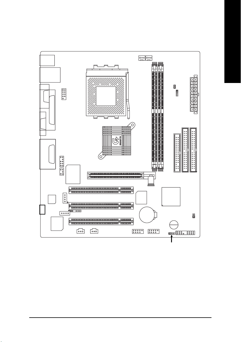
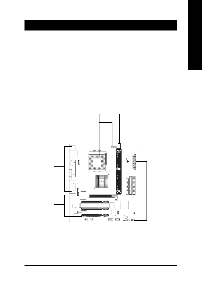
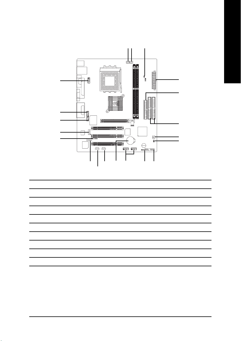
GA-7VKMP / GA-7VKMP-P Motherboard Layout
English
KB_MS
USB
VGA
LINE_OUTMIC_IN
SUR_CEN
-P
COMA
LINE_IN
CODEC
CD_IN
LAN
LPT
F_AUDIO
GAME
AUX_IN
RTL
8100BL
COMB
()
SPDIF
ITE8705F
()
CPU
SYS
FAN
FAN
RAM_LED
CLK_JP
ATX
GA-7VKMP
SOCKET A
VIA KM266
DDR2
BIOS
F_USB1
BATTERY
DDR1
VIA VT8235
BUZZER
F_USB2
AGP
PCI1
PCI2
IR
SPDIF_IN
PCI3
()
FDD
IDE1
F_PANEL
IDE2
CI
PWR_LED
For GA-7VKMP only. For GA-7VKMP-P only. a For GA-7VKMP-SI only.
- 7 -
Introduction
Page 12
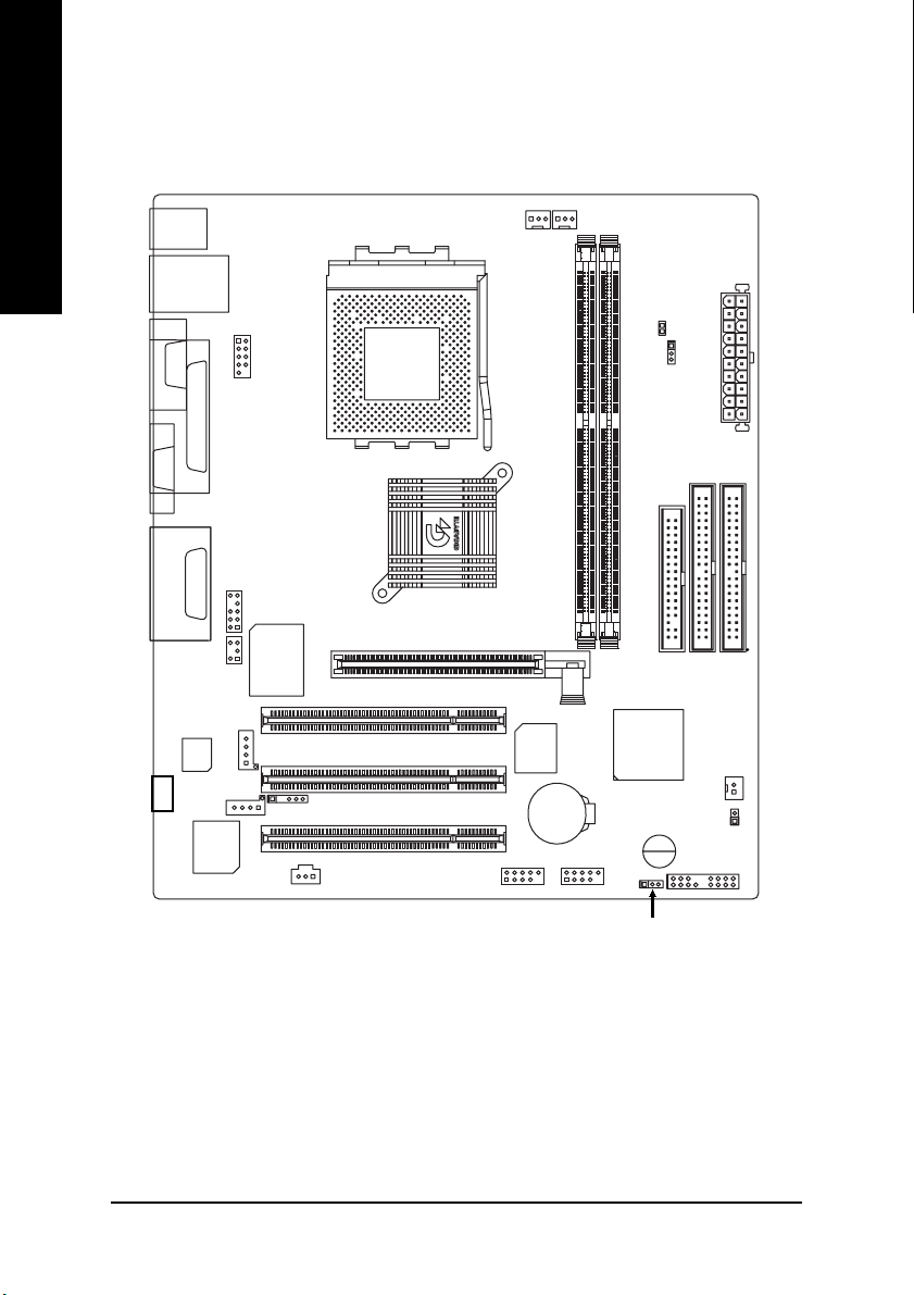
GA-7VKMP-SI Motherboard Layout
English
KB_MS
USB
LAN
CPU
FAN
SYS
FAN
RAM_LED
COMA
VGA
LINE_OUTMIC_IN
LINE_IN
CODEC
-SI
LPT
F_AUDIO
GAME
SUR_CEN
AUX_IN
CD_IN
RTL
8100BL
COMB
ITE8705F
IR
SPDIF
AGP
SOCKET A
VIA KM266
PCI1
PCI2
PCI3
BIOS
BATTERY
F_USB1
GA-7VKMP
DDR1
VIA VT8235
F_USB2
CLK_JP
DDR2
BUZZER
PWR_LED
FDD
IDE1
F_PANEL
ATX
IDE2
S_IRQ
CI
- 8 -GA-7VKMP Series Motherboard
Page 13
Chapter 2 Hardware Installation Process
T o set up your computer, you must complete the following steps:
Step 1 -Set system Jumper (CLK_JP)
Step 2 -Install the Central Processing Unit (CPU)
Step 3 -Install memory modules
Step 4 -Install expansion cards
Step 5 -Connect ribbon cables, cabinet wires and power supply
Step 6 -Setup BIOS software
Step 7 -Install supporting software tools
English
Step 5
Step 4
Step2
Step 3
Step 1
Step 5
- 9 - Hardware Installation Process
Page 14
Step 1: Install the Central Processing Unit (CPU)
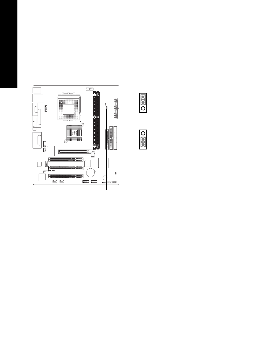
Step 1-1: CPU Speed Setup
English
The system bus frequency can be switched at 100/133MHz and auto by adjusting CLK_JP.
(The frequency ratio depend on CPU.)
CLK_JP
1
1-2 close: 100MHz
2-3 close: 133MHz
1
- 10 -GA-7VKMP Series Motherboard
Page 15
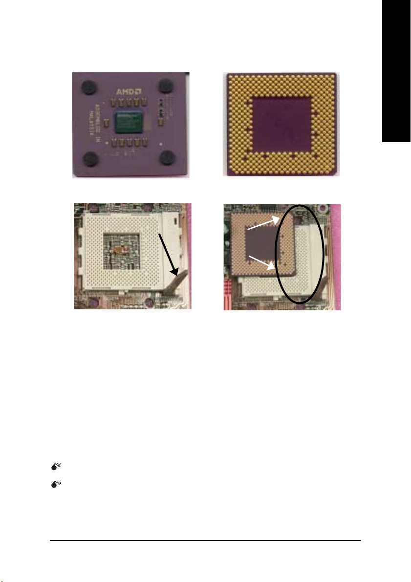
Step 1-2: CPU Installation
English
CPU Top View
Socket Actuation Lever
1. Pull up the CPU socket lever
and up to 90-degree angle.
CPU Bottom View
Pin1 indicator
2. Locate Pin 1 in the socket and look
for a (golden) cut edge on the CPU
upper corner. Then insert the CPU
into the socket.
Please make sure the CPU type is supported by the motherboard.
If you do not match the CPU socket Pin 1 and CPU cut edge well, it will cause
improper installation. Please change the insert orientation.
- 11 - Hardware Installation Process
Page 16
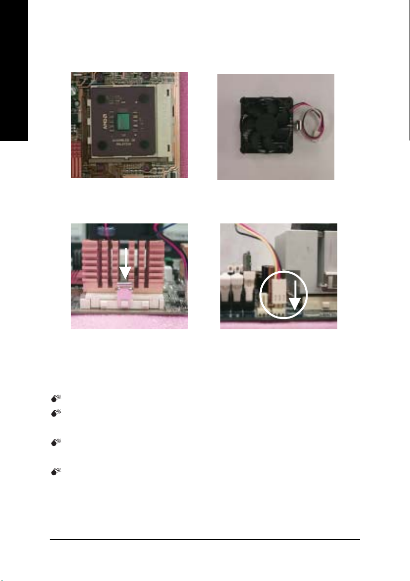
Step 1-3: CPU Heat Sink Installation
English
1. Press down the CPU socket
lever and finish CPU installation.
3. Fasten the heatsink supportingbase onto the CPU socket on the
motherboard.
2. Use qualified fan approved by AMD.
4.Make sure the CPU fan is plugged
to the CPU fan connector, than in-
stall complete.
Please use AMD approved cooling fan.
We recommend you to apply the thermal paste to provide better heat
conduction between your CPU and heatsink.
Make sure the CPU fan power cable is plugged in to the CPU fan connector,
this completes the installation.
Please refer to CPU heat sink user's manual for more detail installation
procedure.
- 12 -GA-7VKMP Series Motherboard
Page 17
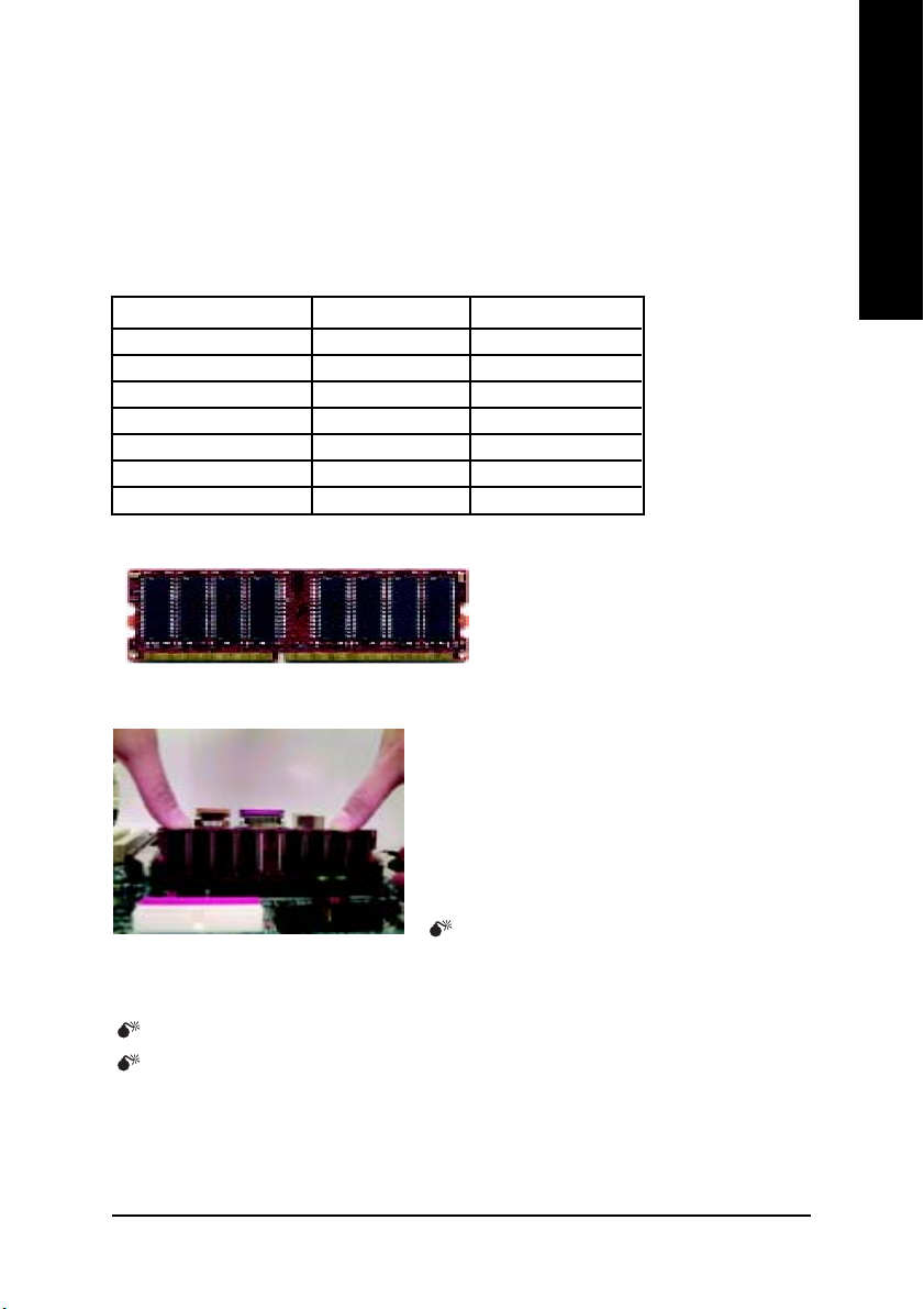
Step 2: Install memory modules
The motherboard has 2 dual inline memory module (DIMM) sockets. The BIOS will automatically
detects memory type and size. To install the memory module, just push it vertically into the DIMM
socket. The DIMM module can only fit in one direction due to the notch. Memory size can vary
between sockets.
Total Memory Sizes With Unbuffered DDR DIMM
Devices used on DIMM 1 DIMM x 64 / x 72 2 DIMMs x 64 / x 72
64 Mbit (2Mx8x4 banks) 128 MBytes 256 MBytes
64 Mbit (1Mx16x4 banks) 32 MBytes 64 MBytes
128 Mbit(4Mx8x4 banks) 256 MBytes 512 MBytes
128 Mbit(2Mx16x4 banks) 64 MBytes 128 MBytes
256 Mbit(8Mx8x4 banks) 512 MBytes 1 GBytes
256 Mbit(4Mx16x4 banks) 128 MBytes 256 MBytes
512 Mbit(8Mx16x4 banks) 256 MBytes 512 MBytes
DDR
English
1. The DIMM socket has a notch, so the DIMM
memory module can only fit in one direction.
2. Insert the DIMM memory module vertically into the
DIMM socket. Then push it down.
3. Close the plastic clip at both edges of the DIMM
sockets to lock the DIMM module.
Reverse the installation steps when you wish to
remove the DIMM module.
When RAM_LED is ON, you do not install / remove DDR from socket.
Please note that the DIMM module can only fit in one direction due to the two
notches. Wrong orientation will cause improper installation. Please change
the insert orientation.
- 13 - Hardware Installation Process
Page 18
DDR Introduction
a high performance and cost-effective solution that allows easy adoption for memory vendors, OEMs
English
and system integrators.
SDRAM infrastructure, yet makes awesome advances in solving the system performance bottleneck
by doubling the memory bandwidth. DDR SDRAM will offer a superior solution and migration path from
existing SDRAM designs due to its availability, pricing and overall market support. PC2100 DDR
memory (DDR266) doubles the data rate through reading and writing at both the rising and falling edge
of the clock, achieving data bandwidth 2X greater than PC133 when running with the same DRAM
clock frequency. With peak bandwidth of 2.1GB per second, DDR memory enables system OEMs to
build high performance and low latency DRAM subsystems that are suitable for servers, workstations,
high-end PC's and value desktop SMA systems.
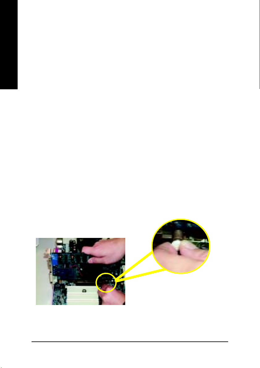
Step 3: Install expansion cards
1. Read the related expansion card’s instruction document before install the expansion card into the
2. Remove your computer’s chassis cover, necessary screws and slot bracket from the computer.
3. Press the expansion card firmly into expansion slot in motherboard.
4. Be sure the metal contacts on the card are indeed seated in the slot.
5. Replace the screw to secure the slot bracket of the expansion card.
6. Replace your computer’s chassis cover.
7. Power on the computer, if necessary, setup BIOS utility of expansion card from BIOS.
8. Install related driver from the operating system.
Established on the existing SDRAM industry infrastructure, DDR (Double Data Rate) memory is
DDR memory is a sensible evolutionary solution for the PC industry that builds on the existing
computer.
AGP Card
Please carefully pull out the small whitedrawable bar at the end of the AGP slot when
you try to install/ uninstall the AGP card. Please
align the AGP card to the onboard AGP slot
and press firmly down on the slot. Make sure
your AGP card is locked by the small whitedrawable bar.
- 14 -GA-7VKMP Series Motherboard
Page 19
Step 4: Connect ribbon cables, cabinet wires and
power supply
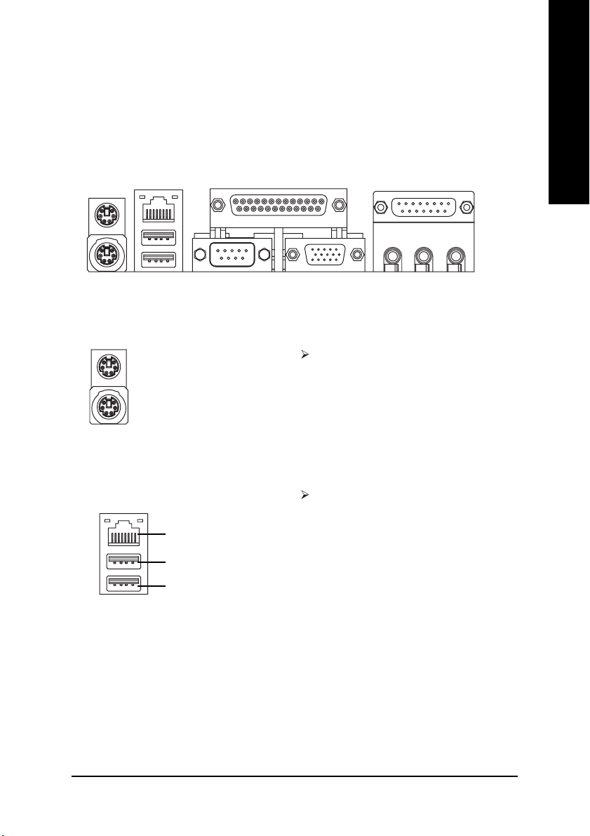
Step 4-1 : I/O Back Panel Introduction
English
X
XX
X PS/2 Keyboard and PS/2 Mouse Connector
XX
YZ [
PS/2 Mouse Connector
(6 pin Female)
PS/2 Keyboard Connector
(6 pin Female)
This connector supports standard PS/2 keyboard and PS/2 mouse.
Y USB & LAN Connector
Before you connect your device(s) into USB
connector(s), please make sure your device(s)
LAN
USB 0
USB 1
such as USB keyboard, mouse, scanner, zip,
speaker...etc. Have a standard USB interface.
Also make sure your OS supports USB controller.
If your OS does not support USB controller, please
contact OS vendor for possible patch or driver
upgrade. For more information please contact your
OS or device(s) vendors.
\
- 15 - Hardware Installation Process
Page 20
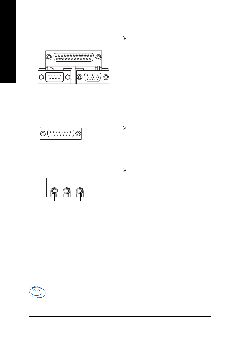
Z Parallel Port and VGA Port / COMA Port
English
[ Game / MIDI Ports
\ Audio Connectors
(Front Speaker
Parallel Port
(25 pin Female)
COMA VGA
Serial Port
(9 pin Male)
VGA Port
(15 pin Female)
Joystick/ MIDI (15 pin Female)
Line Out
(a)
(Rear Speaker
MIC In
(Center and Subwoofer
)
Line In
(a)
)
This motherboard sutports 1 standard COM
port,1 VGA port and 1 LPT port. Device like
printer can be connected to LPT port; mouse
and modem etc. can be connected to COM
port.
This connector supports joystick, MIDI keyboard
and other relate audio devices.
After install onboard audio driver, you may connect speaker to Line Out jack, microphone to
MIC In jack. Device like CD-ROM,walkman
etc. can be connected to Line-In jack.
Please note:
Y ou are able to use 2-/4-/6-channel audio fea-
(a)
)
(a)
ture by S/W selection.
If you want to enable 6-channel function, you
have 2 choose for hardware connection.
Method1:
Connect "Front Speaker" to "Line Out"
Connect "Rear Speaker" to "Line In"
Connect "Center and Subwoofer" to "MIC Out ".
Method2:
You can refer to page 21, and contact your
nearest dealer for optional SUR_CEN cable.
If you want the detail information for 2-/4-/6-channel audio setup
installation, please refer to page 60.
For GA-7VKMP only. For GA-7VKMP-P only. a For GA-7VKMP-SI only.
- 16 -GA-7VKMP Series Motherboard
** Only for GA-7VKMP-SI.
Page 21
Step 4-2 : Connectors Introduction
English
2
6
16
9
(a)
12
10
15
1) CPU_FAN
2) SYS_FAN
3) ATX
4) FDD
5) IDE1 / IDE2
6) RAM_LED
7) F_PANEL
8) PWR_LED
9) F_AUDIO
10) AUX_IN
11 17
()
14
(a)
13
19
718
11) CD_IN
12) SUR_CEN
13) SPDIF
14) SPDIF_IN
(a )
(a)
()
15) IR
16) COMB
17) F_USB1 / F_USB2
18) S_IRQ
(a)
19) BATTERY
20) CI
18
20
3
4
5
(a)
For GA-7VKMP only. For GA-7VKMP-P only. a For GA-7VKMP-SI only.
- 17 - Hardware Installation Process
Page 22
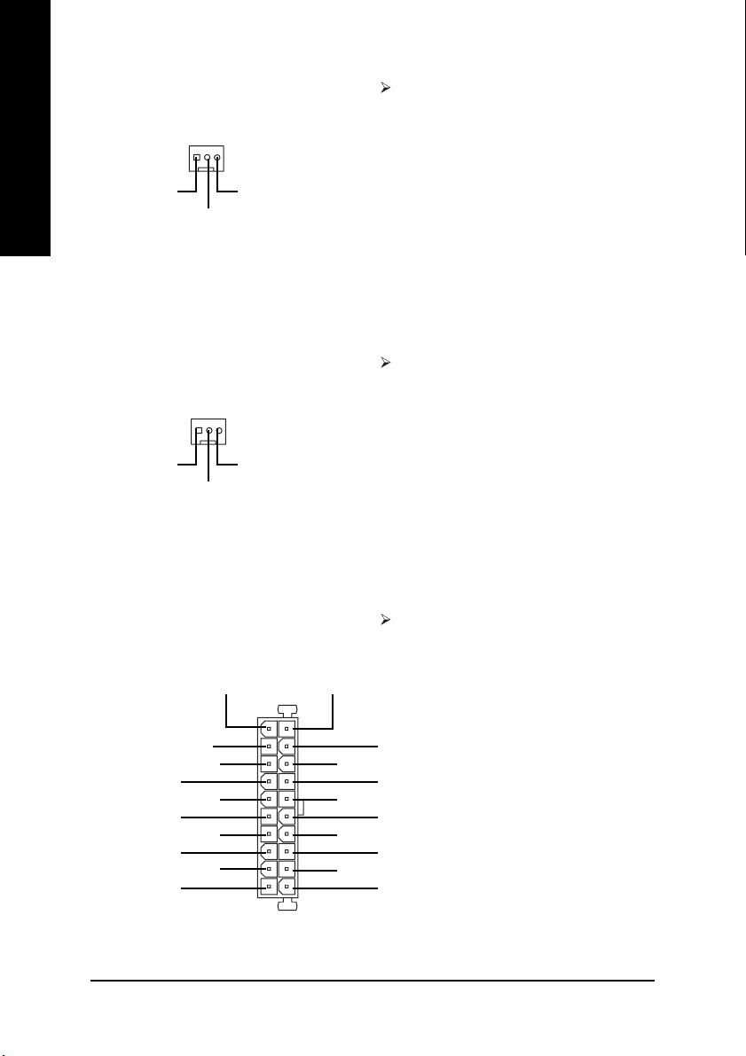
1) CPU_FAN (CPU Fan Connector) Please note, a proper installation of the CPU
English
1
GND
+12V/Control
Sense
cooler is essential to prevent the CPU from
running under abnormal condition or damaged
by overheating. The CPU fan connector
supports Max. current up to 600 mA.
2) SYS_FAN (System Fan Connector)
1
GND
+12V/Control
Sense
3) ATX (ATX Power)
+12V
5V SB (Stand by +5V)
Power Good
GND
VCC
GND
VCC
GND
3.3V
3.3V
20
1
VCC
VCC
-5V
GND
GND
GND
PS-ON(Soft On/Off)
GND
-12V
3.3V
This connector allows you to link with the
cooling fan on the system case to lower the
system temperature.
AC power cord should only be connected to
your power supply unit after A TX power cable
and other related devices are firmly connected
to the motherboard.
- 18 -GA-7VKMP Series Motherboard
Page 23
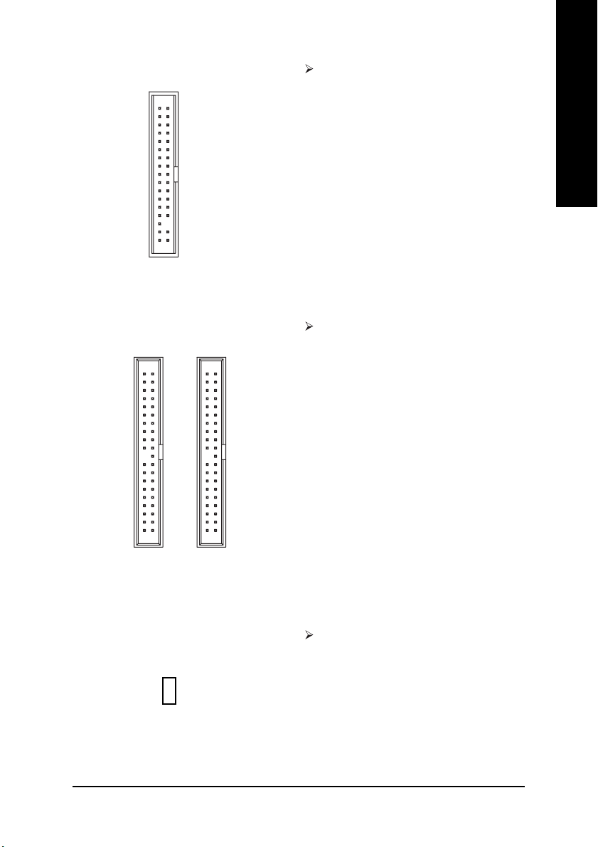
4) FDD (Floppy Connector)
FDD
1
Please connect the floppy drive ribbon cables
to FDD. It supports 360K, 1.2M, 720K, 1.44M
and 2.88M bytes floppy disk types.
The red stripe of the ribbon cable must be the
same side with the Pin1.
English
5) IDE1 / IDE2 (IDE1 / IDE2 Connector)
IDE1
IDE2
1
1
Important Notice:
Please connect first hard disk to IDE1 and
connect CD-ROM to IDE2.
The red stripe of the ribbon cable must be the
same side with the Pin1.
6) RAM_LED Do not remove memory modules while
DIMM LED is on. It might cause short or other
+
_
unexpected damages due to the 2.5V stand
by voltage. Remove memory modules only
when AC Power cord is disconnected.
- 19 - Hardware Installation Process
Page 24
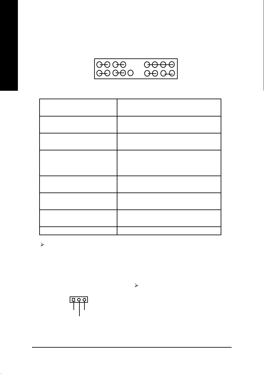
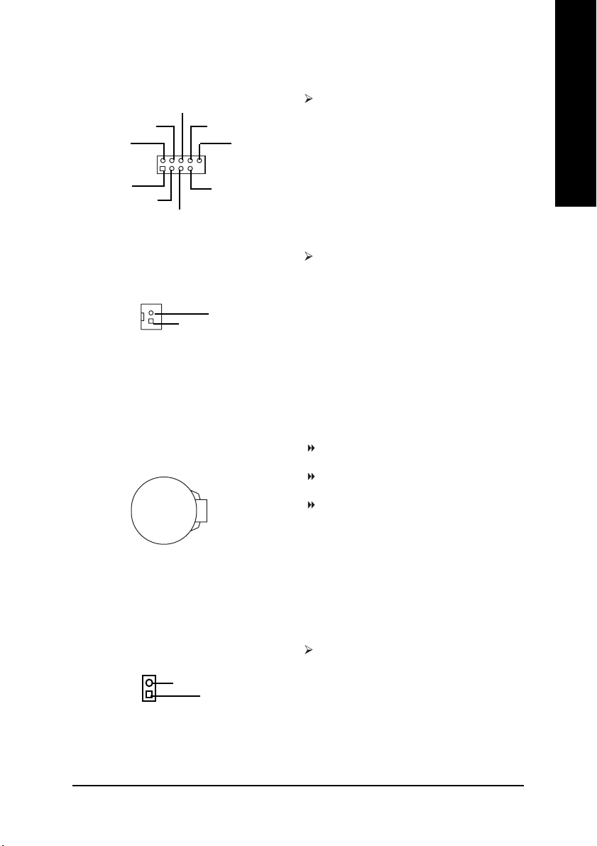
7) F_PANEL (2x10 pins connector)
English
MPD+
MPD-
PW-
PW+
1
1
2
119
1
HD+
GN (Green Switch) Open: Normal Operation
GD (Green LED) Pin 1: LED anode(+)
HD (IDE Hard Disk Active LED) Pin 1: LED anode(+)
SPK (Speaker Connector) Pin 1: VCC(+)
RST (Reset Switch) Open: Normal Operation
PW (Soft Power Connector) Open: Normal Operation
MPD (Message LED/Power/ Pin 1: LED anode(+)
Sleep LED) Pin 2: LED cathode(-)
NC NC
1
HD-
NC
RST-
RST+
Close: Entering Green Mode
Pin 2: LED cathode(-)
Pin 2: LED cathode(-)
Pin 2- Pin 3: NC
Pin 4: Data(-)
Close: Reset Hardware System
Close: Power On/Off
SPK+
1
1
GD+
NC
GD-
NC
1
GN+
SPK-
20
GN-
Please connect the power LED, PC speaker, reset switch and power switch etc. of your
chassis front panel to the F_PANEL connector according to the pin assignment above.
8) PWR_LED
1
MPD+
MPD-
MPD-
PWR_LED is connect with the system power
indicator to indicate whether the system is
on/off. It will blink when the system enters
suspend mode.
If you use dual color LED, Power LED will
turn to another color.
- 20 -GA-7VKMP Series Motherboard
Page 25
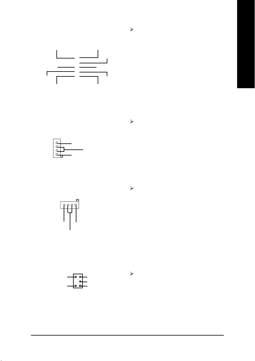
9) F_AUDIO (Front Audio Connector)
Rear Audio (L)
Rear Audio (R)
GND
2
910
1
Front Audio (L)
Reserved
Front Audio (R)
REFPOWER
MIC
If you want to use Front Audio connector, you
must remove 5-6, 9-10 Jumper. In order to
utilize the front audio header, your chassis must
have front audio connector. Also please make
sure the pin assigment on the cable is the same
as the pin assigment on the MB header. T o find
out if the chassis you are buying support front
audio connector, please contact your dealer.
English
10) AUX_IN (AUX In Connector)
AUX-R
1
GND
AUX-L
11) CD_IN (CD In Connector)
1
CD-LCD-R
GND
12) SUR_CEN (Surround Center Connector)
BASS_OUT
SUR OUT(R)
CENTER_OUT
GND
SUR OUT(L)
12
Connect other device (such as PCI TV Tunner
audio out) to the connector.
Connect CD-ROM or DVD-ROM audio out to
the connector.
(a)
Please contact your nearest dealer for optional
SUR_CEN cable.
For GA-7VKMP only. For GA-7VKMP-P only. a For GA-7VKMP-SI only.
- 21 - Hardware Installation Process
Page 26

13) SPDIF (SPDIF Out)
English
GND
1
SPDIF Out
(a) The SPDIF output is capable of providing
digital audio to external speakers or
compressed AC3 data to an external Dolby
Digital Decoder. Use this feature only when
your stereo system has digital input function.
VCC
6 Channel output : A "S/PDIF output" connector
is available on the motherboard. Be careful
with the polarity of the SPDIF out connector.
Check the pin assignment carefully while you
connect the SPDIF out cable, incorrect connection between the cable and connector will make
the device unable to work or even damage it.
For optional SPDIF out cable, please contact
your local dealer.
14) SPDIF_IN (SPDIF In)
1
GND
SPDIF In
15) IR
1
VCC(+5V)
IR Data Output
IR Data Input
GND
16) COMB (COMB Port)
12
910
RXD2
DSR2
NC
DCD2
TXD2
GND
RTS2
RI2
( ) Use this feature only when your device has
digital output function. Be careful with the polarity of the SPDIF in connector. Check the pin
assignment carefully while you connect the
SPDIF in cable, incorrect connection between
VCC
DTR2
CTS2
the cable and connector will make the device
unable to work or even damage it. For optional
SPDIF in cable, please contact your local dealer.
Be careful with the polarity of the IR connector.
Check the pin assignment carefully while you
connect the IR cable, incorrect connection
between the cable and connector will make the
device unable to work or even damage it. For
optional IR cable, please contact your local
dealer.
Be careful with the polarity of the COMB
connector. Check the pin assignment carefully
while you connect the COMB cable, incorrect
connection between the cable and connector
will make the device unable to work or even
damage it. For optional COMB cable, please
contact your local dealer.
For GA-7VKMP only. For GA-7VKMP-P only. a For GA-7VKMP-SI only.
- 22 -GA-7VKMP Series Motherboard
Page 27
17) F_USB1 / F_USB2 (Front USB Connector)
English
USB Dy+
USB Dy-
Power
GND
USB Over
Current
1
Power
GND
USB Dx-
USB Dx+
18) S_IRQ (Serial IRQ Connector)
Signal
GND
1
19) BATTERY (Battery)
+
(a)
Be careful with the polarity of the front panel
USB connector. Check the pin assignment while
you connect the front panel USB cable. Please
contact your nearest dealer for optional front
USB cable.
This connector is for special design, for
example: PCMCIA add on card. Be careful
with the polarity of the Serial IRQ connector.
Check the pin assignment carefully while you
connect the Serial IRQ cable, incorrect
connection between the cable and connector
will make the device unable to work or even
damage it. For optional Serial IRQ cable, please
contact your local dealer.
CAUTION
Danger of explosion if battery is incorrectly
replaced.
Replace only with the same or equivalent type
recommended by the manufacturer.
Dispose of used batteries according to the
manufacturer's instructions.
If you want to erase CMOS...
1. Turn OFF the computer and unplug the power cord.
2. Remove the battery, wait for 30 second.
3. Re-install the battery.
4. Plug the power cord and turn ON the computer.
20) CI (CASE OPEN)
1
GND
Signal
This 2 pin connector allows your system to
enable or disable the system alarm if the system
case begin remove.
For GA-7VKMP only. For GA-7VKMP-P only. a For GA-7VKMP-SI only.
- 23 - Hardware Installation Process
Page 28

English
- 24 -GA-7VKMP Series Motherboard
Page 29

Chapter 3 BIOS Setup
BIOS Setup is an overview of the BIOS Setup Program. The program that allows users to modify the
basic system configuration. This type of information is stored in battery-backed CM OS RAM so that it
retains the Setup information when the power is turned off.
English
ENTERING
Powering ON the computer and pressing <Del> immediately will allow y ou to enter Setup. If you require
more advanced BIOS settings, please go to "Advanced BIOS" setting menu. To enter Advanced BIOS
setting menu, press "Ctrl+F1" key on the BIOS screen.
CONTROL
< > Move to previous item
< > Move to next item
< > Move to the item in the left hand
< > Mov e to the item in the right hand
<Enter> Select Item
<Esc> Main Menu - Quit and not save changes into CM OS Status Page Setup Menu and
<+/PgUp> Increase the numeric value or make changes
<-/PgDn> Decrease the numeric value or make changes
<F1> General help, only for Status Page Setup Menu and Option Page Setup Menu
<F2> Item Help
<F3> Reserved
<F4> Reserved
<F5> Restore the previous C MOS value from CM OS, only for Option Page Setup Menu
<F6> Load the file-safe default CMOS v alue from BIOS default table
<F7> Load the Optimized Defaults
<F8> Q-Flash function
<F9> Reserved
<F10> Save all the CMOS changes, only for Main Menu
SETUP
KEYS
Option Page Setup Menu - Exit current page and return to Main Menu
- 25 - BIOS Setup
Page 30

GETTING HELP
The on-line description of the highlighted setup function is displayed at the bottom of the screen.
English
Press F1 to pop up a small help window that describes the appropriate keys to use and the possible
selections for the highlighted item. To exit the Help Window press <Esc>.
The Main Menu (For example: BIOS Ver. : F1h)
Once you enter AMI BIOS C MOS Setup Utility, the Main Menu (Figure 1) w ill appear on the screen.
The Main Menu allows y ou to select from eight setup functions and two ex it choices. Use arrow key s to
select among the items and press <Enter> to accept or enter the sub-menu.
Main Menu
Status Page Setup Menu / Option Page Setup Menu
AMIBIOS SIMPLE SETUP UTILITY - VERSION 2.00
(C) 2001 American Megatrends, Inc. All Rights Reserved
STANDARD CMOS SETUP INTEGRATED PERIPHERALS
BIOS FEATURES SETUP HARDWARE MONITOR & MISC SETUP
CHIPSET FEATURES SETUP SUPERVISOR PASSWORD
POWER MANAGEMENT SETUP USER PASSWORD
PNP / PCI CONFIGURATION IDE HDD AUTO DETECTION
LOAD FAIL-SAFE DEFAULTS SAVE & EXIT SETUP
LOAD OPTIMIZED DEFAULTS EXIT WITHOUT SAVING
ESC: Quit hifg: Select Item F5: Old Values F6: Fail-Safe Values
F7: Optimized Values F8: Q-Flash Utility F10:Save & Exit
Time, Date, Hard Disk Type...
Figure 1: Main Menu
l Standard CMOS Setup
This setup page includes all the items in standard compatible BIOS.
l BIOS Features Setup
This setup page includes a ll the adjustable items of AMI special en hanced fea tures.
l Chipset Features Setup
This setup page includes all the adjustable items of chipset special features.
- 26 -GA-7VKMP Series Motherboard
Page 31

l Power Management Setup
This setup page includes all the adjustable items of Green function features.
l PNP/PCI Configuration
This setup page includes al l the adjustable configurations of PCI & Pn P ISA resources.
l Load Fail-Safe Defaults
Load Fail-Safe Defaults option loads preset sy stem parameter values to set the system in its
most stable configurations.
l Load Optimized Defaults
Load Optimized Defaults option loads preset system parameter values to set the system in its
highest performance configurations.
l Integrated Peripherals
This setup page includes all onboard peripherals.
l Hardware Monitor & MISC Setup
This setup page is auto detect fan and temperature status.
l Supervisor Password
Set Change or dis able passw ord. It allow s you to limit access to the sy stem and/or BIOS
setup.
l User Password
Set Change or dis able passw ord. It allow s you to limit access to the sy stem.
l IDE HDD Auto Detection
Automatically con figure hard disk param eters.
l Save & Exit Setup
Save C MOS value settings to CM OS and exit setup.
l Exit Without Saving
Abandon all CM OS value changes and exit setup.
English
- 27 - BIOS Setup
Page 32

Standard CMOS Features
English
System Date : Jul 01 2002 Mon
System Time : 16:10:49
Pri Master : Auto
Pri Slave : Auto
Sec Master : Auto
Sec Slave : Auto
AMIBIOS SETUP - STANDARD CMOS SETUP
( C ) 2001 American Megatrends, Inc. All Rights Reserved
TYPE SIZE CYLS HEAD PRECOMP LANDZ SECTOR MODE
Floppy Drive A : 1.44 MB 3
Floppy Drive B : Not Installed Other Memory : 384 Kb
Virus Protection : Disabled Total Memory : 128 Mb
Date is standard format ESC : Exit
Month : Jan - Dec hi : Select Item
Day : 01- 31 PU / PD / + / - :Modify
Year : 1990 - 2099 (Shift) F2 : Color
1/2
Figure 2: Standard CMOS Setup
Base Memory : 640 Kb
Extended Memory : 127 Mb
Date
The date format is <week>, <month>, <day>, <y ear>.
Week The w eek, from Sun to Sat, determined by the BIOS and is display only
Month The month, Jan. Through Dec.
Day The day, from 1 to 31 (or the maxi mum allowed in the month)
Year The y ear, from 1990 through 2099
Time
The times format in < hour> <minute> <second>. The time is calcu lated b ase on the 24-ho ur
military time clock. For ex ample, 1 p.m. is 13: 00:00.
- 28 -GA-7VKMP Series Motherboard
Page 33

Primary Master, Slave / Secondary Master, Slave
The category identifies the types of hard di sk from drive C to F that has been installed in the
computer. There are two ty pes: auto type, and manual type . Manual ty pe is user-definable; Auto
type w hich will automatically de tect HDD type.
Note that the specifications of your driv e must match with the drive table. The hard disk w ill not
work properly if you enter improp er information for this category.
If you select User Type, related information w ill be asked to enter to the followi ng items. Enter
the information directly from the keyboard and pr ess <Enter>. Such information should be prov ided
in the documentation form your ha rd disk v endor or the system manufacturer.
Cylinder Numbe r of cylinders
Head Number of heads
Precomp Write precomp
Landing Zone Landing zone
Sector Numbe r of sectors
If a hard disk has not been installed select NONE and press <Enter>.
Floppy Drive A / Drive B
The category identifies the types of floppy disk drive A or drive B that has been installed in the
computer.
Not Installed No floppy driv e installed
1/4
1.2MB, 5
720KB, 3
1.44MB, 3
2.88MB, 3
1/2
5.25 inch AT-type high- density driv e; 1.2M byte capacity
(3.5 inch whe n 3 Mode is Enabled).
3.5 inch double-sided dr ive; 720K by te capacity
1/2
3.5 inch double-sided dri ve; 1.44M by te capacity.
1/2
3.5 inch double-sided dri ve; 2.88M by te capacity.
English
Virus Protection
If it is set to enable, the category will flash on the screen w hen there is any attempt to wri te to
the boot sector or partition table of the hard disk drive. The sy stem will halt and the followi ng error
message will a ppear in the mean time. You can run anti-virus program to locate the problem.
Disabled No w arning message to appear when anything attempts to access the boot
sector or hard disk pa rtition table. (Default Value)
Enabled Ac tiv ate a utomaticall y whe n the sy stem boots up causi ng a w arning
message to appear w hen anything attempts to access the boot sector or
hard disk partition table.
- 29 - BIOS Setup
Page 34

English
Memory
The category is display-only which is determined by POST (Power O n Self Test) of the BIOS.
-- Base Memory
The POST of the BIOS will determine the amount of base (or conventional) memory installed
in the system.
The v alue of the base me mory is typically 512K for sy stems with 512K memory installed
on the motherboard, or 640K for s ystems w ith 640 K or mo re memor y in stalled on the
motherboard.
-- Other Memory
This refers to the memory located in the 640K to 1024K address space. This is memory that
can be used for different applications.
DOS uses this area to load device drivers to keep as much base memory free for application
programs. Most use for this area is Shadow RAM.
-- Extended Memory
The BIOS determines how much extended me mory is present during the POST.
This is the amount of memory located abov e 1MB in the CPU's memory address map.
- 30 -GA-7VKMP Series Motherboard
Page 35

BIOS Features Setup
AMIBIOS SETUP - BIOS FEATURES SETUP
( C ) 2001 American Megatrends, Inc. All Rights Reserved
BIOS Flash Protection : Auto
1st Boot Device : Flo ppy
2nd Boot Dev ice :Disabled
3rd Boot Dev ice : Disabled
Floppy Drive Seek : Disabled
BootUp Num-Lock : On
Password Check : Setup
S.M.A.R.T. for Hard Disk : Disabled
Interrupt Mode : APIC
Figure 3: BIOS Features Setup
BIOS Flash Protection
This field lets y ou determine the states that flash BIOS.
Auto BIOS enables flash w rite access automatically w hen updating BIOS data/DMI/
ESCD. (Default Value)
Enabled During POST, DMI/ESCD would not be updated. But flash tools can update BIOS
alway s.
ESC: Quit hifg: Select Item
F1 : Help PU/PD/+/- : Modify
F5 : Old Values (Shift)F2: Color
F6 : Fail-Safe F7 : Optimized
F8 : Q-Flash Utility
English
1st / 2nd / 3rd Boot Device
Disabled Disabled this function.
Floppy: 1.44M B 3
BBS-0(Network ): Realtek Boot Agent Select your boot device priori ty by Network.
IDE-0: ST320420A Sel ect your b oot device priority by IDE Dev ice.
USB RMD-FDD: Apacer Handy Drive Select your b oot device priority by USB Dev ice.
Boot order depends on the dev ices you use, for exa mple: Floppy, HDD, C D-ROM...
1/2
Select your boot device prior ity by Floppy .
- 31 - BIOS Setup
Page 36

English
Floppy Drive Seek
During POST, BIOS will d etermine the floppy disk dr ive installed is 80 tracks. 720K, 1.2 M and
1.44M are all 80 tracks.
Enabled BIOS searches for floppy disk driv e to determine it is 80 tracks. Note that BIOS
can not tell from 720K, 1.2M or 1 .44M drive type as they are all 80 tracks.
Disabled BIOS will not search for the type of floppy disk drive by track number. Note that
there will not be any warning messa ge if the drive ins talled is 360K.
(Default value)
BootUp Num-Lock
Off When bootup, setting keypad i s arrow key s.
On When bootup, setting keyp ad is number key s. (Default v alue)
Password Check
Please refer to the detail on page 49.
Setup The user must enter correct passw ord in order to access BIOS setup utility.
(Default Value)
Alw ay s The u ser must enter correct passw ord in order to access the sy stem and/or
BIOS Setup.
S.M.A.R.T. for Hard Disks
Enabled Enabl e HDD S.M.A.R.T. Capability.
Disabled Disable HDD S.M.A.R.T. Capability. (Default value)
APIC Interrupt Mode
APIC Through IOAPIC generate more IRQ for system use. ( Default Value)
PIC Use AT standard IRQ controllers to generate IRQ.
When you alread y have IOAPIC enable sy stem and want to upgrade the system please note,
since running an IOAPIC enabled OS (like Windows NT, Window s 2000, Windows XP...) system
with none IOAPIC HW support will cause the system to hang. Follow ing are some situations users
might run into: 1.An IOAPIC enabled OS and change the BIOS setting from IOAPIC to PIC, this will
cause your sy stem to hang.
- 32 -GA-7VKMP Series Motherboard
Page 37

Chipset Features Setup
We would not suggest you change the chipset default setting unless you really need it.
AMIBIOS SETUP - CHIPSET FEATURES SETUP
( C ) 2001 American Megatrends, Inc. All Rights Reserved
Configure SDRAM by SPD : Enabled
SDRAM Frequency : Auto
SDRAM CAS# Latency : 2.5
SDRAM Command Rate : 2T Command
AGP Mode : 4X
AGP Comp. Driving : Auto
Manual AGP Comp. Driving : DA
AGP Fast Write : Disabled
AGP Aperture Size : 64MB
AGP Read Synchronization : Disabled
PCI Delay Transaction : Disabled
USB Controller : 6 USB Ports
USB 1.1 Legacy Support : Disabled
USB 1.1 64/60 Emulation : Disabled
Figure 4: Chipset Features Setup
ESC : Quit hifg : Select Item
F1 : Help PU/PD/+/- : Modify
F5 : Old Values (Shift)F2 : Color
F6 : Fail-Safe F7 : Optimized
F8 : Q-Flash Utility
English
Configure SDRAM by SPD
Disabled Disable Configure SDRAM by SPD.
Enabled Enabl e Configure SDRAM by SPD. (Default Value)
SDRAM Frequency
200MHz Set SDRAM Frequency to 200MHz.
266MHz Set SDRAM Frequency to 266MHz.
Auto Set SDRAM Frequency to Auto. (Default Value)
SDRAM CAS# Latency
This item will be available w hen "Configure SDRAM by SPD" set to Disabled.
2.5 For Slower SDRAM DIMM module. ( Default Value)
2 For Fastest SDRAM DIMM module.
- 33 - BIOS Setup
Page 38

English
SDRAM Command Rate
2T Command Set SDRAM Command Rate to 2T Command. (Default Value)
1T Command Set SDRAM Command Rate to 1T Command.
AGP Mode
4X Set AGP Mode to 4X. (Default Value)
2X Set AGP Mode to 2X.
1X Set AGP Mode to 1X.
AGP Comp. Driving
Manual Set AGP Comp. Driv ing to Manual.
Auto Set AGP Comp. Driving to Auto. (Default Value)
If AGP Comp. Driving is Manual.
Manual AGP Comp. Driving : 00~FF
Manual AGP Comp. Driving
If "AGP Comp. Driv ing" set to "M anual", this item can be set : 00 ~ FF
AGP Fast Write
Disabled Disable AGP Fast Write. (Default Value)
Enabled Enable AGP Fast Write.
AGP Aperture Size
256MB Set AGP Aperture Size to 256 MB.
128MB Set AGP Aperture Size to 128 MB.
64MB Set AGP Aperture Size to 64 MB. ( Default Value)
32MB Set AGP Aperture Size to 32 MB.
16MB Set AGP Aperture Size to 16 MB.
8MB Set AGP Aperture Size to 8 MB.
4MB Set AGP Aperture Size to 4 MB.
- 34 -GA-7VKMP Series Motherboard
Page 39

AGP Read Synchronization
Disabled Disable AGP Rea d Synchronization. (Default Value)
Enabled Enable AGP Read Sy nchronization.
PCI Delay Transaction
Disabled Disable PCI Delay Trans action.(Default Value)
Enabled Enabl e PCI Delay Transac tion.
USB Controller
Disabled Disable USB Controller function.
2 USB ports Enable 2 USB p orts.
4 USB ports Enable 4 USB p orts.
6 USB ports Enable 6 USB ports. (Default Value)
USB 1.1 Legacy Support
Disabled Disable USB 1. 1 Legacy Support Function. (Default Value)
No Mice Set USB 1.1 Legacy Support without mouse.
All Device Set USB 1.1 Legacy Support with all deveces.
USB 1.1 64/60 Emulation
Disabled Disable this Function. (Default Value)
Enabled To use USB mouse under Win NT envi ronment, set USB Legacy Support to
KB/Mouse/FDD and USB P ort 64/60 Emulation to enabled.
English
- 35 - BIOS Setup
Page 40

Power Management Setup
English
ACPI Standby State : S1/POS
Power LED in S1 State : Blinking
USB Dev. Wakeup From S3 : Disabled
Suspend Time Out (Min.) : Disabled
IRQ 3 : Monitor
IRQ 4 : Monitor
IRQ 5 : Ignore
IRQ 7 : Monitor
IRQ 9 : Ignore
IRQ 10 : Ignore
IRQ 11 : Ignore
IRQ 13 : Ignore
IRQ 14 : Monitor
IRQ 15 : Ignore
Soft-Off by Power Bu tton : Instant off
AC Back Function : Soft-Off
Modem Ring/Wake On Lan : Enabled
PME Event Wake Up : Enabled
Keyboard Wakeup From : S1(Suspend)
PS/2 Mouse Wakeup From : S1(Suspend)
AMIBIOS SETUP - POWER MANAGEMENT SETUP
( C ) 2001 American Megatrends, Inc. All Rights Reserved
Resume On RTC Alarm : Disabled
RTC Alarm Date : 15
RTC Alarm Hour : 12
RTC Alarm Minute : 30
RTC Alarm Second : 30
ESC: Quit hifg: Select Item
F1 : Help PU/PD/+/- : Modify
F5 : Old Values (Shift)F2: Color
F6 : Fail-Safe F7 : Optimized
F8 : Q-Flash Utility
Figure 5: Power Management Setup
ACPI Standby State
S1/POS Set ACPI standby state to S1. (Default Value)
S3/STR Set ACPI standby state to S3.
Power LED in S1 state
Blinking In standby mode (S1), pow er LED wil l blink. (Default Value)
Dual/OFF In standby mode (S1):
a. If use single color LED, pow er LED w ill turn off.
b. If use dual color LED, power LED will turn to another color.
- 36 -GA-7VKMP Series Motherboard
Page 41

USB Dev. Wakeup From S3
Disabled Disable USB Dev Wakeup From S3. (Default Value)
Enabled Enabl e USB Dev Wakeup From S3.
Suspend Time Out (Min.)
Disabled Disable Suspend Time Out Function. (Default Value)
1 Enable Suspend Time Ou t after 1min.
2 Enable Suspend Time Ou t after 2mins.
4 Enable Suspend Time Ou t after 4mins.
8 Enable Suspend Time Ou t after 8mins.
10 Enable Suspend Time Out after 10mins.
20 Enable Suspend Time Out after 20mins.
30 Enable Suspend Time Out after 30mins.
40 Enable Suspend Time Out after 40mins.
50 Enable Suspend Time Out after 50mins.
60 Enable Suspend Time Out after 60mins.
IRQ 3~IRQ15
Ignore Ignore IRQ3 ~IRQ15.
Monitor Monitor IRQ3~IRQ15.
English
Soft-Off Power Button
Instant off The user press the power button once, he c an turn off the sy stem.
(Default Value)
Suspend The user press the power button once, then he can enter suspend mode.
AC Back Function
Soft-Off Alway s in Off state w hen AC back. (Default value)
Full-On Alw ay s pow er on the system w hen AC back.
Memory Sy stem power on depend s on the status before AC lost.
Modem Ring/Wake On LAN
Disabled Disable Modem Ring On / Wake On LAN function.
Enabled The M odem Ring / LAN wake up will b ring the sy stem out of soft-off or
suspend state if this option is set "Enabled". ( Default Value)
- 37 - BIOS Setup
Page 42

English
PME Event Wake Up
Disabled Disable PME Ev ent Wake Up.
Enabled Enabl ed PME Event Wake Up. (Default Value)
Keyboard Wakeup From
S1(Suspend) Keyboard is a ble to Wakeup the sy stem from S1(Suspend) state.
(Default value)
S1/S3 Keybo ard is able to Wakeup the sy stem from S1/S3 state.
S1/S3/S4/S5 Keyboard is a ble to Wakeup the sy stem from S1/S3/S4/S5 state.
PS/2 Mouse Wakeup From
S1(Suspend) PS/2 Mouse is able to Wakeup the sy stem from S1(Suspend) s tate.
(Default value)
S1/S3 PS/2 Mouse is a ble to Wakeup the sy stem from S1/S3 state.
S1/S3/S4/S5 PS/2 Mouse is able to Wakeup the sy stem from S1/S3/S4/S5 s tate.
Resume On RTC Alarm
You can set "Resume On RTC Alarm" item to enabled and key in Data/time to pow er on system.
Disabled Disable this function. (Default Value)
Enabled Enable alarm function to POWER ON sy stem.
If RTC Alarm Lead To Power On is Enabled.
- RTC Alarm Date : Ev eryday , 1~31
- RTC Alarm Hour : 0~23
- RTC Alarm Minute : 0~59
- RTC Alarm Second : 0~59
- 38 -GA-7VKMP Series Motherboard
Page 43

PNP/PCI Configuration
AMIBIOS SETUP - PNP/PCI CONFIGURATION
( C ) 2001 American Megatrends, Inc. All Rights Reserved
OnChip VGA Frame Buffer : 32MB
VGA Boot From : AGP
PCI Slot 1 IRQ Priority : A uto
PCI Slot 2 IRQ Priority : A uto
PCI Slot 3 IRQ Priority : A uto
Realtek LAN ROM initial : Yes
ESC: Quit hifg: Select Item
F1 : Help PU/PD/+/- : Modify
F5 : Old Values (Shift)F2: Color
F6 : Fail-Safe F7 : Optimized
F8 : Q-Flash Utility
Figure 6: PNP/PCI Configuration
OnChip VGA Frame Buffer
None Disable this function.
8MB Set OnChip VGA Frame B uffer to 8MB.
16MB Set OnChip VGA Frame Buffer to 16MB.
32MB Set OnChip VG A Frame Buffer to 32MB. (Default Value)
English
VGA Boot From
PCI Set VGA Boot from PCI VGA Card.
AGP Set VGA Boot from AGP VGA Card. ( Default Value)
- 39 - BIOS Setup
Page 44

English
PCI Slot 1, 2, 3 IRQ Priority
Auto The sy stem will reserv ed a free IRQ for PCI slot 1, 2, 3 device . (Default Value)
3 The system wi ll reserv ed IRQ3 for PCI slot 1, 2, 3 dev ice if no legacy
ISA device using IRQ3.
4 The system wi ll reserv ed IRQ4 for PCI slot 1, 2, 3 dev ice if no legacy
ISA device using IRQ4.
5 The system wi ll reserv ed IRQ5 for PCI slot 1, 2, 3 dev ice if no legacy
ISA device using IRQ5.
7 The system wi ll reserv ed IRQ7 for PCI slot 1, 2, 3 dev ice if no legacy
ISA device using IRQ7.
10 The system wil l reserv ed IRQ10 for PCI slot 1, 2, 3 dev ice if no legacy
ISA device using IRQ10.
111 The system wil l reserv ed IRQ11 for PCI slot 1, 2, 3 dev ice if no legacy
ISA device using IRQ11.
Realtek LAN ROM initial
No Disable Realtek LAN ROM in itial.
Yes Enable Realtek LAN ROM i nitial. (Default Value)
- 40 -GA-7VKMP Series Motherboard
Page 45

Load Fail-Safe Defaults
AMIBIOS SIMPLE SETUP UTILITY - VERSION 2.00
(C) 2001 American Megatrends, Inc. All Rights Reserved
STANDARD CMOS SETUP INTEGRATED PERIPHERALS
BIOS FEATURES SETUP HARDWARE MONITOR & MISC SETUP
CHIPSET FEATURES SETUP SUPERVISOR PASSWORD
POWER MANAGEMENT SETUP USER PASSWORD
PNP / PCI CONFIGURATION IDE HDD AUTO DETECTION
LOAD FAIL-SAFE DEFAULTS SAVE & EXIT SETUP
LOAD OPTIMIZED DEFAULTS EXIT WITHOUT SAVING
ESC: Quit hifg: Select Item F5: Old Values F6: Fail-Safe Values
F7: Optimized Values F8: Q-Flash Utility F10:Sav e & Exit
Load Fail-Safe Defaults
Fail-Safe defaults contain the most appropriate sy stem parameter value s of to configure
the system to achiev e max imum stability.
Load Fail-Safe Defaults (Y/N) ? N
Load Fail-Safe Defaults
Figure 7: Load Fail-Safe Defaults
English
- 41 - BIOS Setup
Page 46

Load Optimized Defaults
English
STANDARD CMOS SETUP INTEGRATED PERIPHERALS
BIOS FEATURES SETUP HARDWARE MONITOR & MISC SETUP
CHIPSET FEATURES SETUP SUPERVISOR PASSWORD
POWER MANAGEMENT SETUP USER PASSWORD
PNP / PCI CONFIGURATION IDE HDD AUTO DETECTION
LOAD FAIL-SAFE DEFAULTS SAVE & EXIT SETUP
LOAD OPTIMIZED DEFAULTS EXIT WITHOUT SAVING
ESC: Quit hifg: Select Item F5: Old Values F6: Fail-Safe Values
F7: Optimized Values F8: Q-Flash Utility F10:Sav e & Exit
AMIBIOS SIMPLE SETUP UTILITY - VERSION 2.00
(C) 2001 American Megatrends, Inc. All Rights Reserved
Load Optimized Defaults (Y/N) ? N
Load Optimized Defaults
Figure 8: Load Optimized Defaults
Load Optimized Defaults
Optimized defaults contain the most appropriate sy stem parameter val ues to configure
the system to achiev e maximum performance.
- 42 -GA-7VKMP Series Motherboard
Page 47

Integrated Peripherals
AMIBIOS SETUP - INTEGRATED PERIPHERALS
( C ) 2001 American Megatrends, Inc. All Rights Reserved
OnBoard IDE : B oth
IDE1 Conductor Cable : A uto
IDE2 Conductor Cable : A uto
OnBoard FDC : Auto
OnBoard Serial Port 1 : A uto
OnBoard Serial Port 2 : A uto
Serial Port2 Mode : No rmal
OnBoard Parallel Port : Auto
Parallel Port Mode : ECP
Parallel Port IRQ : Auto
Parallel Port DMA : Auto
OnBoard MIDI Port : 300
MIDI Port IRQ : 5
OnBoard Game Port : 201
OnBoard AC’97 Audio : Auto
Onboard Lan Chip : Ena bled
English
ESC: Quit hifg: Select Item
F1 : Help PU/PD/+/- : Modify
F5 : Old Values (Shift)F2: Color
F6 : Fail-Safe F7 : Optimized
F8 : Q-Flash Utility
Figure 9: Integrated Peripherals
OnBoard IDE
Disabled Disable OnBoard IDE.
Primary Only Primary IDE channel is ena bled.
Secondary Only Secondary IDE channel is ena bled.
Both Both Primary & Secondary IDE channel will be enabled. (Default Value)
- 43 - BIOS Setup
Page 48

English
IDE1 Conductor Cable
Auto Will be automatically d etected by BIOS. (Default Value)
ATA66/100/133 Set IDE1 Conductor Cable to ATA66/100/133 (P lease make sure you r IDE
device and cabl e is compatible with ATA66/100/133)
ATA33 Set IDE1 Conductor Cable to ATA33 (Please make sure your IDE dev ice
and cable is compatible with ATA33)
IDE2 Conductor Cable
Auto Will be automatically d etected by BIOS. (Default Value)
ATA66/100/133 Set IDE1 Conductor Cable to ATA66/100. (Pl ease make sure you r IDE
device and cab le is compatible w ith ATA66/100)
ATA33 Set IDE1 Conductor Cable to ATA33. (Please make sure your IDE dev ice
and cable is compatible with ATA33)
On Board FDC
Auto Set On Board FDC to Auto. (Default Value)
Disabled Disable On Board FDC.
Enabled Enabl e On Board FDC.
Onboard Serial Port 1
Auto BIOS will automatically setup the port 1 address. (Default Value)
Disabled Disable onboard Serial port 1.
3F8/COM1 Enabl e onboard Serial po rt 1 and address is 3F8.
2F8/COM2 Enabl e onboard Serial po rt 1 and address is 2F8.
3E8/COM3 Enabl e onboard Serial po rt 1 and address is 3E8.
2E8/COM4 Enabl e onboard Serial po rt 1 and address is 2E8.
Onboard Serial Port 2
Auto BIOS will automatically setup the port 2 address. (Default Value)
Disabled Disable onboard Serial port 2.
3F8/COM1 Enabl e onboard Serial po rt 2 and address is 3F8.
2F8/COM2 Enabl e onboard Serial po rt 2 and address is 2F8.
3E8/COM3 Enabl e onboard Serial po rt 2 and address is 3E8.
2E8/COM4 Enabl e onboard Serial po rt 2 and address is 2E8.
- 44 -GA-7VKMP Series Motherboard
Page 49

Serial Port 2 Mode
Normal Norma l operation. (Default Value)
IrDA Onboar d I/O chip supports IrDA.
ASKIR Onboar d I/O chip supports ASKIR.
OnBoard Parallel port
Auto Set On Board L PT port is Auto. (Default Value)
Disabled Disable On Board LPT port.
378 Enable On Boa rd LPT port and address is 378.
278 Enable On Boa rd LPT port and address is 278.
3BC Enable On Board LPT po rt and address is 3BC.
Parallel Port Mode
Normal Norma l Operation.
EPP Using Parallel port as Enhanced Parallel Port.
ECP Using Parallel port as Ex tended Capabilities Port. (Default Value)
EPP+ECP Using Parallel port as Enhanced P arallel Port & Extended Capabilities Port.
Parallel Port IRQ
Auto Set Auto to parallel Por t IRQ DMA Channel. (Default Value)
5 Set Parallel Port IRQ to 5.
7 Set Parallel Port IRQ to 7.
English
Parallel Port DMA
Auto Set Auto to parallel port mode DMA Channel. (Default Value)
0 Set Parallel Port DMA to 0.
1 Set Parallel Port DMA to 1.
3 Set Parallel Port DMA to 3.
OnBoard MIDI Port
Disabled Disable this function.
300 Set OnBoard MIDI Port to 300. (Default Value)
310 Set OnBoard MIDI Port to 310.
320 Set OnBoard MIDI Port to 320.
330 Set OnBoard MIDI Port to 330.
- 45 - BIOS Setup
Page 50

English
MIDI Port IRQ
5 Set MIDI Port IRQ to 5. (Default Value)
10 Set MIDI Port IRQ to 10.
111 Set MIDI Port IRQ to 11.
OnBoard Game Port
Disabled Disable this function.
201 Set game port at 201. (Default Value)
209 Set game port at 209. (Default Value)
OnBoard AC'97 Audio
Auto Enabl e onboard AC'97 a udio function. (Default Value)
Disabled Disable this function.
Onboard Lan Chip
Disabled Disable this function.
Enabled Enabl e Onboard Lan Chip function. (Default Value)
- 46 -GA-7VKMP Series Motherboard
Page 51

Hardware Monitor & MISC Setup
AMIBIOS SETUP - HARDWARE MONITOR & MISC SETUP
( C ) 2001 American Megatrends, Inc. All Rights Reserved
Thermal Shut Down Temp. : 110°C / 230°F
Reset Case Open Status : No
Case Status : Open
CPU Host Clock (Mhz) : 100
CPU Temp. : 35°C / 95°F
System Temp. : 33°C / 91°F
CPU Fan Speed : 7031 RPM
System Fan Speed : 0 RPM
Vcore : +1.760V
Vtt : +1.264V
+3.300V : +3.280V
+5.000V : +4.999V
+12.000V : +12.352V
5VSB : +4.999V
Figure 10: Hardware Monitor & MISC Setup
ESC: Quit hifg: Select Item
F1 : Help PU/PD/+/- : Modify
F5 : Old Values (Shift)F2: Color
F6 : Fail-Safe F7 : Optimized
F8 : Q-Flash Utility
English
Thermal Shut Down Temp.
Disabled Norm al Function.
80°C / 176°F Set Theraml Shut Down temperature at 80°C / 1 76°F.
85°C / 185°F Set Theraml Shut Down temperature at 85°C / 1 85°F.
90°C / 194°F Set Theraml Shut Down temperature at 90°C / 1 94°F.
95°C / 203°F Set Theraml Shut Down temperature at 95°C / 2 03°F.
100°C / 212°F Set Theraml Shut Down temperature at 100°C / 2 12°F.
105°C / 221°F Set Theraml Shut Down temperature at 105°C / 2 21°F.
110°C / 230°F Set Theraml Shut Down temperature at 110°C / 230°F. (Default Value)
- 47 - BIOS Setup
Page 52

English
Reset Case Open Status
Case Status
If the case is closed, "Case Status" will show "Closed".
If the case have been opened, "Case Status" will show "Open".
If you wan t to reset "Case Status" val ue, set "Reset Case Open Status"
to "Yes" and save C MOS, your computer w ill restart.
CPU Host Clock (Mhz)
By Hw Set CPU Host Clock by Hw setup. (Default Value)
133 Set CPU Host Clock to 133MHz~200MHz.
100 Set CPU Host Clock to 100Mhz~16 7MHz.
CPU / System Temp.
Detect CPU / System Temperature automatically..
CPU / System Fan Speed
Detect CPU / System Fan speed status automatically .
Current Voltage (V) Vcore / Vtt / +3.3V / +5V / +12V / 5VSB
Detect system's voltage status automatically .
- 48 -GA-7VKMP Series Motherboard
Page 53

Set Supervisor / User Password
When you select this function, the following message will appear at the center of the screen to assist
you in creating a password.
AMIBIOS SIMPLE SETUP UTILITY - VERSION 2.00
(C) 2001 American Megatrends, Inc. All Rights Reserved
STANDARD CMOS SETUP INTEGRATED PERIPHERALS
BIOS FEATURES SETUP HARDWARE MONITOR & MISC SETUP
CHIPSET FEATURES SETUP SUPERVISOR PASSWORD
POWER MANAGEMENT SETUP USER PASSWORD
PNP / PCI CONFIGURATION IDE HDD AUTO DETECTION
LOAD FAIL-SAFE DEFAULTS SAVE & EXIT SETUP
LOAD OPTIMIZED DEFAULTS EXIT WITHOUT SAVING
ESC: Quit hifg: Select Item F5: Old Values F6: Fail-Safe Values
F7: Optimized Values F8: Q-Flash Utility F10:Sav e & Exit
Ty pe the password, up to six characters, and press <Enter>. You will be asked to confirm the
password. Type the password again and press <Enter>. You may also press <Esc> to abort the
selection and not enter a password.
To disable passw ord, just press <Enter> when y ou are prompted to enter password. A message
"PASSWORD DISABLED" will appear to confirm the password being disabled. Once the password
is disabled, the system will boot and you can enter Setup freely.
The BIOS Setup program allows y ou to specify two separate passwords: a SUPERVISOR PASS
WORD and a USER PASSWORD. When disabled, anyone may access all BIOS Setup program
function. When enabled, the Supervisor password is required for entering the BIOS Setup program and
having full configuration fields, the User password is required to access only basic items.
If you select "Alw ays" at "Passw ord Check" in BIOS Features Setup Menu, y ou will be
prompted for the password every time the system is rebooted or any time you try to enter Setup
Menu.
If you select "Setup" at "Passw ord Check" in BIOS Features Setup Menu, y ou will be prompted
only when y ou try to enter Setup.
Enter new supervisor p assword:
Change / Set / Disable Password
Figure 11: Password Setting
English
- 49 - BIOS Setup
Page 54

IDE HDD Auto Detection
English
System Date : Jul 01 2002 Mon
System Time : 16:10:49
Pri Master : Auto
Pri Slave : Auto
Sec Master : Auto
Sec Slave : Auto
AMIBIOS SETUP - STANDARD CMOS SETUP
( C ) 2001 American Megatrends, Inc. All Rights Reserved
TYPE SIZE CYLS HEAD PRECOMP LANDZ SECTOR MODE
Floppy Drive A : 1.44 MB 3
Floppy Drive B : Not Installed Other Memory : 384 Kb
Virus Protection : Disabled Total Memory : 128 Mb
Date is standard format ESC : Exit
Month : Jan - Dec hi : Select Item
Day : 01- 31 PU / PD / + / - :Modify
Year : 1990 - 2099 (Shift) F2 : Color
1/2
Figure 12: IDE HDD Auto Detection
Base Memory : 640 Kb
Extended Memory : 127 Mb
Ty pe "Y" w ill accept the H.D.D. parameter reported by BIOS.
Ty pe "N" will keep the old H.D.D. parameter setup. If the hard disk cylinder number is over 1024, then
the user can select LBA mode or LARGER mode for DOS partition larger than 528 MB.
- 50 -GA-7VKMP Series Motherboard
Page 55

Save & Exit Setup
AMIBIOS SIMPLE SETUP UTILITY - VERSION 2.00
(C) 2001 American Megatrends, Inc. All Rights Reserved
STANDARD CMOS SETUP INTEGRATED PERIPHERALS
BIOS FEATURES SETUP HARDWARE MONITOR & MISC SETUP
CHIPSET FEATURES SETUP SUPERVISOR PASSWORD
POWER MANAGEMENT SETUP USER PASSWORD
PNP / PCI CONFIGURATION IDE HDD AUTO DETECTION
LOAD FAIL-SAFE DEFAULTS SAVE & EXIT SETUP
LOAD OPTIMIZED DEFAULTS EXIT WITHOUT SAVING
ESC: Quit hifg: Select Item F5: Old Values F6: Fail-Safe Values
F7: Optimized Values F8: Q-Flash Utility F10:Sav e & Exit
Ty pe "Y" w ill quit the Setup Utility and sav e the user setup value to RTC CMOS.
Ty pe "N" will return to Setup Utility.
SAVE to CMOS and EXIT (Y/N) ? Y
Save Data to CMOS & Exit SETUP
Figure 13: Save & Exit Setup
English
- 51 - BIOS Setup
Page 56

Exit Without Saving
English
STANDARD CMOS SETUP INTEGRATED PERIPHERALS
BIOS FEATURES SETUP HARDWARE MONITOR & MISC SETUP
CHIPSET FEATURES SETUP SUPERVISOR PASSWORD
POWER MANAGEMENT SETUP USER PASSWORD
PNP / PCI CONFIGURATION IDE HDD AUTO DETECTION
LOAD FAIL-SAFE DEFAULTS SAVE & EXIT SETUP
LOAD OPTIMIZED DEFAULTS EXIT WITHOUT SAVING
ESC: Quit hifg: Select Item F5: Old Values F6: Fail-Safe Values
F7: Optimized Values F8: Q-Flash Utility F10:Sav e & Exit
AMIBIOS SIMPLE SETUP UTILITY - VERSION 2.00
(C) 2001 American Megatrends, Inc. All Rights Reserved
Quit without saving (Y/N) ? N
Abandon all Datas & Exit SETUP
Figure 14: Exit Without Saving
Ty pe "Y" w ill quit the Setup Utility w ithout saving to RTC CMOS.
Ty pe "N" will return to Setup Utility.
- 52 -GA-7VKMP Series Motherboard
Page 57

English
- 53 - BIOS Setup
Page 58

English
- 54 -GA-7VKMP Series Motherboard
Page 59

Revision History
Chapter 4 Technical Reference
Block Diagram
English
VGA Port
AGPCLK(66MHz)
3 PCI
PCICLK
(33MHz)
AGP 1X/2X/4X
RJ45
PCI BUS
Realtek ALC101
Realtek ALC650
RTL8100BL
CODEC
or
LINE-OUT
LINE-IN
MIC
(v)
(uz)
™
AMD-K7
Host Bus 100/133MHz
VIA
KM266
VIA
VT8235
ITE 8705F
2 COM Ports
LPT Port
Floppy
CPU CLK (100/133MHz)
100/133 MHz
HCLK (100/133MHz)
NPCLK (66MHz)
AGPCLK(66MHz)
66 MHz
48 MHz
14.318 MHz
KB/Mouse
PS/2
Game Port
2.5V DDR
6 USB
Ports
ATA66/100/133
IDE Channels
PCICLK (33MHz)
USBCLK (48MHz)
14.318 MHz
33 MHz
ICS
950902DF
HCLK (66MHz)
CPU CLK(100/133MHz)
AGPCLK (66MHz)
NPCLK (33MHz)
v For GA-7VKMP only. u For GA-7VKM P-P only. z For GA-7VKMP-SI only.
Technical Reference- 55 -
Page 60

Q-Flash Utility Introduction
A. W hat is Q-Flash Utility?
English
mode, no more fooling around any OS.
B. How to use Q-Flash?
a. After power on the computer, pressing <Del> immediately during POST (Power On Self Test) it will
allow you to enter AM I BIOS CMOS SETUP, then press <F8> to enter Flash utility.
STANDARD CMOS SETUP INTEGRATED PERIPHERALS
BIOS FEATURES SETUP HARDWARE MONITOR & MISC SETUP
CHIPSET FEATURES SETUP SUPERVISOR PASSWORD
POWER MANAGEMENT SETUP USER PASSWORD
PNP / PCI CONFIGURATION IDE HDD AUTO DETECTION
LOAD FAIL-SAFE DEFAULTS SAVE & EXIT SETUP
LOAD OPTIMIZED DEFAULTS EXIT WITHOUT SAVING
ESC: Quit hifg: Select Item F5: Old Values F6: Fail-Safe Values
F7: Optimized Values F8: Q-Flash Utility F10:Sav e & Exit
Q-Flash utility is a pre-O.S. BIOS flash utility enables users to update its BIOS within BIOS
AMIBIOS SIMPLE SETUP UTILITY - VERSION 2.00
(C) 2001 American Megatrends, Inc. All Rights Reserved
ENTER BIOS FLASH UTILITY (Y/N)? Y
Time, Date , Hard Disk Type…
b. Q-Flash Utility
Q-Flash Utility
Flash ROM Type.........................................SST 39SF020 256K
Load BIOS from Floppy
Save BIOS to Floppy
Enter: Run hi: M ove ESC: Reset F10: Power Off
- 56 -GA-7VKMP Series Motherboard
Page 61

Load BIOS From Floppy
!In the A:drive, insert the "BIOS" diskette, then Press Enter to Run.
1 File(s) found
XXXX.XX 256K
Total Size: 1.39M Free Size: 1.14M
F5: Refresh DEL: Delete
Where XXXX.XX is name of the BIOS file.
!Press Enter to Run.
Are you sure to update BIOS?
[Enter] to contiune Or [ESC] ot abort...
!Press Enter to Run.
English
!! COPY BIOS Completed -Pass !!
Please press any key to continue
Congratulation! You have completed the flashed and now can restart system.
Technical Reference- 57 -
Page 62

@BIOS™ Introduction
Gigabyte announces @BIOS
English
Windows BIOS live update utility
do it. But of course you don’t like to do it too much. First, download different BIOS from website and then
switch the operating system to DOS mode. Sec ondly, use different flash utility to update BIOS. The
above process is not a interesting job. Besides, always be carefully to store the BIOS source code
correctly in y our disks as if you u pdate the w rong BIOS, it will be a nightmare.
time and effort and sav e y ou from the lousy BI OS updating w ork? Her e it comes ! Now Gigaby te
announces @BIOS - the first Windows BIOS live update utility. This is a smart BIOS update software.
It could help y ou to download the BIO S from internetand update it. Not like the other BIOS update
software, it’s a Windows utility. With the help of “@BIOS’, BIOS updating is no more than a click.
to maintain the BIOS. This utility could detect your correct mainboard model and help you to choose the
BIOS accordingly. It then downloads the BIOS from the nearest Gigabyte ftp site automatically. There
are severa l different choices ; you could use “Internet Update” to dow nload and update y our BIOS
directly. Or you may want to keep a backup for yo ur current BIOS, just choose “Save Current BIOS”
to save it first. You make a wise choice to use Gigabyte, and @BIOS update your BIOS smartly. You
are now worry free from upd ating w rong BIOS, and capable to maintain an d manage y our BIOS
easily. Again, Gigaby te’s innovativ e product erects a milestone in mainbo ard industries.
Gigabyte’s motherboard, y ou could find this amazing so ftware in the attached driv er C D. But please
remember, connected to internet at first, then you cou ld have a interne t BIOS update from your
Gigabyte @BIOS.
Have y ou ever upda ted BIOS by yourself? Or like
many other pe ople, you just know w hat BIOS is,
but alway s hesitate to update it? Because y ou think
updating newest BIOS is unnecessary and actually
you don’t know how to update it.
Maybe not like others, you are v ery ex perienced in BIOS updating and spend quite a lot of time to
Certainly , you w onder w hy motherboard vendors could not just do something right to save your
Besides, no matter which mainboard you are using, if it’s a Gigabyte’s product*, @BIOS help you
For such a wonder ful software, how much it costs? I mpossible! It’s free! Now , if you buy a
- 58 -GA-7VKMP Series Motherboard
Page 63

EasyTune™ 4 Introduction
Gigabyte announces EasyTune
Windows based Overclocking utility
EasyTune 4 carries on the heritage so as to pave the way for future generations.
many different hardware or BIOS tools to do "Ov erclock". And even w ith these technologies, they still
learn that it's quite a risk because the safety and stability of an "Ov erclock" sy stem is unknow n. Now
everything is different because of a Windows based ov erclocking utility " EasyTune 4" --announced by
Gigaby te. This wi ndows based utility ha s totally c hanged the gaming rule of "Overclock". This is the
first windows based overclocking utility is suitable for both normal and power users. Users can choose
either "Eas y Mode" or " Advanced M ode" for overc locking at their convenience . For users who
choose "Easy Mode" , they ju st need to click "Auto Optimize" to hav e autoed and immediate C PU
overclocking. This software wi ll then overdrive CP U speed automatically w ith the result being show n
in the control panel. If users prefer "Overclock" by them, there is also another choice. Click " Advanced
Mode" to enjoy " sport drive " class Ov erclocking user interface. "Advanced M ode", allows us ers to
change the system bus / AGP / Memory working frequency in small increments to get ultimate system
performance. It operates in coordination wi th Gigabyte motherboards. Besides, it is different from other
traditional over-clockin g methods, Easy Tune 4 doesn't requ ire users to cha nge neither BIOS nor
hardware switch/ jumper setting; on the other hand, they can do " Overclock" at easy step . Therefore,
this is a safer w ay for " Ov erclock" as nothing is cha nged on software or hard ware. If use r runs
EasyTune 4 ov er system's limitation, the biggest lost is only to restart the computer again and the side
effect is then well controlled. Moreov er, if one well -performed sys tem speed has been tested in
EasyTune 4, user can "Sav e" this setting and "Load" it in nex t time. Obviously, Gigaby te EasyTune
4 has already turned the " Ove rclock" technolog y toward to a new er generation . This won derful
software is now free bundled in Gigaby te motherboard attached in driv er CD. Users may make a test
drive of "Easy Tune 4" to find out more amazin g features by themselves.
*Some Gigabyte products are not fully supported by EasyTune 4. Please find the products supported
list in the web site.
*Any " Overclocking action" is at user's r isk, Gigab yte Technol ogy w ill not be responsible for any
damage or instability to you r processor, motherboard, or any other components.
™
4
Overclo ck" might be o ne of the mos t common issues in computer field. But hav e many users ever
tried it? The answ er is proba bly " no" . Becau se
"Ov erclock" is thought to be very difficult a nd includes a lot of technic al kno w-how , som etimes
"Ov erclock" is ev en consid ered as spec ial skills
found only in some enthusiasts. But as to the experts
in " Overclo ck", w hat's the truth? They may s pend
quite a lot of time and money to study, try and use
English
Technical Reference- 59 -
Page 64

2- / 4- / 6-Channel Audio Function Introuction
The installation of Wind ows 98S E/2K/ME/XP is very s imple. Please follow next step to install the
English
function!
Stereo Speakers Connection and Settings:
We recommend that you use the speaker with amplifier to acqiire the best sound effect if the stereo output
is applied.
STEP 1:
Connect the stereo speakers or earphone to "Line
Out".
STEP 2 :
After installation of the audio driver, you'll find an
icon on the taskbar's status area. Click the audio
icon "Sound Effect" from the w indows tray at the
bottom of the screen.
(uz)
Line Out
STEP 3:
Select "Speaker Configuration", and choose the
"2 channels for stereo speakers out put".
v For GA-7VKMP only. u For GA-7VKM P-P only. z For GA-7VKMP-SI only.
- 60 -GA-7VKMP Series Motherboard
Page 65

4 Channel Analog Audio Output Mode
STEP 1 :
Connect the front channels to "Line Out", the rear
channels to "Line In".
STEP 2 :
After installation of the audio drive r, you'll find an
icon o n the taskba r's status area. Click the
audio icon "Sound Effect" from the window s tray at
the bottom of the screen.
STEP 3 :
Select "Speaker Configuration", and choose the "4
channels for 4 speake rs out put".
Disable "Only SURROUND-KIT",
and press "OK".
English
Line Out
Line In
When the "Environment settings" is "None", the sound
would be performed as stereo mode (2 channels
output). Please select the other settings for 4 channels output.
Technical Reference- 61 -
Page 66

Basic 6 Channel Analog Audio Output Mode
Use the back audi o pane l to con nect the audio
output without any addi tional module.
English
STEP 1 :
Connect the front channels to "Line Out", the rear
channels to "Li ne In", and the C enter/Subw oofer
channels to "MIC In".
STEP 2 :
After installation of the audio drive r, you'll find an
audio icon "Sound Effect" from the window s tray at
the bottom of the screen.
Line Out
Line In
MIC In
icon o n the taskba r's status area. Click the
STEP 3 :
Select "Speaker Configuration", and choose the
"6 channels for 5.1 speakers out put".
Disable "Only SURROUND-KIT" and pess "OK".
- 62 -GA-7VKMP Series Motherboard
Page 67

Advanced 6 Channel Analog Audio Output Mode (using Audio Co mbo Kit, Optional Dev ice)
(Audio Combo Kit prov ides SPDIF output port : optical & coax is and SURRO UND-KIT : Rear R /L &
CEN /Subwoo fer)
SURROUN D-KIT access a nalog output to re ar
channels and Center/Subwo ofer channels. It is the
best solution if you need 6 channel output, Line In
and MIC at the same time. "SU RROUND-KIT" is
included in the GIGABYTE unique "Audio C ombo
Kit" as picture.
STEP 1 :
Insert the "Audio Combo Kit" in the back of the case,
and fix it with the screw.
English
STEP 2 :
Connect the "SURROUND-KIT" to SUR_CE N on
the M/B.
Technical Reference- 63 -
Page 68

STEP 3 :
Connect the front channels to back audio panel's
"Line Out", the rear channels to SURROUND-KIT's
English
REAR R/L, and the Center/Subwoofer channels to
SURROUND-KIT's SUB CENTER.
STEP 4 :
Click the audio icon "Sound Effect" from the w indows tray at the bottom of the screen.
STEP 5 :
Select "Speaker Configuration", and choos e the "6
channels for 5.1 speakers out put".
Enable "Only SURROUND-KIT" and press "OK".
Basic & Advanced 6 Channel Analog Audio Output Mode Notes
When the "Environment settings" is "None", the sound
would be performed as stereo mode (2 channels
output). Please select the other settings for 6 channels output.
- 64 -GA-7VKMP Series Motherboard
Page 69

SPDIF Output Device (Optional Device)
A "S/PDI F output" dev ice is a vai lable on the
motherboard. Cable with rear bracket is provided
and could link to the "S/PDIF output" connector (As
picture.) F or the further linkage to decoder, r ear
bracket provides coaxial cable and Fiber connect-
ing port.
1. Connect the SPDIF output devic e to the rear
bracket of PC, and fix it with screw.
2. Connect SPDIF wire to the motherboard.
English
3. Connect co- axial or optical output to the A C3
decoder.
Technical Reference- 65 -
Page 70

English
- 66 -GA-7VKMP Series Motherboard
Page 71

Revision History
Chapter 5 Appendix
Pictures below are shown in Windows XP (VUCD driver version 2.1)
Appendix A: VIA KM266 / 8235 Chipset Driver Installation
A. VIA 4 in 1 Service Pack Driver:
Insert the driver CD-title that came with your motherboard into your CD-ROM driver, the driver
CD-title will auto start and show the installation guide. If not, please double click the CD-ROM
device icon in "My computer", and execute the 'setup.exe'.
1. Click "VIA 4in1 Service
Pack Driver" item.
(1)
(2)
English
2. Click "Next".
(3) (4)
4. Click "Next".
(5) (6)
- 67 -
3. Click "Yes".
5. Click "Next".
Appendix
Page 72

English
6. Click "Next". 7. Click "Next".
(7) (8)
8. Click "Finish" to restart computer.
(10)
(9)
- 68 -GA-7VKMP Series Motherboard
Page 73

B. VIA USB2.0 Driver:
Insert the driver CD-title that came with your motherboard into your CD-ROM driver, the driver
CD-title will auto start and show the installation guide. If not, please double click the CD-ROM
device icon in "My computer", and execute the 'setup.exe'.
(2)
1. Click "VIA USB2.0 Driver" item.
(1)
English
2. Click "Yes".
(3) (4)
4. Click "Next". 5. Click "Yes".
(5) (6)
- 69 -
3. Click "Next".
Appendix
Page 74

English
6. Click "OK".
(7)
8. Click "OK".
(9)
9. Click "Finish" to restart computer.
7. Click "Print to File"
icon.
(8)
(10)
(11)
- 70 -GA-7VKMP Series Motherboard
Page 75

C. USB Patch Driver:
Insert the driver CD-title that came with your motherboard into your CD-ROM driver, the driver
CD-title will auto start and show the installation guide. If not, please double click the CD-ROM
device icon in "My computer", and execute the 'setup.exe'.
1. Click "USB Patch Driver" item.
(2)
(1)
2. Click "Finish" to restart computer.
English
(3)
- 71 -
Appendix
Page 76

D. KM266 VGA Driver:
English
Insert the driver CD-title that came with your motherboard into your CD-ROM driver, the driver
CD-title will auto start and show the installation guide. If not, please double click the CD-ROM
device icon in "My computer", and execute the 'setup.exe'.
1. Click "KM266 VGA Driver" item.
(2)
(1)
2. Click "Next".
(3) (4)
4. Click "Finish" to restart computer.
(5)
- 72 -GA-7VKMP Series Motherboard
3. Click "Next".
(6)
Page 77

Appendix B: RealTek AC'97 Audio Driver
Revision History
Insert the driver CD-title that came with your motherboard into your CD-ROM driver, the driver CDtitle will auto start and show the installation guide. If not, please double click the CD-ROM device icon
in "My computer", and execute the setup.exe.
Press "Audio" icon.
English
1. Click "Realtek AC'97 Audio
Driver" item.
(1)
(3) (4)
4. Click "Finish" to restart computer.
(5)
(2)
3. Click "Next".2. Click "Next".
- 73 -
Appendix
Page 78

Appendix C: RealTek 8139/8100 LAN Driver
Revision History
Insert the driver CD-title that came with your motherboard into your CD-ROM driver, the driver CDtitle will auto start and show the installation guide. If not, please double click the CD-ROM device icon
English
in "My computer", and execute the setup.exe.
Press "Network" icon.
(2)
1. Click "RealTek 8139/8100 LAN
Driver" item.
(1)
2. Click "Next".
(3) (4)
(5)
- 74 -GA-7VKMP Series Motherboard
3. Click "Finish" to restart computer.
(6)
Page 79

Appendix D: EasyTune 4 Utilities Installation
Insert the driver CD-title that came with your motherboard into your CD-ROM driver, the driver CDtitle will auto start and show the installation guide. If not, please double click the CD-ROM device icon
in "My computer", and execute the setup.exe.
Press "Tools" icon.
2. Click "EasyTune 4 (Trial Version)".
1. Click "Gigabyte Utilities".
(1) (2)
3. Click "Next".
English
2. Click "Next".
(3)
(5)
- 75 -
(4)
4. Click "Finish" to restart computer.
(6)
Appendix
Page 80

Appendix E: BIOS Flash Procedure
BIOS update procedure:
Method 1:
English
We use GA-7VTX motherboard and Flash841 BIOS flash utility as example.
Please flash the BIOS according to the following procedures if you are now under the DOS mode.
Flash BIOS Procedure:
STEP 1:
(1) Please make sure your system has installed the extraction utility such as winzip or pkunzip.
STEP 2:
Make a DOS boot diskette. (See example: Windows 98 O.S.)
Beware: Windows ME/2000 are not allowed to make a DOS boot diskette.
(1) With an available floppy disk in the floppy drive. Please leave the diskette "UN-write protected"
Firstly you have to install the extraction utility such as winzip or pkunzip for unzip the files. Both of
these utilities are available on many shareware download pages like http://www.shareware.cnet.
com
type. Double click the "My Computer" icon from Desktop, then click "3.5 diskette (A)" and right
click to select "Format (M)".
- 76 -GA-7VKMP Series Motherboard
Page 81

(2) Select the "Quick (erase)" for Format Type, and pick both "Display summary when finished" and
"Copy system files", after that press "Start". That will format the floppy and transfer the needed
system files to it.
Beware: This procedure will erase all the prior data on that floppy, so please proceed accordingly.
(3) After the floppy has been formatted completely, please press "Close".
English
- 77 -
Appendix
Page 82

Method 2:
If your OS is Win9X, we recommend that you used Gigabyte @BIOS
English
Press "Tools" icon.
™
Program to flash BIOS.
1. Click "Gigabyte Utilities".
(1)
Click "3".
Methods and steps:
I. Update BIOS through Internet
a. Click "Internet Update" icon
b. Click "Update New BIOS" icon
c. Select @BIOS™ sever
d. Select the exact model name on your motherboard
e. System will automatically download and update the BIOS.
Click here.
(3)
2. Click "@BIOS Writer Ver.1.08q".
(2)
- 78 -GA-7VKMP Series Motherboard
Page 83

II. Update BIOS NOT through Internet:
a. Do not click "Internet Update" icon
b. Click "Update New BIOS"
c. Please select "All Files" in dialog box while opening the old file.
d. Please search for BIOS unzip file, downloading from internet or any other methods (such as:
7VKMP.F1h).
e. Complete update process following the instruction.
III. Save BIOS
In the very beginning, there is "Save Current BIOS" icon shown in dialog box. It means to save
the current BIOS version.
IV. Check out supported motherboard and Flash ROM:
In the very beginning, there is "About this program" icon shown in dialog box. It can help you
check out which kind of motherboard and which brand of Flash ROM are supported.
Note:
a. In method I, if it shows two or more motherboard's model names to be selected, please make
sure your motherboard's model name again. Selecting wrong model name will cause the
system unbooted.
b. In method II, be sure that motherboard's model name in BIOS unzip file are the same as your
motherboard's. Otherwise, your system won't boot.
c. In method I, if the BIOS file you need cannot be found in @BIOS™ server, please go onto
Gigabyte's web site for downloading and updating it according to method II.
d. Please note that any interruption during updating will cause system unbooted
English
- 79 -
Appendix
Page 84

STEP 3: Download BIOS and BIOS utility program.
(1) Please go to Gigabyte website http://www.gigabyte.com.tw/index.html, and click "Support".
English
(2) From Support zone, click the "Motherboards BIOS & Drivers".
- 80 -GA-7VKMP Series Motherboard
Page 85

(3) We use GA-7VTX motherboard as example. Please select GA-7VTX by Model or Chipset
optional menu to obtain BIOS flash files.
(4) Select an appropriate BIOS version (For example: F4), and click to download the file. It will pop
up a file download screen, then select the "Open this file from its current location" and press "OK".
English
- 81 -
Appendix
Page 86

(5) At this time the screen shows the following picture, please click "Extract" button to unzip the files.
English
(6) Please extract the download files into the clean bootable floppy disk A mentioned in STEP 2, and
press "Extract".
- 82 -GA-7VKMP Series Motherboard
Page 87

STEP 4: Make sure the system will boot from the floppy disk.
(1) Insert the floppy disk (contains bootable program and unzip file) into the floppy drive A. Then,
restart the system. The system will boot from the floppy disk. Please press <DEL> key to enter
BIOS setup main menu when system is boot up.
American Release:09/16/99
Megatrends AMIBIOS (C) 1999 American Megatrend
7VTX F1
Check System Health OK
AMD-Athlon(tm)Processor-900MHz
Checking NVRAM...
262144KB
Wait...
Press F1 to enter Dual BIOS Utility. Press ESC to quit
Press any key to contiune
( C ) American Megatrends Inc.,
63-0001-001199-00101111-071595-VIA_K7-GA7VTX1-F
(2) Once you enter the BIOS setup utility, the main menu will appear on the screen. Use the arrows
to highlight the item "BIOS FEATURES SETUP".
AMIBIOS SIMPLE SETUP UTILITY - VERSION 1.24b
(C) 1999 American Megatrends, Inc. All Rights Reserved
STANDARD CMOS SETUP INTEGRATED PERIPHERALS
BIOS FEATURES SETUP HARDWARE MONITOR & MISC SETUP
CHIPSET FE ATURES SETUP SUPER VISOR PASSWORD
POWER MANAGEMENT SETUP USER PASSWORD
PNP / PCI CONFIGURA TION IDE HDD AUTO DETECTION
LOAD BIOS DEFAULTS SAVE & EXIT SETUP
LOAD SETUP D EFAULTS EXIT WITHOUT SAVING
ESC: Quit : Select Item (Shift)F2 : Change Color F5: Old V alues
F6: Load BIOS Defaults F7: Load Setup Defaults F10:Save & Exit
English
Time, Date , Hard Disk Type…
- 83 -
Appendix
Page 88

(3) Press "Enter" to enter "BIOS FEATURES SETUP" menu. Use the arrows to highlight the item
English
1st Boot Device : Flo ppy
2nd Boot Device : IDE-0
3rd Boot Device : CDROM
S.M.A.R.T. for Hard Disks : Disabled
BootUp Num-Lock : On ESC: Quit : Select Item
Floppy Drive Seek : Disabled F1 : Help PU/PD/+/- : Modify
Password Check : Setup F5 : Old V alues (Shift)F2: Color
(4) Press "ESC" to go back to previous screen. Use the arrows to highlight the item "SAVE & EXIT
"1st Boot Device", and then use the "Page Up" or "Page Down" keys to select "Floppy".
AMIBIOS SETUP - BIOS FEATURES SETUP
( C ) 2001 American Megatrends, Inc. All Rights Reserved
F6 : Load BIOS Defaults
F7 : Load Setup Defaults
SETUP" then press "Enter". System will ask "SAVE to CMOS and EXIT (Y/N)?" Press "Y"
and "Enter" keys to confirm. Now the system will reboot automatically, the new BIOS setting
will be taken effect next boot-up.
AMIBIOS SIMPLE SETUP UTILITY - VERSION 1.24b
(C) 2001 American Megatrends, Inc. All Rights Reserved
STANDARD CMOS SETUP INTEGRATED PERIPHERALS
BIOS FEATURES SETUP HARDWARE MONITOR & MISC SETUP
CHIPSET FE ATURES SETUP SUPERVISOR PASSWORD
POWER MANAGEMENT SETUP USER PASSWORD
PNP / PCI CONFIGURA TION IDE HDD AUTO DETECTION
LOAD BIOS DEFAULTS SAVE & EXIT SETUP
LOAD SETUP D EFAULTS EXIT WITHOUT S AVING
ESC: Quit : Select Item (Shift)F2 : Change Color F5: Old V alues
F6: Load BIOS Defaults F7: Load Setup Defaults F10:Save & Exit
Save to CMOS and EXIT (Y/N)? Y
Save Data to CMOS & Exit SETUP
- 84 -GA-7VKMP Series Motherboard
Page 89

STEP 5: BIOS flashing.
(1) After the system boot from floppy disk, type "A:\> dir/w" and press "Enter" to check the entire
files in floppy A. Then type the "BIOS flash utility" and "BIOS file" after A:\>. In this case you
have to type "A:\> Flash841 7VTX.F4" and then press "Enter".
Starting Windows 98…
Microsoft(R) Windows98
© Copyright Microsoft Corp 1981-1999
A:\> dir/w
Volume in drive A has no label
V olume Serial Number is 16EB-353D
Directory of A:\
COMMAND.COM 7VTX.F4 FLASH841.EXE
3 file(s) 838,954 bytes
0 dir(s) 324,608 bytes free
A:\> Flash841 7VTX.F4
(2) Now screen appears the following Flash Utility main menu. Press "Enter", the highlighted item
will locate on the model name of the right-upper screen. Right after that, press "Enter" to start
BIOS Flash Utility.
English
- 85 -
Appendix
Page 90

(3) It will pop up a screen and asks "Are you sure to flash the BIOS?" Press [Enter] to continue the
English
(4) The BIOS flash completed. Please press [ESC] to exit Flash Utility.
procedure, or press [ESC] to quit.
Beware: Please do not turn off the system while you are upgrading BIOS. It will render your
BIOS corrupted and system totally inoperative.
Are you sure to flash the BIOS?
[Enter] to continue Or [Esc] to cancel?
EXIT?
[Enter] to continue Or [Esc] to cancel?
- 86 -GA-7VKMP Series Motherboard
Page 91

STEP 6: Load BIOS defaults.
Normally the system redetects all devices after BIOS has been upgraded. Therefore, we highly
recommend reloading the BIOS defaults after BIOS has been upgraded. This important step
resets everything after the flash.
(1) Take out the floppy diskette from floppy drive, and then restart the system. The boot up screen will
indicate your motherboard model and current BIOS version.
American Release:09/16/99
Megatrends AMIBIOS (C) 1999 American Megatrend
7VTX F4
Check System Health OK
AMD-Athlon(tm)Processor-900MHz
Checking NVRAM...
262144KB
Wait...
Press F1 to enter Dual BIOS Utility. Press ESC to quit
Press any key to contiune
( C ) American Megatrends Inc.,
63-0001-001199-00101111-071595-VIA_K7-GA7VTX1-F
(2) Don't forget to press <DEL> key to enter BIOS setup again when system is boot up. Use the
arrows to highlight the item "LOAD SETUP DEFAUL TS" then press "Enter". System will ask
"Load Setup Defaults (Y/N)?" Press "Y" and "Enter" keys to confirm.
AMIBIOS SIMPLE SETUP UTILITY - VERSION 1.24b
(C) 2001 American Megatrends, Inc. All Rights Reserved
STANDARD CMOS SETUP INTEGRATED PERIPHERALS
BIOS FEATURES SETUP HARDWARE MONITOR & MISC SETUP
CHIPSET FE ATURES SETUP SUPER VISOR PASSWORD
POWER MANAGEMENT SETUP USER PASSWORD
PNP / PCI CONFIGURA TION IDE HDD AUTO DETECTION
LOAD BIOS DEFAULTS SAVE & EXIT SETUP
LOAD SETUP D EFAULTS EXIT WITHOUT SAVING
ESC: Quit : Select Item (Shift)F2 : Change Color F5: Old V alues
F6: Load BIOS Defaults F7: Load Setup Defaults F10:Save & Exit
Load Setup Defaults? (Y/N)?N
English
Load Setup Defaults
- 87 -
Appendix
Page 92

(3) Use the arrows to highlight the item "SAVE & EXIT SETUP" and press "Enter". System will
ask "SAVE to CMOS and EXIT (Y/N)?" Press "Y" and "Enter" keys to confirm. Now the
system will reboot automatically, the new BIOS setting will be taken effect next boot-up.
English
(4) Congratulate you have accomplished the BIOS flash procedure.
AMIBIOS SIMPLE SETUP UTILITY - VERSION 1.24b
(C) 2001 American Megatrends, Inc. All Rights Reserved
STANDARD CMOS SETUP INTEGRATED PERIPHERALS
BIOS FEATURES SETUP HARDWARE MONITOR & MISC SETUP
CHIPSET FE ATURES SETUP SUPERVISOR PASSWORD
POWER MANAGEMENT SETUP USER PASSWORD
PNP / PCI CONFIGURA TION IDE HDD AUTO DETECTION
LOAD BIOS DEFAULTS SAVE & EXIT SETUP
LOAD SETUP D EFAULTS EXIT WITHOUT S AVING
ESC: Quit : Select Item (Shift)F2 : Change Color F5: Old V alues
F6: Load BIOS Defaults F7: Load Setup Defaults F10:Save & Exit
Save to CMOS and EXIT (Y/N)? Y
Save Data to CMOS & Exit SETUP
- 88 -GA-7VKMP Series Motherboard
Page 93

Appendix F: Acronyms
Acronyms Meaning
ACPI Advanced Configuration and Power Interface
APM Advanced Power Management
AGP Accelerated Graphics Port
AMR Audio Modem Riser
ACR Advanced Communications Riser
BIOS Basic Input / Output System
CPU Central Processing Unit
CMOS Complementary Metal Oxide Semiconductor
CRIMM Continuity RIMM
CNR Communication and Networking Riser
DMA Direct Memory Access
DMI Desktop Management Interface
DIMM Dual Inline Memory Module
DRM Dual Retention Mechanism
DRAM Dynamic Random Access Memory
DDR Double Data Rate
ECP Extended Capabilities Port
ESCD Extended System Configuration Data
ECC Error Checking and Correcting
EMC Electromagnetic Compatibility
EPP Enhanced Parallel Port
ESD Electrostatic Discharge
FDD Floppy Disk Device
FSB Front Side Bus
HDD Hard Disk Device
IDE Integrated Dual Channel Enhanced
IRQ Interrupt Request
I/O Input / Output
IOAPIC Input Output Advanced Programmable Input Controller
ISA Industry Standard Architecture
LAN Local Area Network
English
to be continued......
- 89 -
Appendix
Page 94

Acronyms Meaning
LBA Logical Block Addressing
LED Light Emitting Diode
English
MHz Megahertz
MIDI Musical Instrument Digital Interface
MTH Memory Translator Hub
MPT Memory Protocol Translator
NIC Network Interface Card
OS Operating System
OEM Original Equipment Manufacturer
PAC PCI A.G.P. Controller
POST Power-On Self Test
PCI Peripheral Component Interconnect
RIMM Rambus in-line Memory Module
SCI Special Circumstance Instructions
SECC Single Edge Contact Cartridge
SRAM Static Random Access Memory
SMP Symmetric Multi-Processing
SMI System Management Interrupt
USB Universal Serial Bus
VID V oltage ID
- 90 -GA-7VKMP Series Motherboard
Page 95

Technical Support/RMA Sheet
Customer/Country: Company: Phone No.:
Contact Person: E-mail Add. :
Model name/Lot Number: PCB revision:
BIOS version: O.S./A.S.:
Hardware Mfs. Model name Size: Driver/Utility:
Configuration
CPU
Memory
Brand
Video Card
Audio Card
HDD
CD-ROM /
DVD-ROM
Modem
Network
AMR / CNR
Keyboard
Mouse
Power supply
Other Device
English
Problem Description:
- 91 -
Appendix
Page 96

English
- 92 -GA-7VKMP Series Motherboard
 Loading...