

Page 1

M The author assumes no responsibility for any
errors or omissions that may appear in this
document nor does the author make a
commitment to update the information
contained herein.
M Third-party brands and names are the
property of their respective owners.
M Please do not remove any labels on
motherboard, this may void the warranty of
this motherboard.
M Due to rapid change in technology, some of
the specifications might be out of date
before pwblicution of this booklet.
Page 2
Page 3

Declaration of Conformity
G.B.T. Technology Träding GMbH
Auss chlage r Weg 41 , 1F, 20 537 Hamburg, Ge rmany
( description of the apparatus, system, inst allation to which it refers)
(refere nce to the specification under wh ich conformity is declare d)
in accordance with 89/336 EEC-EMC Directive
o EN 55011 Limits and met hods of measurement
o EN 55013
o EN 55014 Limits and met hods of measurement
o EN 55015 Limits and met hods of measurement
o EN 55020
T EN 55022 Limits and methods of measurement
o DIN VDE 0855
o p art 10
o p art 12
T CE marking
o EN 60065
o EN 60335
of radio disturbance characteristics of
industrial,scientific and medical (ISM
high frequency equipment
Limits and met hods of measurement
of radio disturbance characteristics of
broadcast receivers and associated
equipment
of radio disturbance characteristics of
household electrical appliances,
portable tools and similar electrical
apparatus
of radio disturbance characteristics of
fluorescent lamps and luminaries
Immunity from radio interference of
broadcast receivers and associated
equipment
of radio disturbance characteristics of
information technology equipment
Cabled distribution systems; Equipment
for receiving and/or distribution from
sound and television signals
The manufacturer also decl ares the conformity of above mentioned product
with the actual required safety standards in accordance with LVD 73/23 EEC
Safety requirements for mains operated
electronic and related apparatus for
household and similar general use
Safety of household and similar
electrical appliances
(Stamp)
We, Manufac turer/Importer
(full address)
declare that t he produc t
Mother Board
GA-7VKML
is in conformity with
o EN 61000- 3-2*
T EN 60555-2
o EN 61000- 3-3* Disturban ces in supply systems cause
T EN 60555-3
T EN 50081-1
T EN 50082-1
o EN 55081-2
o EN 55082-2
o E NV 55104
o EN5009 1-2
o EN 60950
o EN 50091-1
Manufa cturer/Importer
Date : July 31, 2002
Disturbances in supply syst ems cause
by household appliances and similar
electrical equipment “Harmonics”
by household appliances and similar
electrical equipment “Voltage fluctuations”
Generic emission standard Part 1:
Residual commercial and light industry
Generic immunity standard Part 1:
Residual commercial and light industry
Generic emission standard Part 2:
Industrial environment
Generic emission standard Part 2:
Industrial environment
lmmunity requirements for household
appliances tools and similar apparatus
EMC requirements for uninte rruptible
power systems (UPS)
(EC confor mity marking)
Signature:
Name:
Timmy Huang
Timmy Huang
Page 4
DECLARATION OF CONFORMITY
Per FCC Part 2 Section 2.1077(a)
Responsible Party Name:
Add ress:
Phone/Fax No:
hereby declares that the product
Produ ct Name:
Model Nu mber:
Conforms to the following specifications:
FCC Part 15, Subpart B, Section 15.107(a) and Section 15.109(a),
Class B Digital Device
Supplementary Information:
This device complies with part 15 of the FCC Rules. Operation is
subject to the following two conditions: (1) This device may not
cause harmful and (2) this device must accept any inference received,
including that may cause undesired operation.
Representative Person’s Name:
Signature:
G.B.T. INC. (U.S.A.)
17358 Railroad Street
City of Indu stry, CA 91748
(818) 854-9338/ (818) 854-9339
Motherboard
GA-7VKML
ERIC LU
Eric Lu
Date:
July 31,2002
Page 5

GA-7VKML Series
AMD Socket A Processor Motherboard
USER’S MANUAL
AMD Socket A Processor Motherboard
Rev. 3.4 First Edition
12ME-7VKML-3401
Page 6

Table of Content
English
Item Checklist ..................................................................................4
WARNING! .......................................................................................4
Chapter 1 Introduction .......................................................................5
Chapter 2 Hardware Installation Process ............................................9
Features Summary................................................................................................ 5
GA-7VKML (PCB Ver.: 1.1) Motherboard Layout ............................................. 7
GA-7VKML (PCB 3.2/3.3/3.4) Motherboard Layout......................................... 8
Step 1: Install the Central Processing Unit (CPU) .........................................10
Step1-1: CPU Speed Setup .................................................................................... 10
Step1-2: CPU Installation .........................................................................................11
Step1-3: CPU Heat Sink Installation......................................................................... 12
Step 2: Install memory modules ....................................................................... 13
Step 3: Install expansion cards ......................................................................... 15
Step 4: Connect ribbon cables, cabinet wires, and power supply .............16
Step4-1: I/O Back Panel Introduction ........................................................................ 16
Step4-2: Connectors Introduction (For PCB Ver. : 3.2 ~ 3.4) ........................................ 18
Step4-3: Connectors Introduction (For PCB Ver. : 1.1) ................................................ 25
Chapter 3 BIOS Setup .................................................................... 31
The Main Menu (For example: BIOS Ver. : F9a) .......................................... 32
Standard CMOS Features ................................................................................. 34
BIOS Features Setup ..........................................................................................37
Chipset Features Setup ......................................................................................39
- 2 -GA-7VKML Series Motherboard
Page 7

Power Management Setup ................................................................................42
PNP/PCI Configuration .......................................................................................45
Load Fail-Safe Defaults ......................................................................................47
Load Optimized Defaults ....................................................................................48
Integrated Peripherals ........................................................................................ 49
Hardware Monitor & MISC Setup .....................................................................53
Set Supervisor / User Password ........................................................................55
IDE HDD Auto Detection .....................................................................................56
Save & Exit Setup .................................................................................................57
Exit Without Saving ..............................................................................................58
Chapter 4 Technical Reference ........................................................ 61
Block Diagram ..................................................................................................... 61
@ BIOSTM Introduction ........................................................................................62
Easy TuneTM 4 Introduction ............................................................................... 63
Q-Flash Utility Introduction ................................................................................ 64
2-/4-/6-Channel Audio Function Introduction .................................................79
EnglishEnglish
Chapter 5 Appendix ........................................................................87
- 3 -
Table of Content
Page 8

Item Checklist
þ The GA-7VKML series motherboard o 2 Port USB Cable x 1
English
þ IDE cable x 1/ Floppy cable x 1 o 4 Port USB Cable x 1
þ CD for motherboard driver & utility (VUCD) o SPDIF KIT x 1(SPD-KIT)
þ GA-7VKML series user’s manual o IEEE 1394 Cable x1
þ I/O Shield o Center/Subwoofer Cable x1
o Quick PC Installation Guide (SURROUND-KIT)
o RAID Manual o Motherboard Settings Label
WARNING!
Computer motherboards and expansion cards contain very delicate Integr ated Circui t (IC ) chi ps. To
protect them against damage from static electricity, y ou should follow so me precautions whenever
you work on your computer.
Installing the motherboard to the chassis…
there are no slots to attach the spacers, do not become a larmed y ou can still attach the spacer s to
the mounting holes. Just cut th e bottom portion of the spacers (the spacer may be a little hard to
cut off, so be careful of your hands). In this way y ou can stil l atta ch the motherboa rd to the base
without worrying about short circuits. Sometimes you may need to use the plastic springs to isolate
the screw from the motherboard PCB surface, because the circuit wire may be near by the hole. Be
careful, don’t let the screw contact any prin ted circuit write or parts on the PC B that are near the
fix ing hole, otherwise it may damage the board or ca use board malfunctioning.
1. Unplug your computer when wo rking on the inside.
2. Use a grounded w rist s trap be fore h andling computer components. If you d o not have
one, touch both of your hands to a safely grounde d object or to a metal object, such as
the power supply case.
3. Hold components by the edges and try not touch the IC chips, leads or connectors, or
other components.
4. Place components on a grounded antistatic pad or on the bag that came with the
components whenever the components are separated from the system.
5. Ensure that the ATX pow er supply is switched off before y ou plug in or remove the ATX
pow er connector on the m otherboa rd.
If the motherboard has mounting holes, but they d on’t line up with th e holes on the base and
- 4 -GA-7VKML Series Motherboard
Page 9

Chapter 1 Introduction
Features Summary
Form Factor — 24.4cm x 21.7cm Micro ATX size form factor, 4 lay ers PC B.
(For PCB Vev.: 1.1)
— 24.3cm x 21.0cm Micro ATX size form factor, 4 laye rs PCB.
(For PCB Ver.: 3.2~3.4)
Motherboard — GA-7VKML Series Motherboard:
GA-7VKML / GA-7VKML-P / 7VKML-DL
CPU — Socket A processor
AMD AthlonTM/AthlonTM XP/Duron
128K L1 & 256K/64K L2 cache on die
— Supports 1.4GHz and faster
— 200/266MHz FSB and DDR bus speeds (PCI 33MHz)
Chipset — VIA KM266 Memory/AGP/PCI Controller (PAC)
— VIA VT8233A Low cost V-LINK Client Highly Intergated
Memory — 2 184-pin DDR DIMM sockets
— Supports PC1600 DDR or PC2100 DDR DIMM
— Supports up to 2GB DRAM (Max)
— Supports only 2.5V DDR DIMM
— Supports 64bit DRAM integrity mode
I/O Control — IT8705F
Slots — 1 AGP slot (2X/4X) device sup port
— 3 PCI Slots Supports 33MHz & PCI 2.2 compliant
— 1 CNR (Communication and Networking Riser) Slot
(only secondary card) *
On-Board IDE — 2 IDE bus master (ATA66/100/133) IDE ports for up to 4
ATAPI devices
— Supports PIO mode3,4 (ATA66/100/133) IDE & ATAPI
CD-ROM
TM
(K7) Socket A processor
English
"*" Supported on motherboard version: 1.1 only.
to be continued......
Introduction- 5 -
Page 10

On-Board Peripherals — 1 Floppy port supports 2 FDD w ith 360K, 720K,1.2M, 1.44M
English
Hardware Monitor — CPU/System Fan Revolution detect
On-Board Sound
On-Board Sound ** — Realtek ALC650 CODEC
On-Board LAN *** — Build in RTL8100 Chipset
PS/2 Connector — PS/2 Keyboard interface and PS/2 Mouse interace
BIOS — Licensed AMI BIOS, 2M bit Flash ROM
Additional Features — STR(Suspend-To-RAM)
" # " Supported 7VKML PCB VER: 3.2 / 3.3 / 3.4.
" ** " Supported GA-7VKML-P / GA-7VKML-DL (PCB VER:3.4)
" *** " Supported 7VKML (PCB VER: 3.2 ~ 3.4 and 7VKML-P)
and 2.88M bytes.
— 1 Parallel port supports Normal/EPP/ECP mode
— 2 Serial port (COM A, Internal COM B)
— 1 VGA port
— 4 USB ports (Rear USB x 2, Front USB x 2)
— 1 IrDA connector for IR
— CPU/System temperature detect
— System Voltage Detect
#
— Realtek ALC101 CODEC
— Line In/Line Out/Mic In/CD_In/AUX_In /Game Port
— Line Out / 2 front speaker
— Line In / 2 rear speaker(by s/w switch)
— Mic In / center& subwoofer(by s/w switch)
— SPDIF out
— CD_In/ AUX_IN/Game Port
— Support Q-Flash Utility
— AC Recovery
— USB KB/Mouse wake up from S3
— PS2 KB/Mouse wake up from S1, S3, S4, S5
— Supports @BIOS
— Supports Easy Tune
TM
TM
4
M Please set the CPU hos t freque ncy in ac cordance with your processor’s specifications.
We don’t recommend y ou to set the system bus frequency over the CPU ’s specification
because these specific bus frequencies are not the standard specifications for C PU ,
chipset and most of the peripherals. Whethe r your system can run under these specific
bus frequencies properly will depend on y o ur hardware configurations, including CPU,
Chipsets,SDRAM,Cards… .etc.
- 6 -GA-7VKML Series Motherboard
Page 11
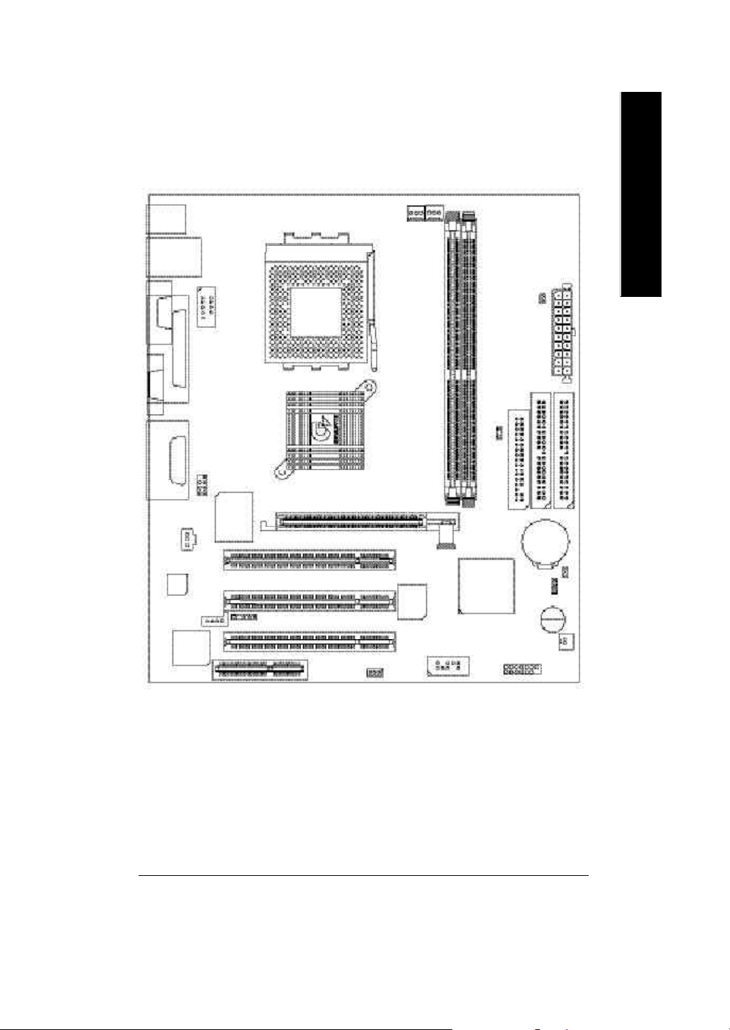
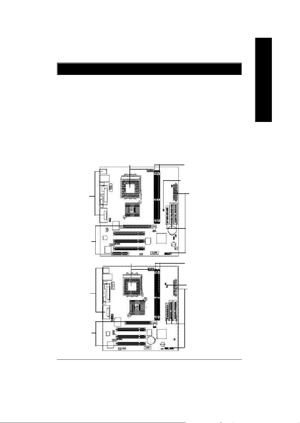
GA-7VKML (PCB Ver.: 1.1) Motherboard Layout
SYS_FAN
MS_ KB
USB
COMA
VGA
LINE_OUT
LINE_IN
MIC_IN
CODEC
CD_IN
RTL8100
LPT
GAME
SPDIF
LAN
F_AUDIO
IT8705F
COMB
SOCK ET A
KM266
IR
CNR1
WOL
PCI1
PCI2
PCI3
CPU_FAN
AG P
BI OS
USB1
GA-7VKML
DDR1
VT8233A
DDR2
LED1
FDD
CLK_SW
CLR_CMOS**
F_PANEL
English
ATX
IDE1
IDE2
BAT1
CI
BZ1
S_IRQ
"**" Supported on motherboard version: 1.1 only. Default doesn’t include the
“Shunter” to prevent from improper use this jumper. To clear CMOS, temporarily
short 1-2 pin.
Introduction- 7 -
Page 12
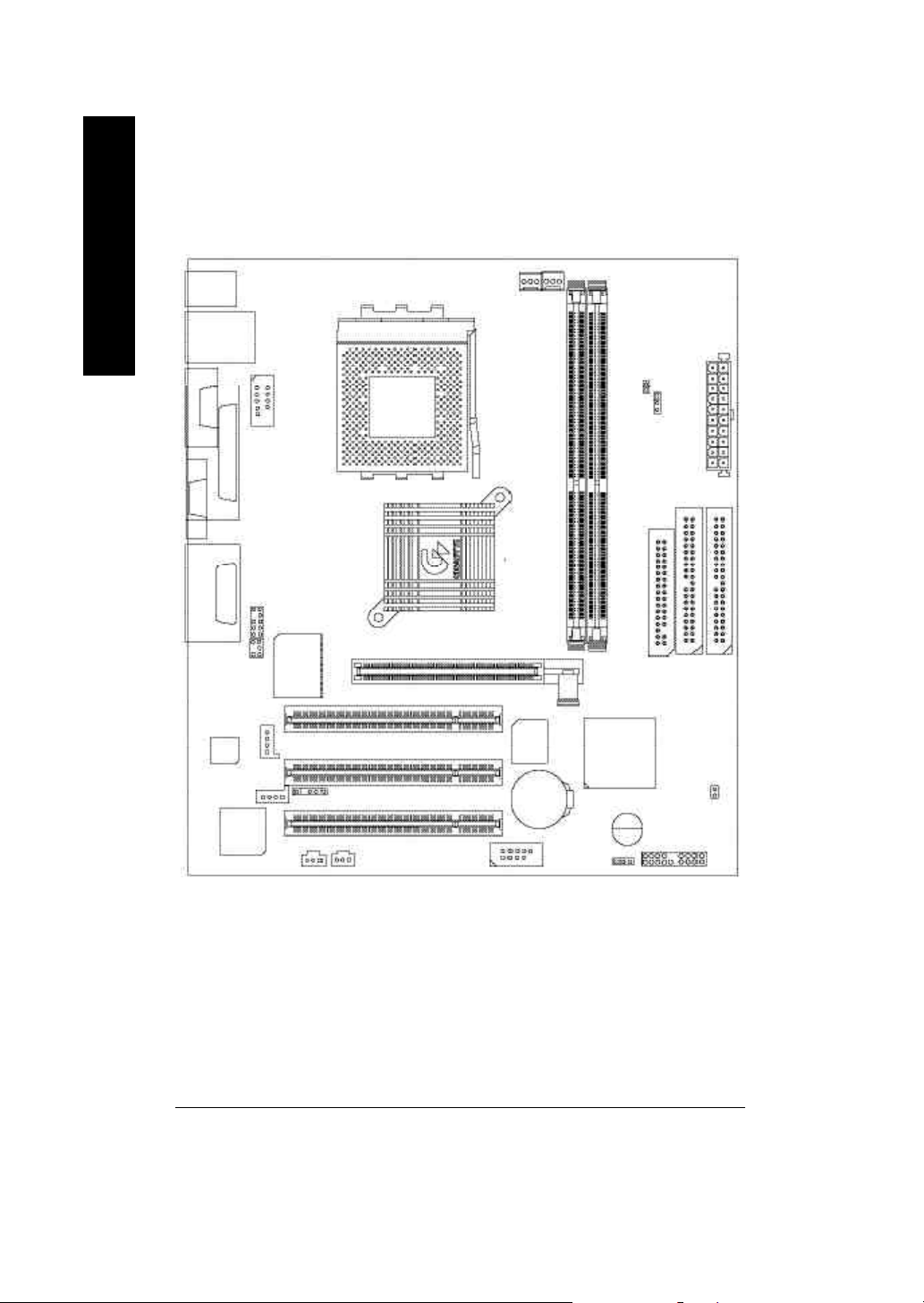
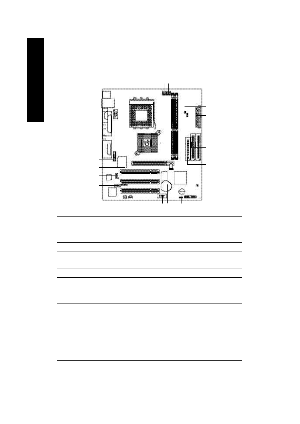
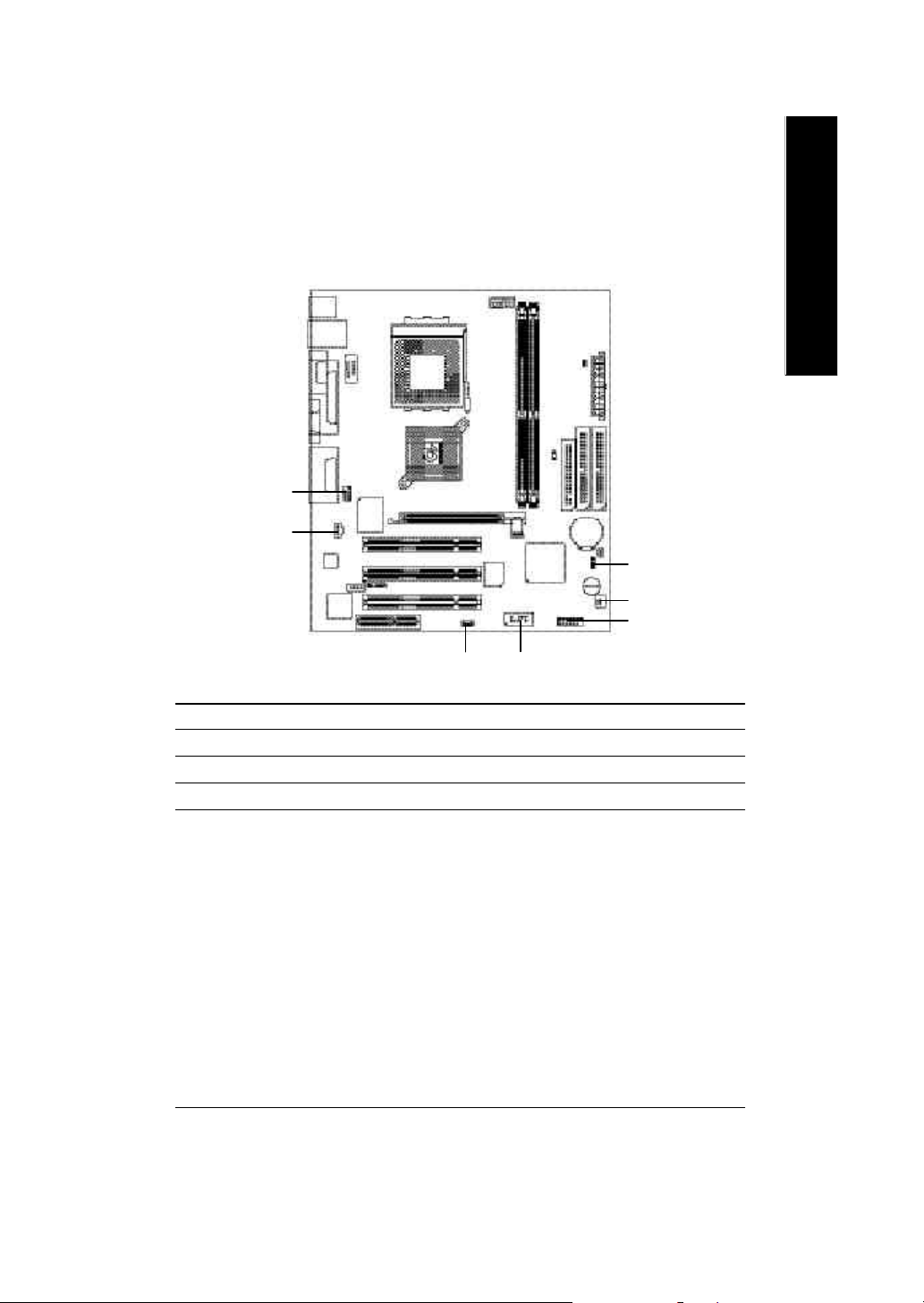
GA-7VKML (PCB 3.2/3.3/3.4) Motherboard Layout
English
MS_ KB
USB
COMA
VGALINE_OUT
LINE_IN
MIC_IN
SUR_CEN **
CODEC
- P- DL
LAN *
COMB
LPT
F_AUDIO
GAME
IT8705F
AUX_IN
CD_IN
RTL
8100 *
SPDIF ** SPDIF_IN **
CPU_FAN
SYS_FAN
RAM_LED
CLK_JP
SOCK ET A
ATX
GA-7VKML
KM266
PCI1
PCI2
IR
PCI3
USB1
DDR1
AG P
BI OS
BAT1
PWR_LED
DDR2
VT8233A
BZ1
FDD
F_PANEL
IDE1
IDE2
CI
" * " Not Supported 7VKML-DL (PCB VER:3.4)
" ** " Supported 7VKML-P / 7VKML-DL (PCB VER:3.4)
- 8 -GA-7VKML Series Motherboard
Page 13
Chapter 2 Hardware Installation Process
To set up your computer, yo u must complete the following setups:
Step 1- Set system Switch (CLK_SW)...for PCB Ver. 1.1
Step 1- Set system Jumper(CLK_JP)...for PCB Ver. 3.2
Step 2- Install the Central Processing Unit (CPU)
Step 3- Install memory modules
Step 4- Install expansion cards
Step 5- Connect ribbon cables, cabinet wires, and power supply
Step 6- Setup BIOS software
Step 7- Install supporting software tools
Step 2
Step 3
Step 1
English
Step 5
Step 4
Step 5
Step 4
Step 2
Step 5
PCB Ver. 1.1
Step 3
Step 1
Step 5
PCB Ver. 3.2
Introduction- 9 -
Page 14
Step 1: Install the Central Processing Unit (CPU)
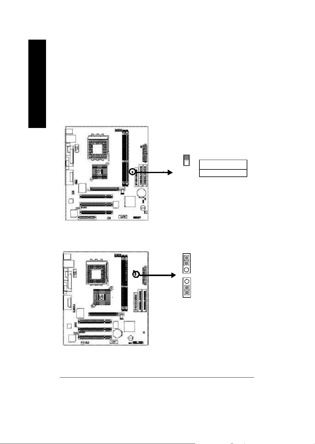
Step1-1: CPU Speed Setup
English
The sy stem bus frequency ca n be switched at 100/133MHz by adjusting CLK_SW.
(The frequency ratio depend on C PU.)
PCB Ver: 1.1 used
The sy stem bus frequency ca n be switched at 100/133MHz by adjusting CLK_JP.
(The frequency ratio depend on C PU.)
PCB Ver: 3.2 ~ 3.4 used
1
ON
CLK_SW
CLK_SW
OFF: 133MHz
ON: 100MHz
Default Setting: 100MHz
1
1-2 close: 100 MHz
1
2-3 close: 133 MHz
Default Setting: 100MHz
- 10 -GA-7VKML Series Motherboard
Page 15
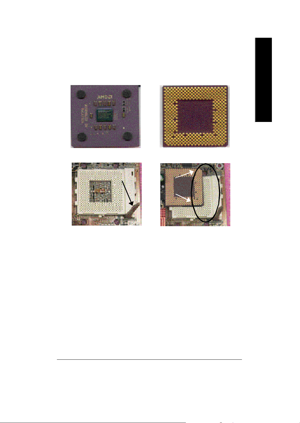
Step1-2: CPU Installation
English
CPU Top View
CPU Bottom View
Socket Actuation Lever
Pin1 indicator
1. Pull up the CPU socket lever
and up to 90-degree angle.
2. Locate Pin 1 in the socket and look
for a (golden) cut edge on the CPU
upper corner. Then insert the CPU
into the socket.
M Please make sure the CPU type is supported by the motherboard.
M I f you do not match the CPU socket Pin 1 and CPU cut edge well, it will cause
improper installation. Please change the insert orientation.
Hardware Installation Process- 11 -
Page 16
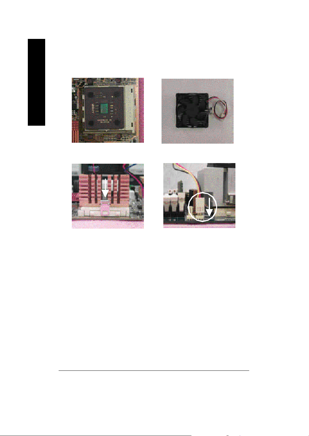
Step1-3: CPU Heat Sink Installation
English
1.Press down the CPU socket
lever and finish CPU installation.
3.Fasten the heatsink supporting-base
onto the CPU socket on the m ain-
board.
2.Use qualified fan approved by AMD.
4.Make sure the CPU fan is plugged to
the CPU fan connector, than install
complete.
M Please use AMD approved cooling fan.
M We recommend you to apply the thermal paste to provide better heat
conduction between your CPU and heatsink.
M Make sure the CPU fan power cable is plugged in to the CPU fan connector,
this completes the installation.
M Please refer to CPU heat sink user’s manual for more detail installation procedure.
- 12 -GA-7VKML Series Motherboard
Page 17

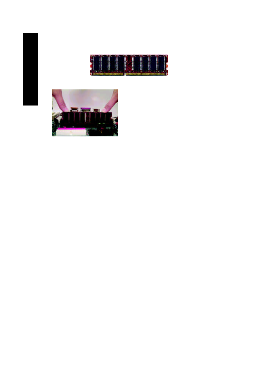
Step 2: Install memory modules
The motherboard has 2 dual inline memory module (DIMM) sockets. The BIOS wil l automati-
cally detects memory type and size. To install the memory module, ju st pu sh it v ertically into the
DIMM Slot. The DIMM module can only fit in one d irection due to th e notch. Memory siz e can v ary
between sockets.
Total Memory Sizes With Unbuffered D DR DIM M
Devices used on DIMM 1 DIMMx64/x72 2 DIMMsx64/x72
64 Mbit (2M x8x 4 banks) 128 MBytes 256 MBytes
64 Mbit (1Mx 16x4 banks) 64 MBytes 128 MBytes
128 Mbit(4Mx8x4 banks) 256 MBytes 512 MBytes
128 Mbit(2Mx16x4 banks) 128 MBytes 256 MBytes
256 Mbit(8Mx8x4 banks) 512 MBytes 1 GBytes
256 Mbit(4Mx16x4 banks) 256 MBytes 512 MBytes
512 Mbit(8Mx16x4 banks) 512 MBytes 1 GBytes
English
Hardware Installation Process- 13 -
Page 18
English
DDR Introduction
is a high performance and cost-effectiv e solution that allow s eas y ado ptio n for memory v endors,
OEMs and system integrators.
SDRAM infrastructure, yet makes awesome ad vances in solving the system performanc e bottle-
neck by doubling the memory bandwidth. DDR SDRAM will o ffer a superior solution and migration
path from existing SDRAM designs due to its availability, pricing and overall market support. PC 2100
DDR memory (DDR266) double s the data rate through reading and writing at both the risi ng a nd
falling edge of the clock, achiev ing data bandw i dth 2X greater than PC 133 when running with the
same DRAM clock frequency. With peak bandwidth of 2.1GB per second, D DR memo ry enables
system OEM s to build hi gh per formance and low latency D RAM subsystems that are suitable for
servers, w orkstations, high-end PC 's and v alue d esktop SM A sy stems. With a core voltage of only
2.5 Volts compared to conventional SDRAM's 3.3 vol ts, DDR memory i s a com pelling solution for
small form factor desktops an d notebook applications.
DDR
1. The DIMM slot has a notch, so the DIMM
memory module can only fit in one direction.
2. Insert the DIMM memory m odule verticallyinto the
DIMM slot. Then push it down.
3. Close the plastic clip at both edges of theDIM M slots
to lock the DIMM module.
Reverse the installation steps when you w is h to
remove the DIMM module.
Established on the existing SDRAM industry infrastr ucture, DDR ( Double Data Rate) memory
DDR memory is a sensible evolutionary solution for the PC industry that builds on the ex i sting
M W hen RAM_LED is ON, do not install/remove DDR from socket.
M Please note that the DIMM module can only fit in one direction due to the two
notches. Wrong orientation will cause improper installation. Please change
the insert orientation.
- 14 -GA-7VKML Series Motherboard
Page 19
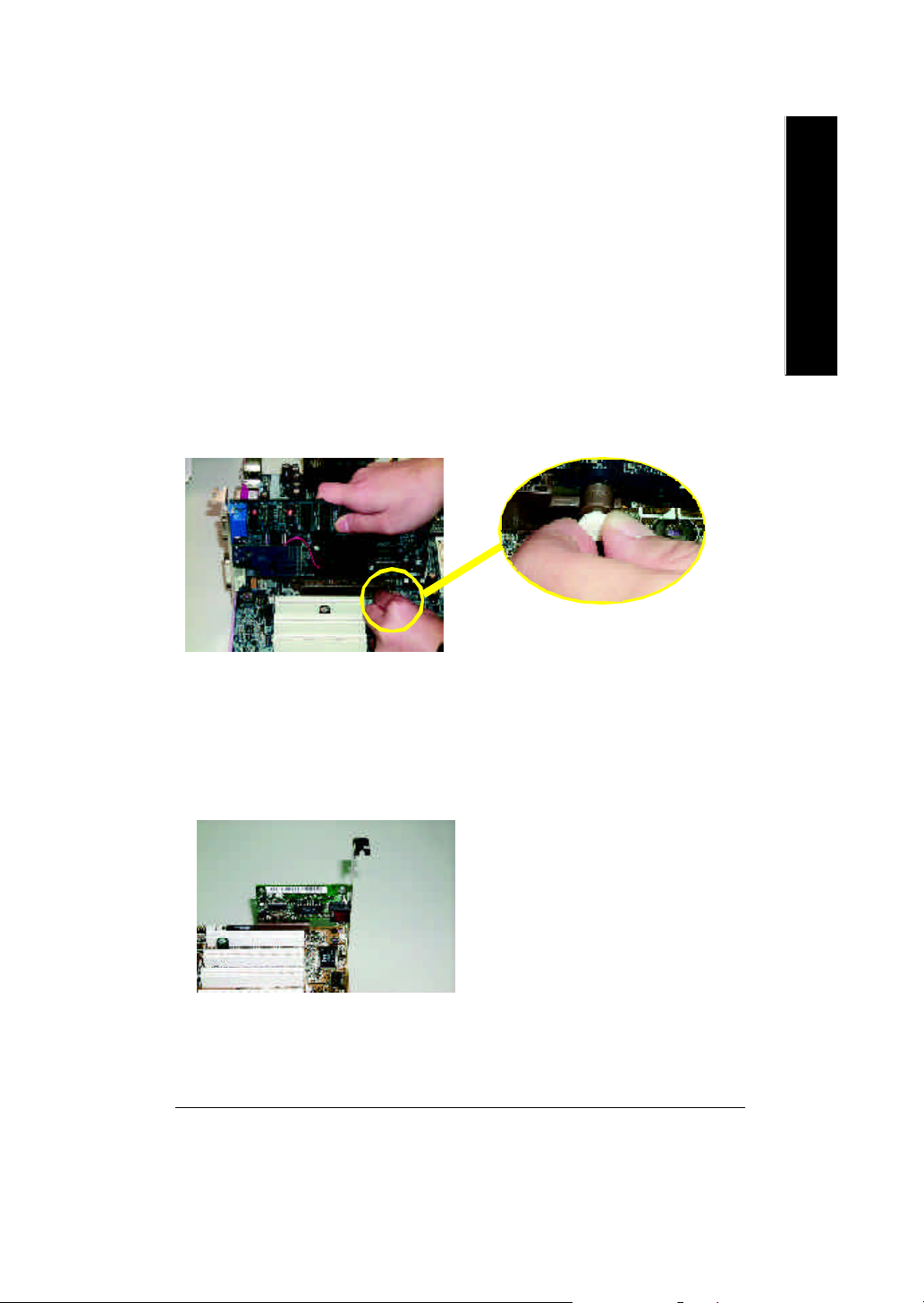
Step 3: Install expansion cards
1. Read the related expansion card’s instruction document before install the ex pansion ca rd into
the computer.
2. Remove your computer’s chassis cover, screws and slot bracket from the computer.
3. Press the expansion card firmly into expans ion slo t in mo therboard.
4. Be sure the metal contacts on the card are indeed seated in the slot.
5. Replace the screw to secure the slot bracket of the expans ion ca rd.
6. Replace your computer’s chassis cover.
7. Power on the computer, if necessary, setup BIOS utility of expansion card from BIOS.
8. Install related driver from the operating system
Please carefully pull out the small whitedraw able bar at the end of the AGP slot when
you try to install/ Un install the AGP card.
AGP Card
Please align the AGP card to the onboard AGP
slot and press firmly down on the slot .Make
sure your AGP card is locked by the small
white- drawable bar.
English
Issues To Beware Of When Installing CNR (Only for PCB Ver. : 1.1)
Please use standard CNR card like the on e in order to avoid mechanical problem.
Standard CNR card
Hardware Installation Process- 15 -
Page 20
Step 4: Connect ribbon cables, cabinet wires, and power
supply
English
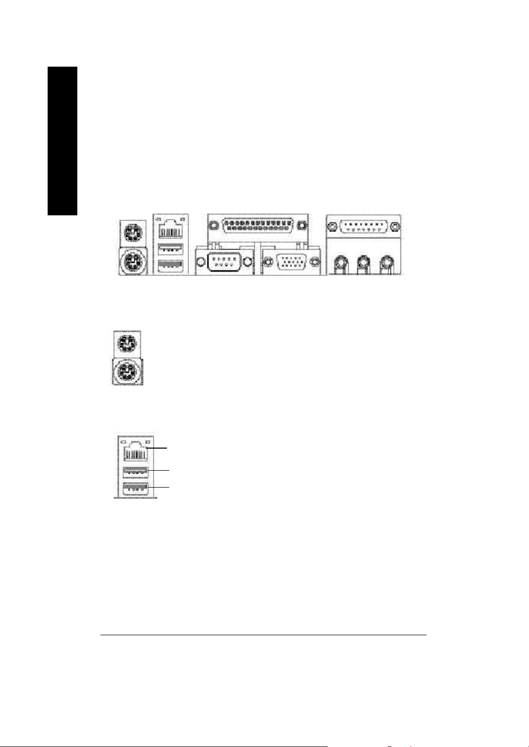
Step4-1: I/O Back Panel Introduction
v w
u
u PS/2 Keyboard and PS/2 Mouse Connector
PS/2 Mouse Connector
(6 pin Female)
PS/2 Keyboard Connector
(6 pin Female)
v USB & LAN Connector
LAN *
USB 1
USB 0
ØThis connector supports standard PS/2 keyboard
and PS/2 mouse.
Ø Before you connect your device(s) into USB
connector(s), please make sure your device(s)
such as USB keyboard,mouse, scanner, zip,
speaker..etc. Hav e a standard USB interface.
Also make sure your OS supports USB
controller. If y our OS does not support USB
controller, please contact OS vendor for possible
patch or driver upgrade. For mor e information
please contact your OS or device(s) ve ndors.
x
y
" * " Not Supported 7VKML-DL (PCB VER:3.4)
- 16 -GA-7VKML Series Motherboard
Page 21
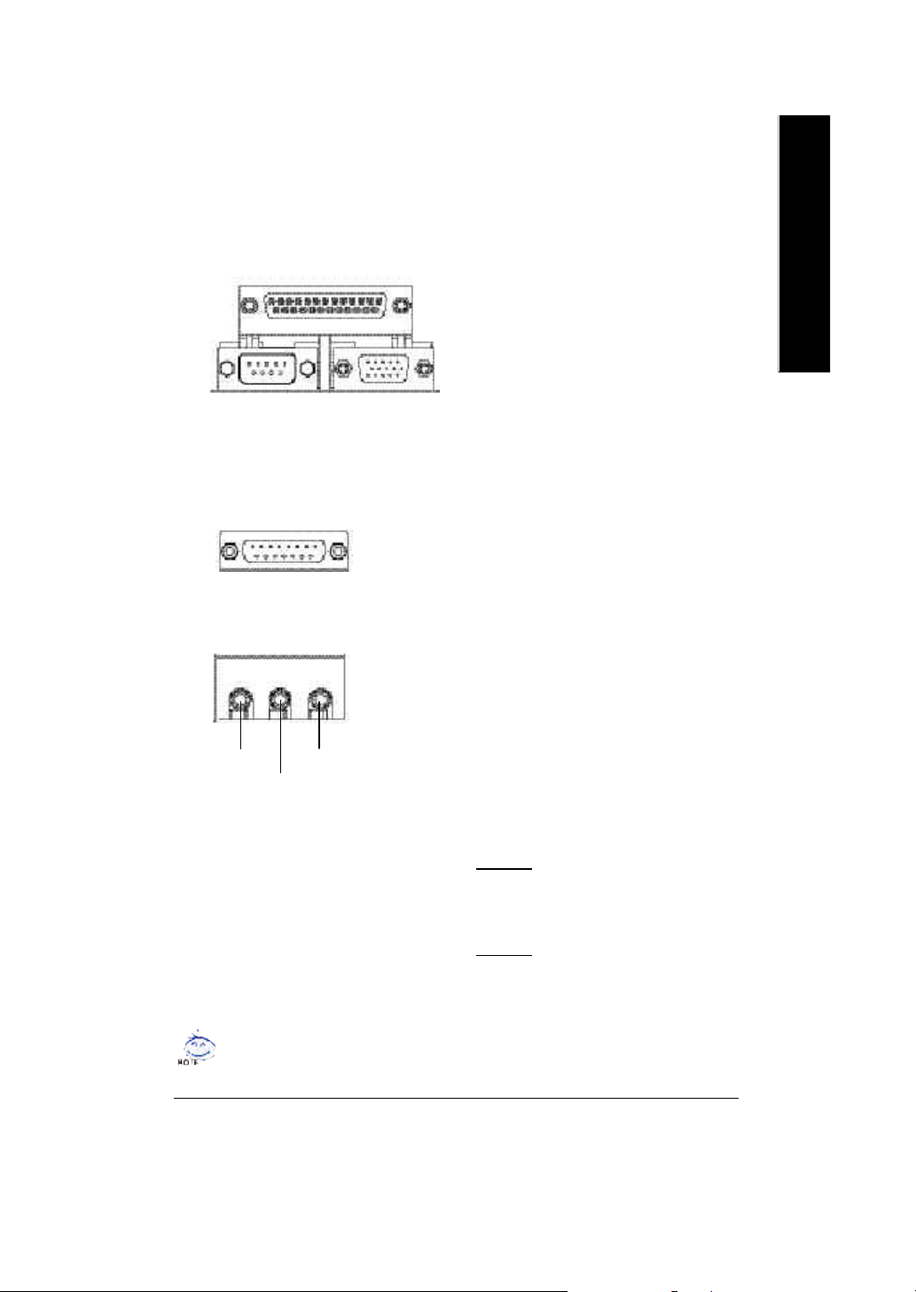
w Parallel Port and VGA Port/COMA Port
English
Parallel Port
(25 pin Female)
COMA
Serial Port
(9 pin Male)
x Game /MIDI Ports
Joystick/ MIDI (15 pin Female)
y Audio Connectors
Line Out
MIC In
Line In
ØThis mainboard sutports 1 standard COM port,
1 VGA port and 1 LPT port. Device like printer
can be connected to LPT port ; mouse and
modem etc can be connected to COM port.
VGA
VGA Port
(15 pin Female)
ØThis connector supports joystick, MIDI key
board and other relate audio devices.
Ø After install onboard audio driver, you may
connect speaker to Line Out jack, micro phone
to MIC In jack.
Device like CD-ROM , walkman etc can be
connected to Line-In jack.
Please note:
You are able to use 2-/4-/6- channel audio
feature by S/W selection.
If you want to enable 6-channel function, y ou
have 2 choose for hardware connection.
Method1:
Connect "Front Speaker" to "Line Out"
Connect "Rear Speaker" to "Line In"
Connect "Center and Subwoofer" to " MIC Out" .
Method2:
You can refer to page 24, and contact your
nearest dealer for optional SUR_CEN cable.
If you want the detail information for 2-/4-/6-channel audio setup
installation, please refer to page 79.
Hardware Installation Process- 17 -
Page 22
Step4-2: Connectors Introduction (For PCB Ver. : 3.2 ~ 3.4)
English
15
10
19
13
11
12
2
1
7
3
5
4
16
1718
1) CPU_FAN 10) F_AUDIO
2) S YS _FAN 11) AUX_IN
3) ATX 12) CD_IN
4) FDD 13) IR
5) I DE1/I DE2 14) USB1
6) PW R_LED 15) COMB
7) RAM_LED 16) CI
8) F_PANEL 17) SPDIF_IN *
9) BAT1 18) SPDIF *
19) SUR_CEN *
" * " Supported 7VKML / 7VKML-P / 7VKML-DL (PCB VER:3.4)
- 18 -GA-7VKML Series Motherboard
8
6914
Page 23
1) CPU_FAN (CPU FAN Connector)
1
GND
Sense
+12V/Control
English
Ø Plea se note, a p roper installation of the CPU
cooler is essential to prevent the CPU from run
ning und er abnormal cond ition or damaged by
overheating.The CPU fan connector supports
Max. current up to 600mA .
2) SYS_FAN (System FAN Connector)
1
GND
Sense
+12V/Control
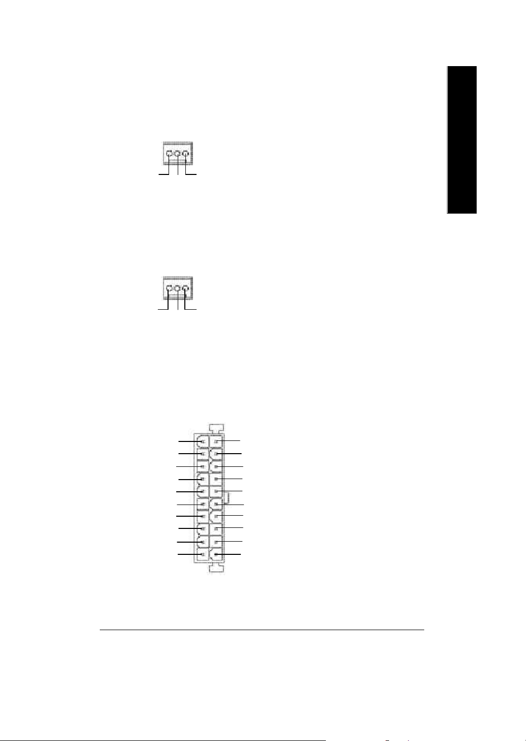
3) ATX (ATX Power)
20
+12V
5V SB (Stand by +5V)
Power Good
GND
VCC
GND
VCC
GND
3.3V
3.3V
1
Ø This connector allows you to link with
the cooling fan on the sy stem case to
lower the sy stem temp erature.
Ø AC power cord should only be connected to
your pow er supply unit after ATX pow er cable
and other related devices are firmly connected
VCC
to the mainboard.
VCC
-5V
GND
GND
GND
PS-ON(Soft On/Off)
GND
-12V
3.3V
Hardware Installation Process- 19 -
Page 24
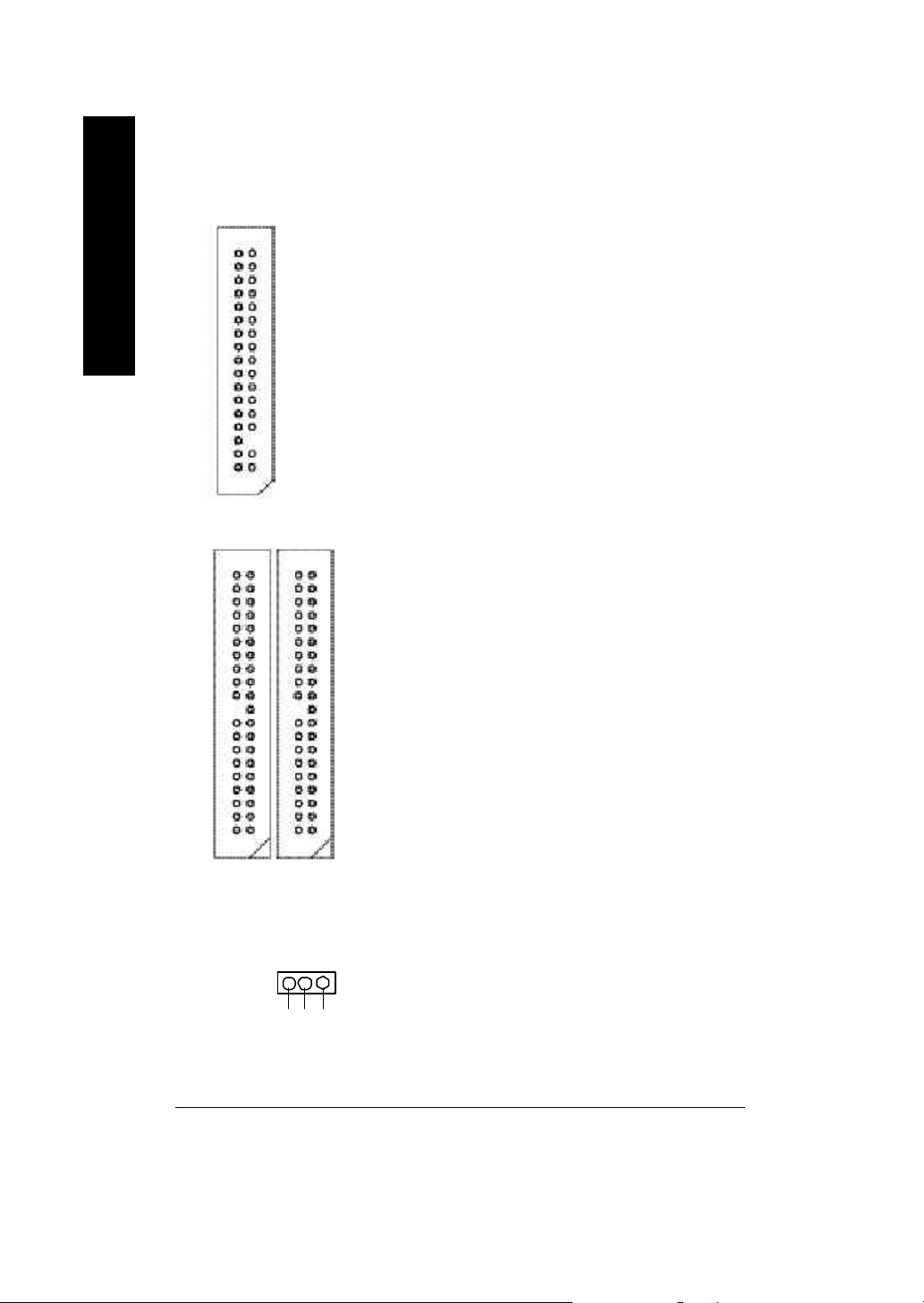
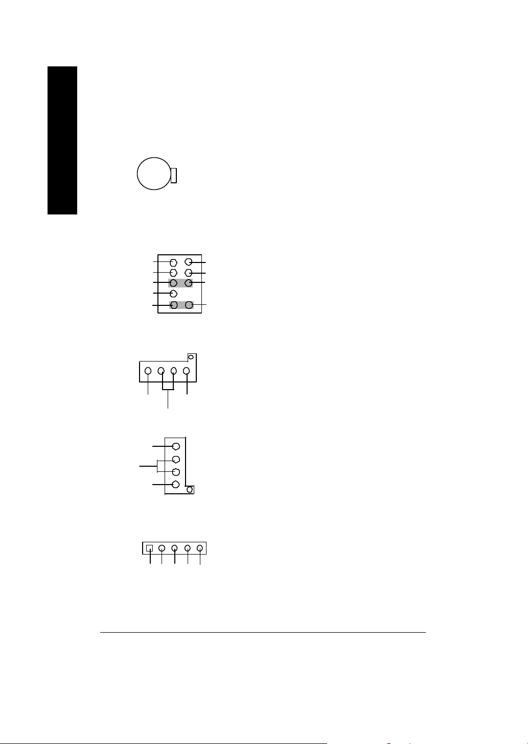
4) FDD (Floppy Connector)
English
5) IDE1/IDE2 [IDE1 (Primary), IDE2(Secondary) Connector]
Ø Please connect the floppy driver ribbon cables
to FDD. It supports 360K,1.2M,720K,1.44M
and 2.88M bytes floppy di sk types.
The rad stripe of the rib bn cable must be the
same side with the Pin1.
1
Ø Imp ortant N otice:
Please connect first harddisk to IDE1 and
connect CDROM to IDE2.
The rad stripe of the ribbn cable must be the
same side with the Pin1.
IDE1
1
6 ) PWR_LED
IDE2
1
Ø PWR_LED is connect with the system power
1
MPD+
MPD-
MPD-
indicator to indicate whether the system is
on/off. It will blink when the system enters
suspend mode. If you use dual color LED,
power LED will turn to another color.
- 20 -GA-7VKML Series Motherboard
Page 25
7) RAM_LED
+
-
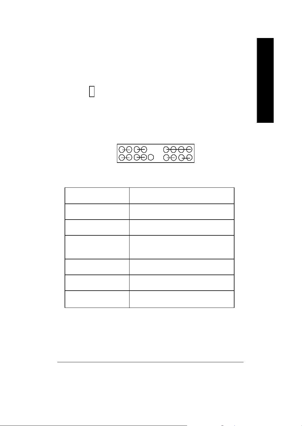
8 ) F_PANEL (2x10 pins jumper)
MPD+
MPD-
Ø Do no t remov e memory modules w hile
DIMM LED is on. It might cause short or
other unex pected damages due to the
2.5V stand by voltage. Remove memory
modules only when AC Power cord is
disconnected.
PW+
PW-
SPK+
SPK-
English
NC
1
1
GD+
GD-
1
1
2 20
1
1
HD+
GN (Green Switch) Open: Normal Operation
GD (Green LED) Pin 1: LED anode(+)
HD (IDE Hard Disk Active LED) Pin 1: LED anode(+)
SPK (Speaker Connector) Pin 1: VCC(+)
RST (Reset Sw itch) Open: Normal Operation
PW (Soft Power Connector) Open: Normal Operation
MPD(Message LED/Power/ Pin 1: LED anode(+)
Sleep LED) Pin 2: LED cathode(-)
1
HD-
RST-
RST+
Close: Entering Green Mode
Pin 2: LED cathode(-)
Pin 2: LED cathode(-)
Pin 2- Pin 3: NC
Pin 4: Data(-)
Close: Reset H ardware Sy stem
Close: Power On/Off
1
GN+
GN-
19
Ø Please conne ct the power LED, PC s peaker, reset sw itch and power switch etc of y our chassis
front panel to the F_PANEL connector according to the pin as signme nt abo ve.
Hardware Installation Process- 21 -
Page 26
9 ) BAT1 (Battery)
English
CAUTION
v Danger of ex plosion if battery is incorre ctly
replaced.
+
v Replace on ly w ith the same or equiv a lent
type recommended by the manufacturer.
v Dispose of used batteries a ccording to the
manufacturer’s instructions.
10 ) F_AUDIO (Front Audio)
1
2
MIC
REF
Front Audio (R)
Reserved
Front Audio
(L)
9
GND
POWER
Rear Audio (R)
Rear Audio (L)
10
11 ) CD_IN (CD Audio Line In)
1
CD-R
12 ) AUX_IN (AUX_IN Connector )
AUX-R
GND
AUX-L
CD-L
GND
1
ØIf y ou want to use " Front Audio" connector, y ou
must move 5-6, 9-10 Jumper. In order to utilize
the front audio header, your chassis must hav e
front audio connector. A lso pleas e ma ke sure
the pin assigment on the cable is the same as
the pin assigment on the MB header. To find out
if the chassis y ou are buying support fr ont
audio connector, please contact your dealer.
Ø C onnect C D-ROM or DVD-ROM audio out
to the connector.
Ø C onnect other device(such as PC I TV Tunner
audio out )to the connector.
13 ) IR (IR)
1
NC
VCC(+5V)
IR data input
Ø Plea se note, Be careful w ith the p olarity of
the IR connector while you connect the IR.
Please contact you nearest dealer for optional
IR device.
GND
IR data output
- 22 -GA-7VKML Series Motherboard
Page 27
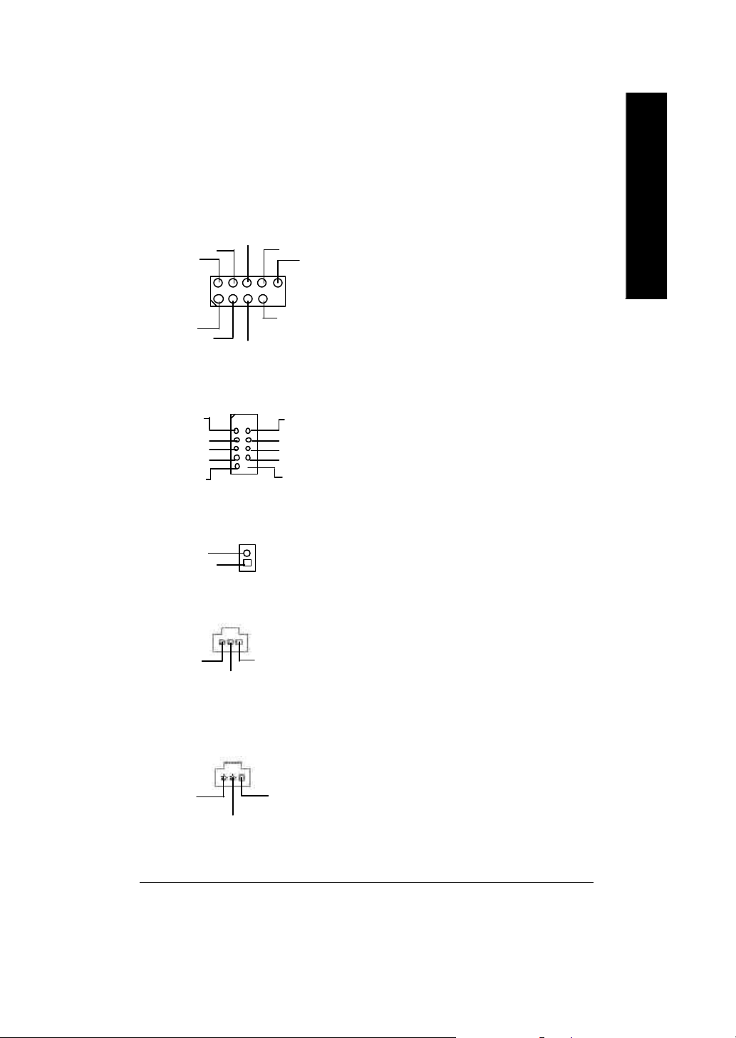
14 ) F_USB1 (Front USB Connector)
(F_USB1 connector in yellow is for
USB 1.1)
1
USB Dy+
USB Dx+
GND
USB
Over
Current
GND
USB Dy-
Power
Power
USB Dx-
Ø Be careful with the polarity of the front
USB connector. Check the pin assignment
while you connect the front USB cable.
Please contact your nearest dealer for
optional front U SB cable.
15 ) COM B ( White ) Ø Be ca reful w ith the polarity of the COMB
NDCDB-
NSOUTB
GND
NRTSB-
NRIB-
1 2
9 10
NSINB
NDTRBNDSRB-
NCTSBNC
connector. Check the pin assignment
while you connect the COM B cable.
Please contact your nearest dealer for
optional COMB cable.
English
16 ) CI (Case Open)
Signal
GND
17 ) SPDIF_IN *
GND
SPDIF IN
18 ) SPDIF *
SPDIF Out
1
1
VCC
1
VCCGND
Ø This 2 pin connector allows y our system to
enable or disable the “case open” item in
BIOS if the system case begin remove.
Ø The SPDIF output is capable of providing
digital audio to external speakers or com
pressed AC3 data to an external Dolby
Digital Decoder. Use this feature only when
your stereo system has digital input
function.
Ø U se this feature only w hen y our device has
digital output function.
" * " Supported 7VKML / 7VKML-P / 7VKML-DL (PCB VER:3.4)
Hardware Installation Process- 23 -
Page 28

19 ) SUR_CEN *
BASS_OUT
English
SUR OUTR
CENTER_OUT
GND
SUR OUTL
1
Ø Please contact your nearest dealer for optional
SUR_CEN cable.
" * " Supported 7VKML / 7VKML-P / 7VKML-DL (PCB VER:3.4)
- 24 -GA-7VKML Series Motherboard
Page 29
Step4-3: Connectors Introduction (For PCB Ver. : 1.1)
21
23
English
26
25
20
24
20) F_Panel 24) WOL
21) F_AUDIO 25) S_IRQ
22) USB1 26) CLR_CMOS
23) SPDIF
22
Hardware Installation Process- 25 -
Page 30
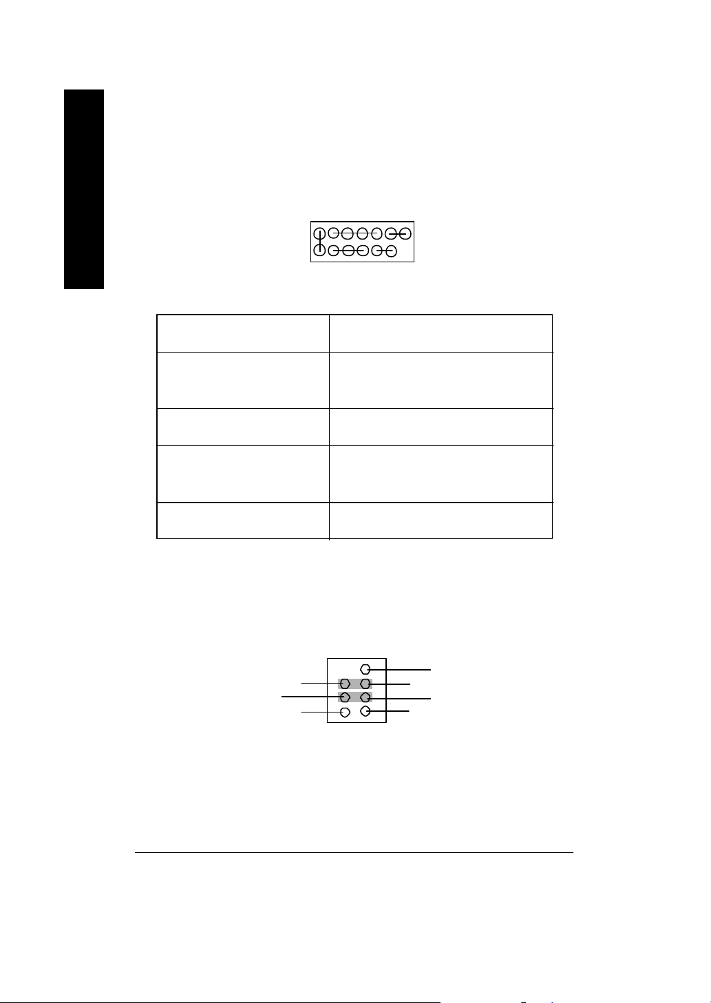
20 ) F_PANEL (2x7 pins connector)
English
HD-
SPK-
2
1
1
HD+
PD_Y-
HD (IDE Hard Disk Active LED) Pin 1: LED ano de(+)
SPK (Speaker Connector) Pin 1: VCC(+)
RST (Reset Sw itch) Open: Normal Operation
PD+/PD_G-/PD_Y-(Power LED) Pin 1 : LED anode(+)
PW (Soft Power Connector) Open: Normal Operation
SPK+
RST+
RST-
1
14
13
PD+
PW-
PD_G-
Pin 2: LED cathode(-)
Pin 2- Pin 3: NC
Pin 4: Data(-)
Close: Reset H ardware Sy stem
Pin 2: LED cathode(-)
Pin 3: LED cathode(-)
Close: Power On/Off
PW+
Ø Please connect the power LED, PC speaker, reset switch and power switch etc of y our chassis
front panel to the F_PANEL connector according to the pin as signme nt abo ve.
21 ) F_AUDIO (Front Audio)
8 7
GND
Rear Audio (L)
Rear Audio (R)
GND
2
1
Ø If you want to use " Front Audio" connector, you must remove 3-4, 5 -6 Jumper. In order to utilize
the front audio header, your chassis mus t have front audio connector. Al so pl ease m ake s ure
the pin assigment on the cable is the same as the pin assigment on the M B he ader. To find out
if the chassis you are b uying support fro nt audio connector, p lease contact your dealer.
- 26 -GA-7VKML Series Motherboard
Front Audio (L)
Front Audio (R)
MIC
Page 31

22 ) USB1 (Front USB)
NC
GND
1
Power
USB D2-
USB D3+
USB D3-
NC
USB D2+
English
Ø Be careful with the polarity of the front panel
USB connector. Check the pin assignment
while you connect the front panel U SB cable.
Please contact your nearest dealer for
optional front panel USB cable.
Power
GND
23 ) SPDIF (SPDIF)
GND
SPDIF OUT
1
VCC
24 ) WOL (Wake On Lan)
1
+5V SB
GND
Signal
25 ) S_IRQ (Serial IRQ)
GND
Signal
Ø The SPDIF output is capable of providing
digital audio to external speakers or
compressed AC3 data to an external Dolby
Digital Decoder. Use this feature only when
your stereo system has digital output function.
Ø This connector allows the remove
servers to manage the system that in
stalled this mainboard via your network
adapter which also supports WOL.
Ø Please N ote: For special design, for
example: PCMCIA add on card.
1
Hardware Installation Process- 27 -
Page 32

26 ) CLR_CMOS (Clear CMOS Function)
English
Ø Please note: You may clear the CMOS data to its defau lt v alues by this jumper.
Default doesn’t include the “Shunter” to prevent from improper use this jumper.
To clear CMOS, temporarily short 1-2 pin.
1-2 close: Clear CMOS
1 1
2-3 close: Normal (Default)
- 28 -GA-7VKML Series Motherboard
Page 33

English
Hardware Installation Process- 29 -
Page 34

English
- 30 -GA-7VKML Series Motherboard
Page 35

Chapter 3 BIOS Setup
BIOS Setup is an overview of the BIOS Setup Program. The program that allows users to modify the
basic system configuration. This type of information is stored in battery -b acked C M OS RAM so that it
retains the Setup information when the power is turned off.
English
ENTERING
Powering ON the computer and pressing <Del> immediately will allow y ou to enter Setup. If you require
more advanced BIOS settings, please go to “Adv anced BIOS” setting menu.To enter Advanced BIOS
setting menu, press “Ctrl+F1” key on the BIOS screen.
CONTROL
<á> Mov e to previous item
<â> Mov e to next item
<ß> Move to the item in the left hand
<à> Move to the item in the right hand
<Enter> Select item
<Esc> M ain M enu - Quit and not sav e changes into CM OS Status Page Setup Menu and
<+/PgUp> Increase the numeric value or make changes
<-/PgDn> Decrease the numeric value or make changes
<F1> General help, only for Status Page Setup Menu and Option Page Setup Menu
<F2> Reserved
<F3> Reserved
<F4> Reserved
<F5> Restore the previous C M OS value from CMOS, only for Option Page Setup Menu
<F6> Load the file-safe default CMOS value from BIOS default table
<F7> Load the Optimized Defaults
<F8> Q-Flash utility
<F9> System Information
<F10> Save all the CMOS changes, only for Main Menu
SETUP
K EYS
Option Page Setup Menu - Exit current page and return to M ain M enu
- 31 - BIOS Setup
Page 36

G ETTING HELP
The on-line description of the highlighted setup function is display ed at the bottom of the screen.
English
Press F1 to pop up a small help window that descr ibes the appropriate keys to use and the possible
selections for the highlighted item. To exit the H elp Window press <Esc>.
The Main Menu (For example: BIOS Ver. : F9a)
Once you enter AMI BIOS CMOS Setup Utility, the M ain M enu (Figure 1) w ill appear on the screen.
The Main Menu allows you to select from eight setup functions and two exit choices. Use arrow key s to
select among the items and press <Enter> to accept or enter the sub-menu.
STANDARD CMOS SETUP INTEGRATED PERIPHERALS
BIOS FEATURES SETUP HARDWARE MONITOR & MISC SETUP
CHIPSET FEATURES SETUP SUPERVISOR PASSWORD
POWER MANAGEMENT SETUP USER PASSWORD
PNP / PCI CONFIGURATION IDE HDD AUTO DETECTION
LOAD FAIL-SAFE DEFAULTS SAVE & EXIT SETUP
LOAD OPTIMIZED DEFAULTS EXIT WITHOUT SAVING
ESC: Quit hifg: Select Item F5: Old Values F6: Fail-Safe Values
F7: Optimized Values F8: Q-Flash Utility F10:Save & Exit
M ain Menu
Status Page Setup Menu / Option Page Setup Menu
AMIBIOS SIMPLE SETUP UTILITY - VERSION 2.00
(C) 2001 American Megatrends, Inc. All Rights Reserved
Time, Date , Hard Disk Type…
Figure 1: Main Menu
l Standard CMOS Features
This setup page includes all the items in standard compatible BIOS.
l BIOS Features Setup
This setup page includes all the adjustable items of AMI special enhanced features.
l Chipset Features Setup
This setup page includes all the adjustable items of chipset special features.
- 32 -GA-7VKML Series Motherboard
Page 37

l Power Management Setup
This setup page includes all the adjustable items of Green function features.
l PNP/PCI Configurations
This setup page includes all the adjustable configurations of PCI & PnP ISA resources.
l Load Fail-Safe Defaults
Load Fail-Safe Defaults option loads preset system parameter values to set the system in its
most stable configurations.
l Load Optimized Defaults
Load Optimized Defaults option loads preset system parameter values to set the system in its
highest performance configurations.
l Integrated Peripherals
This setup page includes all onboard peripherals.
l Hardware Monitor & M ISC Setup
This setup page is auto detect fan and temperature status.
l Set Supervisor Passw ord
Set Change or disable password. It allows you to limit access to the sy stem and/or BIOS
setup.
l Set User Password
Set Change or disable password. It allows you to limit access to the sy stem.
l IDE HDD Auto Detection
Automatically configure hard disk parameters.
l Save & Exit Setup
Save CMOS value settings to CMOS and exit setup.
l Exit Without Saving
Abandon all CMOS value changes and exit setup.
English
- 33 - BIOS Setup
Page 38

Standard CMOS Features
English
System Date : Jan 08 2002 Tue
System Time : 14:44:35
TYPE SIZE CYLS HEAD PRECOMP LANDZ SECTOR MODE
Pri Master : Auto
Pri Slave : Auto
Sec Master : Auto
Sec Slave : Auto
AMIBIOS SETUP - STANDARD CMOS SETUP
( C ) 2001 American Megatrends, Inc. All Rights Reserved
Floppy Drive A : 1.44 MB 3
Floppy Drive B : Not Installed Other Memory : 384 Kb
Virus Protection : Disabled Total Memory : 96 Mb
Date is standard format ESC : Exit
Month : Jan - Dec hi : Select Item
Day : 01- 31 PU / PD / + / - :Modify
Year : 1990 - 2099 (Shift) F2 : Color
1/2
Figure 2: Standard CMOS Setup
Base Memory : 640 Kb
Extended Memory : 95 Mb
F System Date
The date format is <week>, <month>, <day>, <year>.
8Week The week, from Sun to Sat, determined by the BIOS and is display only
8Month The month, Jan. Through Dec.
8Day The day, from 1 to 31 (or the maximum allowed in the month)
8Year The year, from 1990 through 2099
- 34 -GA-7VKML Series Motherboard
Page 39

F System Time
The times format in <hour> <minute> <second>. The time is calculated base on the 24-hour
military time clock. For example, 1 p.m. is 13:00:00.
F Primary Master, Slave / Secondary M aster, Slave
The category identifies the ty pes of hard disk from driv e C to F that has been installed in the
computer. There are two types: auto type, and manual type. M anual type is user-definable; Auto
type which will automatically detect H DD type.
Note that the specifications of your driv e must match w ith the driv e table. The hard disk will not
work properly if you enter improper information for this category .
If you select User Type, related information will be asked to enter to the following items. Enter the
information directly from the key board and press <Enter>. Such information should be provided in
the documentation form your hard disk vendor or the system manufacturer.
8SIZE HDD Size
8CYLS. Number of cylinders
8HEADS number of heads
8PRECOMP write precomp
8LANDZONE Landing zone
8SECTORS number of sectors
8MODE Logical block addressing
If a hard disk has not been installed select NONE and press <Enter>.
English
F Floppy Drive A / Drive B
The category identifies the ty pes of floppy disk driv e A or driv e B that has been installed in the
computer.
8Not Installed No floppy drive installed
81.2M, 5.25 in. 5.25 inch AT-type high-density drive; 1.2M byte capacity
(3.5 inch when 3 Mode is Enabled).
8720K, 3.5 in. 3.5 inch double-sided drive; 720K byte capacity
81.44M, 3.5 in. 3.5 inch double-sided drive; 1.44M byte capacity.
82.88M, 3.5 in. 3.5 inch double-sided drive; 2.88M byte capacity.
- 35 - BIOS Setup
Page 40

F Virus Protection
English
FM emory
If it is set to enable, the category w ill flash on the screen w hen there is any attempt to write to the
boot sector or partition table of the hard disk drive. The system will halt and the following error
message will appear in the mean time. You can run anti-virus program to locate the problem.
8Enabled Activate automatically when the system boots up causing a w arning
message toappear when anything attempts to access the boot sector or hard
disk partition table
8Disabled No warning message to appear when anything attempts to access the boot
sector or hard disk partition table (Default Value)
The category is display-only which is determined by POST (Power On Self Test) of the BIOS.
Base Memory
The POST of the BIOS will determine the amount of base (or conv entional) memory installed in the
system.
The value of the base memory is typically 512 K for systems with 512 K memory installed on the
motherboard, or 640 K for systems with 640 K or more memory installed on the motherboard.
Other M emory
This refers to the memory located in the 640 K to 1024 K address space. This is memory that can be
used for different applications.
DOS uses this area to load device drivers to keep as much base memory free for application
programs. Most use for this area is Shadow RAM.
Extended Memory
The BIOS determines how much extended memory is present during the POST.
This is the amount of memory located above 1 MB in the CPU’s memory address map.
- 36 -GA-7VKML Series Motherboard
Page 41

BIOS Features Setup
AMIBIOS SETUP - BIOS FEATURES SETUP
( C ) 2001 American Megatrends, Inc. All Rights Reserved
BIOS Flash Protection : Auto
1st Boot Device : Floppy
2nd Boot Device : IDE-0
3rd Boot Device : CDROM
Floppy Drive Seek : Disabled
BootUp Num-Lock : On
Password Check : Setup ESC: Quit hifg: Select Item
S.M.A.R.T. for Hard Disks : Disabled F1 : Help PU/PD+/-/ : Modify
Interrupt Mode : APIC F5 : Old Values (Shift)F2: Color
F6 : Fail-Safe F7:Optimized
F8 : Q-Flash Utility
Figure 3: BIOS Feature Setup
FBIOS Flash Protection
This field lets you determine the states that flash BIOS.
8Auto BIOS enables flash write access automatically w hen updating BIOS data/
DMI/ESCD. (Default Value)
8Enabled During POST, DMI/ESCD w ould not be updated. But flash tools can update
BIOS always.
English
F1st / 2 nd / 3rd Boot d evice
8Floppy Select your boot device priority by Floppy.
8CDROM Select your boot device priority by CDROM.
8Disabled Disable this function.
8IDE-0~3 Select your boot device priority by IDE-0~3.
8Realtek Boot Select your boot device priority by Realtek Lan function.
- 37 - BIOS Setup
Page 42

FFloppy Drive Seek
English
FBoot Up Num-Lock
FPassword Check
FS.M .A.R.T. for Hard Disks
During POST, BIOS will determine the floppy disk driv e installed is 40 or 80 tracks. 360 K type is 40
tracks 720 K, 1.2 M and 1.44 M are all 80 tracks.
8Enabled BIOS searches for floppy disk drive to determine it is 40 or 80 tracks. Note
that BIOS can not tell from 720 K, 1.2 M or 1.44 M drive type as they are all
80tracks.
8Disabled BIOS will not search for the type of floppy disk driv e by track number. Note
that there will not be any warning message if the driv e installed is 360 K.
(Default value)
8On Keypad is number keys. (Default value)
8Off Keypad is arrow keys.
Please refer to the detail on P.55
8Always The user must enter correct password in order to access the system and/or
BIOS Setup.
8Setup The user must enter correct password in order to access BIOS setup utility.
(Default Value)
8Enabled Enable HDD S.M.A.R.T. Capability.
8Disabled Disable HDD S.M.A.R.T. Capability. (Default value)
FInterrupt Mode
8APIC Through IOAPIC generate more IRQ for sy stem use.(Default v alue)
8PIC Use AT stantard IRQ controlles to generate IRQ.
When you already have IOAPIC enable system and want to upgrade the system please note, since
running an IOAPIC enabled OS (like Windows NT,Windows 2000, Windows XP...) sy stem w ith none
IOAPIC HW support will cause the system to hang. Following are some situations users might run into:
1.An IOAPIC enabled OS and change the BIOS setting from IOAPIC to PIC, this will cause y our
system to hang.
- 38 -GA-7VKML Series Motherboard
Page 43

Chipset Features Setup
We would not suggest you change the chipset default setting unless y ou really need it.
AMIBIOS SETUP - CHIPSET FEATURES SETUP
( C ) 2001 American Megatrends, Inc. All Rights Reserved
Configure SDRAM by SPD :Enabled
SDRAM Frequency :Auto
SDRAM CAS# Latency :2.5
SDRAM Command Rate :2T Command
AGP Mode :4X
AGP Comp. Driving :Auto
Manual AGP Comp. Driving :DA
AGP Fast Write :Disabled
AGP Aperture Size :64MB
AGP Read Synchronization :Disabled
PCI Delay Transaction :Disabled
USB Controller :4 USB Ports ESC: Quit hifg: Select Item
USB Legacy Support :Disabled F1 : Help PU/PD+/-/ : Modify
USB Port 64/60 Emulation :Disabled F5 : Old Values (Shift)F2: Color
F6 : Fail-Safe F7:Optimized
F8 : Q-Flash Utility
Figure 4: Chipset Features Setup
English
#These two items will be available when "Configure SDRAM by SPD" is set to Disabled.
F Configure SDRAM by SPD
8Disabled Disable Configure SDRAM by SPD.
8Enabled Enable Configure SDRAM by SPD. (Default Value)
FSDRAM Frequency
8200MHz Set SDRAM Frequency to 200MHz.
8266MHz Set SDRAM Frequency to 266MHz.
8Auto Set SDRAM Frequency to Auto. (Default Value)
F SDRAM CAS# Latency
82 For Fastest SDRAM DIMM module.
82.5 For Slow er SDRAM DIMM module. (Default Value)
- 39 - BIOS Setup
Page 44

FSD RAM Command Rate
English
FAG P Mode
FAG P Comp. Driving
F AGP Fast Write
FAG P Aperture Size
82T Command Set SDRAM Command Rate to 2T Command. (Default Value)
81T Command Set SDRAM Command Rate to 1T Command.
84X Set AGP Mode to 4X. (Default Value)
81X Set AGP Mode to 1X.
82X Set AGP Mode to 2X.
8Auto Set AGP Comp. Driving to Auto. (Default Value)
8Manual Set AGP Comp. Driving to Manual.
If AGP Comp. Driving is Manual.
Manual AGP Comp. Driving : 00~FF
8Disabled Disable AGP Fast Write. (Default Value)
8Enabled Enable AGP Fast Write.
84MB Set AGP Aperture Size to 4MB.
88MB Set AGP Aperture Size to 8 MB.
816MB Set AGP Aperture Size to 16 MB.
832MB Set AGP Aperture Size to 32 MB.
864MB Set AGP Aperture Size to 64 MB. (Default Value)
8128MB Set AGP Aperture Size to 128 MB.
8256MB Set AGP Aperture Size to 256 MB.
F AGP Read Synchronization
8Enabled Enable AGP Read Synchronization.
8Disabled Disable AGP Read Synchronization. (Default Value)
- 40 -GA-7VKML Series Motherboard
Page 45

F PCI Delay Transaction
8Enabled Enable PCI Delay Transaction.
8Disabled Disable PCI Delay Transaction.(Default Value)
F U SB Controller
8Disabled Disable USB Controller function.
82USB Ports Enable 2USB Ports.
84USB Ports Enable 4USB Ports.
F U SB Legacy Support
8No Mice Set USB Legacy Support Keyboard / Floppy.
8All Device Set USB Legacy Support Keyboard / Mouse /Floppy.
8Disabled Disable USB Legacy Support Function. (Default Value)
F Port 64/60 Emulation
8Enabled To use USB mouse under Win NT environment, set USB Legacy
Support to KB/Mouse/FDD and USB Port 64/60 Emulation to enabled.
8Disabled Disable this Function. (Default Value)
English
- 41 - BIOS Setup
Page 46

Power Management Setup
English
ACPI Standby State :S1/POS Resume On RTC Alarm :Disabled
Power LED in S1 state :Blinking RTC Alarm Date :15
USB Dev Wakeup From S3-S5 :Disabled RTC Alarm Hour :12
Suspend Time Out(Minute) :Disabled RTC Alarm Minute :30
IRQ3 :Monitor RTC Alarm Second :30
IRQ 4 :Monitor
IRQ 5 :Ignore
IRQ 7 :Monitor
IRQ 9 :Ignore
IRQ 10 :Ignore
IRQ 11 :Ignore
IRQ 13 :Ignore
IRQ 14 :Monitor
IRQ 15 :Ignore
Soft-off by Pow er Button :Instant off
AC Back Function :Soft-Off ESC: Quit hifg: Select Item
Modem Ring / Wake On Lan :Enabled F1 : Help PU/PD+/-/ : Modify
PME Event Wake Up :Enabled F5 : Old Values (Shift)F2: Color
Keyboard Wakeup From :S1(Suspend) F6 : Fail-Safe F7:Optimized
PS/2 Mouse Wakeup From :S1(Suspend) F8 : Q-Flash Utility
AMIBIOS SETUP - POWER MANAGEMENT SETUP
( C ) 2001 American Megatrends, Inc. All Rights Reserved
Figure 5: Power Management Setup
F ACPI Standby State
8S1/POS Set AC PI standby state is S1. (Default Value)
8S3/STR Set ACPI standby state is S3.
C Power LED in S1 state
8Blinking In standby mode(S1), pow er LED w ill blink. (Default Value)
8Dual/Off In standby mode(S1):
a. If use single color LED, power LED will turn off.
b. If use dual color LED, power LED will turn to another color.
- 42 -GA-7VKML Series Motherboard
Page 47

F U SB Dev Wakeup From S3~S5
USB Dev Wakeup From S3~S5 can be set when ACPI standby state set to S3/STR.
8Enabled Enable USB Dev Wakeup From S3~S5.
8Disabled Disable U SB Dev Wakeup From S3~S5. (Default Value).
F Suspend Time Out (Minute.)
8Disabled Disabled Suspend Time Out Function. (Default Value)
81 Enabled Suspend Time Out after 1min.
82 Enabled Suspend Time Out after 2min.
84 Enabled Suspend Time Out after 4min.
88 Enabled Suspend Time Out after 8min.
810 Enabled Suspend Time Out after 10min.
820 Enabled Suspend Time Out after 20min.
830 Enabled Suspend Time Out after 30min.
840 Enabled Suspend Time Out after 40min.
850 Enabled Suspend Time Out after 50min.
860 Enabled Suspend Time Out after 60min.
F IRQ 3 ~IRQ15
8Ignore Ignore IRQ3 ~IRQ15.
8Monitor Monitor IRQ3~IRQ15.
English
F Soft-off by Power Button
8Instant-off Soft switch ON/OFF for POWER ON/OFF. (Default Value)
8Suspend Soft switch ON/OFF for suspend.
F AC Back Function
8Soft-Off When AC-power back to the system, the sy stem will be in " Soft-Off" state.
(Default Value)
8Full-On When AC-pow er back to the system, the system will be in "Full-On" state.
8Memory When AC-pow er back to the sy stem, the sy stem will return to the Last state
before AC-power off.
- 43 - BIOS Setup
Page 48

F M odem Ring /Wake On LAN
English
F PM E Event Wake U p
F K eyboard Wakeup From
F PS/2 Wakeup From
8Disabled Disabled Resume M odem Ring / Wake On LAN .
8Enabled Enabled Resume Modem Ring / Wake On LAN. (Default Value)
8Disabled Disable PM E Ev ent Wake Up.
8Enabled Enabled PME Ev ent Wake Up. (Default Value)
8S1(Suspend) Keyboard is able to Wakeup the system from S1(Suspend) state.
(Default value)
8S1/S3 Keyboard is able to Wakeup the sy stem from S1/S3 state.
8S1/S3/S4/S5 Keyboard is able to Wakeup the system from S1/S3/S4/S5 state.
8S1(Suspend) PS/2 Mouse is able to Wakeup the system from S1(Suspend) state.
(Default value)
8S1/S3 PS/2 Mouse is able to Wakeup the sy stem from S1/S3 state.
8S1/S3/S4/S5 PS/2 Mouse is able to Wakeup the system from S1/S3/S4/S5 state.
F Resume On RTC Alarm
You can set "RTC Alarm Power On" item to enabled and key in Data/time to power on
system.
8Disabled Disable this function. (Default Value)
8Enabled Enable alarm function to POWER ON system.
If RTC Alarm Lead To Power On is Enabled.
RTC Alarm Date:Everyday, 1~31
RTC Alarm Hour:0~23
RTC Alarm Minute : 0~59
RTC Alarm Second:0~59
- 44 -GA-7VKML Series Motherboard
Page 49

PNP/PCI Configuration
AMIBIOS SETUP - PNP/PCI CONFIGURATION
( C ) 2001 American Megatrends, Inc. All Rights Reserved
OnChip VGA Frame Buffer : 32MB
VGA Boot From : AGP
PCI Slot 1 IRQ Priority : Auto
PCI Slot 2 IRQ Priority : Auto
PCI Slot 3 IRQ Priority : Auto
Realtek LAN ROM initial : Yes
ESC: Quit hifg: Select Item
F1 : Help PU/PD/+/- : Modify
F5 : Old Values (Shift)F2: Color
F6 : Fail-Safe F7 : Optimized
F8 : Q-Flash Utility
Figure 6: PNP/PCI Configuration
F OnChip VGA Frame Buffer
88MB Set OnChip VGA Frame Buffer to 8MB.
816MB Set OnChip VGA Frame Buffer to 16MB.
832MB Set OnChip VGA Frame Buffer to 32MB.(Default Value)
8None Disable this function.
English
F VGA Boot From
8AGP Set VGA Boot from AGP VGA Card. (Default Value)
8PCI Set VGA Boot from PCI VGA Card.
- 45 - BIOS Setup
Page 50

F PCI Slot1, 2, 3 IRQ Priority
English
FRealtek LAN ROM initial
8Auto The system w ill reserved a free IRQ for PCI slot 1, 2, 3 device. (Default Value)
83 The system will reserved IRQ3 for PCI slot 1, 2, 3 device if no legacy
ISA device using IRQ3.
84 The system will reserved IRQ4 for PCI slot 1, 2, 3 device if no legacy
ISA device using IRQ4.
85 The system will reserved IRQ5 for PCI slot 1, 2, 3 device if no legacy
ISA device using IRQ5.
87 The system will reserved IRQ7 for PCI slot 1, 2, 3 dev ice if no legacy ISA
device using IRQ7.
89 The system will reserved IRQ9 for PCI slot 1, 2, 3 dev ice if no legacy ISA
device using IRQ9.
810 The system will reserved IRQ10 for PCI slot 1, 2, 3 dev ice if no legacy
ISA device using IRQ10.
811 The system will reserv ed IRQ11 for PCI slot 1, 2, 3 device if no legacy
ISA device using IRQ11.
8Yes Enabled Realtek LAN ROM initial. (Default Value)
8No Disabled Realtek LAN ROM initial.
- 46 -GA-7VKML Series Motherboard
Page 51

Load Fail-Safe Defaults
AMIBIOS SIMPLE SETUP UTILITY - VERSION 2.00
(C) 2001 American Megatrends, Inc. All Rights Reserved
STANDARD CMOS SETUP INTEGRATED PERIPHERALS
BIOS FEATURES SETUP HARDWARE MONITOR & MISC SETUP
CHIPSET FEATURES SETUP SUPERVISOR PASSWORD
POWER MANAGEMENT SETUP USER PASSWORD
PNP / PCI CONFIGURATION IDE HDD AUTO DETECTION
LOAD FAIL-SAFE DEFAULTS SAVE & EXIT SETUP
LOAD OPTIMIZED DEFAULTS EXIT WITHOUT SAVING
ESC: Quit hifg: Select Item F5: Old Values F6: Fail-Safe Values
F7: Optimized Values F8: Q-Flash Utility F10:Save & Exit
FLoad Fail-Safe Defaults
Fail-Safe defaults contain the most appropriate system parameter v alues of to configure
the system to achieve maximum stability.
Load Fail-Safe Defaults? (Y/N)?N
Load Fail-Safe Defaults
Figure 7: Load Fail-Safe Defaults
English
- 47 - BIOS Setup
Page 52

Load Optimized Defaults
English
FLoad Optimized Defaults
AMIBIOS SIMPLE SETUP UTILITY - VERSION 2.00
(C) 2001 American Megatrends, Inc. All Rights Reserved
STANDARD CMOS SETUP INTEGRATED PERIPHERALS
BIOS FEATURES SETUP HARDWARE MONITOR & MISC SETUP
CHIPSET FEATURES SETUP SUPERVISOR PASSWORD
POWER MANAGEMENT SETUP USER PASSWORD
PNP / PCI CONFIGURATION IDE HDD AUTO DETECTION
LOAD FAIL-SAFE DEFAULTS SAVE & EXIT SETUP
LOAD OPTIMIZED DEFAULTS EXIT WITHOUT SAVING
ESC: Quit hifg: Select Item F5: Old Values F6: Fail-Safe Values
F7: Optimized Values F8: Q-Flash Utility F10:Save & Exit
Optimized defaults contain the most appropriate system parameter v alues to configure
the system to achieve maximum performance.
Load Optimized Defaults? (Y/N)?N
Load Optimized Defaults
Figure 8: Load Optimized Defaults
- 48 -GA-7VKML Series Motherboard
Page 53

Integrated Peripherals
AMIBIOS SETUP - INTEGRATED PERIPHERALS
( C ) 2001 American Megatrends, Inc. All Rights Reserved
OnBoard IDE :Both
IDE1 Conductor Cable :Auto
IDE2 Conductor Cable :Auto
OnBoard FDC :Auto
OnBoard Serial Port 1 :Auto
OnBoard Serial Port 2 :Auto
Serial Port2 Mode :Normal
OnBoard Parallel Port :Auto
Parallel Port Mode :ECP
Parallel Port IRQ :Auto
Parallel Port DMA :Auto
OnBoard MIDI Port :300
MIDI Port IRQ :5
OnBoard Game Port :201
OnBoard AC’97 Audio :Auto ESC : Quit higf: Select Item
OnBoard Lan Chip :Enabled F1 : Help PU/PD+/-/ : Modify
F5 : Old Values (Shift)F2: Color
F6 : Fail-Safe F7:Optimized
F8 : Q-Flash Utility
Figure 9: Integrated Peripherals
English
F OnBoard IDE
8Disabled Disabled OnBoard IDE
8Both Set OnBoard IDE is Both (Default Value).
8Primary Set OnBoard IDE is Primary
8Secondary Set OnBoard IDE is Secondary
C IDE1 Conductor Cable
8Auto Will be automatically detected b y BIOS. (Default Value)
8ATA66/100 Set IDE1 Conductor Cable to ATA66/100 (Please make sure your IDE
device and cable is compatible with ATA66/100).
8ATA33 Set IDE1 Conductor Cable to ATA33 (Please m ake sure y our IDE device
and cable is compatible with ATA33).
- 49 - BIOS Setup
Page 54

C IDE2 Conductor Cable
English
FOn Board FDC
FOnb oard Serial Port 1
8Auto Will be automatically detected b y BIOS. (Default Value)
8ATA66/100 Set IDE2 Conductor Cable to ATA66/100 (Please make sure your IDE
device and cable is compatible with ATA66/100).
8ATA33 Set IDE2 Conductor Cable to ATA33 (Please m ake sure y our IDE device
and cable is compatible with ATA33).
8Auto Set On Board FDC is Auto (Default Value).
8Disabled Disabled On Board FDC
8Enabled Enabled On Board FDC
8Auto BIOS will automatically setup the port 1 address (Default Value).
83F8/COM1 Enable onboard Serial port 1 and address is 3F8.
82F8/COM2 Enable onboard Serial port 1 and address is 2F8.
83E8/COM3 Enable onboard Serial port 1 and address is 3E8.
82E8/COM4 Enable onboard Serial port 1 and address is 2E8.
8Disabled Disable onboard Serial port 1.
FOnb oard Serial Port 2
8Auto BIOS will automatically setup the port 2 address (Default Value).
83F8/COM1 Enable onboard Serial port 2 and address is 3F8.
82F8/COM2 Enable onboard Serial port 2 and address is 2F8.
83E8/COM3 Enable onboard Serial port 2 and address is 3E8.
82E8/COM4 Enable onboard Serial port 2 and address is 2E8.
8Disabled Disable onboard Serial port 2.
FSerial Port 2 Mode
8Normal Normal operation. (Default Value)
8IrDA Onboard I/O chip supports IrDA.
8ASKIR Onboard I/O chip supports ASKIR.
- 50 -GA-7VKML Series Motherboard
Page 55

FOnBoard Parallel port
8378 Enable On Board LPT port and address is 378.
8278 Enable On Board LPT port and address is 278.
83BC Enable On Board LPT port and address is 3BC.
8Auto Set On Board LPT port is Auto. (Default Value)
8Disabled Disable On Board LPT port.
FParallel Port Mode
8EPP Using Parallel port as Enhanced Parallel Port.
8ECP Using Parallel port as Extended Capabilities Port. (Default Value)
8Normal N ormal Operation.
8EPP+ECP Using Parallel port as Enhanced Parallel Port & Extended Capabilities Port.
FParallel Port IRQ
87 Set Parallel Port IRQ is 7.
8Auto Set Auto to parallel Port IRQ DMA Channel. (Default Value)
85 Set Parallel Port IRQ is 5.
FParallel Port DMA
83 Set Parallel Port DM A is 3.
8Auto Set Auto to parallel port mode DMA Channel. (Default Value)
81 Set Parallel Port DM A is 1.
80 Set Parallel Port DM A is 0.
English
FOnBoard MIDI Port
8300 Set 300 for MIDI Port.(Default Value)
8310 Set 310 for MIDI Port .
8320 Set 320 for MIDI Port.
8330 Set 330 for MIDI Port.
8Disabled Disabled this function.
- 51 - BIOS Setup
Page 56

C Midi Port IRQ
English
FOnBoard Game Port
C OnBoard AC97 Audio
F Onboard Lan Chip *
85 Set Midi Port IRQ to 5. (Default Value)
810 Set Midi Port IRQ to 10.
811 Set Midi Port IRQ to 11.
8201 Set 201 for Game Port.(Default Value)
8209 Set 209 for Game Port.
8Disabled Disabled this function.
8Auto Enable auto detect onbo ard AC'97 audio. ( Default v alue)
8Disabled Disable this fun ction.
8Disabled Disable this function.
8Enabled Enable Onboard Lan Chip function. (Default Value)
" * " Not Supported 7VKML-DL (PCB VER:3.4)
- 52 -GA-7VKML Series Motherboard
Page 57

Hardware Monitor & MISC Setup
AMIBIOS SETUP - HARDWARE MONITOR & MISC SETUP
( C ) 2001 American Megatrends, Inc. All Rights Reserved
Thermal Shut Down Temp. :110°C/230°F
Reset Case Open Status : No
Case Status : Open
CPU Host Clock (Mhz) : 100
CPU Temp. : 35°C/ 95°F
System Temp. : 33°C/ 91°F
CPU Fan Speed : 5273 RPM
System Fan Speed : 0 RPM
Vcore : +1.632V
Vtt : +3.344V
+3.300V : +3.296V ESC: Quit hifg: Select Item
+5.000V : +5.080V F1 : Help PU/PD+/-/ : Modify
+12.000V : +11.840V F5 : Old Values (Shift)F2: Color
5V SB : +4.972V F6 : Fail-Safe F7:Optimized
F8 : Q-Flash Utility
Figure 10: Hardware Monitor & MISC Setup
English
F Thermal Shut Down Temp.
8Disabled Disabled this function.
880OC/176OF Set Thermal Shut Down Temperature is 80OC/176OF.
885OC/185OF Set Thermal Shut Down Temperature is 85OC/185OF.
890OC/194OF Set Thermal Shut Down Temperature is 90OC/194OF.
895OC/203OF Set Thermal Shut Down Temperature is 95OC/203OF.
8100OC/212OF Set Thermal Shut Down Temperature is 100OC/212OF.
8105OC/221OF Set Thermal Shut Down Temperature is 105OC/221OF.
8110OC/230OF Set Thermal Shut Down Temperature is 110OC/230OF.(Default Value)
- 53 - BIOS Setup
Page 58

CReset Case Open Status
CCase Status
English
FCPU Host Clock (Mhz)
FCPU / System Temp.
FCPU / System FAN Speed
FCurrent V oltage (V) VCORE / Vtt / +3.3V / +12V / +5V / 5VSB
If the case is closed, "Case Opened" will show "No".
If the case hav e been opened, "Case Opened" w ill show " Yes".
If you want to reset "Case Opene d" v alue, set "Reset Case Open Statu s" to
"Enabled" and save CMOS, your computer will restart.
8By Hw Set CPU Host Clock by Hw. (Default Value)
8133 Set CPU Host Clock to 133MHz~161MHz.
8100 Set CPU Host Clock to 100Mhz~128MHz.
8Detect CPU / SystemTemperature automatically.
8Detect CPU / System Fan speed status automatically .
8Detect system's voltage status automatically.
- 54 -GA-7VKML Series Motherboard
Page 59

Set Supervisor / User Password
When you select this function, the follow ing message w ill appear at the center of the screen to assist
you in creating a password.
AMIBIOS SIMPLE SETUP UTILITY - VERSION 2.00
(C) 2001 American Megatrends, Inc. All Rights Reserved
STANDARD CMOS SETUP INTEGRATED PERIPHERALS
BIOS FEATURES SETUP HARDWARE MONITOR & MISC SETUP
CHIPSET FEATURES SETUP SUPERVISOR PASSWORD
POWER MANAGEMENT SETUP USER PASSWORD
PNP / PCI CONFIGURATION IDE HDD AUTO DETECTION
LOAD FAIL-SAFE DEFAULTS SAVE & EXIT SETUP
LOAD OPTIMIZED DEFAULTS EXIT WITHOUT SAVING
ESC: Quit hifg: Select Item F5: Old Values F6: Fail-Safe Values
F7: Optimized Values F8: Q-Flash Utility F10:Save & Exit
Type the password, up to six characters, and press <Enter>. You will be asked to confirm the
password. Type the password again and press <Enter>. You may also press <Esc> to abort the
selection and not enter a password.
To disable password, just press <Enter> when you are prompted to en ter password. A message
"PASSWORD DISABLED" will appear to confirm the password being disabled. Once the passw ord
is disabled, the system will boot and you can enter Setup freely.
The BIOS Setup program allows you to specify two separate passw ords: a SUPERVISOR PASS
WORD and a USER PASSWORD. When disabled, anyone may access all BIOS Setup program
function. When enabled, the Supervisor passw ord is required for entering the BIOS Setup program and
having full configuration fields, the User password is required to access only basic items.
If you select "Always" at "Password Check" in BIOS Features Setup M enu, y ou w ill be
prompted for the password every time the system is rebooted or any time you try to enter Setup
Menu.
If you select "Setup" at "Password Check" in BIOS Features Setup M enu, y ou w ill be prompted
only when you try to enter Setup.
Enter new supervisor password:
Change / Set / Disable Password
Figure 11: Password Setting
English
- 55 - BIOS Setup
Page 60

IDE HDD Auto Detection
English
AMIBIOS SETUP - STANDARD CMOS SETUP
( C ) 2001 American Megatrends, Inc. All Rights Reserved
System Date : Jan 08 2002 Tue
System Time : 14:44:35
TYPE SIZE CYLS HEAD PRECOMP LANDZ SECTOR MODE
Pri Master : Auto
Pri Slave : Auto
Sec Master : Auto
Sec Slave : Auto
Floppy Drive A : 1.44 MB 3
Floppy Drive B : Not Installed Other Memory : 384 Kb
Virus Protection : Disabled Total Memory : 96 Mb
Date is standard format ESC : Exit
Month : Jan - Dec hi : Select Item
Day : 01- 31 PU / PD / + / - :Modify
Year : 1990 - 2099 (Shift) F2 : Color
1/2
Figure 12: IDE HDD Auto Detection
Base Memory : 640 Kb
Extended Memory : 95 Mb
Type "Y" will accept the H .D.D. parameter reported by BIOS.
Type "N" will keep the old H.D.D. parameter setup. If the hard disk cylinder number is over 1024, then
the user can select LBA mode or LARGER mode for DOS partition larger than 528 MB.
- 56 -GA-7VKML Series Motherboard
Page 61

Save & Exit Setup
AMIBIOS SIMPLE SETUP UTILITY - VERSION 2.00
(C) 2001 American Megatrends, Inc. All Rights Reserved
STANDARD CMOS SETUP INTEGRATED PERIPHERALS
BIOS FEATURES SETUP HARDWARE MONITOR & MISC SETUP
CHIPSET FEATURES SETUP SUPERVISOR PASSWORD
POWER MANAGEMENT SETUP USER PASSWORD
PNP / PCI CONFIGURATION IDE HDD AUTO DETECTION
LOAD FAIL-SAFE DEFAULTS SAVE & EXIT SETUP
LOAD OPTIMIZED DEFAULTS EXIT WITHOUT SAVING
ESC: Quit hifg: Select Item F5: Old Values F6: Fail-Safe Values
F7: Optimized Values F8: Q-Flash Utility F10:Save & Exit
Type “Y” w ill quit the Setup Utility and sav e the user setup value to RTC CMOS.
Type “N” w ill return to Setup U tility.
Save to CMOS and EXIT (Y/N)? Y
Save Data to CMOS & Exit SETUP
Figure 13: Save & Exit Setup
English
- 57 - BIOS Setup
Page 62

Exit Without Saving
English
AMIBIOS SIMPLE SETUP UTILITY - VERSION 2.00
(C) 2001 American Megatrends, Inc. All Rights Reserved
STANDARD CMOS SETUP INTEGRATED PERIPHERALS
BIOS FEATURES SETUP HARDWARE MONITOR & MISC SETUP
CHIPSET FEATURES SETUP SUPERVISOR PASSWORD
POWER MANAGEMENT SETUP USER PASSWORD
PNP / PCI CONFIGURATION IDE HDD AUTO DETECTION
LOAD FAIL-SAFE DEFAULTS SAVE & EXIT SETUP
LOAD OPTIMIZED DEFAULTS EXIT WITHOUT SAVING
ESC: Quit hifg: Select Item F5: Old Values F6: Fail-Safe Values
F7: Optimized Values F8: Q-Flash Utility F10:Save & Exit
Type “Y” w ill quit the Setup Utility w ithout saving to RTC CMOS.
Type “N” w ill return to Setup U tility.
Quit Without Saving (Y/N)? N
Abandon all Datas & Exit SETUP
Figure 14: Exit Without Sav ing
- 58 -GA-7VKML Series Motherboard
Page 63

English
- 59 - BIOS Setup
Page 64

English
- 60 -GA-7VKML Series Motherboard
Page 65

Revision History
Chapter 4 Technical Reference
Block Diagram
English
VGA Port
AGPCLK(66M Hz)
3 P CI
PCICL K
(33MHz)
AGP 1X /2X/4X
RJ45 *
PCI BUS
RTL8100 *
TM
AMD-K7
Host Bus 100/133M Hz
VIA
KM266
66 MHz
VIA
VT8233A
ITE 8705F
CPU CLK (1 00/133MHz)
100/133 MHz
HCLK (100/133MHz)
NPCLK (66M Hz)
AGPCLK(66M Hz)
48 MHz
14.318 MHz
KB/Mouse
PS/2
2.5V DDR
4 U SB
Ports
ATA66/100
/133 IDE
Channels
AC97
CODE C
COM Ports
LPT Port
LINE-OUT
LINE-IN
MIC
" * " Not Supported 7VKML-DL (PCB VER:3.4)
- 61 -
Floppy
Game Port
Tech nical Reference
Page 66

@ BIOSTM Introduction
Gigabyte announces @ BIOS
English
Windows BIOS live update utility
to do it. But of course you don’t like to do it too much. First, download different BIOS from website and
then switch the operating system to DOS mode. Secondly, use different flash utility to update BIOS.
The above process is not a interesting job. Besides, always be carefully to store the BIOS source
code correctly in your disks as if you update the wrong BIOS, it will be a nightmare.
time and effort and save you from the lousy BIOS updating work? Here it comes! Now Gigabyte
announces @BIOS— the first Windows BIOS live update utility. This is a smart BIOS update
software. It could help you to download the BIOS from internetand update it. Not like the other BIOS
update software, it’s a Windows utility. With the help of “@BIOS’, BIOS updating is no more than a
click.
you to maintain the BIOS. This utility could detect your correct mainboard model and help you to
choose the BIOS accordingly. It then downloads the BIOS from the nearest Gigabyte ftp site
automatically. There are several different choices; you could use “Internet Update” to download and
update your BIOS directly. Or you may want to keep a backup for your current BIOS, just choose
“Save Current BIOS” to save it first. You make a wise choice to use Gigabyte, and @BIOS update
your BIOS smartly. You are now worry free from updating wrong BIOS, and capable to maintain and
manage your BIOS easily. Again, Gigabyte’s innovative product erects a milestone in mainboard
industries.
Gigabyte’s motherboard, you could find this amazing software in the attached driver CD. But please
remember, connected to internet at first, then you could have a internet BIOS update from your
Gigabyte @BIOS.
Have you ever updated BIOS by yourself? Or like
many other people, you just know what BIOS is,
but always hesitate to update it? Because you think
updating newest BIOS is unnecessary and actually
you don’t know how to update it.
Maybe not like others, you are very experienced in BIOS updating and spend quite a lot of time
Certainly, you wonder why motherboard vendors could not just do something right to save your
Besides, no matter which mainboard you are using, if it’s a Gigabyte’s product*, @BIOS help
For such a wonderful software, how much it costs? Impossible! It’s free! Now, if you buy a
- 62 -GA-7VKML Series Motherboard
Page 67

Easy TuneTM 4 Introduction
Gigabyte announces EasyTune
Windows based Overclocking utility
EasyTune 4 carries on the heritage so as to pave the way for future generations.
ware or BIOS tools to do "Overclock". And even with these technologies, they still learn that it's quite a
risk because the safety and stability of an "Overclock" system is unknown. Now everything is different
because of a Windows based overclocking utility "EasyTune 4" --announced by Gigabyte. This windows based utility has totally changed the gaming rule of "Overclock". This is the first windows based
overclocking utility is suitable for both normal and power users. Users can choose either "Easy Mode"
or "Advanced Mode" for overclocking at their convenience. For users who choose "Easy Mode", they
just need to click "Auto Optimize" to have autoed and immediate CPU overclocking. This software will
then overdrive CPU speed automatically with the result being shown in the control panel. If users prefer
"Overclock" by them, there is also another choice. Click "Advanced Mode" to enjoy "sport drive" class
Overclocking user interface. "Advanced Mode", allows users to change the system bus / AGP /
Memory working frequency in small increments to get ultimate system performance. It operates in
coordination with Gigabyte motherboards. Besides, it is different from other traditional over-clocking
methods, EasyTune 4 doesn't require users to change neither BIOS nor hardware switch/ jumper setting;
on the other hand, they can do "Overclock" at easy step . Therefore, this is a safer way for "Overclock"
as nothing is changed on software or hardware. If user runs EasyTune 4 over system's limitation, the
biggest lost is only to restart the computer again and the side effect is then well controlled. Moreover, if one
well-performed system speed has been tested in EasyTune 4, user can "Save" this setting and "Load"
it in next time. Obviously, Gigabyte EasyTune 4 has already turned the "Overclock" technology toward
to a newer generation. This wonderful software is now free bundled in Gigabyte motherboard attached in
driver CD. Users may make a test drive of "EasyTune 4" to find out more amazing features by
themselves.
*Some Gigabyte products are not fully supported by EasyTune 4. Please find the products supported list
in the web site.
*Any "Overclocking action" is at user's risk, Gigabyte Technolo gy will not be responsible for any
damage or instability to your processor, motherboard, or any other components.
TM
4
Overclock" might be one of the most common issues
in computer field. But have many users ever tried it?
The answer is probably "no". Because "Overclock"
is thought to be very difficult and includes a lot of
technical know-how, sometimes "Overclock" is even
considered as special skills found only in some
enthusiasts. But as to the experts in "Overclock",
what's the truth? They may spend quite a lot of time
and money to study, try and use many different hard-
English
- 63 -
Tech nical Reference
Page 68

Q-Flash Utility Introduction
A. What is Q-Flash Utility?
English
mode, no more fooling around any OS.
B. How to use Q-Flash?
a. After power on the computer, pressing <Del> immediately during POST (Power On Self Test) it
will allow you to enter AMI BIOS CMOS SETU P, then press <F8> to enter Flash utility.
STANDARD C MOS SETUP INTEGR ATED PERIPHERA LS
BIOS FE ATURES S ETUP HA RDWARE M ONITOR & M ISC SETUP
CHIPSET FEATURES SETUP SUPERVISOR PASSWORD
POWER MANAG EMENT SETUP USER PASSWO RD
PNP / PCI CO NFIGURATION IDE HDD AUTO DETECTION
LOAD FAIL-SAFE DEFAULTS SAVE & EX IT SETUP
LOAD OPTIMIZED DEFAULTS EXIT WITHOUT SAVING
ESC: Quit hifg: Select Item F5: Old Values F6: Fail-Safe Values
F7: Op timized Values F8: Q -Flash Utility F10: Save & Ex it
Q-Flash utility is a pre-O.S. BIOS flash utility enables users to update its BIOS within BIOS
AMIBIOS SIM PLE SETU P UTILITY - VERSION 2.00
(C) 2001 American M egatrends, Inc. All Rights Reserved
ENTER BIOS FLASH UTILITY (Y/N)? Y
Tim e, Date , Hard D isk Type…
b. Q-Flash Utility
Q-Flash Utility
Flash ROM Type .......... ......... ......... .......... ...SST 39 SF020 256K
Load BIOS from Floppy
Save BIOS to Floppy
Enter: Run hi: Move ESC: Reset F10: Power Off
- 64 -GA-7VKML Series Motherboard
Page 69

Load BIOS From Floppy
!In the A:drive, insert the "BIOS" diskette, then Press Enter to Run.
1 File(s) found
XXXX.XX 256K
Total Size: 1.39M Free Size: 1.14M
F5: Refresh DEL: Delete
Where XXXX.XX is name of the BIOS file.
!Press Enter to Run.
Are you sure to update BIOS?
[Enter] to contiune Or [ESC] ot abort...
!Press Enter to Run.
English
!! COPY BIOS Completed -Pass !!
Please press any key to continue
Congratulation! You have completed the flashed and now can restart system.
- 65 -
Tech nical Reference
Page 70

C. BIOS Flash Procedure
We use GA-7VTX motherboard and Flash841 BIOS flash utility as example.
Please flash the BIOS according to the following procedures if you are now under the DOS mode.
English
Flash BIOS Procedure:
STEP 1:
(1) Please make sure you have set "Auto" for BIOS Feature Setup (BIOS Flash Protection).
(2) Please make sure your system has installed the extraction utility such as winzip or pkunzip.
STEP 2: Make a DOS boot diskette. (See example: Windows 98 O.S.)
Beware: Windows ME/2000 are not allowed to make a DOS boot diskette.
(1) With an available floppy disk in the floppy drive. Please leave the diskette "UN-write protected" type.
Double click the "My Computer" icon from Desktop, then click "3.5 diskette (A)" and right click to select
"Format (M)"
Firstly you have to install the extraction utility such as winzip or pkunzip for unzip the files. Both of
these utilities are available on many shareware download pages like http://www.shareware.cnet.
com
- 66 -GA-7VKML Series Motherboard
Page 71

(2) Select the "Quick (erase)" for Format Type, and pick both "Display summary when finished" and
"Copy system files", after that press "Start". That will format the floppy and transfer the needed
system files to it.
Beware: This procedure will erase all the prior data on that floppy, so please proceed accordingly.
(3) After the floppy has been formatted completely, please press "Close".
English
- 67 -
Tech nical Reference
Page 72

STEP 3: Download BIOS and BIOS util ity program.
(1) Please go to Gigabyte website http://www.gigabyte.com.tw/index.html, and click "Support".
English
(2) From Support zone, click the "Motherboards BIOS & Drivers".
- 68 -GA-7VKML Series Motherboard
Page 73

(3) We use GA-7VTX motherboard as example. Please select GA-7VTX by Model or Chipset optional
menu to obtain BIOS flash files.
(4) Select an appropriate BIOS version (For example: F4), and click to download the file. It will pop up
a file download screen, then select the "Open this file from its current location" and press "OK".
English
- 69 -
Tech nical Reference
Page 74

(5) At this time the screen shows the following picture, please click "Extract" button to unzip the files.
English
(6) Please extract the download files into the clean bootable floppy disk A mentioned in STEP 2, and
press "Extract".
- 70 -GA-7VKML Series Motherboard
Page 75

STEP 4: Make sure the system will boot from the floppy disk.
(1) Insert the floppy disk (contains bootable program and unzip file) into the floppy drive A. Then, restart
the system. The system will boot from the floppy disk. Please press <DEL> key to enter BIOS setup
main menu when system is boot up.
Amer ican Re lease :09/1 6/9 9
Mega tren ds AMIB IOS (C) 199 9 Ame rica n Me gat ren d
7V TX F 1
Chec k Syste m Hea lth OK
AMD-Ath lon(tm)Pr ocess or-90 0MHz
Chec king NVR AM...
262144KB
Wai t.. .
Pres s F 1 to en ter D ual B IOS Util ity. Press ES C to qu it
Press any key to contiu ne
( C ) America n Megatrend s Inc.,
63-0001-001199-00101111- 071595-VIA_K7-GA7VTX1-F
(2) Once you enter the BIOS setup utility, the main menu will appear on the screen. Use the arrows to
highlight the item "BIOS FEATURES SETUP".
AMIBIOS SIM PLE SETUP UTILITY - VERSION 1.24b
(C) 1999 American M egatrends, Inc. All Rights Reserved
English
STANDARD C MOS SETUP INTEGR ATED PERIPHERA LS
BIOS FE ATURES S ETUP HA RDWARE M ONITOR & M ISC SETUP
CHIPSET FEATURES SETUP SUPERVISOR PASSWORD
POWER MANAG EMENT SETUP USER PASSWO RD
PNP / PCI CO NFIGURATION IDE HDD AUTO DETECTION
LOAD BIOS DEFAULTS SAVE & EXIT SET UP
LOAD S ETUP DE FAULTS EXIT WITHOUT SAVING
ESC: Quit hifg : Select Item (Shift)F2 : Change Color F5: Old Values
F6: Load BIOS Defaults F7: Load Setup Defaults F10:S ave & Exit
Tim e, Date , Hard D isk Type…
- 71 -
Tech nical Reference
Page 76

(3) Press "Enter" to enter "BIOS FEATURES SETUP" menu. Use the arrows to highlight the item
English
1st Boot Device : Floppy
2nd Boot De vice : IDE-0
3rd Boot De vice : CDROM
S.M .A.R.T. for Hard Disks : Dis abled
BootUp Num -Lock : On ESC: Quit hifg : Select Item
Flopp y Drive Seek : Disabled F1 : Help PU/PD/+/- : Modify
Pas sword Check : Setup F5 : Old Values (Shift)F2: Co lor
(4) Press "ESC" to go back to previous screen. Use the arrows to highlight the item "SAVE & EXIT
"1st Boot Device", and then use the "Page Up" or "Page Down" keys to select "Floppy".
AMIBIOS SETUP - BIOS FEATURES SETUP
( C ) 2001 Ameri can Me gatrends, Inc. All Rights Rese rved
F6 : Load BIOS Defaults
F7 : Load Setup Defaults
SETUP" then press "Enter". System will ask "SAVE to CMOS and EXIT (Y/N)?" Press "Y" and
"Enter" keys to confirm. Now the system will reboot automatically, the new BIOS setting will be
taken effect next boot-up.
AMIBIOS SIM PLE SETUP UTILITY - VERSION 1.24b
(C) 2001 American M egatrends, Inc. All Rights Reserved
STANDARD C MOS SETUP INTEGRATED PE RIPHERALS
BIOS FE ATURES S ETUP HARDWARE MONITOR & M ISC SETUP
CHIPSET FEATURES SETUP SUPERV ISOR PASSWORD
POWER MANAG EMENT SETUP USER PASSWORD
PNP / PCI CO NFIGURATION IDE HDD AUTO D ETECTION
LOAD BIOS DEFAULTS SAVE & EXIT SET UP
LOAD S ETUP DE FAULTS EXIT WITHOUT SAVING
ESC: Quit hifg : Select Item (Shift)F2 : Change Color F5: Old Values
F6: Load BIOS Defaults F7: Load Setup Defaults F10:S ave & Exit
Save to CMOS and EXIT (Y/N)? Y
Save Data to CM OS & E xit SETUP
- 72 -GA-7VKML Series Motherboard
Page 77

STEP 5: BIOS flashing.
(1) After the system boot from floppy disk, type "A:\> dir/w" and press "Enter" to check the entire files
in floppy A. Then type the "BIOS flash utility" an d "BIOS file" after A:\>. In this case you have to
type "A:\> Flash841 7V TX.F4" and then press "Enter".
Starting Windows 98…
Microsoft(R) Windows98
© Copyright Microsoft Corp 1981-1999
A:\> dir/w
Volume in drive A has no label
Volume Serial Number is 16EB-353D
Directory of A:\
COMMAND.COM 7VTX.F4 FLASH841.EXE
3 file(s) 838,954 bytes
0 dir(s) 324,608 bytes free
A:\> Flash841 7VTX.F4
(2) Now screen appears the following Flash Utility main menu. Press "Enter", the highlighted item will
locate on the model name of the right-upper screen. Right after that, press "Enter" to start BIOS Flash
Utility.
English
- 73 -
Tech nical Reference
Page 78

(3) It will pop up a screen and asks "Are you sure to flash the BIOS?" Press [Enter] to continue the
English
(4) The BIOS flash completed. Please press [ESC] to exit Flash Utility.
procedure, or press [ESC] to quit.
Beware: Please do not turn off the system while you are upgrading BIOS. It will render your BIOS
corrupted and system totally inoperative.
Are you sure to flash the BIOS?
[Enter] to continue Or [Esc] to cancel?
EXIT?
[Enter] to continue Or [Esc] to cancel?
- 74 -GA-7VKML Series Motherboard
Page 79

STEP 6: Load BIOS defaults.
Normally the system redetects all devices after BIOS has been upgraded. Therefore, we highly
recommend reloading the BIOS defaults after BIOS has been upgraded. This important step resets
everything after the flash.
(1) Take out the floppy diskette from floppy drive, and then restart the system. The boot up screen will
indicate your motherboard model and current BIOS version.
Amer ican Re lease :09/1 6/9 9
Mega tren ds AMIB IOS (C) 199 9 Ame rica n Me gat ren d
7V TX F 4
Chec k Syste m Hea lth OK
AMD-Ath lon(tm)Pr ocess or-90 0MHz
Chec king NVR AM...
262144KB
Wai t.. .
Pres s F 1 to en ter D ual B IOS Util ity. Press ES C to qu it
Press any key to contiu ne
( C ) America n Megatrend s Inc.,
63-0001-001199-00101111- 071595-VIA_K7-GA7VTX1-F
(2) Don't forget to press <DEL> key to enter BIOS setup again when system is boot up. Use the arrows
to highlight the item "LOAD SETUP DEFAULTS" then press "Enter". System will ask "Load Setup
Defaults (Y/N)?" Press "Y" and "Enter" keys to confirm.
AMIBIOS SIM PLE SETUP UTILITY - VERSION 1.24b
(C) 2001 American M egatrends, Inc. All Rights Reserved
STANDARD C MOS SETUP INTEGR ATED PERIPHERA LS
BIOS FE ATURES S ETUP HA RDWARE M ONITOR & M ISC SETUP
CHIPSET FEATURES SETUP SUPERVISOR PASSWORD
POWER MANAG EMENT SETUP USER PASSWO RD
PNP / PCI CO NFIGURATION IDE HDD AUTO DETECTION
LOAD BIOS DEFAULTS SAVE & EXIT SET UP
LOAD S ETUP DE FAULTS EXIT WITHOUT SAVING
ESC: Quit hifg : Select Item (Shift)F2 : Change Color F5: Old Values
F6: Load BIOS Defaults F7: Load Setup Defaults F10:S ave & Exit
Load Setup Defaults? (Y/N)?N
English
Load Setup Defaults
- 75 -
Tech nical Reference
Page 80

(3) Use the arrows to highlight the item "SAVE & EXIT SETUP" and press "Enter". System will ask
"SAVE to CMOS and EXIT (Y/N)?" Press "Y" and "Enter" keys to confirm. Now the system will
reboot automatically, the new BIOS setting will be taken effect next boot-up.
English
(4) Congratulate you have accomplished the BIOS flash procedure.
AMIBIOS SIM PLE SETUP UTILITY - VERSION 1.24b
(C) 2001 American M egatrends, Inc. All Rights Reserved
STANDARD C MOS SETUP INTEGRATED PE RIPHERALS
BIOS FE ATURES S ETUP HARDWARE MONITOR & M ISC SETUP
CHIPSET FEATURES SETUP SUPERV ISOR PASSWORD
POWER MANAG EMENT SETUP USER PASSWORD
PNP / PCI CO NFIGURATION IDE HDD AUTO D ETECTION
LOAD BIOS DEFAULTS SAVE & EXIT SET UP
LOAD S ETUP DE FAULTS EXIT WITHOUT SAVING
ESC: Quit hifg : Select Item (Shift)F2 : Change Color F5: Old Values
F6: Load BIOS Defaults F7: Load Setup Defaults F10:S ave & Exit
Save to CMOS and EXIT (Y/N)? Y
Save Data to CM OS & E xit SETUP
- 76 -GA-7VKML Series Motherboard
Page 81

BIOS update procedure:
If your OS is Win9X, we recommend that you used Gigabyte @BIOSTM Program to flash BIOS.
English
Press "Tools" icon.
1.Click "Gigabyte Utilities".
Click "P".
(1)
Click here.
(3)
2.Click "@BIOS Writer
ver.1.08q".
(2)
Methods and steps:
I. Update BIOS through Internet
a. Click "Internet Update" icon
b. Click "Update New BIOS" icon
c. Select @BIOSTM sever ("Gigabyte @BIOSTM sever 1 in Taiwan" and "Gigabyte
@BIOSTM sever 2 in Taiwan" are available for now, the others will be completedsoon)
d. Select the exact model name on your motherboard
e. System will automatically download and update the BIOS.
- 77 -
Tech nical Reference
Page 82

II. Update BIOS NOT through Internet:
English
III. Save BIOS
current BIOS version.
IV. Check out supported motherboard and Flash ROM:
out which kind of motherboard and which brand of Flash ROM are supported.
Note:
a. Do not click "Internet Update" icon
b. Click "Update New BIOS"
c. Please select "All Files" in dialog box while opening the old file.
d. Please search for BIOS unzip file, downloading from internet or any other methods (such as:
7VKML.F9a).
e. Complete update process following the instruction.
In the very beginning, there is "Save Current BIOS" icon shown in dialog box. It means to save the
In the very beginning, there is "About this program" icon shown in dialog box. It can help you check
a. In method I, if it shows two or more motherboard's model names to be selected, please make
sure your motherboard's model name again. Selecting wrong model name will cause the
system unbooted.
b. In method II, be sure that motherboard's model name in BIOS unzip file are the same as your
motherboard's. Otherwise, your system won't boot.
c. In method I, if the BIOS file you need cannot be found in @BIOSTM server, please go onto
Gigabyte's web site for downloading and updating it according to method II.
d. Please note that any interruption during updating will cause system unbooted
- 78 -GA-7VKML Series Motherboard
Page 83

Revision History
2-/4-/6-Channel Audio Function Introduction
The installation of windows 98SE/2K/ME/XP is very simple. Please follo w next step to install the
function!
Stereo Speakers Connection and Settings:
We recomm end that you use the speaker with amplifier to acquire the best sound effect if the stereo output
is appli ed.
STEP 1:
Connect the stereo speakers or earphone to “Line
Out”.
STEP 2 :
Afte r installation of the audio driver, you ‘ll find an
icon on the tas kbar’s status area. Click the audio
ico n “Sound Effect” from the win dows tray a t the
bottom of the screen.
Line Out
English
STEP 3:
Select “Speaker Configura tion”, and choose the
“2 channels for stereo speakers out put”.
- 79 -
Tech nical Reference
Page 84

4 Channel Analog Audio Output Mode
STEP 1 :
Connect the front channels to “Line Out”,
English
STEP 2 :
Afte r installation of the audio driver, you ‘ll find an
icon on the tas kbar’s status area. Click the audio
ico n “Sound Effect” from the win dows tray a t the
bottom of the screen.
STEP 3 :
Select “Speaker C onfiguration”, and choos e the “4
Disab le “O nly SU RROUND-KIT”, and press
the rear channels to “Line In”.
channels for 4 speakers out put”.
“OK ”.
Line Out
Line In
When the “Enviro nment settings” is “None”, the
sound would be performed as stereo mode
(2 channels o utput). Please select the other
settings for 4 channels output.
- 80 -GA-7VKML Series Motherboard
Page 85

4 Channel Analog Audio Output Mode
STEP 1 :
Connect the front channels to “Line Out”,the rear
channe ls to “Line In”.
STEP 2 :
Afte r installation of the audio driver, you ‘ll find an
icon on the tas kbar’s status area. Click the audio
ico n “Sound Effect” from the win dows tray a t the
bottom of the screen.
STEP 3 :
Select “Speaker C onfiguration”, and choos e the “4
channels for 4 speakers out put”.
Disab le “O nly SU RROUND-KIT”, and press
“OK ”.
English
Line Out
Line In
When the “Enviro nment settings” is “None”, the
sound would be performed as stereo mode
(2 channels o utput). Please select the other
settings for 4 channels output.
- 81 -
Tech nical Reference
Page 86

Advanced 6 Channel Analog Audio Output Mode (using Audio Combo Kit,Optional Device):
(Audio Combo Kit provides SPDIF output port : optical & coaxis and SURROUND-KIT : Rear R/L &
Center/subwoofer)
English
SURROUND- KIT access analog output to rear
channels and Center/Su bwoofer channels. It is the
best solution if you ne ed 6 chan nel output, Line In
and MIC at the sa me time. "SURROU ND-KIT" is
inclu ded in the GIGABYTE unique " Audio Com bo
Kit" as picture.
STEP 1 :
Insert the “Audio Combo Kit” in the back of the case
,and fix it with the screw.
STEP 2 :
Conne ct the ”SURROUND-KIT” to SUR_C EN on
the M/ B.
- 82 -GA-7VKML Series Motherboard
Page 87

STEP 3 :
Connect the front ch annels to back audio pan el’s
“Li ne Out”, the re ar channels to SURROUND-KIT’s
REAR R/ L, and the Center/Subwoofer chan nels to
SURR OUND-K IT’s S UB C ENTER.
STEP 4 :
Clic k the a udio icon "Sound Effec t" from the wi n-
dows tray at the bottom of the screen.
STEP 5 :
Select "Speake r Configuration", and choose the "6
channels for 5.1 speakers out put".
Enable "Only SUR ROUND-KIT" and press "OK".
English
Basic & Advanced 6 Channel Analog Audio Output ModeNotes:
When the "Environment settings" is "None", the sound
would be perform ed as s tereo m ode(2 channe ls
output). Please select the other settings for 6 chan-
nels output.
- 83 -
Tech nical Reference
Page 88

SPDIF Output Device (Optional Device)
A “SPDIF output” device is available on the
English
motherboard. Cable with rear bracket is provided
and could link to the “SPDIF output” connector (As
picture.) For the further linkage to decoder, rear
bracket provides coaxial cable and Fiber
connecting port.
1. Connect the S PDIF output device to the rear
2. Connect SPDIF wire to the motherboard.
brac ket of PC, and fix it with sc rew.
3. Connect co-axial or optical output to the SPDIF
decoder.
- 84 -GA-7VKML Series Motherboard
Page 89

English
- 85 -
Tech nical Reference
Page 90

English
- 86 -GA-7VKML Series Motherboard
Page 91

Revision History
Chapter 5 Appendix
Picture below are shown in Windows XP (VUCD driver version 2.1)
Appendix A: KM266 Chipset Drivers Installation
A. VIA 4 in 1 Service Pack Driver Utility:
Insert the driver CD-title that came with your motherboard into your CD-ROM driver, the driver
CD-title will auto start and show the installation guide. If not, please double click the CD-ROM device
icon in "My computer", and execute the setup.exe.
1.Click "VIA 4 in 1 Service Pack
Driver " item.
2.Click "Next".
English
(1)
3.Click "Yes".
(3)
5.Click "Next".
(5)
(2)
4.Click "Next".
(4)
6.Click "Next".
(6)
- 87 -
Appendix
Page 92

English
7.Click "Next".
8.Click "Finish" to restart computer.
(7)
(8)
B. KM266 VGA Driver:
Insert the driver CD-title that came with your motherboard into your CD-ROM driver, the driver
CD-title will auto start and show the installation guide. If not, please double click the CD-ROM device
icon in "My computer", and execute the setup.exe.
1.Click "KM266 VGA Driver " item.
2. Click "Next".
(1)
3. Click "Next".
(3)
(2)
(4)
4. Click "Finish" to restart computer.
(5)
- 88 -GA-7VKML Series Motherboard
Page 93

Appendix B: RealTek AC'97 Audio Driver
Revision History
Insert the driver CD-title that came with your motherboard into your CD-ROM driver, the driver
CD-title will auto start and show the installation guide. If not, please double click the CD-ROM device
icon in "My computer", and execute the setup.exe.
1.Click "Realtek AC’97 Audio
Driver" item.
2.Click "Next".
Press "Audio" icon.
English
(1)
3.Click "Next".
(3)
Appendix C: RealTek 8139/8100 LAN Driver *
Revision History
Insert the driver CD-title that came with your motherboard into your CD-ROM driver, the driver
CD-title will auto start and show the installation guide. If not, please double click the CD-ROM device
icon in "My computer", and execute the setup.exe.
Press "Network" icon.
1.Click "RealTek 8139/8100
LAN Driver".
(1)
4.Click "Finish" to restart computer.
2.Click "OK" to restart computer.
(2)
(4)
(2)
" * " Not Supported 7VKML-DL (PCB VER:3.4)
- 89 -
Appendix
Page 94

Appendix D: EasyTune 4 Utilities Installation
Revision History
Insert the driver CD-title that came with your motherboard into your CD-ROM driver, the driver
CD-title will auto start and show the installation guide. If not, please double click the CD-ROM device
English
icon in "My computer", and execute the setup.exe.
Press "Tools" icon.
2.Click "Easy Tune 4 (Trial Version)”
1.Click "Gigabyte Utilities".
(1)
3.Click "Next".
(3)
5.Click "Finish" to restart computer.
(5)
(2)
4.Click "Next".
(4)
- 90 -GA-7VKML Series Motherboard
Page 95

Appendix E: Acronyms
Acronyms Meaning
ACP I Advanced Configuration and Power Interface
APM Advanced Power Management
AG P Accelerated Graphics Port
AM R Audio Modem Riser
AC R Advanced Communications Riser
BIOS Basic Input / Output System
CP U Central Processing Unit
CMOS Complementary Metal Oxide Semiconductor
CRI M M Continuity RIMM
CNR Communication and Networking Riser
DM A Direct Memory Access
DMI Desktop Management Interface
DIM M Dual Inline Memory Module
DRM Dual Retention Mechanism
DRAM Dynamic Random Access Memory
DDR Double Data Rate
ECP Extended Capabilities Port
ES CD Extended System Configuration Data
EC C Error Checking and Correcting
EM C Electromagnetic Compatibility
EPP Enhanced Parallel Port
ESD Electrostatic Discharge
FDD Floppy Disk Device
FSB Front Side Bus
HDD Hard Disk Device
IDE Integrated Dual Channel Enhanced
IRQ Interrupt Request
I/O Input / Output
IOAPIC Input Output Advanced Programmable Input Controller
IS A Industry Standard Architecture
LAN Local Area Network
English
to be continued......
- 91 -
Appendix
Page 96

FAQ
Below is a collection of general asked questions. To check general asked questions based on a specific
English
motherboard model, please log on to http://tw.giga-byte.com/faq/faq.htm
Question 1: I cannot see some options that were included in previous BIOS after updating BIOS.
Why?
Answer: Some advanced options are hidden in new BIOS version. Please press Ctrl and F1 keys
after entering BIOS menu and you will be able to see these options.
Questions 2: Why is the light of my keyboard/optical mouse still on after computer shuts down?
Answer: In some boards, a small amount of electricity is kept on standby after computer shuts down
and that's why the light is still on.
Question 3: Why cannot I use all functions in EasyTune™ 4?
Answer: The availability of the listed functions in EasyTune™ 4 depends on the MB chipset. If the
chipset doesn't support certain functions in EasyTune™ 4, these functions will be locked automatically
and you will not be able to use them.
Question 4: Why do I fail to install RAID and ATA drivers under Win 2000 and XP on boards that
support RAID function after I connect the boot HDD to IDE3 or IDE4 ?
Answer: First of all, you need to save some files in the CD-ROM to a floppy disk before installing
drivers. You also need to go through some rather different steps in the installation process. Therefore,
we suggest that you refer to the installation steps in the RAID manual at our website.
(Please download it at http://tw.giga-byte.com/support/user_pdf/raid_manual.pdf)
- 92 -GA-7VKML Series Motherboard
Page 97

Question 5: How do I clear CMOS?
Answer: If your board has a Clear CMOS jumper, please refer to the Clear CMOS steps in the
manual. If your board doesn't have such jumper, you can take off the on-board battery to leak voltage
to clear CMOS. Please refer to the steps below:
Steps:
1. Turn off power.
2. Disconnect the power cord from MB.
3. Take out the battery gently and put it aside for about 10 minutes (Or you can use a
metal object to connect the positive and negative pins in the battery holder to make
them short for one minute).
4. Re-insert the battery to the battery holder.
5. Connect power cord to MB again and turn on power.
6. Press Del to enter BIOS and load Fail-Safe Defaults.
7. Save changes and reboot the system.
Question 6: Why does system seem unstable after updating BIOS?
Answer: Please remember to load Fail-Safe Defaults (Or Load BIOS Defaults) after flashing BIOS.
However, if the system instability still remains, please clear CMOS to solve the problem.
Question 7: Why do I still get a weak sound after turning up the speaker to the maximum volume?
Answer: Please make sure the speaker you are using is equipped with an internal amplifier. If not,
please change another speaker with power/amplifier and try again later.
English
Question 8: How do I disable onboard VGA card in order to add an external VGA card?
Answer: Gigabyte motherboards will auto-detect the external VGA card after it is plugged in, so you
don't need to change any setting manually to disable the onboard VGA.
Question 9: Why cannot I use the IDE 2?
Answer: Please refer to the user manual and check whether you have connected any cable that is not
provided with the motherboard package to the USB Over Current pin in the Front USB Panel. If the
cable is your own cable, please remove it from this pin and do not connect any of your own cables to
it.
- 93 -
Appendix
Page 98

Question 10: Sometimes I hear different continuous beeps from computer after system boots up. What
do these beeps usually stand for?
Answer: The beep codes below may help you identify the possible computer problems. However,
English
they are only for reference purposes. The situations might differ from case to case.
gAMI BIOS Beep Codes
*Computer gives 1 short beep when system boots successfully.
*Except for beep code 8, these codes are always fatal.
g AWARD BIOS Beep Codes
1 beep Refresh failure
2 beeps Parity error
3 beeps Base 64K memory failure
4 beeps Timer not operational
5 beeps Processor error
6 beeps 8042 - gate A20 failure
7 beeps Processor exception interrupt error
8 beeps Display memory read/write failure
9 beeps ROM checksum error
10 beeps CMOS shutdown register read/write error
11 beeps Cache memory bad
1 short: System boots successfully
2 short: CMOS setting error
1 long 1 short: DRAM or M/B error
1 long 2 short: Monitor or display card error
1 long 3 short: Keyboard error
1 long 9 short: BIOS ROM error
Continuous long beeps: DRAM error
Continuous short beeps: Power error
- 94 -GA-7VKML Series Motherboard
Page 99

Troubleshooting
If you encounter any trouble during boot up, please follow the troubleshooting
procedures .
Turn off the power and unplug the AC power cable, then remove
all of the add-on cards and cables from motherboard.
Please make sure motherboard & chassis are not short ?
English
START
Yes
Please isolate
the short pin.
No
Failure has been excluded.
Please make sure all jumper settings (such as CPU system bus
speed, frequency ratio, voltage and etc.) are set properly.
Yes
Check if the CPU cooling fan attached to CPU properly. ls
CPU cooling fan power connected to CPU_FAN
properly?
Yes
Check if the memory install properly into the DIMM slot.
Yes
Insert the VGA card. Then plug in ATX power cable and turn
on the system.
A
No
Failure has been excluded.
No
Failure has been excluded.
No
Failure has been excluded.
Make sure the
jumper setting
are correct.
Plug the C PU
cooling fan po wer
in the CPU fan
connect or. Plug
in the AC power
conn ector.
Inse rt and push
the memory
module vertically
into the DI MM
slot.
- 95 -
Appendix
Page 100

English
A
Is memory LED on and CPU fan running?
Yes
The p roblem could
be caus ed by
power su pply,
No
Failure has been excluded.
CPU, memory or
CPU/memory
socket itself.
Check if there is display.
Yes
Turn off the system. Reboot after keyboard and mouse have
been plugged in.
Check if keyboard is working properly.
Yes
Press <Del> to enter BIOS setup. Choose "Load
Optimized Defaults" and save then exit setup.
Turn off the system and re-connect the IDE cable. Check if
the system can reboot successfully.
Yes
Reinstall Windows OS, and reinstall add-on cards and cables.
Then try to reboot the system.
No
Failure has been excluded.
No
Failure has been excluded.
No
Failure has been excluded.
Perhaps your VGA
card / VGA slot or
monitor is defec tive.
It is poss ible that
your keyboard or
keybo ard conn ector
is defective.
The p roblem was
prob ably caused by
the I DE device /
connec tor or ca ble.
END
If the above procedure unable to solve your problem, please contact with your local retailer or national
distributor for help. Or, you could submit your question to the service mail via Gigabyte website
technical support zone
(http://www.gigabyte.com.tw). The appropriate response will be provided ASAP.
- 96 -GA-7VKML Series Motherboard
 Loading...