

Page 1
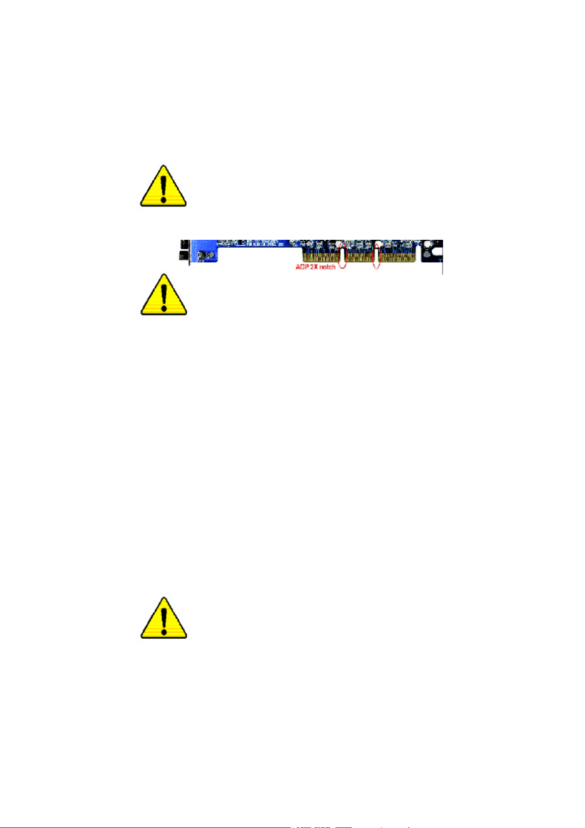
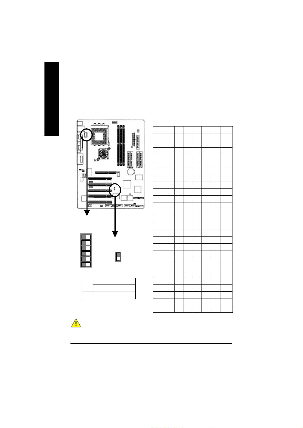
When you installing AGP card, please make sure the following
notice is fully understood and practiced. If your AGP card has
"AGP 4X/8X(1.5V) notch"(show below), please make sure your AGP
card is AGP 4X/8X(1.5V).
AGP 4X/8X notch
Caution: AGP 2X(3.3V) card is not supported by VIA® KT400. You
might experience system unable to boot up normally. Please insert
an AGP 4X/8X(1.5V) card
Example 1: Diamond Vipper V770 golden finger is compatible with
2X/4X mode AGP slot. It can be switched between AGP 2X(3.3V) or 4X
(1.5V) mode by adjusting the jumper. The factory default for this card is
2X(3.3V).
The GA-7VAX / GA-7VAX1394 / GA-7VAXP / GA-7VAXP Ultra
(or any AGP 4X only) motherboards might not function properly, if you
install this card without switching the jumper to 4X(1.5) mode in it.
Example 2: Some ATi Rage 128 Pro graphics cards made by “Power
Color”, the graphics card manufacturer & some SiS 305 cards, their
golden finger is compatible with 2X(3.3V)/4X(1.5V) mode AGP slot, but
they support 2X(3.3V) only. The GA-7VAX / GA-7VAX1394 / GA-7VAXP
/ GA-7VAXP Ultra (or any AGP 4X only) motherboards might not function
properly, If you install this card in it.
Note : Although Gigabyte's AG32S(G) graphics card is based on
ATi Rage 128 Pro chip, the design of AG32S(G) is compliance
with AGP 4X(1.5V) specification. Therefore, AG32S (G)will work
fine with VIA® KT400 based motherboards.
Before you install PCI cards, please remove the Dual BIOS
label from PCI slots if there is one.
Page 2
M The author assumes no responsibility for any errors or
omissions that may appear in this document nor does the
author make a commitment to update the information contained
herein.
M Third-party brands and names are the property of their
respective owners.
M Please do not remove any labels on motherboard, thismay void
the warranty of this motherboard.
M Due to rapid change in technology, some of the specifications
might be out of date before publication of this booklet.
Page 3

Aussch lager Weg 41, 1F, 20537 Ham burg, Germa ny
( description o f the appa ratus, sy stem, installation to whic h it refers)
GA-7VAX / GA-7VAX1394 / GA-7VAXP / GA-7VAXP Ultra
(refere nce to the specifica ti on under wh ich conformity is de clare d)
in accor dance with 89/ 336 EEC-E MC Directive
o EN 55011 Limits and methods of measurement
o EN 55013
o EN 55014 Limits and methods of measurement
o EN 55015 Limits and methods of measurement
o EN 55020
T EN 55022 Limits and methods of measurement
o DIN VDE 0 855
o part 10
o part 12
T CE mark ing
o EN 60065
o EN 60335
of radio disturbance characte ristics of
industrial,sci entific and medical (ISM
high frequency equipment
Limits and methods of measurement
of radio disturbance characte ristics of
broadcast receivers and associated
equipment
of radio disturbance characte ristics of
household electrical appliances,
portable tools and similar electrical
apparatus
of radio disturbance characte ristics of
fluorescent lamps and luminaries
Immunity from radio interferen ce of
broadcast receivers and associated
equipment
of radio disturbance characte ristics of
information technology equipment
Cabled distrib ution systems; Equipment
for receiving and/or distr ibution fr om
sound and television signals
The manufacturer also declar es the confor mity of above mentioned pr oduct
with the actual r equir ed safety standar ds in accor dance with LVD 73/23 EEC
Safety requirements for mains operated
electronic and related apparatus for
household and similar general use
Safety of household and similar
electrical appliances
Declaration of Conformity
We, Man ufacturer /Importer
(full addr ess)
G.B.T. Technolo gy Träding GMbH
decl are that th e pro duct
Mother Board
is in conformity w ith
o EN 61000-3-2*
T EN 60555-2
o EN 61000-3-3* Disturbances in su pply systems cause
T EN 60555-3
T EN 50081-1
T EN 50082-1
o EN 55081-2
o EN 55082-2
o ENV 55104
o EN50091-2
(EC conformity marking)
o EN 60950
o EN 50091-1
Manufacturer/Impor ter
Date : December 2 7, 2002
Disturbances in su pply systems cause
by household appliances and similar
electrical equipment “Harmonics”
by household appliances and similar
electrical equipment “Voltage fluctuations”
Generic emission standard Part 1:
Residual commercial and light industry
Generic immunity standard Part 1:
Residual commercial and light industry
Generic emission standard Part 2:
Industrial environment
Generic emission standard Part 2:
Industrial environment
lmmunity requirements for hou sehold
appliances tools and similar apparatus
EMC requirements for uninterruptible
power syst ems (UPS)
Safety for information technology eq uipment
including electrical bussiness equipment
General and Safety requirments for
uninterruptible power syst ems (UPS)
Signature:
Name:
Timmy Huang
Timmy Huang
Page 4

DECLARATION OF CONFORMITY
Per FCC Part 2 Section 2.1077(a)
Responsible PartName:
Address:
Phone/Fax No:
hereby declares that the product
Product Name:
Model Number:
Conforms to the following specifications:
FCC Part 15, Subpart B, Section 15.107(a) and Section 15.109
(a),Class B Digital Device
Supplementary Information:
This device complies with part 15 of the FCC Rules. Operation is
subject to the following two conditions: (1) This device may not
cause harmful and (2) this device must accept any inference received,
including that may cause undesired operation.
Representative Person’s Name:
Signature:
G.B.T. INC. (U.S.A.)
17358 Railroad Street
City of Industry, CA 91748
(818) 854-9338/ (818) 854-9339
Motherboard
GA-7VAX / GA-7VAX1394
GA-7VAXP/GA-7VAXP Ultra
ERIC LU
Eric Lu
Date:
December 27 ,2002
Page 5

GIGA BYTE obtained of the even t to va lidate the
performance of ATi and Nvidia based graphics cards
(A GP 8X) w ith VIA Chip set base d mother boar ds
running Microsoft operating systems. Certificates of
Validation will be supplied by VIA, ATi and nVIDIA
for GA-7VAXP Ultra; GA-7VAXP; GA-7VAX1394;
GA-7VAX and GA-7VA that successfully passed in
the AGP 8X standard validation
Page 6

Page 7

KT400 Series
AMD Socket A Processor Motherboard
USER'S MANUAL
AMD Athlon™/ Athlon™ XP / Duron™ Socket A Processor Motherboard
Rev. 1202
12ME-7VAXPU-1202
Page 8

Table of Content
English
Item Checklist ..................................................................................... 4
WARNING! .......................................................................................... 4
Chapter 1 Introduction ......................................................................... 5
Chapter 2 Hardware Installation Process .............................................. 9
Chapter 3 BIOS Setup .......................................................................25
Features Summary ......................................................................................... 5
KT400 Series Motherboard Layout ............................................................... 8
Step 1: Install the Central Processing Unit (CPU) ...................................... 10
Step1-1: CPU Speed Setup .......................................................................................10
Step1-2: CPU Installation .......................................................................................... 11
Step1-3:CPU Heat Sink Installation ........................................................................... 12
Step 2: Install memory modules .................................................................. 1 3
Step 3: Install expansion cards .................................................................... 14
Step 4: Connect ribbon cables, cabinet wires, and power supply ............ 15
Step4-1 : I/O Back Panel Introduction ....................................................................... 15
Step4-2 : Connectors Introduction .............................................................................17
The Main Menu (For example: BIOS Ver. : F8) ......................................... 2 6
Standard CM OS Features ........................................................................... 28
Advanced BIOS Features ............................................................................. 31
Integrated Peripherals ................................................................................. 3 3
Power Management Setup .......................................................................... 38
PnP/PCI Configurations ................................................................................ 41
PC Health Status ........................................................................................... 4 2
- 2 -KT400 Series Motherboard
Page 9

Frequency/Voltage Control ........................................................................... 4 4
Top Performance .......................................................................................... 4 7
Load Fail-Safe Defaults ................................................................................ 48
Load Optimized Defaults .............................................................................. 49
Set Supervisor/User Password..................................................................... 50
Save & Exit Setup .......................................................................................... 5 1
Exit Without Saving ....................................................................................... 52
Chapter 4 Technical Reference .......................................................... 55
Block Diagram .............................................................................................. 5 5
Dual BIOS / Q-Flash Introduction ................................................................ 67
@ BIOS Introduction ..................................................................................... 76
Easy TuneTM 4 Introduction .......................................................................... 77
2-/4-/6-Channel Audio Function Introduction ............................................. 78
Chapter 5 Appendix .......................................................................... 85
English
- 3 -
Table of Content
Page 10

Item Checklist
þ The KT400 Series motherboard þ RAID Manual **
English
þ IDE cable x 1/ Floppy cable x 1 þ 4 Port USB Cable x 1
þ IDE cable x 2 ** þ Audio combo Kit x1 **
þ CD for motherboard driver & utility þ IEEE 1394 Cable x1 ***
þ KT400 Series user’s manual o SPD Kit x1
þ I/O Shield þ Quick PC Installation Guide
þ Motherboard Settings Label þ SATA RAID Manual *
þ SATA cable x 2 * o GC-SATA Card * (Optional)
Computer motherboards and expansion cards contain very delicate Integrated Circuit (IC) chips. To
protect them against damage from static electricity, you should follow some precautions whenever you
work on your computer.
(Manual ; SATA cable x1 ; Power cable x 1)
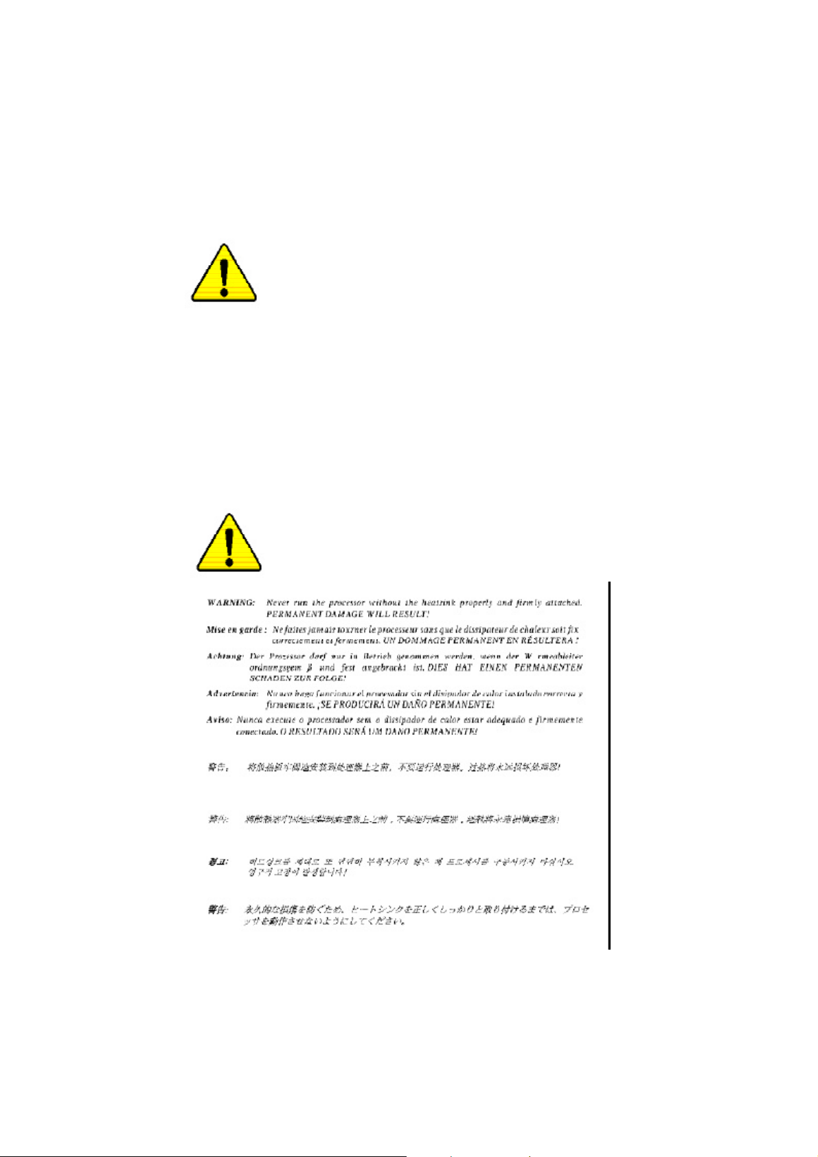
WARNING!
1. Unplug your computer when working on the inside.
2. Use a grounded wrist strap before handling computer components. If you do not have
one, touch both of your hands to a safely grounded object or to a metal object, such as
the power supply case.
3. Hold components by the edges and try not touch the IC chips, leads or connectors, or
other components.
4. Place components on a grounded antistatic pad or on the bag that came with the
components whenever the components are separated from the system.
5. Ensure that the ATX power supply is switched off before you plug in or remove the ATX
power connector on the motherboard.
Installing the motherboard to the chassis…
If the motherboard has mounting holes, but they don’t line up with the holes on the base and there are
no slots to attach the spacers, do not become alarmed you can still attach the spacers to the mounting
holes. Just cut the bottom portion of the spacers (the spacer may be a little hard to cut off, so be careful
of your hands). In this way you can still attach the motherboard to the base without worrying about short
circuits. Sometimes you may need to use the plastic springs to isolate the screw from the motherboard
PCB surface, because the circuit wire may be near by the hole. Be careful, don’t let the screw contact
any printed circuit write or parts on the PCB that are near the fixing hole, otherwise it may damage the
board or cause board malfunctioning.
" * " FOR GA -7VAXP Ul tra Only.
" ** " FOR GA-7VAXP Ultra / GA-7VAXP Only.
" *** " For GA -7VAXP Ultr a / GA -7VAXP / GA- 7VAX1394 Only.
- 4 -KT400 Series Motherboard
Page 11

Chapter 1 Introduction
Features Summary
Form Factor — 30.5cm x 24.3cm ATX size form factor, 4 layers PCB.
Motherboard — KT400 Series:
GA-7VAX / GA-7VAX1394 / GA-7VAXP / GA-7VAXP Ultra
CPU — Socket A processor
AMD AthlonTM/AthlonTM XP/ Duron
128K L1 & 256K/64K L2 cache on die
200/266/333
— Supports 1.4GHz and faster
Chipset — VIA KT400 Memory/AGP/PCI Controller (PAC)
— VIA VT8235 Integrated Peripheral Controller (PSIPC)
Memory — 3 184-pin DDR sockets
— Supports DDR DRAM PC1600/PC2100/PC2700/PC3200
— Supports up to 3.0GB DDR (Max)
— Supports only 2.5V DDR DIMM
I/O Control — IT8705
Slots — 1 AGP slot supports 8X/4X/2X mode(1.5V) & AGP 3.0 Compliant
— 5 PCI slots supports 33MHz & PCI 2.2 compliant
On-Board IDE — 2 IDE controllers provides IDE HDD/CD-ROM (IDE1, IDE2) with
PIO, Bus Master (Ultra DMA33/ATA66/ATA100/ATA133)
operation modes.
— IDE3 and IDE4 Compatible with RAID,Ultra ATA133/100, EIDE **
On-Board Peripherals — 1 Floppy port supports 2 FDD with 360K, 720K,1.2M, 1.44M
and 2.88M bytes.
— 1 Parallel port supports Normal/EPP/ECP mode
— 2 Serial port (COMA & COMB)
— 6 x USB 2.0/1.1 (4 by cable)
— 3 x IEEE1394 by cable ***
— 1 IrDA connector for IR
— 1 Smart Card Reader connector for SCR
Hardware Monitor — CPU/System Fan Revolution detect
— CPU/System temperature detect
— System Voltage Detect
— Thermal shutdown function
<Note 1> FSB333 MHz only support DDR333 DIMM module.
<Note 2> PC3200 only support by Micro, Samsung, Apacer DDR module as we verified, more detail
pls refer to P.99
<Note 1>
MHz FSB and DDR bus speeds
TM
(K7)
<Note 2>
to be continued......
English
" *** " For GA -7VAXP Ultr a / GA -7VAXP / GA- 7VAX1394 Only.
- 5 -
Introduction
Page 12

On-Board Sound — Realtek ALC650 CODEC
English
On-Board USB 2.0 — Built in VIA VT8235 Chipset
On-Board RAID ** — Onbard Promise PDC20276
On-Board SATA RAID * — Onboard Silicon Image Sil3112A
On-Board LAN — RealTek RTL8100BL
On-Board IEEE1394 *** — VT6306
PS/2 Connector — PS/2 Keyboard interface and PS/2 Mouse interace
BIOS — Licensed Award BIOS, 2M bit flash ROM
Additional Features — PS/2 Keyboard power on by password,PS/2 Mouse power on
Overclocking — Over Voltage (DDR/AGP/CPU) by BIOS
— Line Out / 2 front speaker
— Line In / 2 rear speaker(by s/w switch)
— Mic In / center& subwoofer(by s/w switch)
— SPDIF Out /SPDIF In
— CD In / AUX In / Game port
— Supports data striping (RAID 0) or mirroring (RAID 1)
— Supports concurrent dual IDE controller operation
— Supports IDE bus master operation
— Displays status and error checking messages during boot-up
— Mirroring supports automatic background rebuilds
— Features LBA and Extended Interrupt 13 drive translation in
controller onboard BIOS
— Supports Disk striping (RAID0) or DISK Mirroring (RAID1)
— Supports UDMA up to 150 MB/sec
— AIL UDMA and PIO Modes
— Up to 2 SATA Device
— ACPI and ATA/ATAPI6
— Supports Dual BIOS /Q-Flash
— External Modem wake up
— STR(Suspend-To-RAM)
— Wake on LAN (WOL)
— AC Recovery
— Poly fuse for keyboard over-current protection
— USB KB/Mouse wake up from S3
— Supports @BIOS
— Supports EasyTune 4
— Over Clock (DDR/AGP/CPU/PCI) by BIOS
" * " FOR GA -7VAXP Ul tra Only.
" ** " FOR GA-7VAXP Ultra / GA-7VAXP Only.
" *** " For GA -7VAXP Ultr a / GA -7VAXP / GA- 7VAX1394 Only.
- 6 -KT400 Series Motherboard
Page 13

Please set the CPU host frequency in accordance with your processor’s specifications.
We don’t recommend you to set the system bus frequency over the CPU’s specification
because these specific bus frequencies are not the standard specifications for CPU,
chipset and most of the peripherals. Whether your system can run under these specific
bus frequencies properly will depend on your hardware configurations, including CPU,
Chipsets,SDRAM,Cards… .etc.
English
- 7 -
Introduction
Page 14
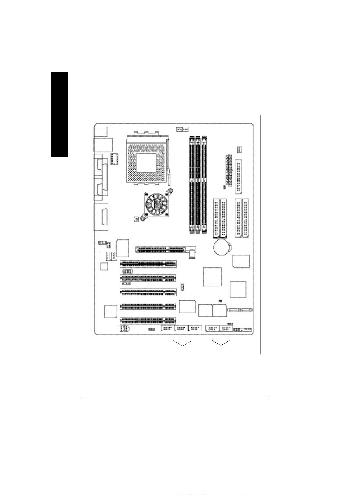
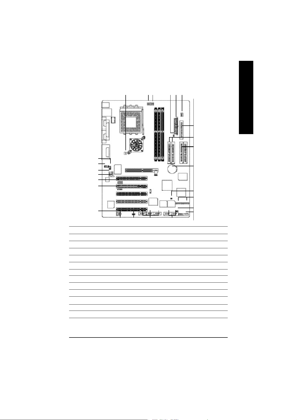
KT400 Series Motherboard Layout
English
KB_MS
USB
COMA
COMB
LINE_OUTMIC_IN
LINE_IN
F_AU DIO
AC 97
LAN
CK _RATIO
LPTGAM E
CD_IN
IT8 7 05
SUR_CEN
AUX_IN
IR
SOCKET A
AGP
DDR400+
KT4 00
AGP 8X
NB_FAN
SCR
K7 Triton 400
CPU
FAN
PCI1
PCI2
SW1
PCI3
SYS
FAN
GA-7VAXP Ultra
DDR1
DDR2
DDR3
VT8 2 35
RAM_LED
IDE1
BATTERY
IDE2
PWR
FAN
ATX
IDE4**
PDC
20 276 **
SIL 311 2 *
FLOPPY
IDE3**
PCI4
PCI5
F2 _1 39 4F1 _1 39 4
IEEE 1394 * **
VT6 3 06
** *
RT L
81 0 0B L
SPDIF_O SPDIF_IN
FSB333
WOL
" * " FOR GA -7VAXP Ul tra Only.
" ** " FOR GA-7VAXP Ultra / GA-7VAXP Only.
" *** " For GA -7VAXP Ultr a / GA -7VAXP / GA- 7VAX1394 Only.
- 8 -KT400 Series Motherboard
MAIN
BIOS
F_U SB1
CI
Back up
BIOS
USB 2.0
S_ATA2*
S_ATA1*
PWR_LED
F_PANEL
F_U SB2F3 -1 3 94
Page 15
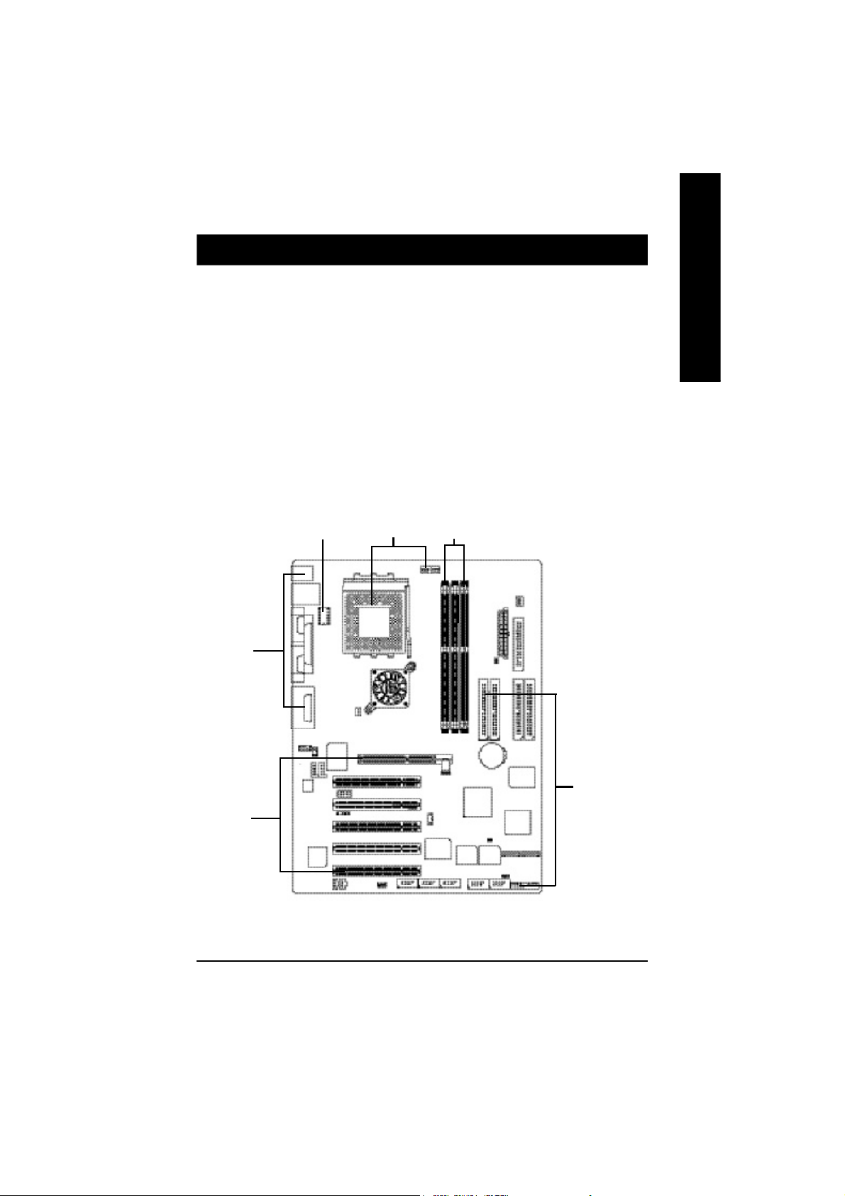
Chapter 2 Hardware Installation Process
To set up your computer, you must complete the following steps:
Step 1- Set Dip Switch (CK_RATIO) and system Switch (SW1)
Step 2- Install the Central Processing Unit (CPU)
Step 3- Install memory modules
Step 4- Install expansion cards
Step 5- Connect ribbon cables, cabinet wires, and power supply
Step 6- Setup BIOS software
Step 7- Install supporting software tools
English
Step 5
Step 4
Step 1
Step 2
Step 3
Step 5
- 9 - Har dware Installation Process
Page 16
Step 1: Install the Central Processing Unit (CPU)
Step1-1: CPU Speed Setup
English
The clock ratio can be switched by CK_RATIO and refer to below table.
Default Setting :
Auto (X X X X X X)
6
O: ON / X :OFF
5
4
2 3
ON
CK_RATIO
1
SW1 CPU CLOCK
100MHz AUTO
1 ON OFF
100MHz : Fix FSB 200MHz CPU
Auto : Support FSB 266/333 MHz CPU
You must set SW1 to 100MHz when
you used FSB 200MHz CPU.
1
SW1
ON
Default Setting: 100MHz
CLK_RATIO
RATIO 1 2 3 4 5 6
AUTO X X X X X X
(Default)
5x O O X O O O
5.5x X O X O O O
6x O X X O O O
6.5x X X X O O O
7x O O O X O O
7.5x X O O X O O
8x O X O X O O
8.5x X X O X O O
9x O O X X O O
9.5x X O X X O O
10x O X X X O O
10.5x X X X X O O
11x O O O O O O
11.5x X O O O O O
12x O X O O O O
12.5x X X O O O O
13x O O X O X O
13.5x X O X O X O
14x O X X O X O
15x O O O X X O
16x O X O X X O
16.5x X X O X X O
17x O O X X X O
18x X O X X X O
MNote: In order to BIOS can auto detecting
when your CP U m utiplier over 18x, plea se
adjust m utiplier swich in CK Raito to "AUTO."
O: ON / X :OFF
- 10 -KT400 Series Motherboard
Page 17
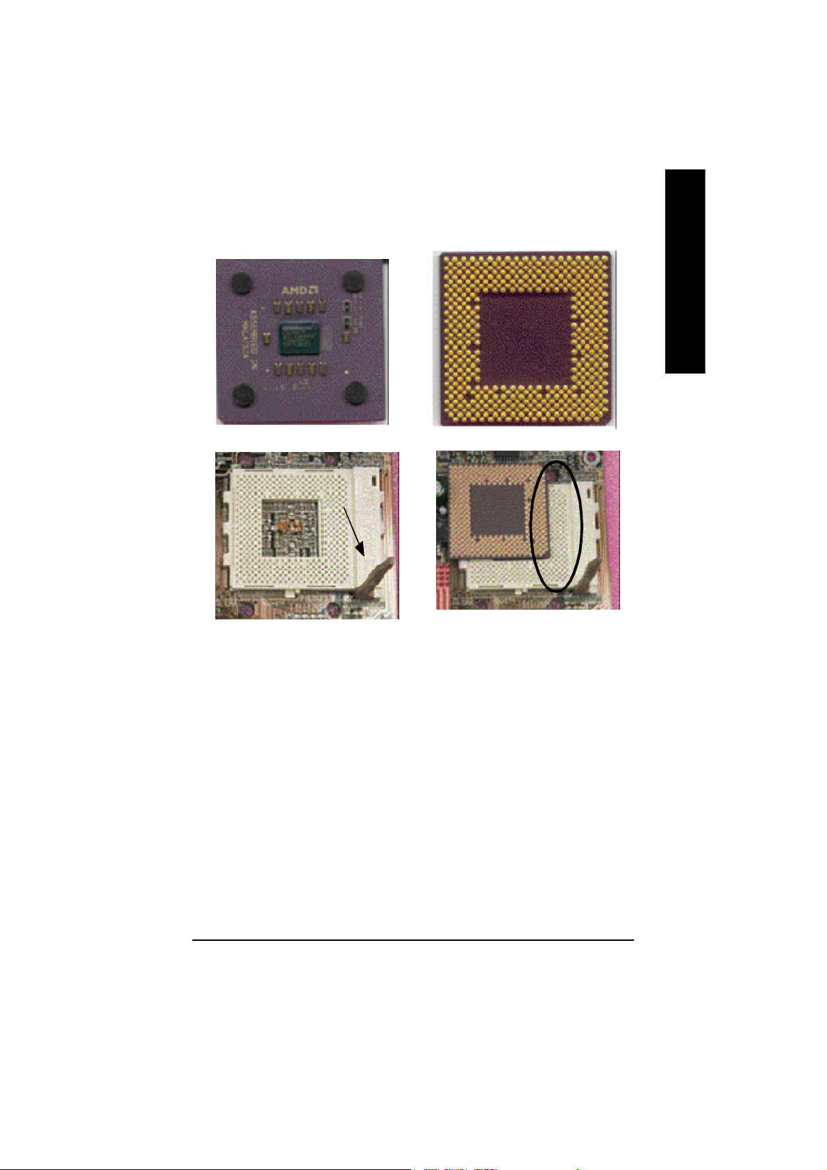
Step1-2: CPU Installation
CPU Top V iew CPU Bottom V iew
Socket Actuation Lever
English
Pin1 indicator
1. Pull up the CPU socket lever
and up to 90-degree angle.
M Please make sure the CPU type is supported by the motherboard.
M If you do not match the CPU socket Pin 1 and CPU cut edge well, it will cause
improper installation. Please change the insert orientation.
2. Locate Pin 1 in the socket and look
for a (golden) cut edge on the CPU
upper corner. Then insert the CPU
into the socket.
- 11 - Hardware Installation Proc ess
Page 18
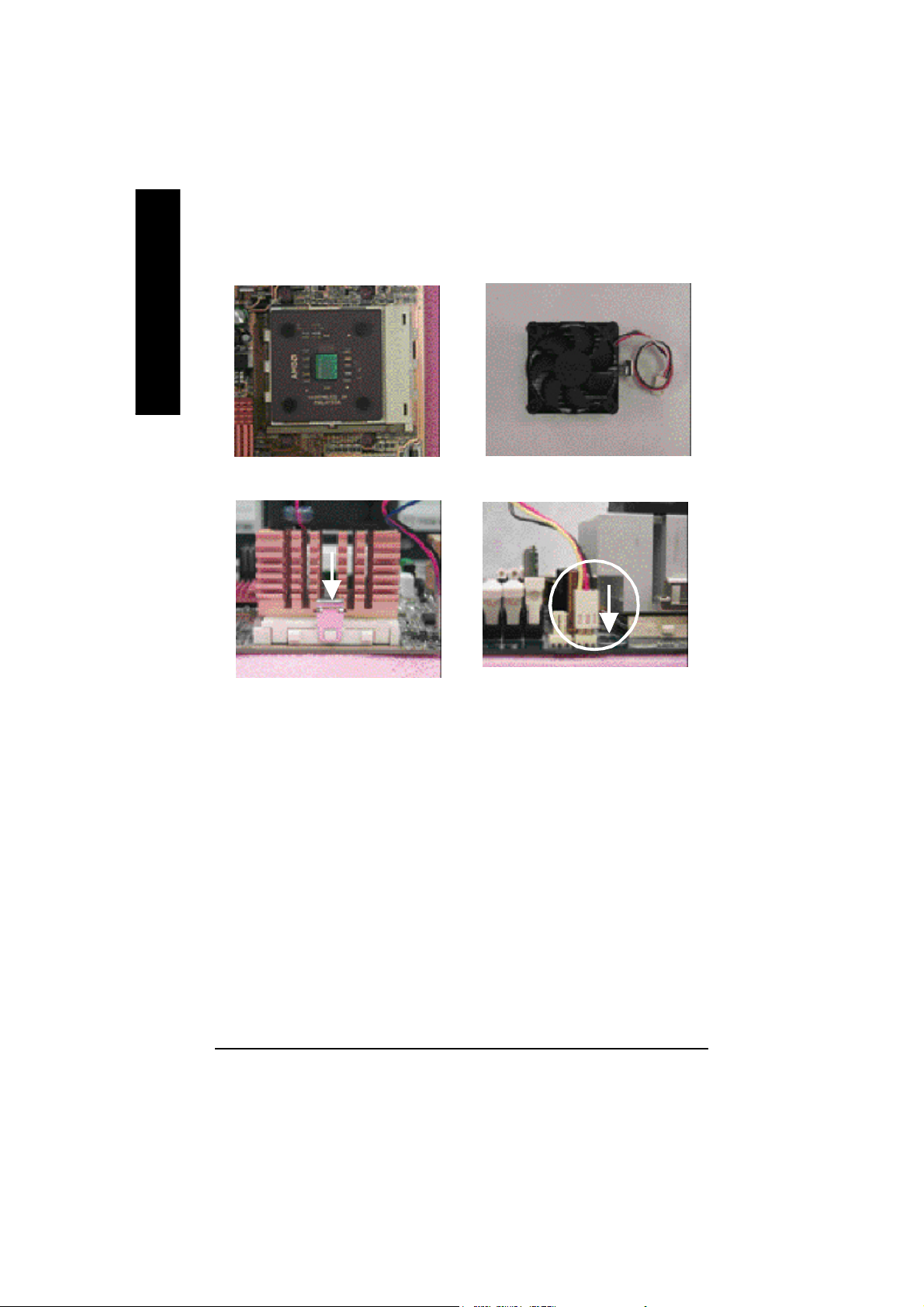
Step1-3:CPU Heat Sink Installation
English
1. Press down the CPU socket
lever and finish CPU installation.
3. Fasten the heatsink supporting-base
onto the CPU socket on the main-
board.
2. Use qualified fan approved by AMD.
4. Make sure the CPU fan is
plugged to the CPU fan connector,
than install complete.
M Please use AMD approved cooling fan.
M We recommend you to apply the thermal paste to provide better heat
conduction between your CPU and heatsink.
M Make sure the CPU fan power cable is plugged in to the CPU fan connector,
this completes the installation.
M Please refer to CPU heat sink user’s manual for more detail installation
procedure.
- 12 -KT400 Series Motherboard
Page 19

Step 2: Install memory modules
The motherboard has 3 dual inline memory module(DIMM) sockets. The BIOS will automatically
detects memory type and size. To install the memory module, just push it vertically into the DIMM Slot.
The DIMM module can only fit in one direction due to the notch. Memory size can vary between
sockets.
Total Memory Sizes With Unbuffered DDR DIMM
Devices used on DIMM 1 DIMMx64/x72 2 DIMMsx64/x72 3 DIMMsx64/x72
64 Mbit (2Mx8x4 banks) 128 MBytes 256 MBytes 384 MBytes
64 Mbit (1Mx16x4 banks) 64 MBytes 128 MBytes 192 MBytes
128 Mbit(4Mx8x4 banks) 256 MBytes 512 MBytes 768 MBytes
128 Mbit(2Mx16x4 banks) 128 MBytes 256 MBytes 384 MBytes
256 Mbit(8Mx8x4 banks) 512 MBytes 1 GBytes 1.5 GBytes
256 Mbit(4Mx16x4 banks) 256 MBytes 512 MBytes 768 MBytes
512 Mbit(16Mx8x4 banks) 1 GBytes 2 GBytes 3 GBytes
512 Mbit(8Mx16x4 banks) 512 MBytes 1 GBytes 1.5 GBytes
DDR
English
1. The DIMM slot has a notch, so the
DIMM memory module can only fit in one direction.
2. Insert the DIMM memory module verticallyinto the
DIMM slot. Then push it down.
3. Close the plastic clip at both edges of theDIMM slots
to lock the DIMM module.
M Reverse the installationsteps when you wish to
remove the DIMM module.
M When STR/DIMM LED is ON, do not install/remove DIMM from socket.
M Please note that the DIMM module can only fit in one direction due to
the one notch. Wrong orientation will cause improper installation.
Please change the insert orientation.
- 13 - Hardware Installation Proc ess
Page 20
DDR Introduction
high performance and cost-effective solution that allows easy adoption for memory vendors, OEMs and
English
system integrators.
SDRAM infrastructure, yet makes awesome advances in solving the system performance bottleneck by
doubling the memory bandwidth. DDR SDRAM will offer a superior solution and migration path from
existing SDRAM designs due to its availability, pricing and overall market support. PC2100 DDR
memory (DDR266) doubles the data rate through reading and writing at both the rising and falling edge of
the clock, achieving data bandwidth 2X greater than PC133 when running with the same DRAM clock
frequency. With peak bandwidth of 2.664 GB per second, DDR memory enables system OEMs to build
high performance and low latency DRAM subsystems that are suitable for servers, workstations, high-
end PC's and value desktop SMA systems. With a core voltage of only 2.5 Volts compared to
conventional SDRAM's 3.3 volts, DDR memory is a compelling solution for small form factor desktops
and notebook applications.
Step 3: Install expansion cards
1. Read the related expansion card’s instruction document before install the expansion card into
2. Remove your computer’s chassis cover, necessary screws and slot bracket from the computer.
3. Press the expansion card firmly into expansion slot in motherboard.
4. Be sure the metal contacts on the card are indeed seated in the slot.
5. Replace the screw to secure the slot bracket of the expansion card.
6. Replace your computer’s chassis cover.
7. Power on the computer, if necessary, setup BIOS utility of expansion card from BIOS.
8. Install related driver from the operating system.
Established on the existing SDRAM industry infrastructure, DDR (Double Data Rate) memory is a
DDR memory is a sensible evolutionary solution for the PC industry that builds on the existing
the computer.
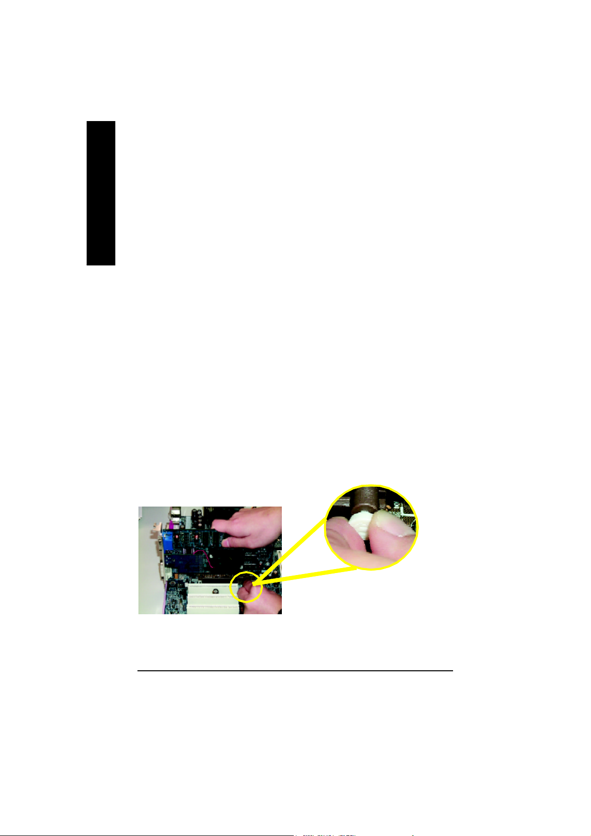
AGP Card
Please carefully pull out the small whitedrawable bar at the end of the AGP slot when
you try to install/ Uninstall the AGP card.
Please align the AGP card to the onboard
AGP slot and press firmly down on the slot .
Make sure your AGP card is locked by the
small white- drawable bar.
- 14 -KT400 Series Motherboard
Page 21
Step 4: Connect ribbon cables, cabinet wires, and power
supply
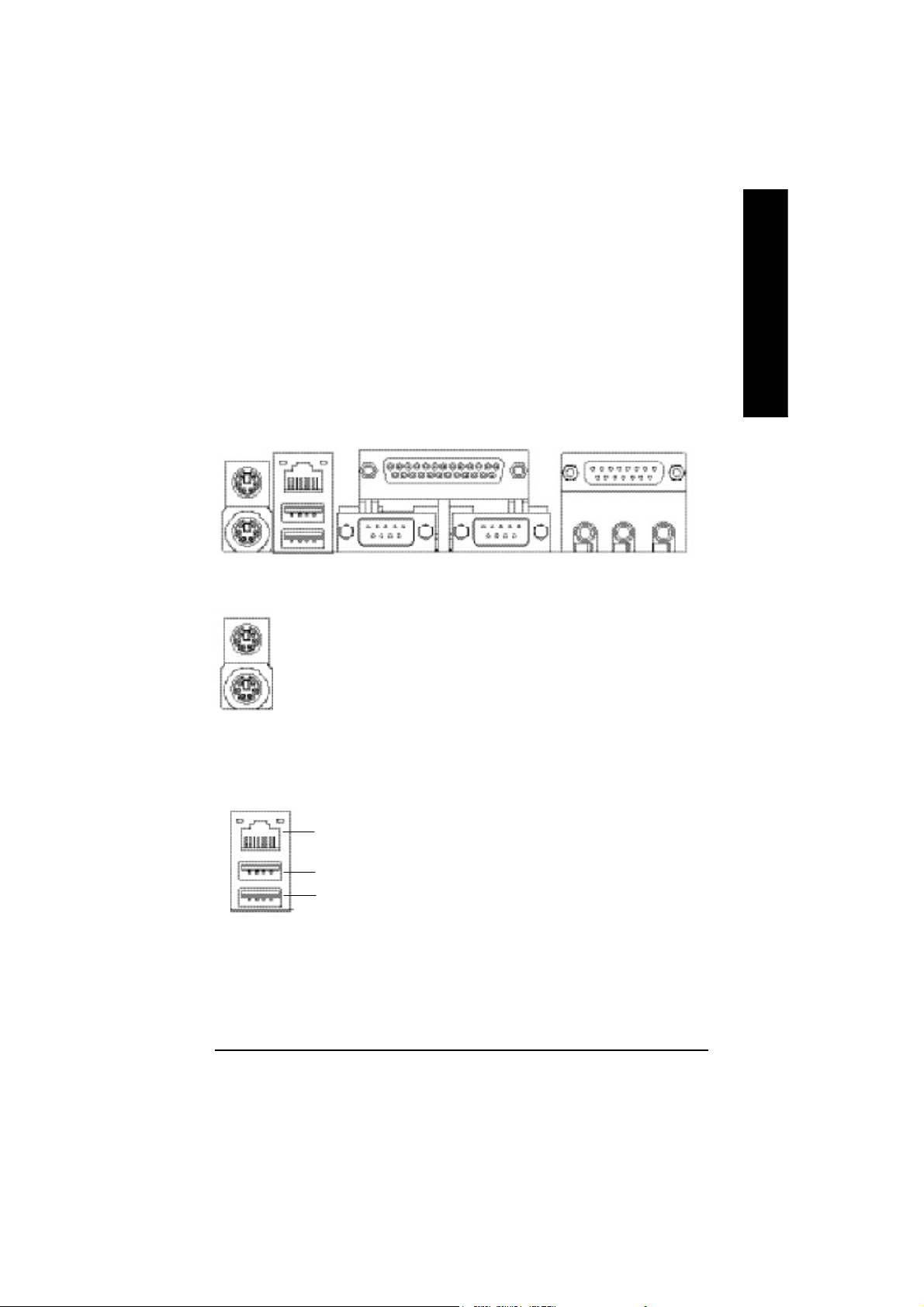
Step4-1 : I/O Back Panel Introduction
English
u
v
w
u PS/2 Keyboard and PS/2 Mouse Connector
PS/2 Mouse Connector
(6 pin Female)
PS/2 Keyboard Connector
(6 pin Female)
v USB/LAN Connector
LAN Connector
USB 1
USB 0
ØThis connector supports standard PS/2
keyboard and PS/2 mouse.
Ø Before you connect your device(s) into USB
connector(s), please make sure your device(s)
such as USB keyboard, mouse, scanner, zip,
speaker..etc. Have a standard USB interface.
Also make sure your OS supports USB
controller. If your OS does not support USB
controller, please contact OS vendor for
possible patch or driver upgrade. For more
information please contact your OS or device(s)
vendors.
x
y
- 15 - Hardware Installation Proc ess
Page 22
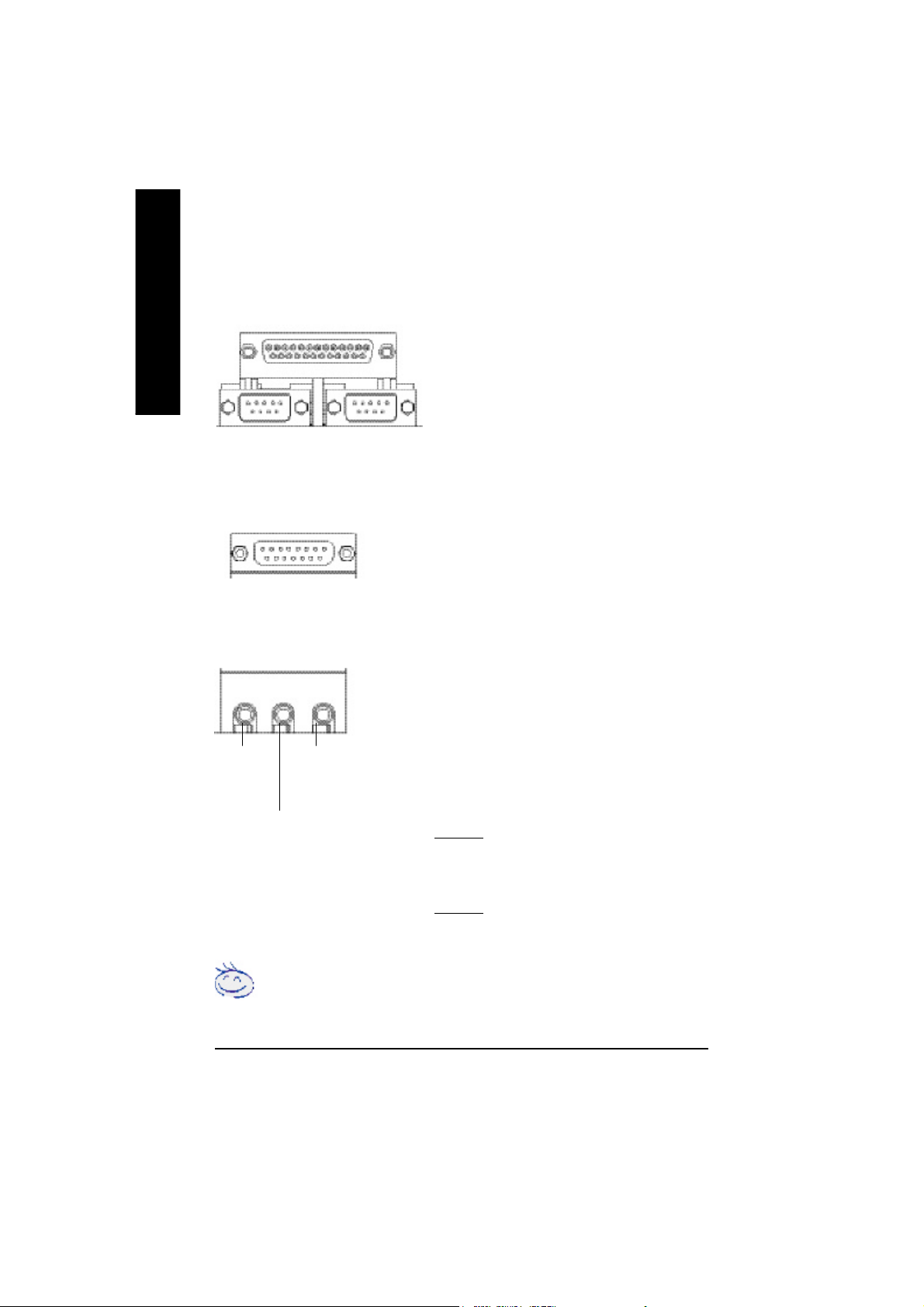
w Parallel Port and Serial Ports (COMA/COMB)
English
Parallel Port
(25 pin Female)
Ø This connector supports 2 standard COM ports and 1
Parallel port. Device like printer can be connected to
Parallel port ; mouse and modem etc can be connected
to Serial ports.
COMA
Serial Ports (9 pin Male)
x Game /MIDI Ports
Joystick/ MIDI (15 pin Female)
y Audio Connectors
Line Out
(Front
Speaker)
MIC In
(Center and Subwoofer)
Line In
(Rear Speaker)
CO MB
Ø This connector supports joystick, MIDI keyboard
and other relate audio devices.
Ø After install onboard audio driver, you may connect
speaker to Line Out jack, micro phone to MIC In jack.
Device like CD-ROM , walkman etc can be connected
to Line-In jack.
Please note:
You are able to use 2-/4-/6- channel audio feature by
S/W selection.
If you want to enable 6-channel function, you have 2
choose for hardware connection.
Method1:
Connect “Front Speaker” to “Line Out”
Connect “Rear Speaker” to “Line In”
Connect “Center and Subwooferr” to “MIC Out “.
Method2:
You can refer to page 21, and contact your nearest dealer
for optional SUR_CEN cable.
If you want the detail information for 2-/4-/6-channel audio setup installation, please
refer to “2-/4-/6-Channel Audio Function Introduction”
- 16 -KT400 Series Motherboard
Page 23
Step4-2 : Connectors Introduction
14
13
15
16
24
19
English
3
514 2
9
8
6
7
12
25
23
17
18
1) CPU_FAN
2) SYS_FAN
3) PWR_FAN
4) NB_FAN
5) ATX_POWER
6) IDE1/IDE2
7) IDE3/IDE4 **
8) FDD
9) RAM_LED
10) F_PANEL
11) PWR_LED
12) BATTERY
2122
13) F_AUDIO
14) SUR_CEN
15) CD_IN
16) AUX_IN
17) SPDIF_O
18) SPDIF-IN
19) I R
20) F_USB1/F_USB2
21) F1_1394/F2_1394/F3_1394***
22) WOL
23) S_ATA1/S_ATA2 *
24) SCR
25) C I
" * " FOR GA -7VAXP Ult ra Only.
" ** " FOR GA-7VAXP Ultra / GA-7VAXP Only.
" *** " For GA -7VAXP Ultr a / GA -7VAXP / GA- 7VAX1394 Only.
- 17 - Hardware Installation Proc ess
11
10
20
Page 24
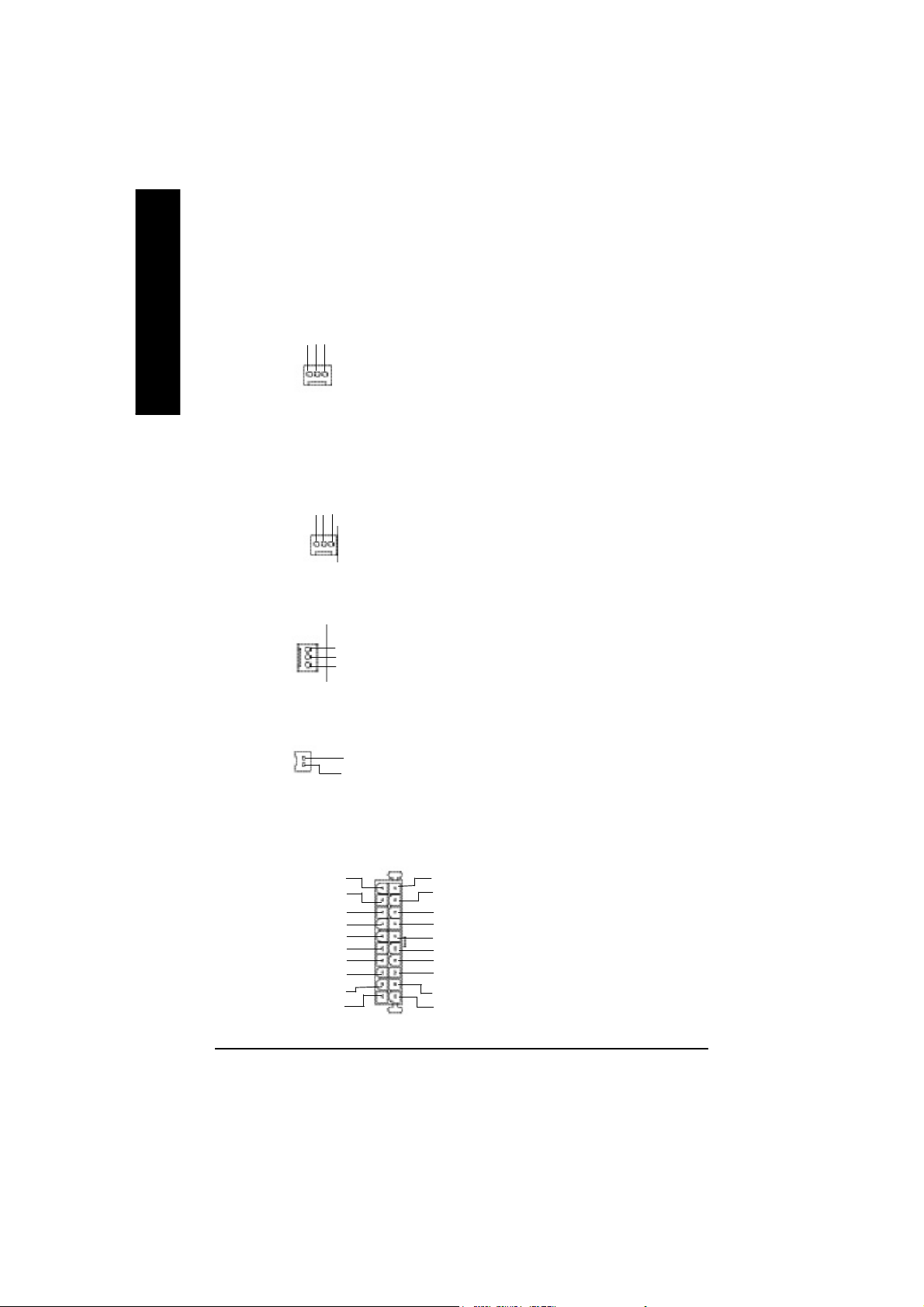
1)CPU_FAN (CPU FAN Connector)
English
Ø Please note, a proper installation of the CPU
cooler is essential to prevent the CPU from
running under abnormal condition or damaged
Sense
+12V
GND
1
by overheating.The CPU fan connector
supports Max. current up to 600 mA.
2)SYS_FAN (System FAN Connector)
+12V
GND
Sense
1
3)PWR_FAN (Power Fan Connector)
1
GND
+12V
N C
4)NB_FAN
GND
1
VCC
5)ATX_POWER (ATX Power)
5V SB (Stand by +5V)
+12V
Power Good
GND
VCC
GND
VCC
GND
3.3V
3.3V
20
GND
GND
-12V
1
Ø This connector allows you to link with the
cooling fan on the system case to lower the
system temperature.
Ø This connector allows you to link with the
cooling fan on the system case to lower the
system temperature.
Ø If you installed wrong direction, the Chip Fan
will not work. Sometimes will damage the Chip
Fan. (Usually black cable is GND)
Ø AC power cord should only be connected to
your power supply unit after ATX power cable
and other related devices are firmly
VCC
connected to the mainboard.
VCC
-5V
GND
GND
PS-ON(Soft On/Off)
3.3V
- 18 -KT400 Series Motherboard
Page 25
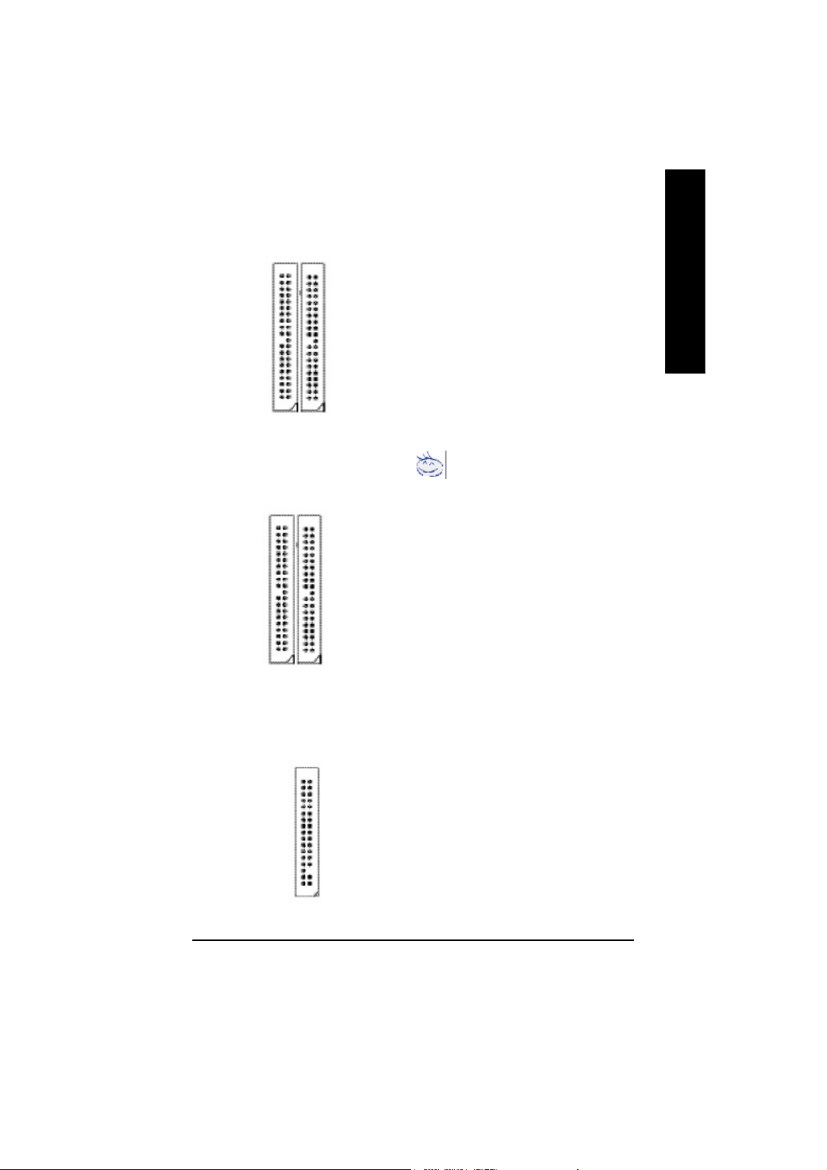
6)IDE1/ IDE2 (IDE1/IDE2 Connector)
Ø Important Notice:
Please connect first harddisk to IDE1 and
connect CDROM to IDE2.
The red stripe of the ribbon cable must be the
same side with the Pin1.
English
IDE1
1
IDE2
1
7)IDE3/IDE4 Connector **
(RAID/ATA133,Green Connector)
IDE4
1
IDE3
1
8)FDD (Floppy Connector)
Important Notice:
1. The rad stripe of the ribbn cable must be the
same side with the Pin1.
2. If you wish to use IDE3 and IDE4, please use
it in unity with BIOS (either RAID or ATA133).
Then, install the correct driver to have proper
operation. For details, please refer to
the PROMISE RAID manual.
Ø Please connect the floppy drive ribbon cables
to FDD. It supports 360K,720K,1.2M,1.44M
and 2.88Mbytes floppy disk types.
The red stripe of the ribbon cable must be the
same side with the Pin1.
1
" ** " FOR GA-7VAXP Ultra / GA-7VAXP Only.
- 19 - Hardware Installation Proc ess
Page 26
9)RAM_LED
English
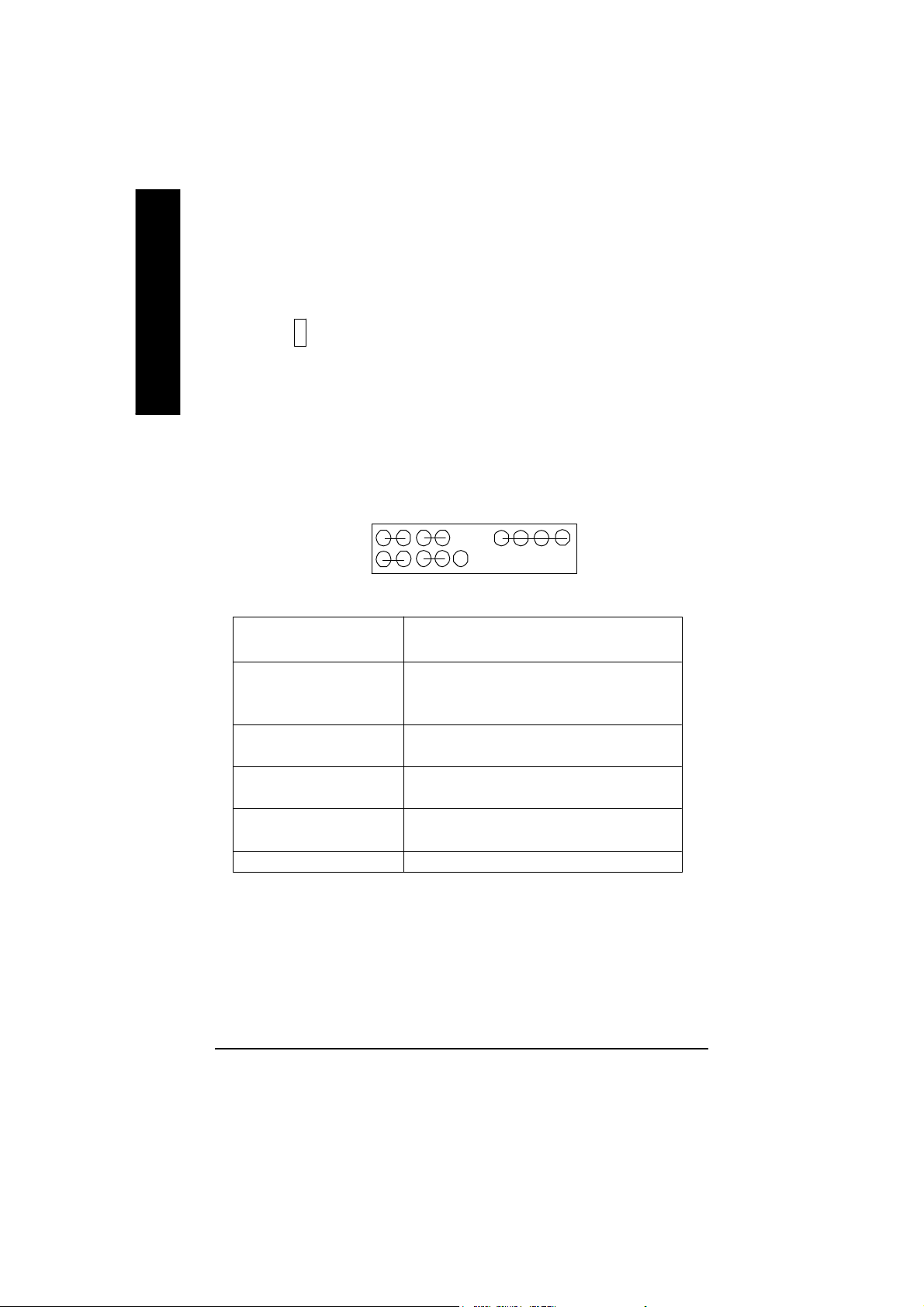
10)F_PANEL (2x10 pins connector)
Ø Do not remove memory modules while
DIMM LED is on. It might cause short or
-
+
other unexpected damages due to the
2.5V stand by voltage. Remove memory
modules only when AC Power cord is
disconnected.
MSG+
1
2
1
1
HD+
HD (IDE Hard Disk Active LED) Pin 1: LED anode(+)
(Blue) Pin 2: LED cathode(-)
SPK (Speaker Connector) Pin 1: VCC(+)
(Amber) Pin 2- Pin 3: NC
RST (Reset Switch) Open: Normal Operation
(Green) Close: Reset Hardware System
PW (Soft Power Connector) Open: Normal Operation
(Red) Close: Power On/Off
MSG(Message LED/Power/ Pin 1: LED anode(+)
Sleep LED)(Yellow) Pin 2: LED cathode(-)
NC (Purple) N C
Ø Please connect the power LED, PC speaker, reset switch and power switch etc of your chassis
front panel to the F_PANEL connector according to the pin assignment above.
PW-
PW+
MSG-
1
1
HD-
RST-
RST+
Pin 4: Data(-)
NC
SPK+
1
SPK-
20
19
- 20 -KT400 Series Motherboard
Page 27
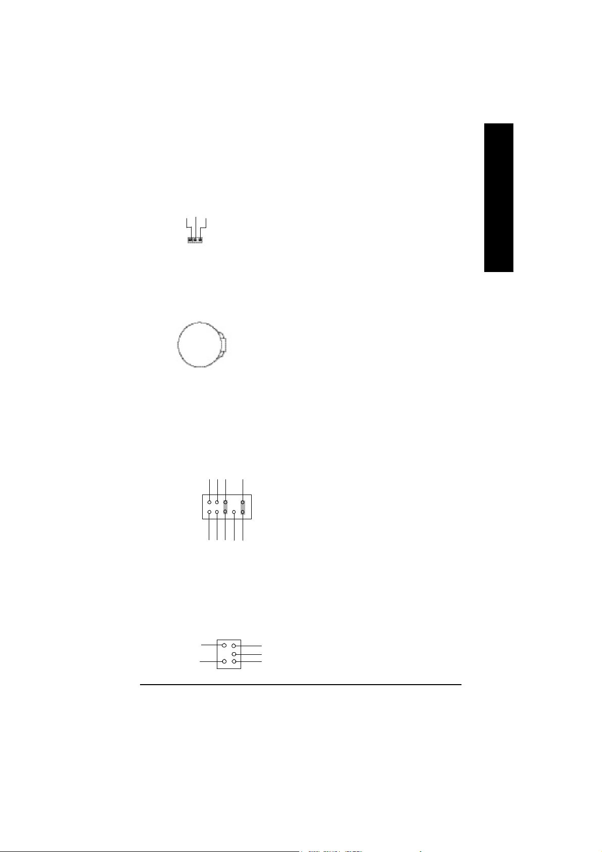
11)PWR_LED
MPD-
MPD-
MPD+
1
Ø PWR_LED is connect with the system power
indicator to indicate whether the system is
on/off. It will blink when the system enters
suspend mode.
If you use dual color LED, power LED will turn
to another color.
English
12)BATTERY
+
13)F_AUDIO (F_AUDIO Connector)
GND
POWER
Rear Audio (R)
Rear Audio (L)
1
MIC
REF
Reserved
Front Audio (L)
Front Audio (R)
CAUTION
v Danger of explosion if battery is incorrectly
replaced.
v Replace only with the same or equivalent
type recommended by the manufacturer.
v Dispose of used batteries according to the
manufacturer’s instructions.
Ø If you want to use Front Audio connector, you
must remove 5-6, 9-10 Jumper.
In order to utilize the front audio header, your
chassis must have front audio connector. Also
please make sure the pin assigment on the
cable is the same as the pin assigment on
the MB header. To find out if the chassis you
are buying support front audio connector,
please contact your dealer.
14) SUR_CEN
BASS_OUT
SUR OUTR
Ø Please contact your nearest dealer for optional
SUR_CEN cable.
CENTER_OUT
GND
SUR OUTL
12
- 21 - Hardware Installation Proc ess
Page 28

15)CD_IN (CD IN)
English
Ø Connect CD-ROM or DVD-ROM audio out
to the connector.
CD-R
1
GND
CD-L
16)AUX_IN ( AUX In Connector)
AUX-R
1
GND
AUX-L
17)SPDIF_O (SPDIFOut)
GND
1
SPDIF OUT
VCC
18)SPDIF_IN
GND
1
SPDIF IN
VCC
Ø Connect other device(such as PCI TV Tunner
audio out)to the connector.
Ø The SPDIF output is capable of providing digital
audio to external speakers or compressed AC3
data to an external Dolby Digital Decoder. Use
this feature only when your stereo system has
digital input function.
Ø Use this feature only when your device has
digital output function.
19)IR
IR Data Input
VCC(+5V)
Ø Be careful with the polarity of the IR
connectorwhile you connect the IR. Please
GND
IR Data Output
1
contact you nearest dealer for optional IR
device.
- 22 -KT400 Series Motherboard
Page 29
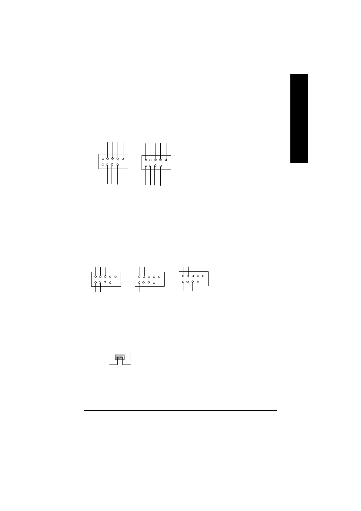
20)F_ USB1 / F_USB2
(Front USB Connector, Yellow )
USB Dy+
USB Over
GND
Current
Power
USB Dy-
Power
USB Dy-
USB Dy+
USB Over
Current
GND
Ø Be careful with the polarity of the front USB
connector. Check the pin assignment
while you connect the front USB cable.
Please contact your nearest dealer for optional
front USB cable.
English
1
Power
USB Dx-
USB Dx+
F_USB1
GND
1
F_USB2
Power
USB Dx-
USB Dx+
GND
21)F1_1394/F2_1394/F3_1394(IEEE1394 Connector,Gray Connector)***
Ø Please Note: Serial interface
standard set by Institute of
GND
Power
GND
TPA2-
GND
PowerPower
TPA0-
TPB0-
1
GND GND
TPA0+
TPB0+
1
F1_1394
22)WOL(Wake on LAN)
1
+5V SB
Signal
GND
GND
TPA1-
GND
TPA1+
F2_1394
Power
TPB1-
Power
TPB1+
GND
1
TPB2-
Electrical and Electronics
Engineers , which has fea
tures like high speed, high
bandwidth and hot plug.
GND
Power
TPA2+
TPB2+
F3_1394
Ø This connector allows the remove servers to
manage the system that installed this
mainboard via your network adapter which
also supports WOL.
" * " FOR GA -7VAXP Ul tra Only.
" ** " FOR GA-7VAXP Ultra / GA-7VAXP Only.
" *** " For GA -7VAXP Ultr a / GA -7VAXP / GA- 7VAX1394 Only.
- 23 - Hardware Installation Proc ess
Page 30

23) S_ATA1/S_ATA2 (Serial ATA Connector) *
English
24)SCR (Smart Card Reader Header)
GND
RXP
7
RXN
GND
TXN
1
TXP
GND
Ø You can connect the Serial ATA device to this
connector, it provides you high speed transfer
rates (150MB/sec).
SCALED
SCARST-
GND
VCC
SCAPWCTL-
1
SCAC4
25) CI (CASE OPEN)
GND
1
Signal
SCAC8
SCAPSNT
SCACLK
SCAIO
Ø This MB supports smart card reader. To en
able smart card reader function an optional smart
card reader box is required. Please contact
your autherized distributor.
Ø This 2 pin connector allows your system to
enable or disable the “case open” item in BIOS
if the system case begin remove.
" * " FOR GA-7VAXP Ultra Only.
- 24 -KT400 Series Motherboard
Page 31

Chapter 3 BIOS Setup
BIOS Setup is an ov er view of the BIOS Setup Pr ogram. The progra m that allow s users to modify
the basic system configuration. This type of information is stored in battery-backed CM OS RAM so
that it retains the Setup information w he n the pow er is turned off.
ENTERING SETUP
After power on the computer, pressing <Del> immediately during POST (Power On Self Test) it will allow you to
enter standard BIOS CMOS SETUP.
If you require more adv anced BIOS settings, please go to “Advanced BIOS” setting menu.To enter
Advanced BIOS setting menu, press “Ctrl+F1” key on the BIOS screen.
CONTROL KEYS
<á> Move to prev ious item
<â> Mov e to next item
<ß> Move to the item in the left hand
<à> Move to the item in the right hand
<Esc> M ain Menu - Quit and not save changes into CMOS Status Page Setup Menu and
Option Page Setup M enu - E xit current page and return to M ain Menu
<+/PgUp> Increase the numer ic value or m ake cha nges
<-/PgDn> Decrease the numeric v al ue or make cha nges
<F1> General hel p, only for Status Page Setup M enu a nd Option Page Setup Menu
<F2> Item help
<F3> Reserv ed
<F4> Reserv ed
<F5> Restore the previous CM OS v alue from CMOS, only for Option Page Setup Menu
<F6> Load the default CMOS value from BIOS default table, only for Option Page Setup
Menu
<F7> Load the S etup Defaults
<F8> Dual BIOS/Q-Flash
<F9> Reserv ed
<F10> Save all the CMOS changes, only for Main M enu
English
- 25 -
BIOS Setup
Page 32

GETTING HELP
The on-line description of the highlighted setup function is displayed at the bottom of the screen.
English
Press F1 to pop up a small help w in dow that describes the appropriate keys to use and the possible
selections for the highlighted item. To exi t the H elp Window pr ess <Esc>.
The Main Menu (For example: BIOS Ver. : F8)
Once you enter Aw ard BIOS CMOS Setup Utility, the M ain Menu (Figure 1) will appear on the screen.
The Main Menu allows you to select from eight setup functions and tw o ex it choices. U se arrow keys to
select among the items and press <Enter> to accept or enter the sub-menu.
Main Menu
Status Page Setup Menu / Op tion Page Setup Menu
CMOS Setup Utility -Copy right (C) 1984-2002 Aw ard Software
}Standard CMOS Features Top Performance
}Advanced BIOS Features Load Fail-Safe Defaults
}Integrated Peripherals Load Optimized Defaults
}Power Management Setup Set Supervisor Password
}PnP/PCI Configurations Set User Password
}PC Health Status Save & Exit Setup
}Frequency/Voltage Control Exit Without Saving
ESC:Quit higf: Select Item
F8:Dual BIOS /Q-Flash F10:Save & Exit Setup
Time, Date, Hard Disk Type...
Figure 1: Main Menu
l Standard CMOS Features
This setup page includes all the items in standard compatible B IOS.
l Advanced BIOS Features
This setup page incl udes a ll the items of Award specia l enhanced features.
l Integrated Peripherals
This setup page i nclud es all onb oard peripherals.
- 26 -KT400 Series Motherboard
Page 33

l Power Management Setup
This setup page in clude s all the items of Green function featur es.
l PnP/PCI Configurations
This setup page includes all the configurations of PCI & Pn P ISA reso urces.
l PC Health Status
This setup page is the Sy s tem auto detect Temperature, voltage, fan, spe ed.
l Frequency/Voltage Control
This setup page is control CPU ’s clock and frequency ratio.
l Top Performance
Top Performance Defaults indicates the value of the system parameters which the sy stem
would be in best performance configuration.
l Load Fai l-Safe Defaul ts
Fail-Safe Defaults indicates the value of the sy stem param eters which the sy stem w ould
be in s afe configur ation.
l Load Optimized Defaults
Optimized Defaults indicates the value of the sy stem param eters which the sy stem w ould
be in b ette r performance con figuration.
l Load Top Performance Defaul ts
Top Performance Defaults indicates the value of the system parameters which the sy stem
would b e in best pe rformance configuration.
l Set Supervis or p as sword
Change, set, or disable p assword. It allows y ou to limit access to the sy stem and Setup,
or just to Setup.
l Set User pas sw ord
Change, set, or disable pass word. It allows y ou to limit acce ss to the s ystem.
l Save & Exit Setup
Save CM OS v alue settings to CMOS and exit setup.
l Exit Without Saving
Abandon all CM OS v alue changes and ex it setup.
English
- 27 -
BIOS Setup
Page 34

Standard CMOS Features
English
CMOS Setup Utility -Copy right (C) 1984-2002 Aw ard Software
Standard CMOS Features
Date (mm:dd:yy) Thu, Feb 21 2002 Item Help
Time (hh:mm:ss) 22:31:24 Menu Level u
} IDE Primary Master [Press Enter None] Change the day, month,
}IDE Primary Slave [Press Enter None] year
}IDE Secondary Master [Press Enter None] <Week>
}IDE Secondary Slave [Press Enter None] Sun. to Sat.
Drive A [1.44M, 3.5”] <Month>
Drive B [None] Jan. to Dec.
Floppy 3 Mode Support [Disabled] <Day>
1 to 31(or maximun allowed
Halt On [All, But Key board] in the month.)
Base Memory 640K <year>
Extended Memory 130048K 1999 to 2098
Total Memory 131072K
higf: Move Enter:Select +/-/PU/PD:Value F10:Save ESC:Ex it F1:General Help
F5:Previous Values F6:Fail-Safe Defaults F7:Optimized Defaults
Figure 2: Standard CMOS Features
F Date
The date format is <week>, <month>, <day>, <y ear>.
8Week The w eek, from Sun to Sat, determined by the BIOS and is display only
8Month The month, Jan. Through Dec.
8Day The day, from 1 to 31 (or the max imum allowed in the month)
8Year The y ear, from 1999 through 2098
F Time
The times format in <hour> <minute> <second>. The time is calculated base on the 24-hour military time clock. For example, 1 p.m. is 13:00:00.
- 28 -KT400 Series Motherboard
Page 35

F IDE Primary M as ter, Slave / Secondary M aster, Slave
The category identifies the types of hard disk from drive C to F that has been installed in the
computer. There are two types: auto type, and manual ty pe. Manual ty pe is user-definable; Auto
type which w ill automatically detect HDD type.
Note that the specifications of your drive must match w ith the driv e table. The hard disk will not work
properly if y ou enter improper information for this category .
If you select User Type, related information w ill be asked to enter to the follow ing items. Enter the
information directly from the keyboard and press <Enter>. Such information should be provided in
the documentation form y our hard disk vendor or the sy stem manufacturer.
8Capacity : The hard disk size. The unit is Mega Bytes.
8Access Mode: The options are: Auto / Large / LBA / Normal.
8Cylinder: The cylinder number of hard disk.
8Head The read / Write head number of hard disk.
8Precomp The cyliner number at w hich the disk driv er changes the write current.
8Landing Zone The cylinder number that the disk driver heads(read/write) are seated when the
disk driv e is parked.
8SECTORS The sector number of each track define on the hard disk.
If a hard disk has not been installed select NON E and press <Enter>.
FDrive A / Drive B
The category iden tifies the ty pes of floppy disk driv e A or driv e B that has been installed in the
computer.
8None No floppy drive installed
8360K, 5.25 “. 5.25 inch PC-type standard drive; 360K byte capacity.
81.2M, 5.25”. 5.25 inch AT-type high-density driv e; 1.2M byte capacity
(3.5 inch w hen 3 Mode is Enabled).
8720K, 3.5 “. 3.5 inch double-sided drive; 720K byte capacity
81.44M, 3.5 “. 3.5 inch double-sided driv e; 1.44M byte capacity .
82.88M, 3.5 “. 3.5 inch double-sided driv e; 2.88M byte capacity .
English
F Floppy 3 Mode Support (for Japan Area)
8Disabled Normal Floppy Driv e. (Default v alue)
8Drive A Enabled 3 mode function of Drive A.
8Drive B Enabled 3 mode function of Drive B.
8Both Drive A & B are 3 mode Floppy Drives.
- 29 -
BIOS Setup
Page 36

F Halt on
English
Me mory
The category is display-only which is determined by POST (Pow er On Self Test) of the BIOS.
The category determine s w hether the computer wil l stop if an error is detected during pow er up.
8NO Errors The sy stem boot w ill not stop for any error that may be detected
and you will be prompted.
8All Errors Whenev er the BIOS detects a non-fatal error the sy stem w ill be stopped.
8All, But Keyboar The system boot w ill not stop for a key board error; it will stop for
all other errors. (Default v alue)
8All, But Diskette The sy stem boot will not stop for a disk error; it w ill stop for all
other errors.
8All, But Disk/Key The sy stem boot will not stop for a keyboard or disk error; it will
stop for all other errors.
Base Memory
The POST of the BIOS will determine the amount of base (or conventional) memory
installed in the sy stem.
The value of the base memory is typical ly 512 K for systems with 512 K memory
installed on the motherboard, or 6 40 K for systems with 640 K or more memory
installed o n the motherboard.
Extende d Memory
The BIOS determines how much extended memory is pres ent during the POST.
This is the amount of memory located above 1 M B in the CPU’s memory
address map.
- 30 -KT400 Series Motherboard
Page 37

Advanced BIOS Features
CMOS Setup Utility -Copy right (C) 1984-2002 Aw ard Software
Advanced BIOS Features
SATA / RAID / SCSI Boot Order * [SCSI] Item Help
(RAID/SCAI Boot Order) ** [RAID, SCSI] Menu Level
First Boot Dev ice [Floppy]
Second Boot Device [HDD-0]
Third Boot Dev ice [CDROM]
Boot Up Floppy Seek [Disabled]
Password Check [Setup]
Flexible AGP 8X [Auto]
Init Display First [AGP]
higf: Move Enter:Select +/-/PU/PD:Value F10:Sav e ESC:Exit F1:General Help
F5:Previous Values F6:Fail-Safe Defaults F7:Optimized Defaults
Figure 3: Adv anced BIOS Features
FSATA / RAID / SCSI Boot Order *
M This feature allows you to select the boot order RAID , SC SI or SATA device.
8RAID Select your boot device priority by RAID.
8SCSI Select your boot device priority by SCSI.(Default value)
8SATA Select your boot device priority by SATA.
English
F RAID / SCSI Boot Order **
M This feature allows you to select the boot order RAID , SC SI device.
8RAID,SCSI Select your boot device priority by RAID.(Default value)
8SCSI,RAID Select your boot device priority by SCSI.
FFirst / Second / Third Boot device
M This feature allow s you to select the boot device priority.
8Floppy Select your boot device priority by Floppy.
8LS120 Select your boot device priority by LS120.
8HDD-0~3 Select y our boot device priority by HDD-0~3.
8SCSI Select your boot device priority by SCSI.
" * " FOR GA-7VAXP Ultra Only. " ** " FOR GA-7VAXP U ltra / GA-7VAXP Only.
- 31 -
BIOS Setup
Page 38

English
FBoot Up Floppy Seek
MDuring POST, BIOS will determine the floppy disk drive installed is 40 or 80 tracks. 360 K type is 40
F Password Check
8CDROM Select your boot device priority by CDROM.
8LAN Select your boot device priority by LAN.
8USB-CDROM Select your boot device priority by USB-CDROM.
8USB-ZIP Select your boot device priority by USB-ZIP.
8USB-FDD Select your boot device priority by USB-FDD.
8USB-HDD Select your boot device priority by USB-HDD.
8ZIP Select your boot device priority by ZIP.
8Disabled Disabled this function.
tracks 720 K, 1.2 M and 1.44 M are all 80 tracks.
8Enabled BIOS searches for floppy disk drive to determine it is 40 or 80 tracks. Note
that BIOS can not tell from 720 K, 1.2 M or 1.44 M driv e ty pe as they are
all 80tracks.
8Disabled BIOS will not search for the type of floppy disk drive by track number. Note
that there w ill not be any warning message if the drive installed is 360 K.
(Default v alue)
8System The system can not boot and can not access to Setup page will be denied
if the correct passw ord is not entered at the prompt.
8Setup The system will boot, but access to Setup w ill be denied if the correct
password is not entered at the prompt. (Default value)
CFlexible AGP 8X
8Auto Automatically set AGP transfer rate according to AGP compatibility and stability .
(Default v alue)
88X Alw ay s set AGP transfer rate to 8X if the 8X mode supported by the AGP card.
84X Set AGP transfer rate to 4X mode no matter what the AGP transfer rate the card is.
FInit Display First
MThis feature allows you to select the first initation of the monitor display from which card, when
you install an AGP VGA card and a PCI VGA card on board.
8PCI Set Init Display First to PCI Slot.
8AGP Set Init Display First to AGP. (Default value)
- 32 -KT400 Series Motherboard
Page 39

Integrated Peripherals
CMOS Setup Utility -Copy right (C) 1984-2002 Aw ard Software
Integrated Peripherals
OnChip IDE Channel0 [Enabled] Item Help
OnChip IDE Channel1 [Enabled] Menu Level
IDE1 Conductor Cable [Auto]
IDE2 Conductor Cable [Auto]
AC97 Audio [Enabled]
USB 1.1 Controller [Enabled]
USB 2.0 Controller [Enabled]
USB Keyboard Support [Disabled]
USB Mouse Support [Disabled]
Onboard H/W LAN [Enabled]
Onboard H/W 1394 *** [Enabled]
Onboard H/W ATA/RAID ** [Enabled]
RAID Controller Function ** [ATA]
Onboard H/W Serial ATA * [Enabled]
Serial ATA Function * [RAID]
Onboard Serial Port 1 [3F8/IRQ4]
Onboard Serial Port 2 [2F8/IRQ3]
UART Mode Select [Normal]
øUR2 Duplex Mode Half
Onboard Parallel Port [378/IRQ7]
Parallel Port Mode [SPP]
Game Port Address [201]
Mdi Port Address [330]
Midi Port IRQ [5]
English
higf: Move Enter:Select +/-/PU/PD:Value F10:Sav e ESC:Exit F1:General Help
F5:Previous Values F6:Fail-Safe Defaults F7:Optimized Defaults
Figure 4: Integrated Peripherals
" * " FOR GA-7VAXP Ultra Only.
" ** " FOR GA-7VAXP Ultra / GA-7VAXP Only.
" *** " For GA-7VAXP Ultra / GA-7VAXP / GA-7VAX1394 Only.
- 33 -
BIOS Setup
Page 40

FOnChip IDE Channel0
MWhen enabled, al low s you to use the onboard primary PC I IDE. If a hard disk controller card is
used, set at Disabled.
English
FOnChip IDE Channel1
MWhen enabled, allows you to use the onboard secondary PCI IDE. If a hard disk controller card is
used, set at Disabled.
FIDE1 Conductor Cable
device
cable
FIDE2 Conductor Cable
device
cable
8Enabled Enable onboard 1st channel IDE port. (Default v alue)
8Disabled Disable onboard 1st channel IDE port.
8Enabled Enable onboard 2nd channel IDE port. (Default value)
8Disabled Disable onboard 2nd channel IDE port.
8Auto Will be automatically detected by BIOS (Default Value)
8ATA66/100/133Set IDE1 Conductor Cable to ATA66/ 100/133 (Plea se make sure y our IDE
and cable is compatible with ATA66/100/133)
8ATA33 Set IDE1 Conductor Cable to ATA33 (Please make sur e your IDE dev ice and
is compatible with ATA33)
8Auto Will be automatically detected by BIOS (Default Value)
8ATA66/100/133Set IDE2 Conductor Cable to ATA66/ 100/133 (Plea se make sure y our IDE
and cable is compatible with ATA66/100/133)
8ATA33 Set IDE2 Conductor Cable to ATA33 (Please make sur e your IDE dev ice and
is compatible with ATA33).
FAC97 Aud io
8Enabled Enabled Onchip AC97 controller. (Default value)
8Disabled Disabled Onchip AC97 controller.
FUSB 1.1 Controller
MDisable this option if y ou are not using the onboard U SB feature.
8Enabled Enabled USB1.1 Controller. (Default value)
8Disabled Disabled USB1.1 Controller.
- 34 -KT400 Series Motherboard
Page 41

FUSB 2.0 Controller
MDisable this option if y ou are not using the onboard U SB 2.0 feature.
8Enabled Enabled USB 2.0 Controller. (Default value)
8Disabled Disabled USB 2.0 Controller.
FUSB Keyboard Support
MWhen a USB keyboard is installed, please set at Enabled.
8Enabled Enabled USB Keyboard Support.
8Disabled Disabled USB Keyboard Support. (Default value)
FUSB Mouse Support
8Enabled Enabled USB Mouse Support.
8Disabled Disabled USB Mouse Support. (Default value)
FOnboard H/W LAN
8Enable Enabled onboard LAN function.(Default v alue)
8Disable Disable onboard LAN function.
FOnboard H/W 1394 ***
8Enable Enabled onboard IEEE 1394 function.(Default value)
8Disable Disabled onboard this function.
English
FOnboard H/W ATA/RAID **
MIf you don't set any HDD Device in ID E3 or 4 bu t enable the function, the
normal message 'MBUltra133 BIOS is not installed becasue th ere are no drives
attached' will come out.'
Ignore this message or set the option disable to make the message disappear.
8Enable Enab led onboard ATA/RAID function. (Default v alue)
8Disable Disabled onboard sound function.
FRAID Controller Function **
8ATA Select onboard RAID chip function as ATA.(Default value)
8RAID Select onboard RAID chip function as RAID.
FOnboard H/W Serial ATA *
8Enabled Enabled Onboard H/W Serial ATA support.(Default value)
8Disabled Disabled Onboard H/W Serial ATA .
" * " FOR GA-7VAXP Ultra Only.
" ** " FOR GA-7VAXP Ultra / GA-7VAXP Only.
" *** " For GA-7VAXP Ultra / GA-7VAXP / GA-7VAX1394 Only.
- 35 -
BIOS Setup
Page 42

FSerial A TA Function *
8RAID Select onboard Serial ATA chip function as RAID.(Default v alue)
8BASE Select onboard Serial ATA chip function as BASE.
English
FOnboard Serial Port 1
FOnboard Serial Port 2
FUART Mode Select
MThis feature allows you to determine which Infra Red(IR) function of Onboard I/O chip)
8Auto BIOS will automatically setup the port 1 address.
83F8/IRQ4 Enable onboard Serial port 1 and address is 3F8,Using IRQ4. (Default value)
82F8/IRQ3 Enable onboard Serial port 1 and address is 2F8,Using IRQ3.
83E8/IRQ4 Enable onboard Serial port 1 and address is 3E8,Using IRQ4.
82E8/IRQ3 Enable onboard Serial port 1 and address is 2E8,Using IRQ3.
8Disabled Disable onboard Serial port 1.
8Auto BIOS will automatically setup the port 2 address.
83F8/IRQ4 Enable onboard Serial port 2 and address is 3F8,Using IRQ4.
82F8/IRQ3 Enable onboard Serial port 2 and address is 2F8,Using IRQ3. (Default Value)
83E8/IRQ4 Enable onboard Serial port 2 and address is 3E8,Using IRQ4.
82E8/IRQ3 Enable onboard Serial port 2 and address is 2E8,Using IRQ3.
8Disabled Disable onboard Serial port 2.
8ASKIR Using as IR and set to ASKIR Mode.
8IrDA Using as IR and set to IrDA Mode.
8Normal Using as standard serial port. (Default Value)
8SCR Using as smart card Interface.
FUR2 Duplex Mode(When UART Mode Select isn’t set [Normal])
MThis feature allows you to select the IR modes.
8Half IR Function Duplex Half. (Default Value)
8Full IR Function Duplex Full.
" * " FOR GA-7VAXP Ultra Only.
- 36 -KT400 Series Motherboard
Page 43

FOnBoard Parallel port
MThis feature allow s you to select from a giv en set of parameters if the parallel port uses the onboard
I/O controller.
8378/IRQ7 Enable onboard LPT port and address is 378, Using IRQ7.(Default Value)
8278/IRQ5 Enable onboard LPT port and address is 278,Using IRQ5.
83BC/IRQ7 Enable onboard LPT port and address is 3BC,Using IRQ7.
8Disabled Disable onboard parallel port.
FParallel Port Mode
MThis feature allow s you to connect with an advanced print via the port mode it supports.
8SPP Using Parallel port as Standard Parallel Port using IRQ7. (Default Value)
8EPP Using Parallel port as Enhanced Parallel Port IRQ5.
8ECP Using Parallel port as Extended Capabilities Port using IRQ7.
8ECP+EPP Using Parallel port as ECP & EPP mode.
FGame Port Address
8Disabled Disabled this function.
8201 Set Game Port Address to 201. (Default Value)
8209 Set Game Port Address to 209.
FMidi Port Address
8Disabled Disabled this function.
8300 Set Midi Port Address to 300.
8330 Set Midi Port Address to 330.(Default Value)
English
FMidi Port IRQ
85 Set 5 for Midi Port IRQ. (Default v alue)
810 Set 10 for Midi Port IRQ.
- 37 -
BIOS Setup
Page 44

Power Management Setup
English
ACPI Suspend Type [S1(POS)] Item Help
øUSB Device Wake-Up From S3 Disabled Menu Lev el
Power LED in S1 state [Blinking]
Soft-Off by PWRBTN [Instant-off]
AC Back Function [Soft-Off]
Keyboard Pow er On [Disabled]
Mouse Pow er On [Disabled]
PME Event Wake Up [Enabled]
ModemRingOn/WakeOnLAN [Enabled]
Resume by Alarm [Disabled]
ø Date(of Month) Alarm Everyday
ø Time(hh:mm:ss) Alarm 0 : 0 : 0
CMOS Setup Utility -Copy right (C) 1984-2002 Aw ard Software
Power Management Setup
higf: Move Enter:Select +/-/PU/PD:Value F10:Sav e ESC:Exit F1:General Help
F5:Previous Values F6:Fail-Safe Defaults F7:Optimized Defaults
Figure 5: Power Management Setup
FACPI Suspend Type
8S1/POS Set suspend type to Pow er On Suspend under ACPI OS(Power On Suspend).
(Default v alue)
8S3/STR Set suspend ty pe to Suspend To RAM under ACPI OS (Suspend To RAM).
FUSB Device Wakeup From S3(When ACPI Suspend Type i s set [S3/STR])
USB device w akeup F rom S3 can be set when ACPI standby state set to S3/STR.
8Enabled USB Device can w akeup sy stem from S3.
8Disabled USB Device can’t wakeup sy stem from S3. (Default v alue)
- 38 -KT400 Series Motherboard
Page 45

FPow er LED in S1 state
8Blinking In standby mode(S1), power LED will blink. (Default Value)
8Dual/Off In standby mode(S1):
a. If use single color LED, pow er LED will turn off.
b. If use dual color LED, pow er LED will turn to another color.
FSoft-off by PWRBTN
8Instant-off Press power button then Power off instantly . (Default value)
8Delay 4 Sec. Press power button 4 sec to Pow er off. Enter suspend if button is pressed less
than 4 sec.
FAC Back Function
8Memory Sy stem power on depends on the status before AC lost.
8Soft-Off Always in Off state w hen AC back. (Default value)
8Full-On Alway s pow er on the system when AC back.
F Keyboard Power On
This feature allow s you to set the method for pow ering-on the system.
The option “Passw ord“ allow s you to set up to 8 alphanumeric characters to pow er-on the system.
The option “Any Key” allows you to touch the keyboard to power on the system.
The option “Key board 98” allow s you to use the standard keyboard 98 to power on the system.
8Password Enter from 1 to 8 characters to set the Key board Pow er On Password.
8Disabled Disabled this function. (Default value)
8Keyboard 98 If y our keyboard have “POWER Key” button, y ou can press the key to
power on y our system.
English
F Mouse Power On
8Disabled Can’t Pow er on sy stem by Mouse Event. (Default v alue)
8Enabled Can Power on sy stem by Mouse Event.
- 39 -
BIOS Setup
Page 46

FPME Event Wake up
English
FM odem Ring On/ WakeOnLAN (When AC Back Function is set to [Soft-Off])
FResume by Alarm
M When set at Enabled, any PCI-PM event awakes the system from a PCI-PM controlled
state.
M This feature requires an ATX pow er supply that provides at least 1A on the
+5VSB lead.
8Disabled Disabled PME Event Wake up function.
8Enabled Enabled PME Event Wake up function. (Default Value)
M You can enable wake on LAN feature by the "ModemRingOn/WakeOnLAN" or "PME Event Wake
up" when the M/B has "WOL" onboard connector. Only enabled the feature by "PME Event Wake
up".
M An incoming call via modem awakes the system from its soft-off mode.
M When set at Enabled, an input signal comes from the other client.
Server on the LAN awaks the system from a soft off state if connected over LAN.
8Disabled Disabled Modem Ring On / Wake On LAN function.
8Enabled Enabled Modem Ring On / Wake On LAN function. (Default Value)
You can set "Resume by Alarm" item to enabled and key in Data/time to power on system.
8Disabled Disable this function. (Default Value)
8Enabled Enable alarm function to POWER ON sy stem.
If RTC Alarm Lead To Pow er On is Enabled.
Date ( of Month) Alarm : Ev ery day, 1~31
Time ( hh: mm: ss) Alarm : (0~23) : (0~59) : (0~59)
- 40 -KT400 Series Motherboard
Page 47

PnP/PCI Configurations
CMOS Setup Utility -Copy right (C) 1984-2002 Aw ard Software
PnP/PCI Configurations
PCI1/PCI5 IRQ Assignment [Auto] Item Help
PCI2 IRQ Assignment [Auto] Menu Lev el
PCI3 IRQ Assignment [Auto]
PCI4 IRQ Assignment [Auto]
higf: Move Enter:Select +/-/PU/PD:Value F10:Save ESC:Ex it F1:General Help
F5:Previous Values F6:Fail-Safe Defaults F7:Optimized Defaults
Figure 6: PnP/PCI Configurations
FPCI1/PCI5 IRQ Assignment
8Auto Auto assign IRQ to PCI 1/ PCI 5. (Default v alue)
83,4,5,7,9.,10,11,12,14,15 Set 3,4,5,7,9,10,11,12,14,15 to PCI1/ PCI5.
FPCI2 IRQ Ass ignment
8Auto Auto assign IRQ to PCI 2. (Default value)
83,4,5,7,9.,10,11,12,14,15 Set 3,4,5,7,9,10,11,12,14,15 to PCI2.
English
FPCI3 IRQ Assignment
8Auto Auto assign IRQ to PCI 3. (Default value)
83,4,5,7,9.,10,11,12,14,15 Set 3,4,5,7,9,10,11,12,14,15 to PCI3.
FPCI4 IRQ Assignment
8Auto Auto assign IRQ to PCI 4. (Default value)
83,4,5,7,9.,10,11,12,14,15 Set 3,4,5,7,9,10,11,12,14,15 to PCI4.
- 41 -
BIOS Setup
Page 48

PC Health Status
English
Reset Case Open Status [Disabled] Item Help
Case Opened No Menu Lev el
VCORE 1.772V
DDRVtt 1.248V
+3.3V 3.280V
+ 5V 4.919 V
+12V 11.968V
5VSB 5.053V
Current System Temperature 37°C
Current CPU FAN Speed 6250 RPM
Current SYSTEM FAN speed 0 RPM
CPU FAN Fail Warning [Disabled]
SYSTEM FAN Fail Warning [Disabled]
CPU Shutdown Temperature [Disabled]
Current CPU Temperature 52°C/125°F
CMOS Setup Utility -Copy right (C) 1984-2002 Aw ard Software
PC Health Status
higf: Move Enter:Select +/-/PU/PD:Value F10:Sav e ESC:Exit F1:General Help
F5:Previous Values F6:Fail-Safe Defaults F7:Optimized Defaults
Figure7: PC Health Status
CReset Case Open Status
CCase Opened
If the case is closed, "Case Opened" w ill show "No".
If the case have been opened, "Case Opened" w ill show "Yes".
If y ou want to reset "Case Opened" value, set "Reset Case Open Status" to
"Enabled" and sav e CMOS, y our computer w ill restart.
FCurrent Voltage (V) VCORE / DDRVtt/ +3.3V/ +5V / +12V / 5VSB
Detect sy stem’s voltage status automatically.
- 42 -KT400 Series Motherboard
Page 49

FCurrent CPU FAN / SYSTEM FAN Speed (RPM)
Detect Fan speed status automatically.
F Fan Fail Warni ng ( CPU / SYSTEM)
8Disabled Don’t monitor current fan speed. (Default value)
8Enabled Alarm when stops.
FCPU Shutdown Temperature
8Enabled System shutdow n w hen current CPU temperature over than 110oC
8Disabled Don’t monitor current temperature.(Default v alue)
FCurrent CPU Temperature (°C)
Detect CPU Temp. automatically.
English
- 43 -
BIOS Setup
Page 50

Frequency/Voltage Control
English
Spread spectrum Modulated [Auto] Menu Lev el
CPU Host Clock Control [Disable] Item Help
øCPU Host Frequency(MHz) 100
øPCI/AGP Frequency (MHz) 33/66
DRAM Clock(MHz) [Auto]
AGP mode support [Auto]
CPU Voltage Control [Auto]
AGP OverVoltage Control [Auto]
DIMM OverVoltage Control [Auto]
øThose items will be available when " C PU H ost Clock C ontrol" is set to Enabled.
F Spread spectrum Modul ated
CMOS Setup Utility -Copy right (C) 1984-2002 Aw ard Software
Frequency/Voltage Control
higf: Move Enter:Select +/-/PU/PD:Value F10:Sav e ESC:Exit F1:General Help
F5:Previous Values F6:Fail-Safe Defaults F7:Optimized Defaults
Figure 8: Frequency /Voltage Control
8Auto Set clock spread spectrum by auto.(Default v alue)
8Disabled Disable clock spread spectrum.
8Enabled Enable clock spread spectrum.
F CPU Host Clock Control
Note: If system hangs up before enter CMOS setup utility, wait for 20 sec for times out reboot . When
time out occur, system w ill reset and run at CPU default Host clock at nex t boot.
8Disable Disable CPU Host Clock Control.(Default value)
8Enable Enable CPU Host Clock Control.
F CPU Host Frequency (MHz) (By switch SW1)
8100 Set CPU Host Clock to 100MHz~132MHz.
8133 Set CPU Host Clock to 133MHz~165MHz.
8166 Set CPU Host Clock to 166MHz~200MHz.
- 44 -KT400 Series Motherboard
Page 51

FPCI/AG P Frequency (MHz)
8The values depend on CPU Host Frequency(Mhz) .
FDRAM Clock (MHz)
M Wrong frequency may make system can’t boot. Clear CMOS to ov ercome wrong frequency issue.
8Please set DRAM Clock according to y our requirement.
If you use DDR200 DRAM module, please set “DRAM Clock(MHz)” to “100-DDR200”. If y ou use
DDR333 DRAM module, please set “DRAM Clock(MHz)” to “166-DDR333”.
Incorrect using it may cause your system broken. For power End-User use only!
8Auto Auto setting Memory frequency. (Default value)
FAGP mode support
8Auto Auto setting AGP transfer rate.(Default value)
88X Set AGP 8X mode support.
84X Set AGP 4X mode support.
82X Set AGP 2X mode support.
81X Set AGP 1X mode support.
M An AGP 4X graphic card is only allowed to run at AGP4X m ode, even it is set to AGP 8X
mode.
English
FCPU OverVoltage Control
Increase CPU voltage may g et stable for Over_Clock. But it may dama ge to CPU when enable this
feature.
8Auto Supply voltage as CPU reguired. (Default value)
8+5% / +7.5% / +10% Increase voltage range as user selected.
FAGP OverVoltage Control
Increase AGP voltage may get stable for Over_Clock. But it may damage to AGP Card when enable this
feature.
8Auto Supply voltage as AGP Card reguired. (Default value)
8+0.1V~+.03V Set AGP voltage from 1.6V~1.8V.
- 45 -
BIOS Setup
Page 52

FDIM M OverVoltage Control
Increase DRAM v oltage may get stabl e for Over _Clock. But it may damage to DRAM module w hen
enable this feature.
English
8Auto Supply voltage as DRAM module reguired. (Default v alue)
8+0.1V~+.03V Set DIMM voltage from 2.6V~2.8V.
- 46 -KT400 Series Motherboard
Page 53

Top Performance
CMOS Setup Utility -Copy right (C) 1984-2002 Award Software
}Standard CMOS Features Top Performance
}Advanced BIOS Features Load Fail-Safe Defaults
}Integrated Peripherals Load Optimized Defaults
}Power Management Setup Set Supervisor Password
}PnP/PCI Configurations Set User Password
}PC Health Status Save & Exit Setup
}Frequency/Voltage Control Exit Without Saving
ESC:Quit higf: Select Item
F8:Dual BIOS /Q-Flash F10:Save & Exit Setup
Top Pe rformance
If you wish to maximize the performance of yo ur sy stem, set "Top Performance" as "Enabled" .
8Disabled Disable this function. (Default Value)
8Enabled Enable Top Performance function.
Disabled......... .......... [ n ]
Enabled......... ..........[ ]
hi: Move ENTER: Accept
ESC: Abort
Figure 9: Top Performance
English
You must check whether your RAM&CPU support over clock when y ou set "Top Performance"
to " Enabled"
- 47 -
BIOS Setup
Page 54

Load Fail-Safe Defaults
English
F Load Fail-Safe Defaults
CMOS Setup Utility -Copy right (C) 1984-2002 Award Software
}Standard CMOS Features Top Performance
}Advanced BIOS Features Load Fail-Safe Defaults
}Integrated Peripherals Load Optimized Defaults
}Power Management Setup Set Supervisor Password
}PnP/PCI Configurations Set User Password
}PC Health Status Save & Exit Setup
Figure 11: Load Fail-Safe Defaults
}Frequency/Voltage Control Exit Without Saving
ESC:Quit higf: Select Item
F8:Dual BIOS /Q-Flash F10:Save & Exit Setup
Fail-Safe defaults contain the most appropriate valu es of the system parameters that allow
minimum sy stem pe rformance.
Load Fail-Safe Defaults? (Y/N)?N
Load Fail-Safe Defaults
Figure 11: Load Fail-Safe Defaults
- 48 -KT400 Series Motherboard
Page 55

Load Optimized Defaults
CMOS Setup Utility -Copy right (C) 1984-2002 Award Software
}Standard CMOS Features Top Performance
}Advanced BIOS Features Load Fail-Safe Defaults
}Integrated Peripherals Load Optimized Defaults
}Power Management Setup Set Supervisor Password
}PnP/PCI Configurations Set User Password
}PC Health Status Save & Exit Setup
}Frequency/Voltage Control Exit Without Saving
ESC:Quit higf: Select Item
F8:Dual BIOS /Q-Flash F10:Save & Exit Setup
Figure 11: Load Fail-Safe Defaults
F Load Optimized Defaults
Selecting this field loads the factory d efaults for BIOS and C hip set Features which the
system automatically detects.
Load Optimized Defaults? (Y/N)?N
Load Optimized Defaults
Figure 12: Load Optimized Defaults
English
- 49 -
BIOS Setup
Page 56

Set Supervisor/User Password
English
When y ou select this func tion, the follow ing message w ill appear at the center of the screen to
assist you in creating a pass word.
Type the pa ssword, up to eig ht characters, and pr ess <Enter>. You w ill be asked to confirm the
password. Ty pe the passwor d aga in and press <Enter>. You may also pres s <Esc> to abort the
selection and n ot enter a password.
To disable p assword, just press <Enter> when y ou are prompted to enter pa ssword. A message
“PASSWORD DISABLED” w ill appear to confirm the passw ord being disabled. Once the password
is disabled, the system w ill boot and y ou can enter Setup freely.
The BIOS Setup program allows you to specify two separate passwords: a S U PERVISOR PASS-
WORD and a USER PASSWORD. When disabled, anyone m ay access all BIOS Setup program
function. When enabled, the Superv is or passw ord is required for entering the BIOS Setup program
and having full configuration fields, the User pass w ord is required to access only basic items.
If you select “System” at “Security Option” in Advance BIOS Features Menu, you w ill be prompted
for the password ev ery time the system is rebooted or any time y ou try to enter Setup Menu.
If you select “Setup” at “Security Option” in Adv ance BIOS Features Me nu, y ou will be pro mpted
only w hen y ou try to enter Setup.
CMOS Setup Utility -Copy right (C) 1984-2002 Award Software
}Standard CMOS Features Top Performance
}Advanced BIOS Features Load Fail-Safe Defaults
}Integrated Peripherals Load Optimized Defaults
}Power Management Setup Set Supervisor Password
}PnP/PCI Configurations Set User Password
Figure 11: Load Fail-Safe Defaults
}PC Health Status Save & Exit Setup
}Frequency/Voltage Control Exit Without Saving
ESC:Quit higf: Select Item
F8:Dual BIOS /Q-Flash F10:Save & Exit Setup
Enter Password:
Change/Set/Disable Password
Figure 13: Password Setting
- 50 -KT400 Series Motherboard
Page 57

Save & Exit Setup
CMOS Setup Utility -Copy right (C) 1984-2002 Award Software
}Standard CMOS Features Top Performance
}Advanced BIOS Features Load Fail-Safe Defaults
}Integrated Peripherals Load Optimized Defaults
}Power Management Setup Set Supervisor Password
}PnP/PCI Configurations Set User Password
}PC Health Status Save & Exit Setup
}Frequency/Voltage Control Exit Without Saving
ESC:Quit higf: Select Item
F8:Dual BIOS /Q-Flash F10:Save & Exit Setup
Type “Y” w ill quit the Setup U tility and save the user setup value to RTC C M OS.
Type “N” w ill return to Setup Utility.
Save to CMOS and EXIT (Y/N)? Y
Save Data to CMOS
Figure 14: Sav e & Ex it Setup
English
- 51 -
BIOS Setup
Page 58

Exit Without Saving
English
Type “Y” w ill quit the Setup Utility without sav ing to RTC CMOS.
Type “N” w ill return to Setup Utility.
CMOS Setup Utility -Copy right (C) 1984-2002 Award Software
}Standard CMOS Features Top Performance
}Advanced BIOS Features Load Fail-Safe Defaults
}Integrated Peripherals Load Optimized Defaults
}Power Management Setup Set Supervisor Password
}PnP/PCI Configurations Set User Password
}PC Health Status Save & Exit Setup
}Frequency/Voltage Control Exit Without Saving
ESC:Quit higf: Select Item
F8:Dual BIOS /Q-Flash F10:Save & Exit Setup
Quit Without Saving (Y/N)? N
Abandon all Data
Figure 15: Ex it Without Saving
- 52 -KT400 Series Motherboard
Page 59

English
- 53 -
BIOS Setup
Page 60

English
- 54 -KT400 Series Motherboard
Page 61

Chapter 4 Technical Reference
Block Diagram
English
TM
AMD-K7
AGP 2X/4X/8X
AGPCLK
(66MHz)
5 PCI
RTL8100BL
RJ45
AC97 Link
AC97
CODEC
PCICLK
(33MHz)
MIC
LINE-IN
LINE-OUT
PCICLK (33MHz)
USBCLK (48MHz)
14.318 MHz
33 MHz
" * " FOR GA-7VAXP Ultra Only.
" ** " FOR GA-7VAXP Ultra / GA-7VAXP Only.
" *** " For GA-7VAXP Ultra / GA-7VAXP / GA-7VAX1394 Only.
VIA
VT8377
VIA
VT8235
6 USB
Ports
CLK
GEN
System Bus100/133/166 MHz
100/133/166 MHz
48 MHz
LPC BUS
ATA33/66
/100/133
IDE Channels
CPUCLK+/- (100/133/166MHz)
DDR RAM
HCLK+/- (100MHz)
MCHCLK (100/133/166MHz)
66 MHz
33 MHz
14.318 MHz
PDC20276 **
(RAID133)
IT8705
24 MHz
33 MHz
SIL3112 *
S_ATA1*
HCLK+/- (100MHz)
CPUCLK+/- (100/133/166MHz)
AGPCLK (66MHz)
MCHCLK (100/133/166mHz)
ICH3V66 (66MHz)
3 IEEE1394 ***
IDE3 **
IDE4 **
SCR
S_ATA2*
Game Port
Floppy
LPT Port
PS/2
KB/Mouse
COM
Ports
- 55 -
Technical Reference
Page 62

BIOS F lash Pr ocedureyte @BIOS
TM
Program to flash BIOS.
English
We use GA-7VTX motherboar d and Flash841 BIOS flash utility as exa mple.
Please flash the BIOS according to the following pro cedures i f you are now under the DOS mode.
Flash BIOS Procedure:
STEP 1:
(1) Please make sure your system has installed the extraction utility such as wi nzip or pkunzip.
STEP 2: Make a DOS boot diskette. (See example: Window s 98 O.S.)
Beware: Window s ME/2000 are not allow ed to make a DOS boot diskette.
(1) With an availab le floppy disk in the floppy drive. Please leav e the diskette " UN-write
Method 1:
Firstly you hav e to install the ex traction u tility su ch as w inzip or pkunzip for unzip the files.
Both of these utilities are av ailable on many shareware download pages like http://ww w.cnet.com
protected" ty pe. Double click the "My Computer" icon from Desk top, the n click "3.5 diskette
(A)" and right click to select "Forma t (M )"
- 56 -KT400 Series Motherboard
Page 63

(2) Select the "Quick (eras e)" for Format Ty pe, and p ick both " Display summary when fini shed"
and "C opy system files", after that pr ess "Start". That w ill format the floppy and transfer the
needed sys tem fi les to it.
Beware: This pro cedure will erase all the prior data on that floppy, so plea se proceed
accordingly .
(3) After the floppy has bee n formatted co mpletel y, please press " Clo se".
English
- 57 -
Technical Reference
Page 64

STEP 3: Download BIOS and BIOS utility program.
(1) Please go to Gigabyte w ebsite http: //w ww.gig abyte.com.tw/index .html, and click "Support".
English
(2) From Support zone, click the " Motherboards BIOS & Driv ers" .
- 58 -KT400 Series Motherboard
Page 65

(3) We use GA-7VTX motherboard as e xample. P lease select GA-7VTX by Model or C hipset
optional menu to obtain BI OS flash files.
(4) Select an appropriate BI OS v ersion (For ex ample: F4), and click to dow nload the file. It will
pop up a file dow nload sc reen, then select the "Open this file from its current location" and
press "OK".
English
- 59 -
Technical Reference
Page 66

(5) At this time the screen show s the following picture, please click "Extract" bu tton to unzip the
English
(6) Please ex tract the dow nload files into the clean boo table floppy disk A mentioned in STEP 2,
files.
and press "Ex tract" .
- 60 -KT400 Series Motherboard
Page 67

STEP 4: Make sure the system w ill boot fro m the floppy disk.
(1) Insert the floppy di sk (contains bootable progra m and unzip file) into the floppy driv e A. Then,
restart the system. The system will boot from the floppy disk. Please press <DEL> key to
enter BIOS setup main menu w hen sy stem is boot up.
(2) Once y ou enter the BIOS setup utility, the main menu will ap pear on the screen. Use the
arrows to highlight the item "BIOS FEATU RES SETUP".
AMIBIOS SIMPLE SETUP UTILITY - VERSION 1.24b
(C) 1999 American Megatrends, Inc. All Rights Reserved
English
STANDARD CMOS SETUP INTEGRATED PERIPHERALS
BIOS FEATURES SETUP HARDWARE MONITOR & MISC SETUP
CHIPSET FEATURES SETUP SUPERVISOR PASSWORD
POWER MANAGEMENT SETUP USER PASSWORD
PNP / PCI CONFIGURATION IDE HDD AUTO DETECTION
LOAD BIOS DEFAULTS SAVE & EXIT SETUP
LOAD SETUP DEFAULTS EXIT WITHOUT SAVING
ESC: Quit hifg : Select Item (Shift)F2 : Change Color F5: Old Values
F6: Load BIOS Defaults F7: Load Setup Defaults F10:Save & Ex it
Time, Date , Hard Disk Type…
- 61 -
Technical Reference
Page 68

(3) Press "En ter" to enter "BIO S FEATU RES SETU P" menu. Use the arrow s to highlight the item
"1st Boot Device", and then use the "Page U p" or "Pag e Down" keys to select "Floppy".
English
(4) Press "ES C " to go back to previous screen. U se the arrows to highlight the item " SAVE &
AMIBIOS SETUP - BIOS FEATURES SETUP
( C ) 2001 American Megatrends, Inc. All Rights Reserved
1st Boot Device : Floppy
2nd Boot Dev ice : IDE-0
3rd Boot Dev ice : CDROM
S.M.A.R.T. for Hard Disks : Disabled
BootUp Num-Lock : On ESC: Quit hifg: Select Item
Floppy Driv e Seek : Disabled F1 : Help PU/PD/+/- : Modify
Password Check : Setup F5 : Old Values (Shift)F2: Color
F6 : Load BIOS Defaults
F7 : Load Setup Defaults
EXIT SETU P" then press " Enter" . System will ask "SAVE to CMOS and EXIT (Y/N)?" Press
"Y" and " Enter" key s to confirm. Now the system will r eboot automatically , the new BIOS
setting will be taken effe ct next boot-up.
AMIBIOS SIMPLE SETUP UTILITY - VERSION 1.24b
(C) 2001 American Megatrends, Inc. All Rights Reserved
STANDARD CMOS SETUP INTEGRATED PERIPHERALS
BIOS FEATURES SETUP HARDWARE MONITOR & MISC SETUP
CHIPSET FEATURES SETUP SUPERVISOR PASSWORD
POWER MANAGEMENT SETUP USER PASSWORD
PNP / PCI CONFIGURATION IDE HDD AUTO DETECTION
LOAD BIOS DEFAULTS SAVE & EXIT SETUP
LOAD SETUP DEFAULTS EXIT WITHOUT SAVING
ESC: Quit hifg : Select Item (Shift)F2 : Change Color F5: Old Values
F6: Load BIOS Defaults F7: Load Setup Defaults F10:Save & Ex it
Save to CMOS and EXIT (Y/N)? Y
Save Data to CMOS & Exit SETUP
- 62 -KT400 Series Motherboard
Page 69

STEP 5: BIOS flashing.
(1) After the system boot from floppy disk, type "A: \> dir/w" and press " Enter" to check the entire
files in floppy A. Then type the "BIOS flash utility" and "BIOS file" after A:\>. In this case y ou
have to type "A :\> Flash8 41 7VTX.F4 " and then press "Enter".
Starting Windows 98…
Microsoft(R) Window s98
© Copyright Microsoft Corp 1981 -1999
A:\> dir/w
Volume in driv e A has no label
Volume Serial Number is 16EB-353D
Directory of A:\
COMM AN D.COM 7VTX.F4 FLASH841.EXE
3 file(s) 838,954 bytes
0 dir(s) 324,608 bytes free
A:\> Flash841 7VTX.F4
(2) Now screen appears the following Fla sh Utility main menu. Press " Enter", the highlighted
item will loca te on the model name of the right-upper screen. Righ t afte r tha t, pr ess "E nter" to
start BIOS Flash Utility.
English
- 63 -
Technical Reference
Page 70

(3) It will pop up a s creen and asks "Are yo u sure to fl ash the BIO S?" Press [ Enter] to co ntinue
English
(4) The BIOS flash completed. Please press [ESC ] to ex it Flash Utility.
theprocedure , or press [ESC ] to quit.
Beware: Please do not turn off the system while you a re upgrading BIOS. It will render your
BIOS corrupted and sy stem totally inoperative.
Are you sure to flash the BIOS?
[Enter] to continue Or [Esc] to cancel?
EXIT?
[Enter] to continue Or [Esc] to cancel?
- 64 -KT400 Series Motherboard
Page 71

STEP 6: Load BIOS defaults.
Normally the sy stem redetects all devices a fter BIO S has b een upgraded. Therefore, we
highly rec ommend reloading the BIOS defa ults a fter B IOS ha s been upgraded. This
important step resets ev e rything after the flash.
(1) Take out the floppy diskette from floppy d rive, and then restart the system. The boot up
screen will indicate your motherboard mode l and cu rrent B IOS version.
(2) Don't forget to press <DEL> key to enter BIOS setup again w hen system is boot up. Us e the
arrows to highlight the item "LOAD SETUP DEFAULTS" then press "Enter". Sy stem w ill ask
"Load Setup Defaults (Y/N)?" Press " Y" and "Enter" keys to confirm.
AMIBIOS SIMPLE SETUP UTILITY - VERSION 1.24b
(C) 2001 American Megatrends, Inc. All Rights Reserved
STANDARD CMOS SETUP INTEGRATED PERIPHERALS
BIOS FEATURES SETUP HARDWARE MONITOR & MISC SETUP
CHIPSET FEATURES SETUP SUPERVISOR PASSWORD
POWER MANAGEMENT SETUP USER PASSWORD
PNP / PCI CONFIGURATION IDE HDD AUTO DETECTION
LOAD BIOS DEFAULTS SAVE & EXIT SETUP
LOAD SETUP DEFAULTS EXIT WITHOUT SAVING
ESC: Quit hifg : Select Item (Shift)F2 : Change Color F5: Old Values
F6: Load BIOS Defaults F7: Load Setup Defaults F10:Save & Ex it
Load Setup Defaults? (Y/N )?N
English
Load Setup Defaults
- 65 -
Technical Reference
Page 72

(3) Use the arrows to highlight the item "SAVE & EXIT SETUP" and press "Enter" . System will
ask "SAVE to CMOS and EXIT (Y/N)?" Press "Y" and "Enter" key s to confirm. Now the
system will reboot automatically, the new BIOS setting wil l be taken effect next boot-up.
English
(4) Cong ratula te y ou have a ccomplished the BIOS flash procedure.
AMIBIOS SIMPLE SETUP UTILITY - VERSION 1.24b
(C) 2001 American Megatrends, Inc. All Rights Reserved
STANDARD CMOS SETUP INTEGRATED PERIPHERALS
BIOS FEATURES SETUP HARDWARE MONITOR & MISC SETUP
CHIPSET FEATURES SETUP SUPERVISOR PASSWORD
POWER MANAGEMENT SETUP USER PASSWORD
PNP / PCI CONFIGURATION IDE HDD AUTO DETECTION
LOAD BIOS DEFAULTS SAVE & EXIT SETUP
LOAD SETUP DEFAULTS EXIT WITHOUT SAVING
ESC: Quit hifg : Select Item (Shift)F2 : Change Color F5: Old Values
F6: Load BIOS Defaults F7: Load Setup Defaults F10:Save & Ex it
Save to CMOS and EXIT (Y/N)? Y
Save Data to CMOS & Exit SETUP
- 66 -KT400 Series Motherboard
Page 73

Method 2:
Dual BIOS / Q-Flash Introduction
A. What is Dual BIOS Technology?
Dual BIOS means that there are two s ystem BIOS (ROM) on the motherboard, one is the
Main BIOS and the other is Backup BIOS. Under the normal circumstances, the system w orks on
the Main BIOS. If the M ain BIOS is corrupted or damaged, the Backup B IOS can take over while
the system is pow ered on. This means that your PC will still be able to run stably as if nothing
has happened in y ou r BIOS.
B. How to use Dual BIOS and Q-Flash Utility?
a. After power on the computer, pressing <Del> immedia tely during PO ST (Powe r On Self Test) it
will allow y ou to enter Award BIOS CMOS SETU P, then press <F 8> to enter Flash utility.
CMOS Setup Utility -Copyright (C) 1984-2002 Award Software
}Standard CMOS Features Top Performance
}Advanced BIOS Features Load Fail-Safe Defaults
}Integrated Peripherals Load Optimized Defaults
}Power Management Setup Set Supervisor Password
}PnP/PCI Configurations Set User Passw ord
}PC Health Status Save & Exit Setup
}Frequency/Voltage Control Exit Without Saving
ESC:Quit higf: Select Item
F8:Dual BIOS /Q-Flash F10:Save & Exit Setup
Enter Dual BIOS / Q-Flash Utility (Y/N)? Y
Time, Date, Hard Disk Type...
English
- 67 -
Technical Reference
Page 74

b. Dual BIOS / Q-Flash Utility
English
3.) Dual BIOS Item explanation:
• Wide Range Protection: Disable(Default), Enable
• Boot From : Main BIOS (Default), Backup BI OS
Dual BIOS Utility V1.30
Boot From....................................................... M ain Bios
Main ROM Type/Size...................................... SST 49LF003A 512K
Backup ROM Type/Size.................................. SST 49LF003A 512K
Wide Range Protection Disable
Boot From Main Bios
Auto Recovery Enable
Halt On Error Disable
Keep DMI Data Enable
Copy M ain ROM Data to Backup
Load Default Settings
Save Settings to CMOS
Q-Flash Utility
Update Main BIOS from Floppy
Update Backup BIOS from Floppy
Save Main BIOS to Floppy
Save Backup BIOS to Floppy
PgDn/PgUp: Modify hi: Mov e ESC: Reset F10: Power Off
Status 1:
If any failure (ex. Update ESCD failure, checksum error or reset… ) occurs in the Main BIOS, just
before the Operating Sy stem is loaded and after the power is on, and that the Wide Range Protection
is set to "Enable", the PC will boot from Backup BIOS automatically .
Status 2:
If the ROM BIOS on peripherals cards(ex. SC SI Cards, LAN Cards,..) emits signals torequest
restart of the system after the user make any alteration on it, the boot up BIOS will not be changed to
the Backup BIOS.
Status 1:
The user can set to boot from main BIOS or Backup BIOS.
Status 2:
If one of the main BIOS or the Backup BIOS fails, this item "Boot From : Main BIOS(Default)" will
become gray and will not be changed by user.
- 68 -KT400 Series Motherboard
Page 75

• Auto Recovery : Enable(Default), Disable
When one of the Ma in BIOS or Backup BIOS occurs checksum failure, the working BIOS will
automatically recover the BIOS of checksum failure.
(In the Power Management Setup of the BIOS Setting, if ACPI Suspend Type is set to Suspend to
RAM, the Auto Recovery will be set to Enable automatically.)
(If you want to enter the BIOS setting, please press “Del” key when the boot screen appears.)
• Halt On Error : Disable(Default), Enable
If the BIOS occurs a checksum error or the Main BIOS occurs a WIDE RANGE PROTECTION
error and Halt On Error set to Enable, the PC will show messages on the boot screen, and the system
will pause and wait for the user’s instruction.
If Auto Recovery :Disable, it will show <or the other key to continue.>
If Auto Recov ery :Enable, it will show <or the other key to Auto Recover.>
• Keep DMI Data : Enable(Default), Disable
Enable: The DMI data won’t be replaced by flashing new BIOS.(recommend)
Disable: The DMI data will be replaced by flashing new BIOS.
• Copy Main ROM Data to Backup
(If you boot from Backup ROM, this item w ill change to “C opy Backup ROM Data to Main)
Auto recovery message:
BIOS Recovery: Main to Backup
The means that the Main BIOS w orks normally and could automatically recover the Backup
BIOS.
BIOS Recovery: Backup to Main
The means that the Backup BIOS works normally and could automatically recover the Main
BIOS. (This auto recovery utility is set by system automatically and can’t be changed by user.)
• Load Default Settings
Load dual BIOS default value.
• Save S ettings to CMOS
Save revised setting.
English
- 69 -
Technical Reference
Page 76

Save Main BIOS to Floppy / Save Backup BIOS to Floppy
English
Congratulate you have accomplished the saving.
CONTROL KEY S
<PgDn/PgUp> Make changes
<á> Move to previous item
<â> Move to next item
<Enter> Run
<Esc> Reset
<F10> Power Off
!In the A:drive, insert the floppy disk, then Press Enter to Run.
TYPE FILE NAME
File name: XXXX.XX
Total Size: 1.39M Free Size: 1.39M
F5: Refresh DEL: Delete
To name the file.
DualBIOSTM Technology FAQ
GIGABYTE Technology is plea sed to introduce DualBIOS technology, a hot spare for your
system BIOS. This new est “Value-added” feature , in a long series of innov ations from
GIGABYTE, is available on GA-6OXET Series motherboard. Future GIGABYTE motherboards
will als o inco rporate this innovati on.
What’s DualBIOSTM?
On GIGABYTE motherboards w6ith DualBIOS there are physically two BI OS chips. For
simplicity we’ll call one y our “M ain BIOS” and the other we’ll call your “Backup” BIOS (your “hot
spare”). If your Main BIOS fails, the Backup BIOS almost automatically takes over on your nex t
system boot. Almost automatically a nd with virtually zero dow n time! Whether the problem is a
failure in flashing y our BIOS or a vir us or a catastro phic fai lure of the Main BIOS chi p, the r esult
is the same - the Backup BIOS backs y o u up, almost automati cally.
- 70 -KT400 Series Motherboard
Page 77

I. Q: What is DualBIOSTM technology?
Answer:
DualBIOS technology is a patente d technolog y from Giga-By te Techno logy. The c oncept of
this technology is bas ed on the redundancy and fault tolerance theory. DualBIOSTM technology
simply means there a re tw o system BIOSes (RO M ) integrated onto the motherboard. One is a
main BIOS, and the other is a backu p BIOS. The mainboard will ope rate nor mally w ith the main
BIOS, howev er, if the main BIOS is corrupt or damaged for various r easons, the bac kup BIOS
will be automatically used whe n the sy s tem powered-On. Your PC w ill operate as before the main
BIOS was dam aged, and is completel y transparent to the user.
II. Q: W hy does anyone need a motherboard with DualBIOSTM technology?
Answer:
In today’s s y stems there are more and more BIOS failures. The most common reasons are
virus attacks, BIOS u pgrade failures, and/or deterioration of the BIOS (ROM) chip itself.
1. N ew computer v iruses are being found that attack and destroy the system BIOS. They
may corrupt your BI OS code, causing your PC to be unsta ble or even not boot normally.
2. BIOS data will be corrupted if a po wer loss/surge occurs, or if a user res ets the sy stem,
or if the power button is pressed during the proce ss of performing a system BIOS
upgrad e.
3. If a user mistakenly updates their mainboa rd with the incorrect BIO S file, then the
system may not be able to boot correctly. This may cause the PC system hang in
operation o r during boot.
4. A fl ash ROM’s life cycle is limited according to electronic characteristics. The modern
PC utilizes the Plug and Pla y BIOS, and is updated regularly. If a user changes
peripherals often, there is a slight chance of damage to the flash ROM .
With Giga-By te Tech nology’s patented DualBIOSTM technology y ou can r educe the
possibility of han gs during system boot up, and /or los s BIOS data due to above reas ons.
This new technology will eliminate v aluabl e system down time and costly repair bills
cause by BIOS failures.
English
- 71 -
Technical Reference
Page 78

III . Q: How does DualBIOSTM technology work?
Answer:
English
IV. Q: Who Needs DualBIOSTM technology?
Answer:
1. DualB IOSTM technology pro vides a wide range of protecti on during the boot up
procedure. It protects your BIOS during s y stem POST, ESCD update, and ev en a ll the
way to PN P detection/assignment.
2. DualBIOSTM provides automatic recover y for the BIOS. When the first BIOS used during
boot up does not complete or if a BIOS c hecksum error occurs, boot-up is still possi ble.
In the DualBIOSTM utility, the “Auto Recovery ” option w ill guarantee that if either the main
BIOS or backup BIOS is corrupted, the DualBIOSTM technology will use the good BIOS
and correct the wrong BIOS automatica lly.
3. DualBIOSTM provides manual recov ery for the BIOS. DualBIOSTM technology contains a
built-in flash utility, w hich can flash your system BIOS from backup to main and/or visa
versa. There i s no need for an OS-depende nt flash utility program.
4. DualBIOSTM contains a one-way flash utility. The built-in one-w ay flash utility will en sure
that the corrupt BIOS is not mistaken as the good BIOS d uring recovery and that the
correct BIOS (main vs. backup) will be flashed. This w ill prevent the good BIOS from
being flash ed.
1. Ever y user should hav e DualBIOSTM technology due to the adva ncement of computer
viruses.
Everyday , there are new BIOS-type viruses discov ered that w ill destroy your system
BIOS. Most comme rcial p roducts on the market do not have solutions to guard against
this type of virus intrusion. The DualBIOSTM technology will provide a state-of-the-art
solution to protect your PC :
Case I.) Vicious computer vir uses may wipe out your entire system BIOS. With a
conventional single sy stem BIOS PC , the PC will not be functional until it is sent for
repairs.
Case II.) If the “Auto Recovery” option is enabled in the DualBIOSTM utility, and if a virus
corrupts your system BIOS, the backup BIOS will automatically reboot the system and
correct the main BIOS.
C a s e II I. ) A u s e r m a y o v e r ri d e b o o tin g fr o m th e m a i n s y s te m B I O S . T h e D u a l B I O S
T M
- 72 -KT400 Series Motherboard
Page 79

utility may be entered to manually chan ge the boot sequence to boot from the backup BIOS.
2. During or after a BIOS upgr ade, if DualBIOSTM detects that the main BIOS is corrupt, the
backup BIOS will take ov er the boot-up process automatically. Moreov er, it will verify the
main and backup BIOS checksum s when booting-up. DualBIOSTM technology ex a mines
the checksum of the main and backu p BIOS while the system is pow ered on to guarantee
your BIOS operates properly .
3. Power Users will hav e the advantage of hav ing tw o BIOS versions o n their main board.
The benefit i s being able to select e ither v ersion BIOS to suit the performance sy stem needs.
4. Flexib ility for high-end desktop PCs and w orkstati on/servers. In the DualBIOSTM utility,
the option can be set, “H alt On When BIOS Defects,” to be enabled to halt y our system w ith
awarning me ssage that the main BI OS has been co rrupted . M ost workstation/servers
require cons tant ope ratio n to guarantee serv ice s have not been in terr upted. In this situation,
the “H alt On When BIOS Defects” m essage may be disabled to av oid system pauses
d u r i n g n o rm a l b o o ti n g . A n o t h e r a d v a n ta g e y o u g a in fro m G i g a - B y te ’s D u a l B I O S
T M
technology is the ability to upgrade from dual 2 M bit BIOS to dual 4
Mbit BIOS in the future if extra BIOS storage is need.
English
- 73 -
Technical Reference
Page 80

Method 3:
If you don’t have DOS boot disk, w e recommend that y ou used Gigabyte @BIOS
English
flash BIOS.
Press "Tools" icon.
1.Click "Gigaby te Utilities" .
(1) (2)
3.Click "N ex t".
(3)
TM
program to
2.Click "@BIOS(Window s-Based
BIOS Flash Utility) ".
4.Click "Finish" to restart computer.
(4)
(7)
(5)
Click "P" .
5. Please select @BIOS sever site,
then Click "OK".
- 74 -KT400 Series Motherboard
Click here.
(6)
Page 81

Methods and steps:
I. Update BIOS through Internet
a. Click "Internet Update" icon
b. Click "U pdate New BIOS" icon
c. Select @BIOSTM sever
d. Select the exact model name on your motherboard
e. System will automatically download and update the BIOS.
II. Update BIOS NOT through Internet:
a. Do not click "Internet Update" icon
b. Click "U pdate New BIOS"
c. Please select "All Files" in dialog box w hile opening the old file.
d. Please search for BIOS unzip file, downloading from internet or any other methods (such
as: 7VAXPU.F1).
e. Complete update process following the instruction.
III. Save BIOS
In the very beginning, there is "Save C urrent BIOS" icon show n in dialog box. It means to save
the current BIOS version.
IV. Check out supported motherboard and Flash ROM:
In the very beginning, there is "About this program" icon shown in dialog box. It can help you
check out which kind of motherboard and which brand of Flash ROM are supported.
Note:
a. In method I, if it show s two or more motherboard's model names to be selected, please
make sure your motherboard's model name again. Selecting wrong model name will
cause the system unbooted.
b. In method II, be sure that motherboard's model name in BIOS unzip file are the same as
your motherboard's. Otherwise, your system won't boot.
c. In method I, if the BIOS file you need cannot be found in @BIOSTM server, please go onto
Gigabyte's web site for downloading and updating it according to method II.
d. Please note that any interruption during updating will cause sy stem unbooted
English
- 75 -
Technical Reference
Page 82

@ BIOS Introduction
English
Gigabyte announces @ BIOS
Windows BIOS live update utility
time to do it. But of course you don’t like to do it too much. First, download differ ent BIOS from
website and then sw itch the operating system to DOS mode. Second ly, use differe nt flash utility to
update BIOS. The above pr ocess is not a inte resting job. Besides, alway s be carefully to store the
BIOS source code correctly in y our disks as if you update the wrong BIOS, it will be a nightmare.
your time and effort and save you from the lousy BIOS updating w ork? H ere it comes! Now
Gigabyte announces @BIOS— the first Windows BIOS live update utility. This is a smart BIOS
update software. It could help y ou to downloa d the BIOS from internetand update it. Not like the
other BIOS update software, it’s a Windows utility. With the help of “@BIOS’, BIOS updating is no
more than a click.
you to maintain the BIOS. This utility could detect y our correct mainboard m odel and help you to
choose the BIOS accordi ngly. It then downloads the BIOS from the nearest Gig abyte ftp site
automatically. There are sev eral differe nt choices; you could use “In ternet U pdate” to dow nload
and update y our BIOS directly . Or you may w ant to keep a backup for your current BIOS, just
choose “Save Current BIOS” to save it first. You make a wise choice to use Gigabyte, and @BIOS
update y our BIOS smartl y. You are now worry free fro m updating w rong BIOS, and capable to
maintain and manage y our BIOS easily. Again, Gigaby te’s innov ative product erects a mile stone
in mainboard indu stri es.
Gigabyte’s m otherbo ard, you could find this amazing softw are in the attached driver C D. But
please remember , connected to internet at first, th en you could hav e a internet BIOS update from
your Gigabyte @BIOS.
Have y ou ev er updated BIOS by yourself? Or like
many other people, you just know w hat BIOS is,
but always h esitate to update it? Because y ou
think updating newest BIOS is unnecessa ry and
actually you don ’t know how to update it.
Maybe not like others, you are very ex perienced in BIOS updating and spend quite a lot of
Certainly, y ou wonder wh y motherboard vendors could not just do something right to save
Besides, no matter which main board you a re using, if it’s a Gi gabyte’s product*, @BIOS help
For such a wonderful software, how much it costs? Impossible! It’s free! Now , if you buy a
- 76 -KT400 Series Motherboard
Page 83

Easy TuneTM 4 Introduction
English
Gigabyte announces EasyTune
TM
4 Windows based Overclocking utility
EasyTune 4 carrie s on the heritage so as to pave the way for future generations.
Overclock" might be one of the mo st common issues in computer field. But have m any users ever
tried i t? The answ er is probably " no". Bec ause
"Ov ercl ock" is thought to be very di fficult and includes a lot o f tec hnical kno w- how , sometimes
"Ov ercl ock" is ev en considered as special skills
found only in some enthusiasts. But a s to the experts in " Over clock", wh at's the truth? They may
spend quite a l ot of time and m oney to stud y, try
and use many different h ardware or BIOS tools to
do "Overclock " . And ev en with these technologies,
they still learn that it's quite a risk because the safety
and stability of an " Overclo ck" system is unknown. N ow ev ery thing is differe nt becau se of a Windows based ov erclocking utility " EasyTune 4" --announced by Gigabyte. This windows based utility
has totally ch anged the gaming rule of " Overclock" . This is the first windows based overclock ing
utility is suitable for both normal and power us ers. U sers can choo se either "Ea sy Mode" or " Advanced Mode" for overclocking at their conv enience. For users who choose " Easy Mode", they just
need to click " Auto Op timize" to have a utoed and immediate CPU overclocking. This software w ill
then overdriv e CPU speed automatically with the result being shown in the control panel . If users
prefer "Ove rclock" by them, there is also another c hoice. Click " Advanc ed Mode" to enjoy "sport
drive" class Ov erclockin g user interface. "Adv anced Mode", allow s users to change the system bus
/ AGP / Memory w orking frequency in small increments to get ultimate system performance. It operates in coordina tion w i th Gigabyte motherboards. Besides, it is different from other traditional o verclocking methods, EasyTune 4 does n't require users to change neither BIOS nor ha rdware sw itch/
jumper setting; on the other hand, they ca n do "Ov erclock" at easy step . Therefore, this is a s afer
way for " Overclock " as nothing is changed on softw are or hardware. If user runs Easy Tune 4 over
system's limitation, the biggest lost is only to restart the compu ter a gain a nd the side effec t is then
well controlled. Moreov er, if one w ell-performed system speed has been tested in EasyTune 4, user
can "Sav e " this setting and "Lo ad" it in next time. Obv iou sly, Gigaby te Ea syTune 4 has alre ady
turned the "O v erclock" techno logy toward to a newe r generation. This w onderful softw are is now
free bun dled i n Gigaby te motherboard attached in drive r CD. Users may make a test drive of
"Easy Tune 4" to find out more amazing features by themselv es.
*Some Gigab yte p roducts are not fully supported by Easy Tune 4. Please find the products supported list in the web s ite.
*Any "Overclocking action" is at user's risk, Gigaby te Tec hnolog y will not be resp onsible for any
damage or i nstability to your processor , motherboard, or any other components.
- 77 -
Technical Reference
Page 84

Revision History
2-/4-/6-Channel Audio F unction Introduction
The installation of w indows 98SE/2K/M E/XP is very s imple. Please follow nex t step to install the
English
function!
Stereo Speakers Connection and Settings:
We recommend that y ou use the speaker with amplifier to acquire the best sound effect if the stereo output is
applied.
STEP 1:
Connect the stereo speakers or earphone to “Line Out”.
STEP 2 :
After installation of the audio driv er, you ‘ll find an
icon on the taskbar’s status area. Click the audio icon
“Sound Effect” from the w indows tray at the bottom of
the screen.
Line Out
STEP 3:
Select “Speaker Configuration”, and choose the
“2 channels for stereo speakers out put”.
- 78 -KT400 Series Motherboard
Page 85

4 Channel Analog Audio O utput Mode
STE P 1 :
Connect the front channels to “Line Out”,the
rear channels to “Line In”.
STEP 2 :
After installation of the audio driv er, you ‘ll find an
icon on the taskbar’s status area. Click the audio icon
“Sound Effect” from the w indows tray at the bottom of
the screen.
STEP 3 :
Select “Speaker Configuration”, and choose the “4
channels for 4 speakers out put”.
Disable “Only SURROUND-KIT”, and press “OK”.
English
Line Out
Line In
When the “Environment settings” is “None”, the
sound would be performed as stereo mode
(2 channels output). Please select the other settings
for 4 channels output.
- 79 -
Technical Reference
Page 86

4 Channel Analog Audio O utput Mode
STE P 1 :
Connect the front channels to “Line Out”,the rear
English
channels to “Line In”.
STEP 2 :
After installation of the audio driv er, you ‘ll find an
icon on the taskbar’s status area. Click the audio icon
“Sound Effect” from the w indows tray at the bottom of
the screen.
STEP 3 :
Select “Speaker Configuration”, and choose the “4
channels for 4 speakers out put”.
Disable “Only SURROUND-KIT”, and press “OK”.
Line Out
Line In
When the “Environment settings” is “None”, the
sound would be performed as stereo mode
(2 channels output). Please select the other settings
for 4 channels output.
- 80 -KT400 Series Motherboard
Page 87

Advanced 6 C ha nnel Analog Audio Output M ode (using Audio C ombo Kit,Optional Device):
(Audio Combo Kit provides SPDIF output port : optical & coaxis and SU RROUND-KIT : Rear R/L &
Center/subw oofer)
SURROUND-KIT access analog output to rear
channels and Center/Subw oofer channels. It is the best
solution if y ou need 6 channel output, Line In and MIC
at the same time. "SURROUND-KIT" is included in the
GIGABYTE unique "Audio Combo Kit" as picture.
STEP 1 :
Insert the “Audio Combo Kit” in the back of the case ,
and fix it with the screw .
English
STEP 2 :
Connect the ”SURROUND-KIT” to SUR_CEN on the
M/B.
- 81 -
Technical Reference
Page 88

STEP 3 :
Connect the front channels to back audio panel’s
“Line Out”, the rear channels to SURROUND-KIT’s
English
REAR R/L, and the Center/Subwoofer channels to
SURROUND-KIT’s SUB CENTER.
STEP 4 :
Click the audio icon "Sound Effect" from the windows
tray at the bottom of the screen.
STEP 5 :
Select "Speaker Configuration", and choose the "6
channels for 5.1 speakers out put".
Enable "Only SURROUND-KIT" and press "OK".
Basic & Advanced 6 Channel Analog Audio Output ModeNotes:
When the "Env ironment settings" is "None", the sound
would be performed as stereo mod e(2 channels
output). Please select the other settings for 6 channels
output.
- 82 -KT400 Series Motherboard
Page 89

SPDIF Output Device (Optional Device)
A “SPDIF ou tp ut” dev ic e is a vailable on the
motherboard. Cable w ith rear b racket is pr ovided
and could link to the “SP DIF output” connector
(As picture.) For the further linkag e to de coder,
rear bracket provid es coax ial cable and Fiber
connecting po rt.
1. Connect the SPDIF output dev ice to the rear
bracket of PC, and fix it w ith screw.
2. Connect SPDIF wire to the motherboard.
English
3. Connect co-ax ial or optical output to the SPDIF
decoder.
- 83 -
Technical Reference
Page 90

English
- 84 -KT400 Series Motherboard
Page 91

Revision History
Chapter 5 Appendix
Picture below are shown in Windows XP (CD driver version 1.2)
Insert the driver CD-title that came with your motherboard into your CD-ROM driver, the driver
CD-title will auto start and show the installation guide. If not, please double click the CD-ROM device
icon in "My computer", and execute the setup.exe.
A. Installing VIA KT400 Chipset Driver
Please in stall this drive r as the first
priority. this item installs the chipset
driver utility that enableds Plug-n- Plag
INF support for Intel chipset
component.
B. Installing Sound Driver
Click this item to install so und driv er.
C. Installing LAN Driver
Click this item to install LAN driver.
Appendix A: VIA 4 in 1 Service Pack Driver Installation
A. VIA 4 in 1 Service Pack Driver Utility:
1.Click "VIA4in1 Service Pack
Driver " item.
English
2.Click "Next".
(1) (2)
3.Click "Yes".
(3)
- 85 -
4.Click "Next".
(4)
Append ix
Page 92

English
5.Click "Next".
6.Click "Next".
(5)
8.Click "Finish" to restart computer.
7.Click "Next".
(7)
(6)
(8)
B.USB Path Driver:
Enable S3 for USB Device Setup is preparing the InstallShield(R) Wizard which will guide you
through the setup process.
C.VIA USB2.0 Driver
1.Click "VIA USB 2.0 Driver”.
(1)
2.Click "Yes".
(2)
- 86 -KT400 Series Motherboard
Page 93

English
3.Click "Next".
(3)
5.Click "Yes".
(5)
7.Click “Finish" to restart computer.
(7)
4.Click "Next".
(4)
6.You can choose "Print to
File"
(6)
Print to File : Press this button, you can view file on the screen . We recommand you do it.
If t here is any pro blem occurred duri ng USB2. 0 devic e i nstal ling, usin g or
upgradi ng. Plea se vi sit Micr osoft or GIGABYTE website for download ing the
latest driver s.
- 87 -
Append ix
Page 94

D.Other Device Driver
D-1:Silicon Image Sil3112 SATARaid Driver Install *
English
D-2:Silicon Image Sil3112 SATARaid Driver Utility Install *
1.Click "Silicon Image Sil3112
SATARaid Driver".
2.Click "Next".
(1)
3.Click "Finish" to restart computer.
(3)
Please d o not install “Silicon Image SIL3112 SATARaid Driver Utility” under WIN98 or WIN ME
if there is no Se rial ATA Deivce.
For top perform ance and com patibility, it is recomm end to use the SATA daughter Card wh ich
has Si lcon Image Ch ipset.
(2)
1.Click "Silicon Image Sil3112
SATARaid Driver Utility".
(1)
" * " FOR GA-7VAXP Ultra Only.
2.Click "Next".
(2)
- 88 -KT400 Series Motherboard
Page 95

3.Click "Next". 4.Click "Finish" to restart computer.
(4)(3)
English
(5)
- 89 -
(6)
Append ix
Page 96

D-3: Promise RAID Driver Installation (BIOS Default Value :ATA, If you want to
English
Ø For your reference, you can use the following steps to complete the Promise RAID Driver
use RAID function, please change “Integrated Peripherals-RAID Controller
Function “ to “RAID”) **
Installation.
1.Click "Promise RAID Driver Setup".
2.Click "Next".
(1)
3.Click "Finish" to restart computer.
(3)
D-4:FastTrak Utilities Installation **
1.Click "FastTrak Utilities Installation".
(2)
2.Click "Next".
(1)
" ** " FOR GA-7VAXP / GA-7VAXP Ultra Only.
- 90 -KT400 Series Motherboard
(2)
Page 97

English
3.Click "Yes".
(3)
5.Click "Next".
(5)
7.Click "Next". 8.Click "Next".
(7) (8)
4.Click "Yes".
(4)
6.Click "Next".
(6)
10.Click "Finish" to
9.Click "Next".
(9) (10)
- 91 -
complete setup".
Append ix
Page 98

D-5: ATA133 Driver setup **
English
1.Click "ATA133 Driver setup".
2.Click "Next".
(1)
3.Click "Finish" item.
(3)
(2)
" ** " FOR GA-7VAXP / GA-7VAXP Ultra Only.
- 92 -KT400 Series Motherboard
Page 99

Appendix B: RealTek AC'97 Audio Driver
Revision History
Insert the driver CD-title that came with your motherboard into your CD-ROM driver, the driver
CD-title will auto start and show the installation guide. If not, please double click the CD-ROM
device icon in "My computer", and execute the setup.exe.
Press "Audio" icon.
2.Click "Next".
1.Click "RealTek AC’97 Audio Driver".
English
(1)
3.Click "Finish" to restart computer.
3.Click "Finish" to restart computer.
(3)
(2)
- 93 -
Append ix
Page 100

Appendix C : RealTek 8139/8100 Network Driver
English
Press "Network" icon.
1.Click "RealTek 8139/
8100 LAN Driver".
(1)
3.Click "Finish" to restart computer.
(3)
2.Click "Next".
(2)
- 94 -KT400 Series Motherboard
 Loading...