

GIGABYTE GA-7TESH2-RH Owner's Manual

GA-7TESH2-RH
Dual Xeon Processor Motherboard
USER’S Manual
Xeon® Processor Motherboard
Rev. 1001
* The WEEE marking on the product indicates this product must not be disposed of with
user's other household waste and must be handed over to a designated collection point
for the recycling of waste electrical and electronic equipment!!
* The WEEE marking applies only in European Union's member states.

Table of Content
Table of Contents
Item Checklist ........................................................................................4
Chapter 1Introduction.............................................................................5
1.1.Considerations Prior to Installation ....................................................... 5
1.2.Features Summary................................................................................ 6
1.3.GA-7TESH1-RH Motherboard Component .......................................... 8
Chapter 2Hardware Installation Process.............................................. 11
2.1.Installing Processor and CPU Haet Sink ............................................ 11
2.1.1.Installing CPU .........................................................................................................11
2.1.2.Installing Heat Sink ................................................................................................ 12
2.2.Installing memory modules.................................................................13
2.3.Connect ribbon cables, cabinet wires, and power supply..................17
2.3.1. I/O Back Panel Introduction ................................................................................. 17
2.4.Connectors Introduction......................................................................20
2.5.Jumper Setting.....................................................................................29
English
BIOS Setup...........................................................................................32
Main........................................................................................................... 34
Advanced ................................................................................................... 35
Processor Configuration.................................................................................................. 36
Power Management........................................................................................................ 40
Memory Configuration ..................................................................................................... 43
Advanced Chipset Configuration ................................................................................... 45
PCI Configuration............................................................................................................. 49
SATA Configuration.......................................................................................................... 51
I/O DeviceConfiguration .................................................................................................. 54
Boot DeviceConfiguration ................................................................................................ 56
Thermal and Acoustic Configuration.............................................................................. 58
Power......................................................................................................... 60
Security ...................................................................................................... 62
Server.........................................................................................................62
2

GA-7TESH2-RH Motherboard
English
System Management...................................................................................................... 65
Console Redirection........................................................................................................ 67
Boot............................................................................................................ 69
Exit .............................................................................................................70
3

Item Checklist
The GA-7TESH2-RH motherboard
Serial AT A cable x 6
I/O Shield Kit
CD for motherboard driver & utility
GA-7TESH2-RH quick reference guide
* The items listed above are for reference only, and are subject to change without notice.
Introduction
4

GA-7TESH2-RH Motherboard
Chapter 1 Introduction
1.1. Considerations Prior to Installation
English
Preparing Your Computer
The motherboard contains numerous delicate electronic circuits and components which can become
damaged as a result of electrostatic discharge (ESD). Thus, prior to installation, please follow the
instructions below:
1. Please turn off the computer and unplug its power cord.
2. When handling the motherboard, avoid touching any metal leads or connectors.
3. It is best to wear an electrostatic discharge (ESD) cuff when handling electronic components
4. Prior to installing the electronic components, please have these items on top of an antistatic pad or
5. Please verify that the power supply is switched off before unplugging the power supply connector
Installation Notices
1. Prior to installation, please do not remove the stickers on the motherboard. These stickers are
2. Prior to the installation of the motherboard or any hardware, please first carefully read the
3. Before using the product, please verify that all cables and power connectors are connected.
4. To prevent damage to the motherboard, please do not allow screws to come in contact with the
5. Please make sure there are no leftover screws or metal components placed on the motherboard
6. Please do not place the computer system on an uneven surface.
7. Turning on the computer power during the installation process can lead to damage to system
8. If you are uncertain about any installation steps or have a problem related to the use of the product,
(CPU, RAM).
within a electrostatic shielding container.
from the motherboard.
required for warranty validation.
information in the provided manual.
motherboard circuit or its components.
or within the computer casing.
components as well as physical harm to the user.
please consult a certified computer technician.
Instances of Non-Warranty
1. Damage due to natural disaster, accident or human cause.
2. Damage as a result of violating the conditions recommended in the user manual.
3. Damage due to improper installation.
4. Damage due to use of uncertified components.
5. Damage due to use exceeding the permitted parameters.
6. Product determined to be an unofficial Gigabyte product.
5

Introduction
1.2. Features Summary
Form Factor 12” x 13” EATX size form factor, 8 layers PCB
CPU Supports Dual Intel® Xeon® Nehalem-EP 2S processors
®
Xeon
Supports QuickPath Interconnect up to 6.4GT/s
Enhanced Intel SpeedStep Technology (EIST) & Demand Based
Support Intel Virtualization T echnology (VT)
Chipset Intel® 5520 (Tylersburg-36D) Chipset
Intel
Memory 12 x 1.5V DDR3 DIMM sockets supporting up to 96 GB
3 channel memory architecture
Support 800/1066/1333 memory
Support ECC RDIMM/ UDIMM
I/O Control ITE IT8720F Super I/O
Expansion Slots 1 PCI slots 32-Bit/33MHz (5V)
1 PCI-E x16 slot (Gen2 x16 bandwidth)
1 PCI-Express x8 slots (Gen2 at x8 bandwidth)
1 PCI-Express x8 slots (Gen2 at x4 bandwidth)
1 PCI-Express x8 slots (Gen 1 at x4 bandwidth)
1 SO-DIMM for add-on SAS RAID card (optional device)
SATA RAID Controller Intel® ICH10R SATA Controller
Supports 6 independant SAT A 3.0 Gb/s with Software RAID 0,1,
On-Board VGA ServerEngines Pilot II with 32MB DDR2 memory
On-Board LAN Intel® 82576EB GbE controller support dual Gigabit Ethernet
Supports QuickData DMA engine/TCP acceleration/IA-optimized
Internal Connector 2 x 8-pin ATX power connector
1 x 24-pin A TX power connector
6 x SAT A 3.0Gb/s connectors
1 x Serial connector (COM)
2 x USB 2.0 connectors for additional 4 ports by cable
1 x front panel connecctor
1 x PSMI connecctor
Quad Core in LGA 1366 socket
Switch (DBS)
®
82801JR (ICH10R)
of system memory
5,10
ports
TCP stack/DCA( Direct Cache Access)/LLI, MSI-X,RSS
6

GA-7TESH2-RH Motherboard
Rear Panel I/O P/S 2 Keyboard and Mouse Connectors
English
Hardware Monitor Winbond 83792G controller
BIOS Phoenix BIOS on 16Mb flash RAM
Additional Features Supports S4, S5 under Windows Operating System
6 x System fan cable connector
2 x CPU fan cable connectors
1 x Serial port
4 x USB 2.0 dual-port connector
1 x VGA connector
1 x iKVM LAN port
2 x RJ45 LAN ports
1 x ID switch
Enhanced features with CPU Vcore, 1.5V reference,
VCC3 (3.3V) , VBAT3V, +5VSB, CPUA/B Temperature, and
System T emperature V alues viewing
CPU/Power/System Fan Revolution Detect
CPU shutdown when overheat
System Voltage Detect
Support basic ASF remote transaction through CSA Bus with
hardware circuit
Wake on LAN (WOL)
Wake on Ring (WOR)
AC Recovery
Supports Console Redirection
Supports 4-pin Fan controller
7

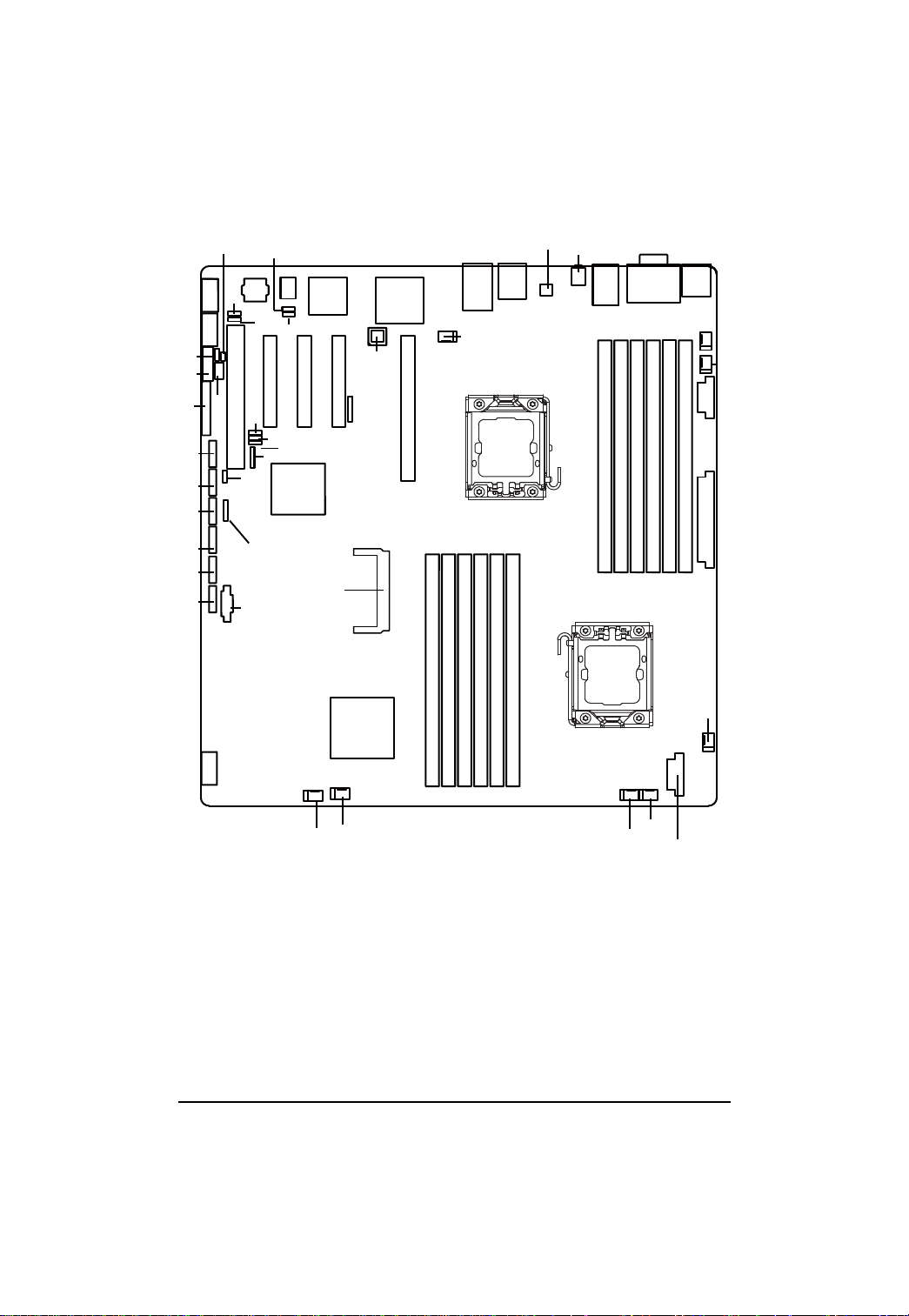
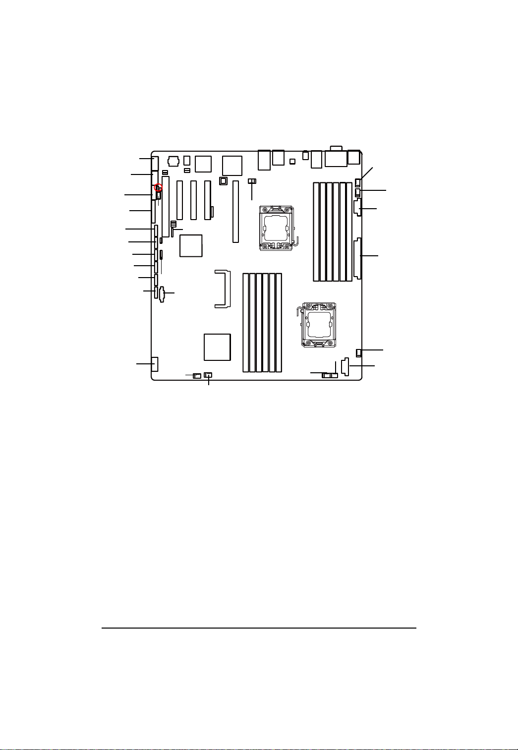
1.3. GA-7TESH2-RH Motherboard Component
No Code Description
1. CPU1 Primary CPU
2. CPU2 Secondary CPU
3. U82 Intel Tylersburg-36D IOH
4. U60 Intel ICH10R
5. U188 Winbond W83792G
6. U6 Intel 82576EB GbE
7. U24 Broadcom BCM5221PHY
8. U5 ServerEngines PilotII
9. U7 PilotII VGA memory
10. U9 BMC Flash ROM
11. COMB COM2 connector
12. BAT CMOS Battery
13. USB2 Rear USB connector
14. PCIE_SODIM SO-DIMM for SAS RAID card
15. USB1 Front USB connector
16. PSMI PSMI connector
17. IPMB2 IPMB2 connector
18. IPMB1 IPMB1 connector
19. CASEOPEN Case open intrusion
20. SATA0 SATA0 data cable connector
21. SATA1 SATA1 data cable connector
22. SATA2 SATA2 data cable connector
23. SATA3 SATA3 data cable connector
24. SATA4 SATA4 data cable connector
25. SATA5 SATA5 data cable connector
26. FAN_CPU1 CPU1 fan cable connector
27. FAN_CPU2 CPU2 fan cable connector
28. FAN_SYS1 System fan 1 cable connector
29. FAN_SYS2 System fan 2 cable connector
30. FAN_SYS3 System fan 3 cable connector
31. FAN_SYS4 System fan 4 cable connector
32. FAN_SYS5 System fan 5 cable connector
33. FAN_SYS6 System fan 6 cable connector
34. PCI5 PCI 32bit/33MHz slot
35. PCI-E4 PCI-E x8 slot (Gen1 at x4 bandwidth)
36. PCI-E3 PCI-E x8 slot (Gen2 at x4 bandwidth)
37. PCI-E2 PCI-E x8 slot (Gen2 at x8 bandwidth)
Introduction
8

GA-7TESH2-RH Motherboard
No Code Description
38. PCI-E1 PCI-E x16 slo t(Gen2 at x16 bandwidth)
39. DIMMC1 Channel C slot 1 (for primary CPU)
40. DIMMC2 Channel C slot 2 (for primary CPU)
English
41. DIMMB1 Channel B slot 1 (for primary CPU)
42. DIMMB2 Channel B slot 2 (for primary CPU)
43. DIMMA1 Channel A slot 1 (for primary CPU)
44. DIMMA2 Channel A slot 2 (for primary CPU)
45. DIMMD2 Channel D slot 2 (for secondary CPU)
46. DIMMD1 Channel D slot 1 (for secondary CPU)
47. DIMME2 Channel E slot 2 (for secondary CPU)
48. DIMME1 Channel E slot 1 (for secondary CPU)
49. DIMMF2 Channel F slot 2 (for secondary CPU)
50. DIMMF1 Channel F slot 1 (for secondary CPU)
51. KB_MS PS/2 Keyboard/Mouse ports
52. COMA_VGA Serial/VGA ports
53. USB USB ports
54. ID_SW ID Sw itch
55. MNGT_NIC 10/100 LAN port (for KVM server management)
56. GBE1_2 Gigabit LAN ports
57. F_Panel Front panel connector
58. ATX 24-pin Power connector
59. 12V_AUX2 CPU2 8-pin Power connector
60. 12V_AUX1 CPU1 8-pin Power connector
61. SGPIO_ JP1 SGPIO JP1 jumper
62. J3 SMBus connector for B/P board
63. CLR_CMOS Clear CMOS jumper
64. CLR_RTC Clear RTC jumper
65. BIOS_RVCR BIOS Recovery jumper
66. PASS_DIS Password Disable jumper
67. BMC_SEL BMC Select jumper
68 . JP_STRP2 Pi lo tII fir mwar e upgrade jumper
69 . JP_STRP8 Pi lo tII fir mwar e upgrade jumper
70. PILOT_DIS PiotII disable jumper
9
GA-7TESH2-RH Motherboard
English
17
12
57
25
24
23
22
21
20
11
13
19
18
10
68
67
34 35
64
63
61
16
62
70
65
69
66
7
54
55
9
8
37
36
4
14
6
5
38
3
56
27
2
4039 44434241
53 52
4546 4847 5049
1
51
32
33
59
58
26
15
31
30
10
29
28
60
Hardware Installation Process
Chapter 2 Hardware Installation Process
2.1. Installing Processor and CPU Haet Sink
Before installing the processor and cooling fan, adhere to the following
cautions:
1. The processor will overheat without the heatsink and/or fan, resulting in permanent
irreparable damage.
2. Never force the processor into the socket.
3. Apply thermal grease on the processor before placing cooling fan.
4. Please make sure the CPU type is supported by the motherboard.
5. If you do not match the CPU socket Pin 1 and CPU cut edge well, it will cause
improper installation. Please change the insert orientation.
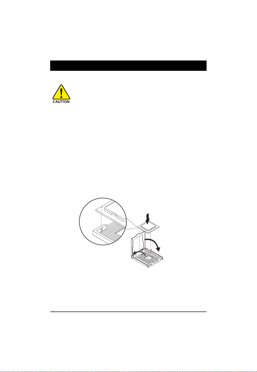
2.1.1. Installing CPU
Step 1 Raise the metal locking lever on the socket.
Step 2 Remove the plastic covering on the CPU socket.
Step 3 Insert the CPU with the correct orientation. The CPU only fits in one orientation.
Step 4 Once the CPU is properly placed, please replace the metal cover and push the metal
lever back into locked position.
11
GA-7TESH2-RH Motherboard
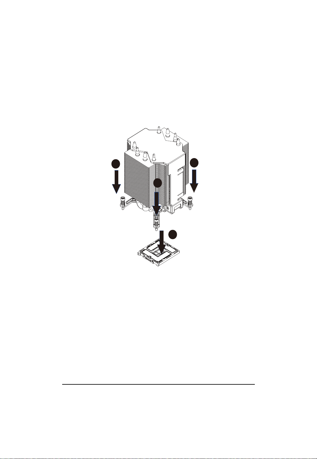
2.1.2. Installing Heat Sink
Step 1 Attach the heat sink clip to the processor socket.
Step 2 Secure the cooing fan withscrews.
English
Step 3 Connect processor fan can cable to the processor fanconnector
2
2
2
1
12
Hardware Installation Process
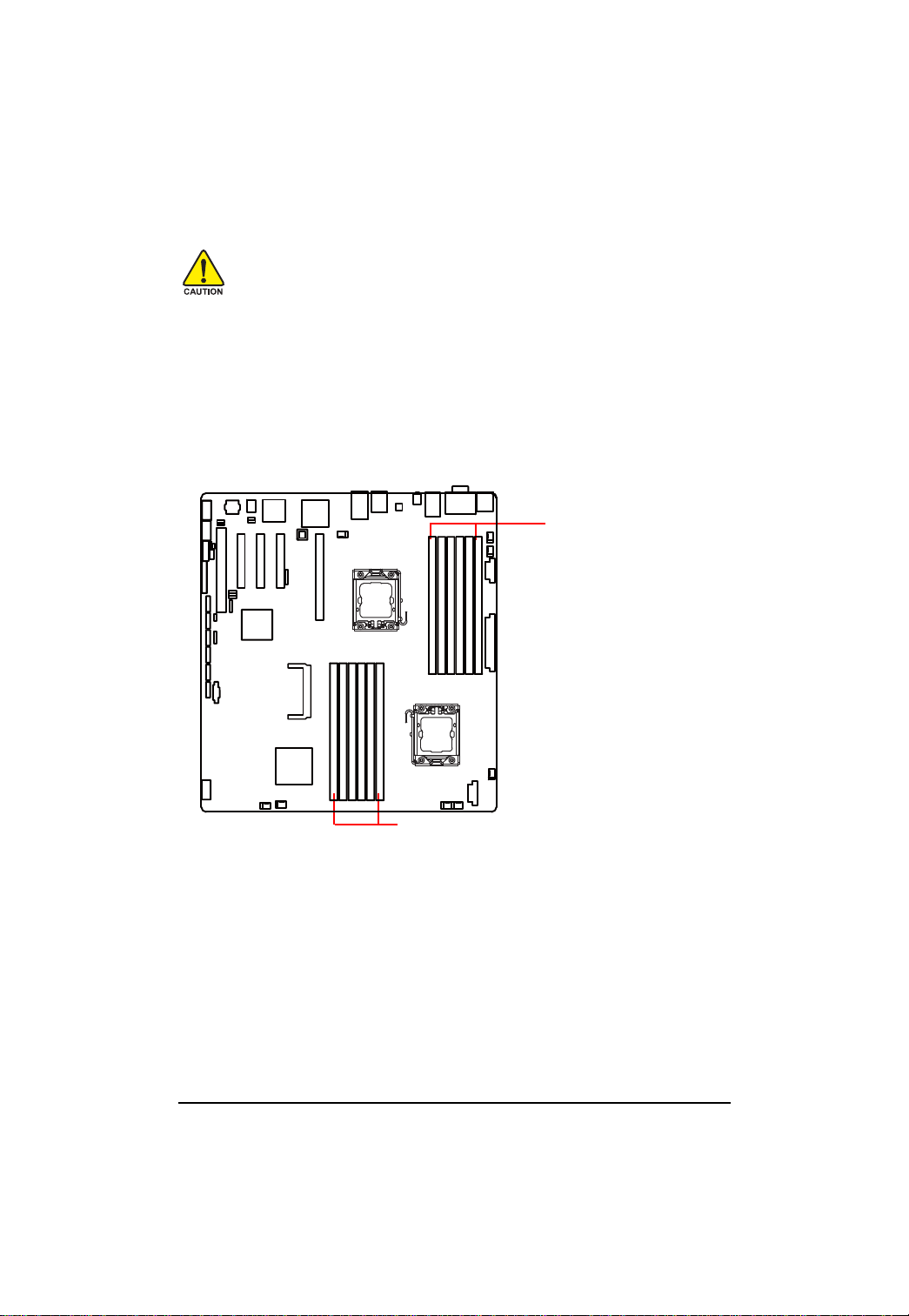
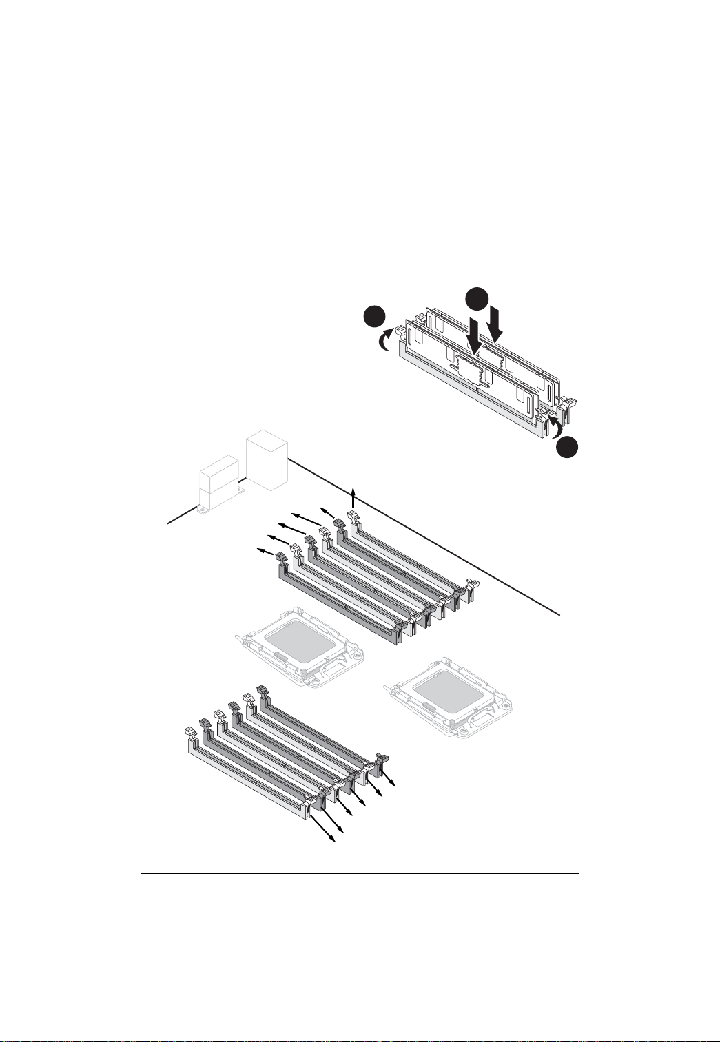
2.2. Installing memory modules
Before installing the memory modules, please comply with the following conditions:
1. Please make sure that the memory is supported by the motherboard. It is
recommended to use the memory with similar capacity, specifications and brand.
2. Before installing or removing memory modules, please make sure that the computer
power is switched off to prevent hardware damage.
3. Memory modules have a foolproof insertion design. A memory module can be installed
in only one direction. If you are unable to insert the module, please switch the direction.
The motherboard supports DDR3 memory modules, whereby BIOS will automatically detect memory
capacity and specifications. Memory modules are designed so that they can be inserted only in one
direction. The memory capacity used can differ with each slot.
Memory sockets for
Processor 2
Memory sockets for Processor 1
13
Hardware Installation Process
Installation Steps:
Step 1. Insert the DIMM memory module vertically into the DIMM slot, and push it down.
Step 2. Close the plastic clip at both edges of the DIMM slots to lock the DIMM module.
NOTE! DIMM must be populated in order starting from DIMMA1/D1 socket. For dual-channel
operation, DIMMs must be installed in matched pairs.
Step 3. Reverse the installation steps when you wish to remove the DIMM module.
1
2
2
DIMMF1
DIMME1
DIMME2
DIMMD1
DIMMD2
DIMMF2
CPU2
CPU1
DIMMA2
DIMMA1
DIMMB2
DIMMB1
DIMMC2
DIMMC1
14
GA-7TESH2-RH Motherboard
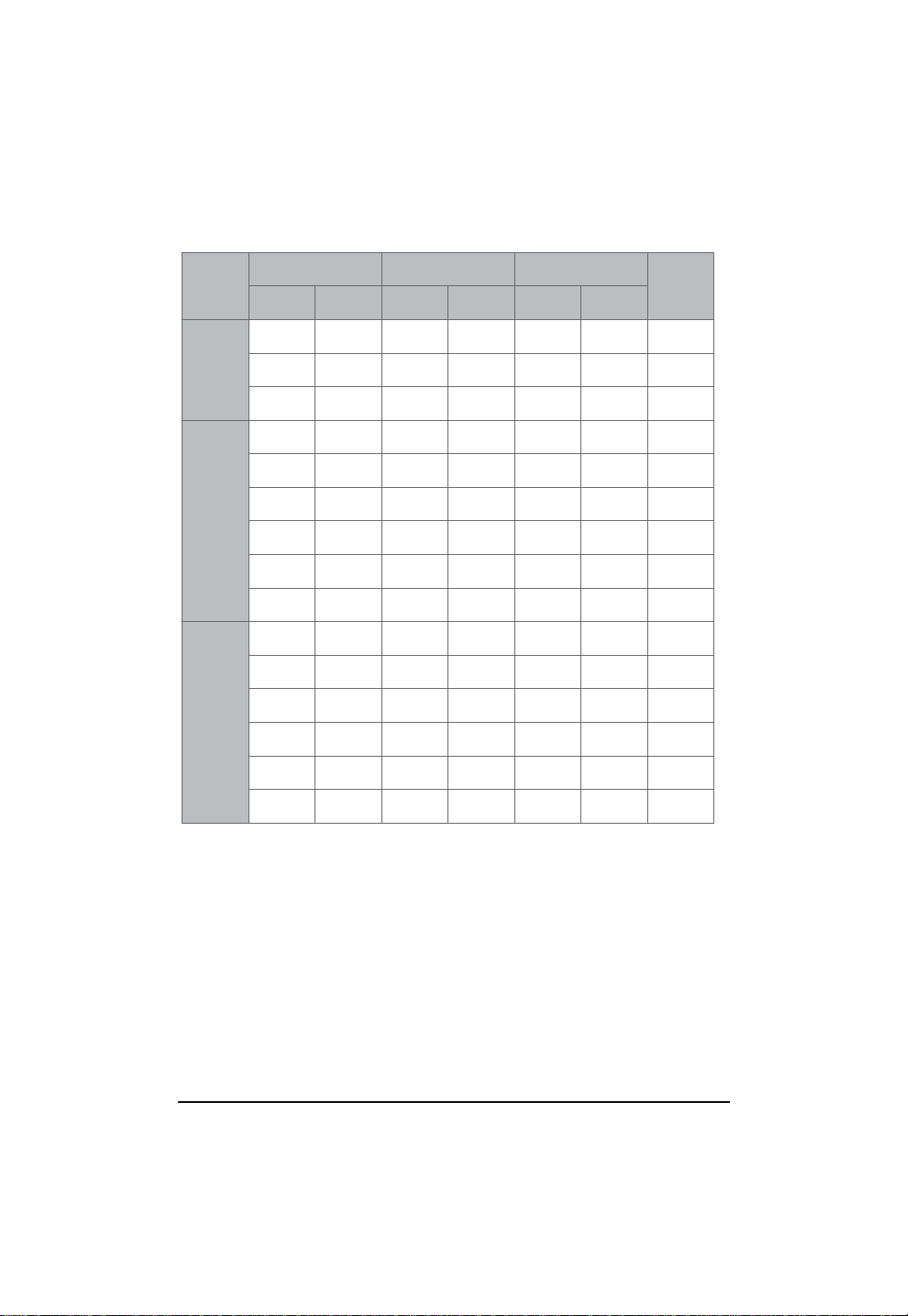
U-DIMM Population Table
Interleave
English
mode
Single
Channel
Dual
Channel
Three
Channel
Channel A Channel B Channel C
DIMMA1/D1
DIMMA2/D2 DIMMB1/E1 DIMMB2/E2 DIMMC1/F1 DIMMC2/F2
1GB
2GB
4GB
1GB
2GB
4GB
1GB
2GB
4GB
1GB
2GB
4GB
1GB
1GB
2GB
4GB
1GB
1GB
2GB
4GB
1GB
2GB
4GB
1GB
2GB
4GB
1GB
1GB
2GB
4GB
1GB
1GB
2GB
4GB
1GB
1GB
Total
Memory
1GB
2GB
4GB
2GB
4GB
8GB
4GB
8GB
16GB
3GB
6GB
16GB
6GB
2GB
4GB
2GB
4GB
2GB
4GB
15
2GB
4GB
2GB
4GB
2GB
4GB
12GB
24GB
GA-7TESH2-RH Motherboard
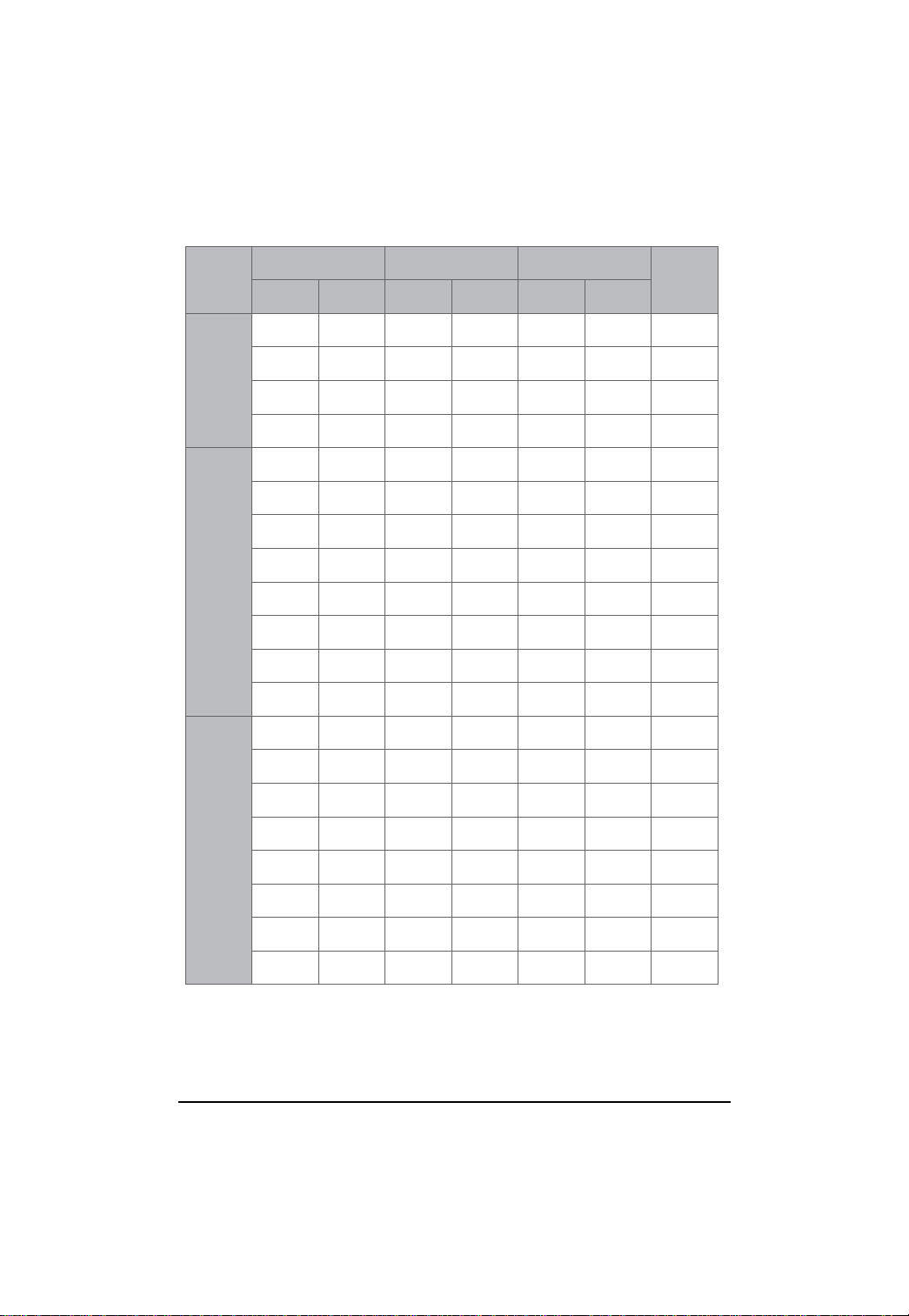
R-DIMM Population Table
English
Interleave
mode
Single
Channel
Dual
Channel
Channel A Channel B Channel C
DIMMA1/D1
DIMMA2/D2 DIMMB1/E1 DIMMB2/E2 DIMMC1/F1 DIMMC2/F2
1GB
2GB
4GB
8GB
1GB
2GB
4GB
8GB
1GB
2GB
4GB
8GB
1GB
1GB 1GB
2GB
4GB
8GB
1GB
2GB
4GB
8GB
2GB
4GB
8GB
1GB
1GB
2GB
4GB
8GB
1GB
Total
Memory
1GB
2GB
4GB
8GB
2GB
4GB
8GB
16GB
4GB
8GB
16GB
32GB
3GB
Three
Channel
2GB
4GB
8GB
1GB
2GB
4GB
8GB
1GB
2GB
4GB
8GB
2GB
4GB
8GB
1GB
2GB
4GB
8GB
16
1GB
2GB
4GB
8GB
2GB
4GB
8GB
1GB
2GB
4GB
8GB
1GB
2GB
4GB
8GB
6GB
12GB
24GB
6GB
12GB
24GB
48GB
Hardware Installation Process
2.3. Connect ribbon cables, cabinet wires, and power supply
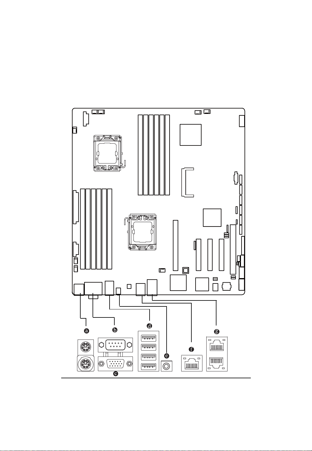
2.3.1. I/O Back Panel Introduction
17

GA-7TESH2-RH Motherboard
English
PS/2 Keyboard and PS/2 Mouse Connector
To install a PS/2 port keyboard and mouse, plug the mouse to the upper port (green) and the
keyboard to the lower port (purple).
Serial Port
Connects to serial-based mouse or data processing devices.
Video Port
The video in port allows connect to video in, which can also apply to video loop thru function.
USB Port
Before you connect your device(s) into USB connector(s), please make sure your device(s)
such as USB keyboard, mouse, scanner, zip, speaker...etc. have a standard USB interface.
Also make sure your OS supports USB controller. If your OS does not support USB controller,
please contact OS vendor for possible patch or driver updated. For more information please
contact your OS or device(s) vendors.
ID Switch
This button provide the selected unit idenfication function.
KVM Server Management 10/100 LAN Port
The LAN port provides Internet connection with data transfer speeds of 10/100Mbps.
Gigabit LAN Ports
The LAN port provides Internet connection of Gigabit Ethernet with data transfer speeds of
10/100/1000Mbps.
18
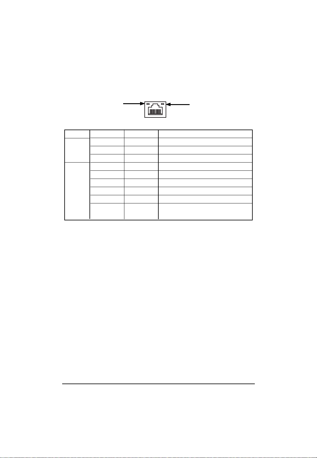
LAN LED Description
Hardware Installation Process
LED2 (Green/Yellow)
Name
LED1
Color Condition Description
Green ON LAN Link / no Access
Green BLINK LAN Access
- OFF Idle
LED2
- OFF 10Mbps connection
Green BLINK Port identification with 10 Mbps connection
Green ON 100Mbps connection
Green BLINK Port identification with 100Mbps connection
Yellow ON 1Gbps connection
Yellow BLINK Port identification with 1Gbps connection
LED1 (Green)
19
GA-7TESH2-RH Motherboard
2.4. Connectors Introduction
English
1. ATX 18. SYS_FAN1 (System fan connector)
2. 12V_AUX1 19. SYS_FAN2 (System fan connector))
3. 12V_AUX2 20. SYS_FAN3 (System fan connector)
4. COMB 21. SYS_FAN4 (System fan connector)
5. USB1 (Front USB cable connector) 22. SYS_FAN5 (System fan connector)
6. USB2 (Rear USB cable connector) 23. SYS_FAN6 (System fan connector)
7. F_PANEL 24. IPMB1
8. SATA0 (SATA data cable connector) 25. IPMB2
9. SAT A1 (SATA data cable connector) 26. SGPIO_JP1
10. SATA2 (SATA data cable connector) 27. J3 SMBus
11. SATA3 (SATA data cable connector)
12. SATA4 (SATA data cable connector)
13. SATA5 (SATA data cable connector
14. PSMI
15. CMOS Battery
16. CPU_F AN1 (CPU1 fan cable connector)
17. CPU_F AN2 (CPU1 fan cable connector)
15
13
12
4
22
6
25
7
24
17
23
3
27
11
1
10
9
26
8
5
14
21
19
18
16
2
20
20
GA-7TESH2-RH Motherboard
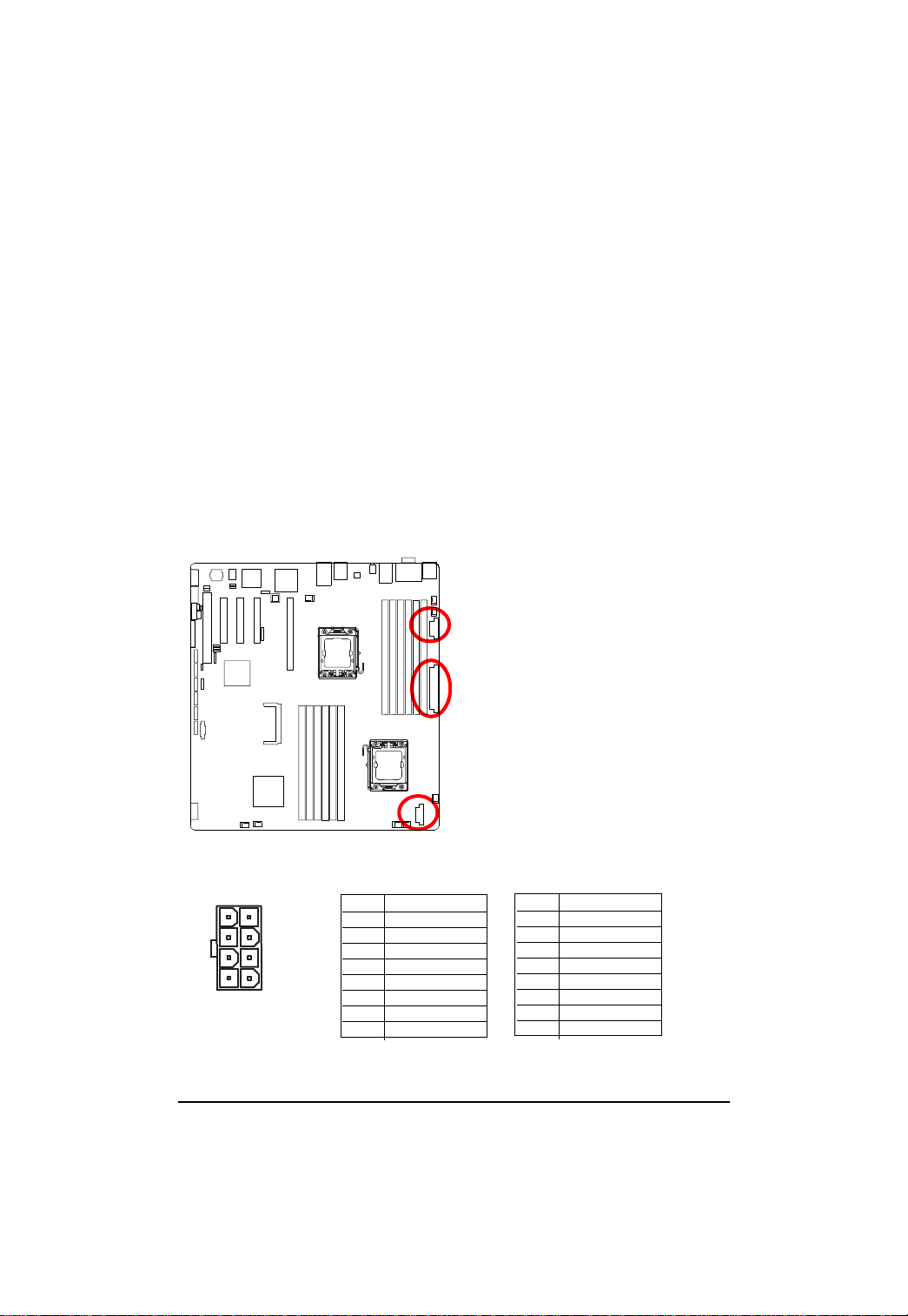
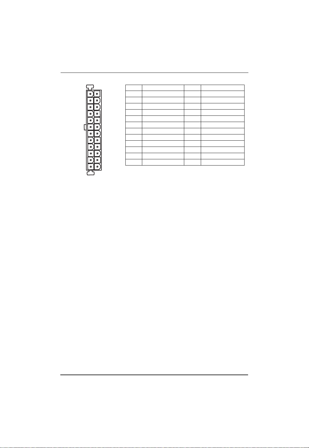
1/2/3 ) ATX/12V_AUX1/12V_AUX2 (24-pin/8-pin ATX power connectors)
English
With the use of the power connector, the power supply can supply enough stable power to all the
components on the motherboard. Before connecting the power connector, please make sure that
all components and devices are properly installed. Align the power connector with its proper
location on the motherboard and connect tightly.
The ATX_12V power connector mainly supplies power to the CPU. If the ATX_12V
power connector is not connected, the system will not start.
Caution! Please use a power supply that is able to support the system voltage
requirements. It is recommended that a power supply that can withstand high power
consumption be used (350W or greater). If a power supply is used that does not provide
the required power, the result can lead to an unstable system or a system that is unable
to start. If you use a power supply that provides a 24-pin A TX power connector, please
remove the small cover on the power connector on the motherboard before plugging in
the power cord; otherwise, please do not remove it.
5481
CPU0/DDR3 socket for CPU0
Pin No. Definition
1 GND
2 GND
3 GND
4 GND
5 P12V_DDR3_CPU0
6 P12V_DDR3_CPU0
7 P12V_CPU0
8 P12V_CPU0
21
CPU1/DDR3 socket for CPU1
Pin No. Definition
1 GND
2 GND
3 GND
4 GND
5 P12V_DDR3_CPU1
6 P12V_DDR3_CPU1
7 P12V_CPU1
8 P12V_CPU1
Connector Introduction
13
1
Pin No. Definition
1 3.3V
2 3.3V
3 GND
4 +5V
5 GND
6 +5V
7 GND
8 Power Good
9 5V SB(stand by +5V)
10 +12V
1 1 +12V(Only for 24-pin ATX)
12 3.3V(Only for 24-pin ATX)
12
24
Pin No. Definition
13 3.3V
14 -12V
15 GND
16 PS_ON(soft On/Off)
17 GND
18 GND
19 GND
20 -5V
21 +5V
22 +5V
23 +5V (Only for 24-pin A TX)
24 GND(Only for 24-pin A TX)
22
GA-7TESH2-RH Motherboard
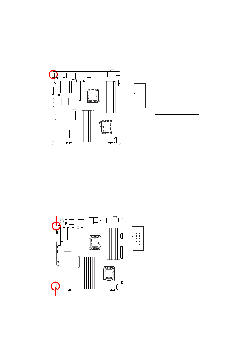
4 ) COMB
English
5/6 ) USB1/2 (USB cable connectors)
2
1
10 9
Pin No. Definition
1 DCD2 SIN2
3 SOUT2
4 DTR25 GND
6 DSR27 RTS28 CTS29 RI210 NC
Be careful with the polarity of the front USB connector. Check the pin assignment carefully while
you connect the front USB cable, incorrect connection between the cable and connector will make
the device unable to work or even damage it. For optional front USB cable, please contact your
local dealer.
USB2
12
910
Pin No. Definition
1 5V power
2 5V power
3 -FUSB4
4 -FUSB5
5 +FUSB4
6 +FUSB5
7 GND
8 GND
9NC
10 NC
USB1
23
 Loading...