

Page 1

GA-7PCSL
GA-7PCSLX
LGA1356 socket motherboard for Intel® Xeon® series processors
User's Manual
Rev. 1001
Page 2

Copyright
© 2012 GIGA-BYTE TECHNOLOGY CO., LTD. All rights reserved.
The trademarks mentioned in this manual are legally registered to their respective owners.
Disclaimer
Information in this manual is protected by copyright laws and is the property of GIGABYTE.
Changes to the specifications and features in this manual may be made by GIGABYTE
without prior notice. No part of this manual may be reproduced, copied, translated, transmitted, or
published in any form or by any means without GIGABYTE's prior written permission.
Documentation Classications
In order to assist in the use of this product, GIGABYTE provides the following types of documentations:
For quick set-up of the product, read the Quick Installation Guide included with the product.
For detailed product information, carefully read the User's Manual.
For product-related information, check on our website at:
http://www.gigabyte.com
Page 3

Table of Contents
Box Contents ...................................................................................................................5
GA-7PCSL Motherboard Layout ......................................................................................6
GA-7PCSLX Motherboard Layout ...................................................................................9
Chapter 1 Hardware Installation ...................................................................................12
1-1 Installation Precautions .................................................................................. 12
1-2 ProductSpecications .................................................................................... 13
1-3 Installing the CPU and CPU Cooler ............................................................... 17
1-3-1 Installing the CPU ...................................................................................................17
1-3-2 Installing the CPU Cooler .......................................................................................18
1-4 Installing the Memory ..................................................................................... 19
1-4-1 Dual/3ChannelMemoryConguration ..................................................................19
1-4-2 Installing a Memory ...............................................................................................20
1-5 Back Panel Connectors .................................................................................. 21
1-6 Internal Connectors ........................................................................................ 22
1-7 Jumper Setting ............................................................................................... 44
Chapter 2 BIOS Setup ..................................................................................................54
2-1 The Main Menu .............................................................................................. 56
2-2 Advanced Menu ............................................................................................. 58
2-2-1 PCIConguration ...................................................................................................59
2-2-2 Trusted Computing (Optioanl) ................................................................................60
2-2-3 CPUConguration ..................................................................................................61
2-2-3-1 CPUPowerManagementConguration ................................................................64
2-2-4 Runtime Error Logging ...........................................................................................66
2-2-5 SATAConguration.................................................................................................67
2-2-6 SASConguration ..................................................................................................68
2-2-7 SuperIOConguration ...........................................................................................69
2-2-8 Serial Port Console Redirection ............................................................................71
2-3 Chipset Menu ................................................................................................. 74
2-3-1 NorthBridgeConguration .....................................................................................75
2-3-1-1 IOHConguration ...................................................................................................77
2-3-1-2 DIMM Information ...................................................................................................79
2-3-2 SouthBridgeConguration ....................................................................................80
2-4 Security Menu ................................................................................................ 82
2-5 Server Management Menu ............................................................................. 83
2-5-1 System Information .................................................................................................84
2-5-2 BMCLANConguration .........................................................................................85
- 3 -
Page 4

2-5-3 System Event Log ..................................................................................................86
2-6 Boot Option Menu .......................................................................................... 87
2-7 Boot Manager ................................................................................................. 88
2-8 Exit Menu ....................................................................................................... 89
Chapter 3 Appendix ......................................................................................................91
3-1 FAQ ................................................................................................................ 91
- 4 -
Page 5
Box Contents
GA-7PCSL/GA-7PCSLX motherboard
Driver CD
Two SATA cables
I/O Shield
• The box contents above are for reference only and the actual items shall depend on the product package you obtain.
The box contents are subject to change without notice.
• The motherboard image is for reference only.
- 5 -
Page 6
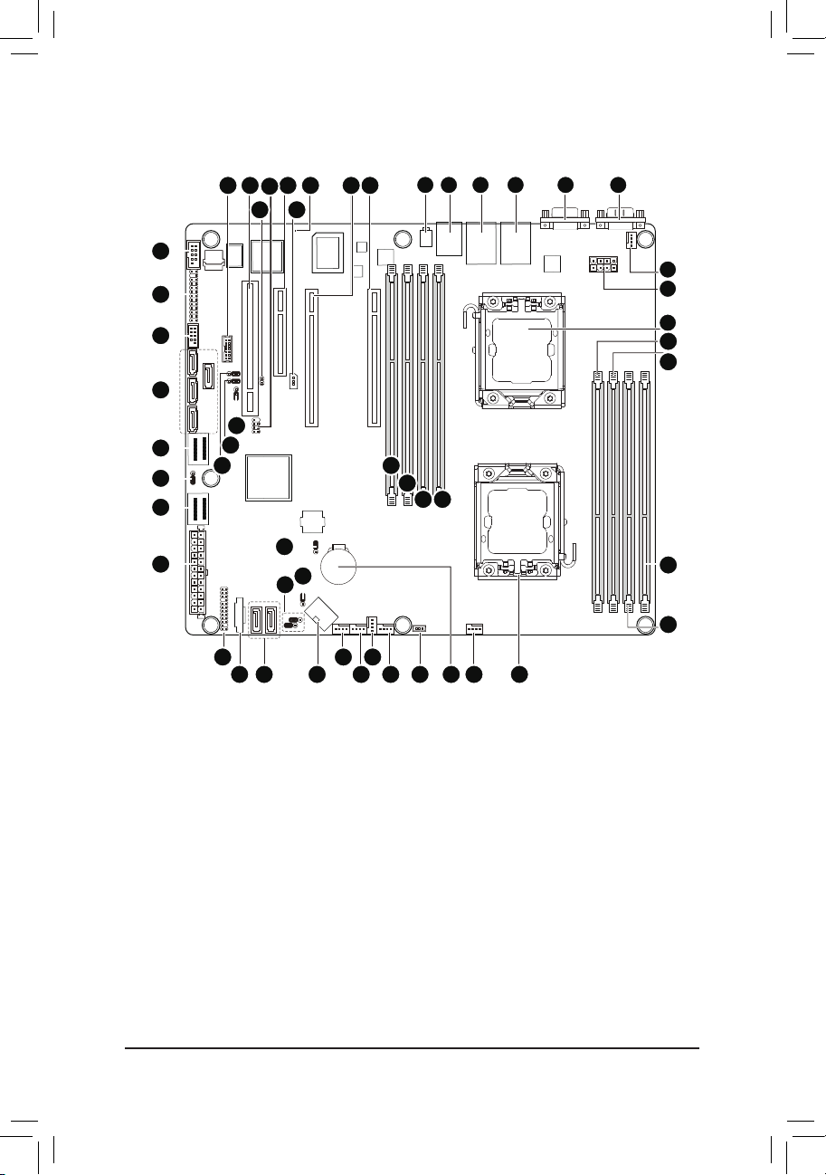
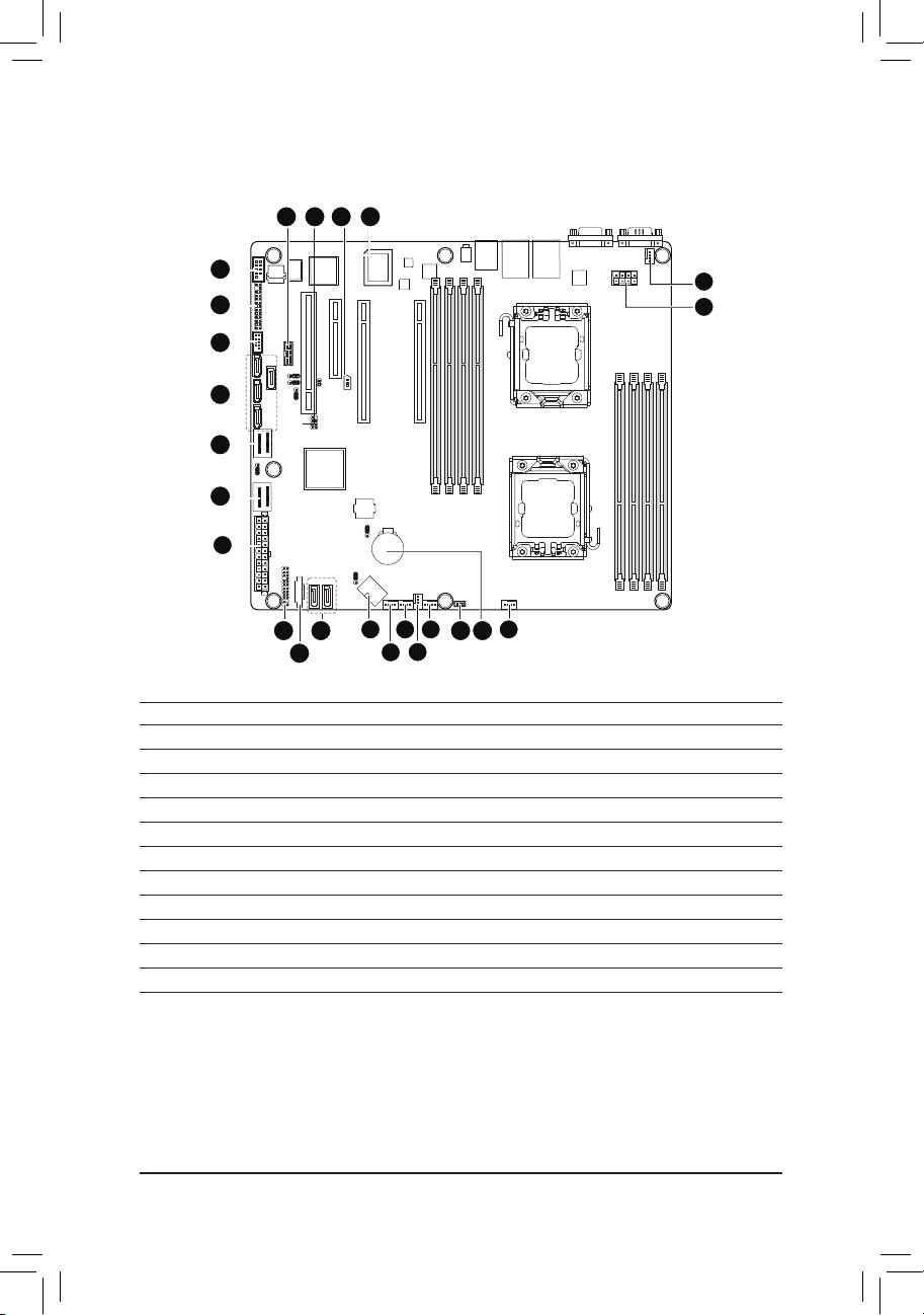
GA-7PCSL Motherboard Layout
33
32
31
30
29
28
27
26
34 35 38
37
36
49
48
47
25
50
52
39
51
40
42
41
1 2 3 4 6
5
7
8
9
10
11
43
44
45 46
12
13
19
21
20
222324
1415161718
- 6 -
Page 7

Item Code Description
1 ID_SW ID switch
2 MLAN BMC Management LAN port
3 USB_LANB1 LAN1 port (top) / USB ports (bottom)
4 USB_LANB2 LAN2 port (top) / USB ports (bottom)
5 VGA_1 VGA port
6 COM1 Serial port
7 CPU1_FAN CPU1 fan cable connector
8 P12V_AUX2 8 pin power connector
9 CPU1 Intel LGA1356 socket (Secondary CPU)
10 DDR3_P0_C1 Channel C slot 1 (for primary CPU)
11 DDR3_P0_C0 Channel C slot 0 (for primary CPU)
12 DDR3_P0_A0 Channel A slot 0 (for primary CPU)
13 DDR3_P0_B0 Channel B slot 0 (for primary CPU)
14 CPU0 Intel LGA1356 socket (Primary CPU)
15 CPU0_FAN CPU0 fan connector
16 BAT CMOS battery
17 SKU_KEY1 PBG A SKU Select connector
18 SYS_FAN4 System fan connector
19 SYS_FAN3 System fan connector
20 SYS_FAN2 System fan connector
21 SYS_FAN1 System fan connector
22 P12V_AUX1 8 pin power connector
23 SATA0/1 SATA 6Gb/s connectors
24 PMbus_CN_1 PM Bus connector
25 BP_1 HDD back plane connector
26 ATX1 24-pin power connector
27 MINISAS_2 Mini SAS connector (SATA 3.0Gb/s signal)
28 SSB_ME2 ME enable/disable jumper
29 MINISAS_1 Mini SAS connector
30 SAS0~3 SAS connectors
31 F_USB1 Front USB connector
32 FP_1 Front panel connector
33 COM2 Serial cable connector
34 TPM_MEZZ1 TPM connector
35 PCI_1 PCI slot (32bit/33MHz)
36 JP5 Chassis intrusion jumper
37 SCU_SGPIO SCU SGPIO connector
38 PCIE_3 PCI-E slot 3 (x8 slot / x4 signal)
39 IPMB IPMB connector
40 BMC_LED1 BMC Firmware Readiness LED
41 PCIE_2 PCI-E slot 2 (x16 slot / x8 signal)
42 PCIE_1 PCI-E slot 1 (x16 slot)
43 DDR3_P1_D0 Channel A slot 0 (for secondary CPU)
44 DDR3_P1_E0 Channel B slot 0 (for secondary CPU)
45 DDR3_P1_F0 Channel C slot 0 (for secondary CPU)
- 7 -
Page 8

46 DDR3_P1_F1 Channel C slot 1 (for secondary CPU)
47 PASSWORD Clear password jumper
48 BIOS_RVCR BIOS recovery jumper
49 SSB_ME1 ME enable/disable jumper
50 CLR_CMOS Clear CMOS jumper
51 BIOS_WP BIOS write protect jumper
52 SATA_DOM0/SATA_DOM1 SATA0/1 port DOM support jumper
- 8 -
Page 9
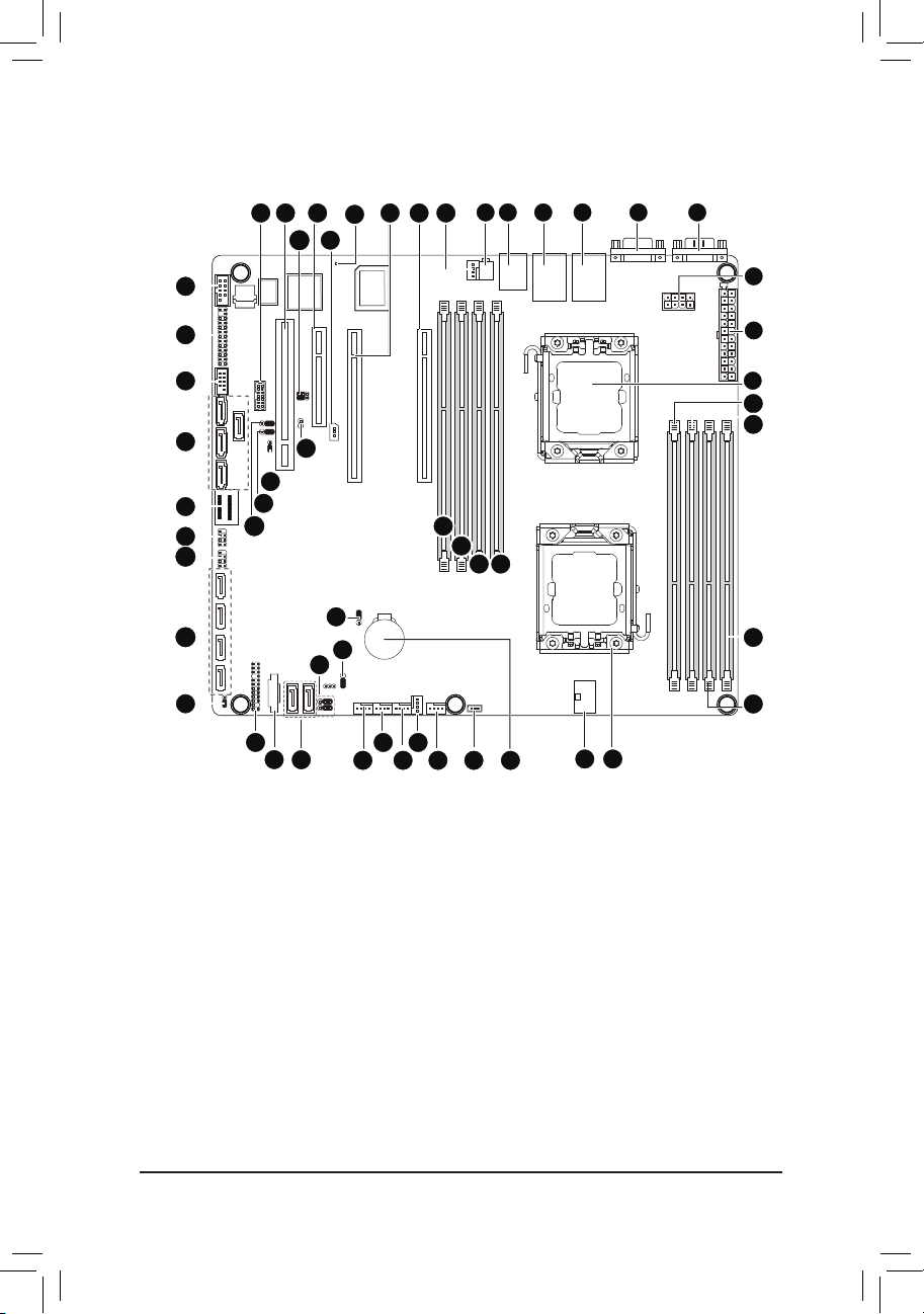
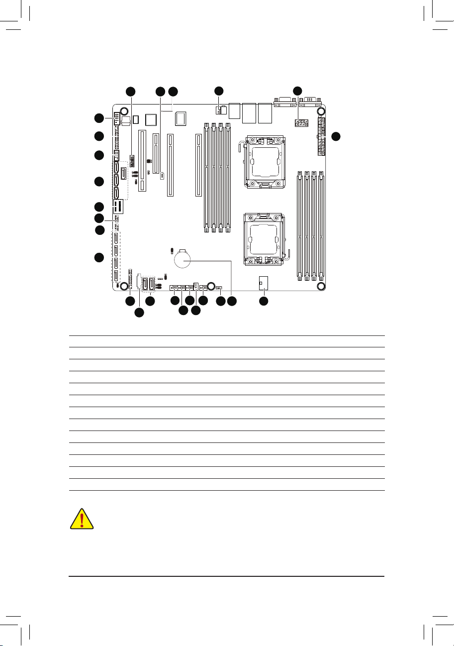
GA-7PCSLX Motherboard Layout
34
33
32
31
30
29
28
27
26
35 36
50
49
48
25
24
37
23
51
38
54
39
52
53
40
22
21
41
20
19
42
43
1 2 3 4 6
44
45
46 47
161718
5
7
8
9
10
11
12
13
1415
- 9 -
Page 10

Item Code Description
1 ID_SW ID switch
2 MLAN BMC Management LAN port
3 USB_LANB1 LAN1 port (top) / USB ports (bottom)
4 USB_LANB2 LAN2 port (top) / USB ports (bottom)
5 VGA_1 VGA port
6 COM1 Serial port
7 P12V_AUX2 8 pin power connector
8 ATX1 24-pin power connector
9 CPU1 Intel LGA1356 socket (Secondary CPU)
10 DDR3_P0_C1 Channel C slot 1 (for primary CPU)
11 DDR3_P0_C0 Channel C slot 0 (for primary CPU)
12 DDR3_P0_A0 Channel A slot 0 (for primary CPU)
13 DDR3_P0_B0 Channel B slot 0 (for primary CPU)
14 CPU0 Intel LGA1356 socket (Primary CPU)
15 P12V_AUX1 8 pin power connector
16 BAT CMOS battery
17 SKU_KEY1 PBG A SKU Select connector
18 CPU0_FAN CPU0 fan connector
19 SYS_FAN4 System fan connector
20 SYS_FAN3 System fan connector
21 SYS_FAN2 System fan connector
22 SYS_FAN1 System fan connector
23 SATA0/1 SATA 6Gb/s connectors
24 PMbus_CN_1 PM Bus connector
25 BP_1 HDD back plane connector
26 SSB_ME2 ME enable/disable jumper
27 SATA2/3/4/5 SATA 3Gb/s connectors
28 SATA_SGPIO SATA SGPIO coneector
29 SCU_SGPIO SCU SGPIO connector
30 MINISAS_1 Mini SAS connector
31 SAS0~3 SAS connectors
32 F_USB1 Front USB connector
33 FP_1 Front panel connector
34 COM2 Serial cable connector
35 TPM_MEZZ1 TPM connector
36 PCI_1 PCI slot (32bit/33MHz)
37 ROMST_FRB3 Force to Stop FRB3 Timer jumper
38 PCIE_3 PCI-E slot 3 (x8 slot / x4 signal)
39 IPMB IPMB connector
40 BMC_LED1 BMC Firmware Readiness LED
41 PCIE_2 PCI-E slot 2 (x16 slot / x8 signal)
42 PCIE_1 PCI-E slot 1 (x16 slot)
43 CPU1_FAN CPU1 fan connector
44 DDR3_P1_D0 Channel A slot 0 (for secondary CPU)
45 DDR3_P1_E0 Channel B slot 0 (for secondary CPU)
- 10 -
Page 11
46 DDR3_P1_F0 Channel C slot 0 (for secondary CPU)
47 DDR3_P1_F1 Channel C slot 1 (for secondary CPU)
48 PASSWORD Clear password jumper
49 BIOS_RCVR BIOS recovery jumper
50 SSB_ME1 ME enable/disable jumper
51 JP5 Chassis intrusion jumper
52 CLR_CMOS Clear CMOS jumper
53 BIOS_WP BIOS write protect jumper
54 SATA_DOM0/SATA_DOM1 SATA0/1 port DOM support jumper
CAUTION! If a SATA type hard drive is connected to the motherboard, please ensure the jumper is
closed and set to 2-3 pins (Normal mode), in order to reduce any risk of hard disk damage. Please
refer to Page 49 for SATA_DOM0 and SATA_DOM1 jumper setting instruction.
- 11 -
Page 12

Hardware Installation
Chapter 1 Hardware Installation
1-1 Installation Precautions
The motherboard contains numerous delicate electronic circuits and components which can
become damaged as a result of electrostatic discharge (ESD). Prior to installation, carefully read
the user's manual and follow these procedures:
• Prior to installation, do not remove or break motherboard S/N (Serial Number) sticker or
warranty sticker provided by your dealer. These stickers are required for warranty validation.
• Always remove the AC power by unplugging the power cord from the power outlet before
installing or removing the motherboard or other hardware components.
• When connecting hardware components to the internal connectors on the motherboard,
make sure they are connected tightly and securely.
• When handling the motherboard, avoid touching any metal leads or connectors.
• It is best to wear an electrostatic discharge (ESD) wrist strap when handling electronic com-
ponents such as a motherboard, CPU or memory. If you do not have an ESD wrist strap,
keep your hands dry and rst touch a metal object to eliminate static electricity.
• Prior to installing the motherboard, please have it on top of an antistatic pad or within an
electrostatic shielding container.
• Before unplugging the power supply cable from the motherboard, make sure the power sup-
ply has been turned off.
• Before turning on the power, make sure the power supply voltage has been set according to
the local voltage standard.
• Before using the product, please verify that all cables and power connectors of your hard-
ware components are connected.
• To prevent damage to the motherboard, do not allow screws to come in contact with the
motherboard circuit or its components.
• Make sure there are no leftover screws or metal components placed on the motherboard or
within the computer casing.
• Do not place the computer system on an uneven surface
• Do not place the computer system in a high-temperature environment.
• Turning on the computer power during the installation process can lead to damage to sys-
tem components as well as physical harm to the user.
• If you are uncertain about any installation steps or have a problem related to the use of the
product, please consult a certied computer technician.
.
- 12 -
Page 13
Hardware Installation
1-2 ProductSpecications
GA-7PCSL
CPU Support for Dual Intel® Xeon® Sandy-bridge-EN 2S processors in 1356 socket
Intel® Xeon® Quad Core in LGA 1356 socket
Supports QuickPath Interconnect up to 8GT/s
Enhanced Intel SpeedStep Technology (EIST) & Demand BasedSwitch (DBS)
Enhanced Intel SpeedStep Technology (EIST)
Support Intel Virtualization Technology (VT)
Chipset Intel® C600 (Patsburg) Chipset
Memory 8 x 1.5V DDR3 DIMM sockets supporting up to 64 GB of systemmemory
LAN 2 x Intel® 82574L supports 10/100/1000 Mbps
Expansion Slots 1 x PCI Express x16 slot, running at x16 (PCIE_1)
Onboard
Graphics
Storage Interface Intel® C600 controller
USB Up to 6 US B 2.0/1.1 ports (4 on the bac k panel, 2 via the USB bra ckets connected
* Due to Windows 32-bit operating system limitation, when more than 4 GB of physical
memory is installed, the actual memory size displayed will be less than 4 GB.
8 x 1.35V DDR3L DIMM sockets supporting up to 32 GB of system memory
3 channel memory architecture
Support for 800/1066/1333/1600 memory modules
Support for ECC RDIMM/ UDIMM memory modules
1 x PCI Express x8 slot, running at x8 (PCIE_2)
1 x PCI Express x8 slot, running at x4 (PCIE_ 3)
1 x PCI slot 32-Bit/33MHz (PCI_1)
ASPEED® AST2300 supports 16MB VR AM
4 x SATA 3Gb/s connectors (SAS0/1/2/3/via SCU)
1 x mini SAS connectors (4 SATA ports (3Gb/s)/optional with Upgrade ROM
attached)
1 x mini SAS connector (4 SATA ports (3Gb/s)
2 x SATA 6Gb/s connectors (SATA0/1)
Support for Intel RSTe SATA RAID 0, R AID 1
to the internal USB headers)
- 13 -
Page 14
Hardware Installation
Internal
Connectors
1 x 24-pin ATX main power connector
2 x 8-pin ATX 12V power connector
4 x SATA 3Gb/s connectors (SAS0~3)
2 x mini SAS 3Gb/s connectors
2 x SATA 6Gb/s connectors
1 x PSMI header
2 x CPU fan header
4 x System fan header
1 x Front panel header
2 x USB 2.0/1.1 headers
1 x Serial port header
1 x SPGIO header
Rear Panel I/O 4 x USB 2.0/1.1 ports
2 x RJ-45 port
1 x COM port
1 x VGA port
1 x ID Switch button
I/O Controller ASPEED® AST2300 BMC chip
Hardware
Monitor
System voltage detection
CPU/System temperature detection
CPU/System fan speed detection
CPU/System fan speed control
* Whether the CPU/system fan speed control function is supported will depend on
the CPU/system cooler you install.
BIOS 1 x 64 Mbit ash
AMI BIOS
Form Factor CEB Form Factor; 12 inch x 10.5 inch, 6 layers PCB
* GIGA BYTE reserves the right to make any changes to the product specications and product-related information
without prior notice.
- 14 -
Page 15
Hardware Installation
GA-7PCSLX
CPU Support for Dual Intel® Xeon® Sandy-bridge-EN 2S processors in 1356 socket
Intel® Xeon® Quad Core in LGA 1356 socket
Suppor ts QuickPath Interconnect up to 8GT/s
Enhanced Intel SpeedStep Technology (EIST) & Demand BasedSwitch (DBS)
Enhanced Intel SpeedStep Technology (EIST)
Support Intel Virtualization Technology (VT)
Chipset Intel® C600 (Patsburg) Chipset
Memory 8 x 1.5V DDR3 DIMM sockets supporting up to 64 GB of systemmemory
LAN 2 x Intel® 82574L supports 10/100/1000 Mbps
Expansion Slots 1 x PCI Express x16 slot, running at x16 (PCIE_1)
Onboard
Graphics
Storage Interface Intel® C600 controller
USB Up to 6 US B 2.0/1.1 p orts (4 on the back panel, 2 v ia the USB brackets co nnected
* Due to Windows 32-bit operating system limitation, when more than 4 GB of physical
memory is installed, the actual memory size displayed will be less than 4 GB.
8 x 1.35V DDR3L DIMM sockets supporting up to 32 GB of system memory
3 channel memory architecture
Support for 800/1066/1333/1600 memory modules
Support for ECC RDIMM/ UDIMM memory modules
1 x PCI Express x8 slot, running at x8 (PCIE_2)
1 x PCI Express x8 slot, running at x4 (PCIE_3)
1 x PCI slot 32-Bit/33MHz (PCI_1)
ASPEED® AST2300 supports 16MB VR AM
4 x SATA 3Gb/s connectors (SAS0/1/2/3/via SCU)
1 x mini SAS connector (4 SATA ports (3Gb/s)/optional with Upgrade ROM
attached)
4 x SATA 3Gb/s connectors (SATA2/3/4/5)
2 x SATA 6Gb/s connectors (SATA0/1)
Support for Intel RSTe SATA RAID 0, R AID 1
to the internal USB headers)
- 15 -
Page 16
Hardware Installation
Internal
Connectors
1 x 24-pin ATX main power connector
2 x 8-pin ATX 12V power connector
4 x SATA 3Gb/s connectors (SAS0/1/2/3)
1 x mini SAS 3Gb/s connector
4 x SATA 3Gb/s connectors (SATA2/3/4/5)
2 x SATA 6Gb/s connectors
1 x PSMI header
2 x CPU fan header
4 x System fan header
1 x Front panel header
2 x USB 2.0/1.1 headers
1 x Serial port header
1 x SPGIO header
Rear Panel I/O 4 x USB 2.0/1.1 ports
2 x RJ-45 port
1 x COM port
1 x VGA port
1 x ID Switch button
I/O Controller ASPEED® AST2300 BMC chip
Hardware
Monitor
System voltage detection
CPU/System temperature detection
CPU/System fan speed detection
CPU/System fan speed control
* Whether the CPU/system fan speed control function is supported will depend on
the CPU/system cooler you install.
BIOS 1 x 64 Mbit ash
AMI BIOS
Form Factor CEB Form Factor; 12 inch x 10.5 inch, 8 layers PCB
* GIGA BYTE reserves the right to make any changes to the product specications and product-related information
without prior notice.
- 16 -
Page 17
Hardware Installation
1-3 Installing the CPU and CPU Cooler
Read the following guidelines before you begin to install the CPU:
• Make sure that the motherboard supports the CPU.
(Go to GIGABYTE's website for the latest CPU support list.)
• Always turn off the computer and unplug the power cord from the power outlet before installing
the CPU to prevent hardware damage.
• Locate the pin one of the CPU. The CPU cannot be inserted if oriented incorrectly. (Or you may
locate the notches on both sides of the CPU and alignment keys on the CPU socket.)
• Apply an even and thin layer of thermal grease on the surface of the CPU.
• Do not turn on the computer if the CPU cooler is not installed, otherwise overheating and
damage of the CPU may occur.
• Set the CPU host frequency in accordance with the CPU specications. It is not recommended
that the system bus frequency be set beyond hardware specications since it does not meet the
standard requirements for the peripherals. If you wish to set the frequency beyond the standard
specifications, please do so according to your hardware specifications including the CPU,
graphics card, memory, hard drive, etc.
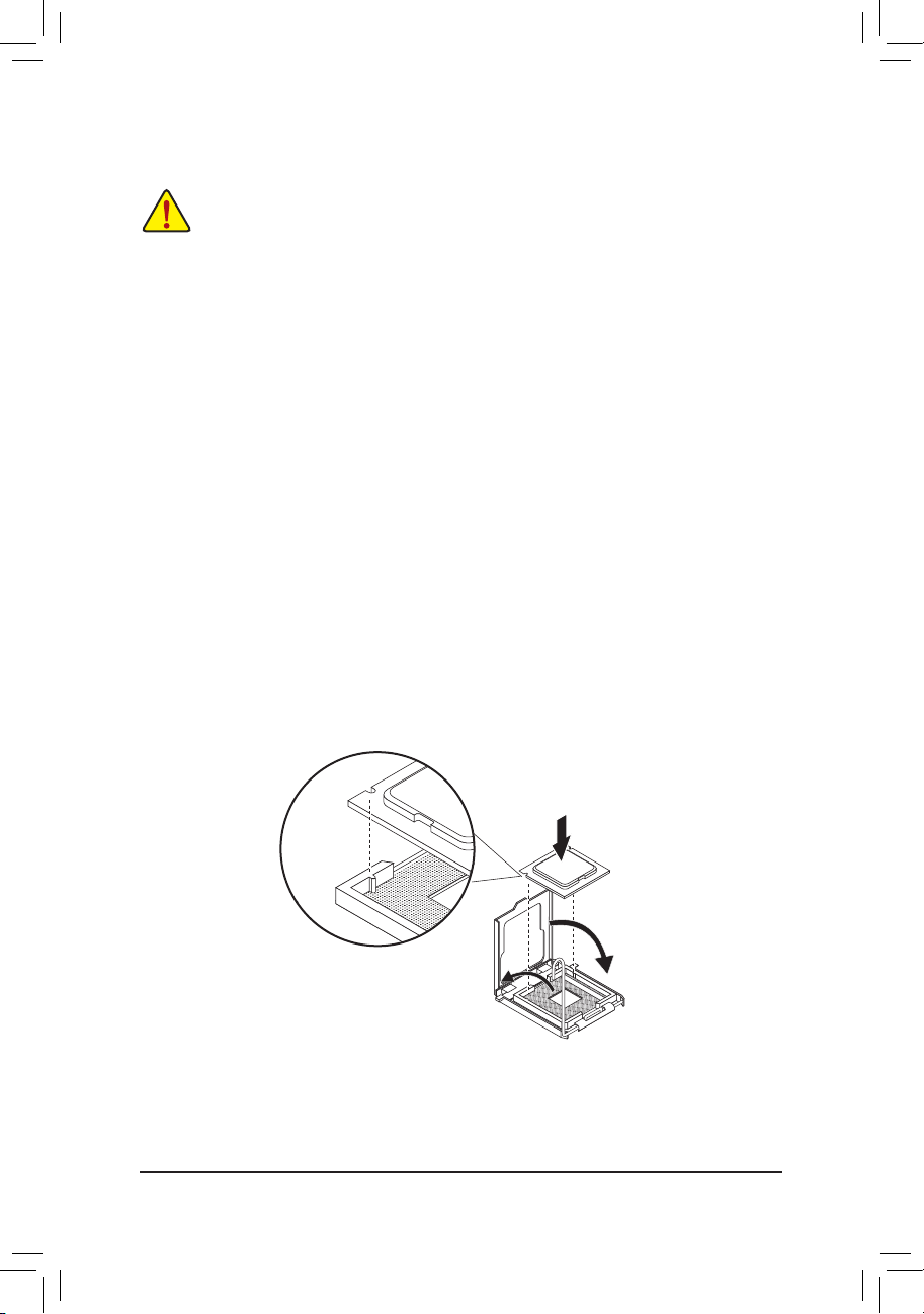
1-3-1 Installing the CPU
Step 1. Raise the metal locking lever on the socket.
Step 2. Remove the plastic covering on the CPU socket.
Step 3. Lift the metal cover.
Step 4. Insert the CPU with the correct orientation. The CPU only ts in one orientation.
Step 5. Please replace the metal cover and push the metallever back into locked position.
- 17 -
Page 18
Hardware Installation
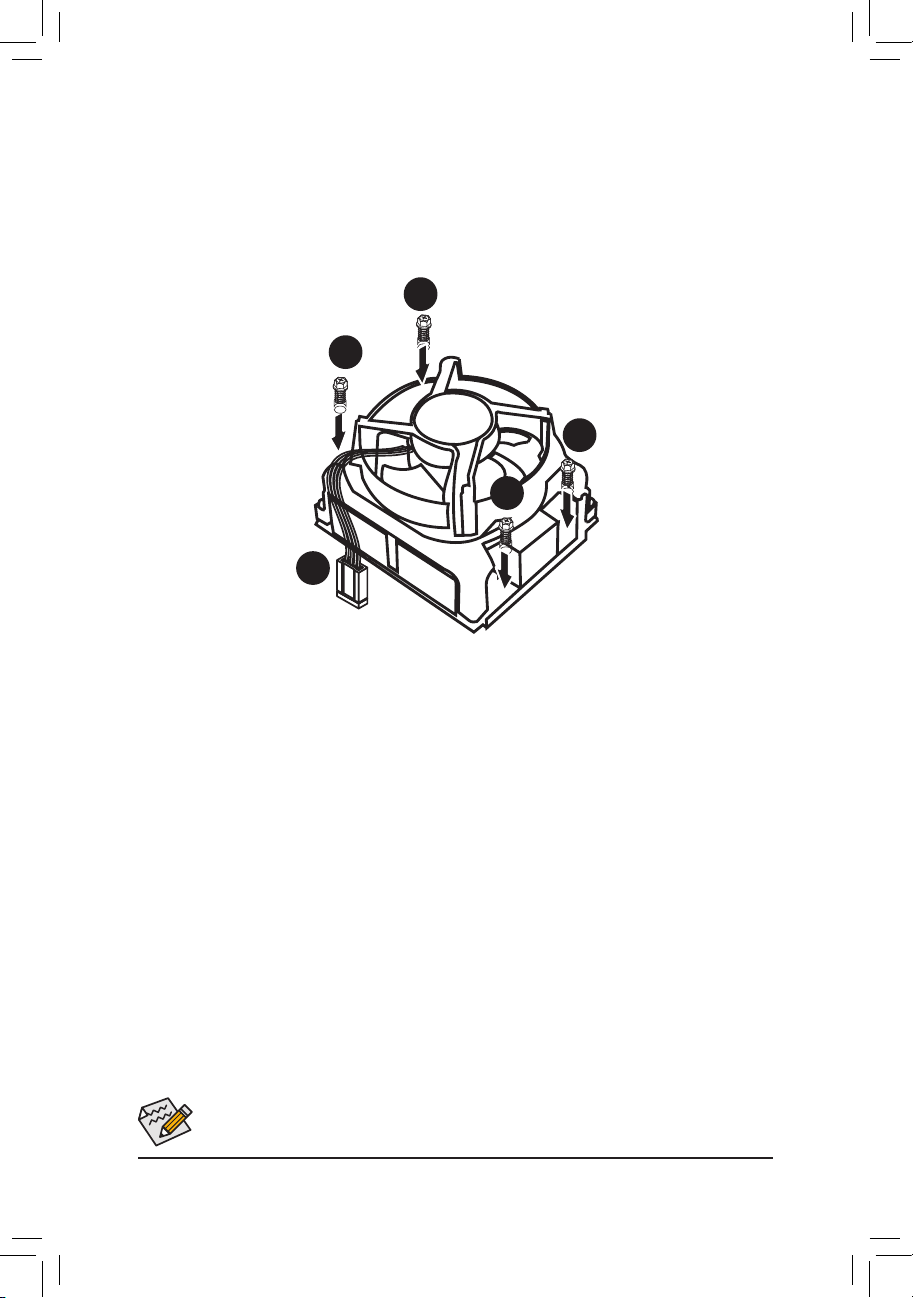
1-3-2 Installing the CPU Cooler
Follow the steps below to correctly install the CPU cooler on the motherboard.
Step 1. Attach the heat sink clip to the processor socket.
Step 2. Secure the cooing fan with screws..
Step 3. Connect processor fan can cable to the processor fan connector.
1
1
1
1
2
Use extreme care when removing the CPU cooler because the thermal grease/tape between the
CPU cooler and CPU may adhere to the CPU. Inadequately removing the CPU cooler may damage
the CPU.
- 18 -
Page 19
Hardware Installation
1-4 Installing the Memory
Read the following guidelines before you begin to install the memory:
• Make sure that the motherboard supports the memory. It is recommended that memory of the
same capacity, brand, speed, and chips be used.
(
Go to GIGABYTE's website for the latest supported memory speeds and memory modules.
• Always turn off the computer and unplug the power cord from the power outlet before installing
the memory to prevent hardware damage.
• Memory modules have a foolproof design. A memory module can be installed in only one
direction. If you are unable to insert the memory, switch the direction.
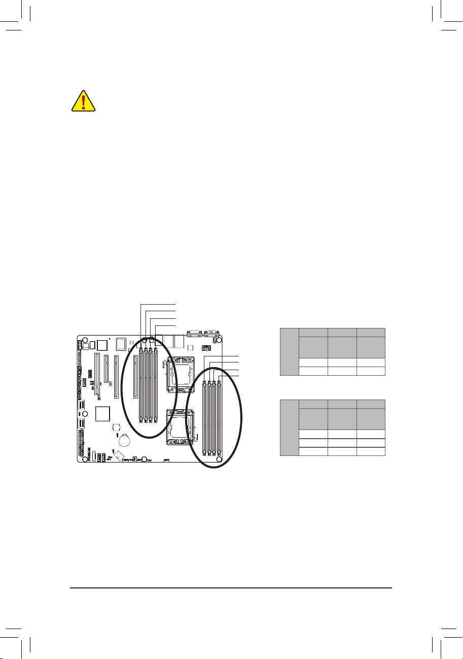
1-4-1 Dual/3ChannelMemoryConguration
This motherboard provides eight DDR3 memory sockets and supports Dual/3 Channel Technology. After the
memory is installed, the BIOS will automatically detect the specications and capacity of the memory. Enabling Dual Channel memory mode will double the original memory bandwidth.
The four DDR3 memory sockets are divided into two channels and each channel has two memory sockets as
following:
Channel A: DDR3_P0_A0, DDR3_P1_D0
Channel B: DDR3_P0_B0, DDR3_P1_E0
Channel C: DDR3_P0_C0, DDR3_P0_C1, DDR3_P1_F0,DDR3_P1_F1
DDR3_P1_D0
DDR3_P1_E0
DDR3_P1_F0
DDR3_P1_F1
DDR3_P0_C1
DDR3_P0_C0
DDR3_P0_B0
DDR3_P0_A0
U-DIMM
DDR3_P0_A0
DDR3_P1_D0
Channel B Channel C
Channel A
DDR3_P0_B0
DDR3_P1_E0
Single-Rank Single-Rank Single-Rank
Dual-Rank Dual-Rank Dual-Rank
DDR3_P0_C0
DDR3_P0_C1
DDR3_P1_F0
DDR3_P1_F1
)
GA-7PCSL
Channel A
Channel B Channel C
DDR3_P0_B0
DDR3_P1_E0
Single-Rank Single-Rank Single-Rank
Dual-Rank Dual-Rank Dual-Rank
Quad-Rank Quad-Rank Quad-Rank
R-DIMM
DDR3_P0_A0
DDR3_P1_D0
DDR3_P0_C0
DDR3_P0_C1
DDR3_P1_F0
DDR3_P1_F1
Due to CPU limitation, read the following guidelines before installing the memory in Dual or 3 Channel mode
Dual Channel--
1. Dual Channel mode cannot be enabled if only one DDR3 memory module is installed.
2. When enabling Dual Channel mode with two or four modules, it is recommended that memory of th
same capacity, brand, speed, and chips be used. When enabling Dual Channel mode with two
memory modules, be sure to install them in the DDR3_P0_C0 and DDR3_P0_C1 sockets for primary
CPU; install DDR3_P1_F0 and DDR3_P1_F1 for secondary CPU.
3 Channel--
1. 3 Channel mode cannot be enabled if only one or two DDR3 memory modules are installed.
2. When enabling 3 Channel mode with three, four or six modules, it is recommended that memory of
the same capacity, brand, speed, and chips be used. When enabling 3 Channel mode with three
- 19 -
Page 20
Hardware Installation
memory modules, be sure to install them in the DDR3_P0_A0, DDR3_P0_B0 and DDR3_P0_C0
sockets for primary CPU; install DDR3_P1_D0, DDR3_P1_E0 DDR3_P1_F0 for secondary CPU.
When enabling 3 Channel mode with four memory modules, be sure to install them in the
DDR3_P0_A0, DDR3_P0_B0, DDR3_P0_C0, and and DDR3_P0_C1 sockets for primary CPU; install
DDR3_P1_D0, DDR3_P1_E0, DDR3_P1_F0, and DDR3_P1_F1 for secondary CPU
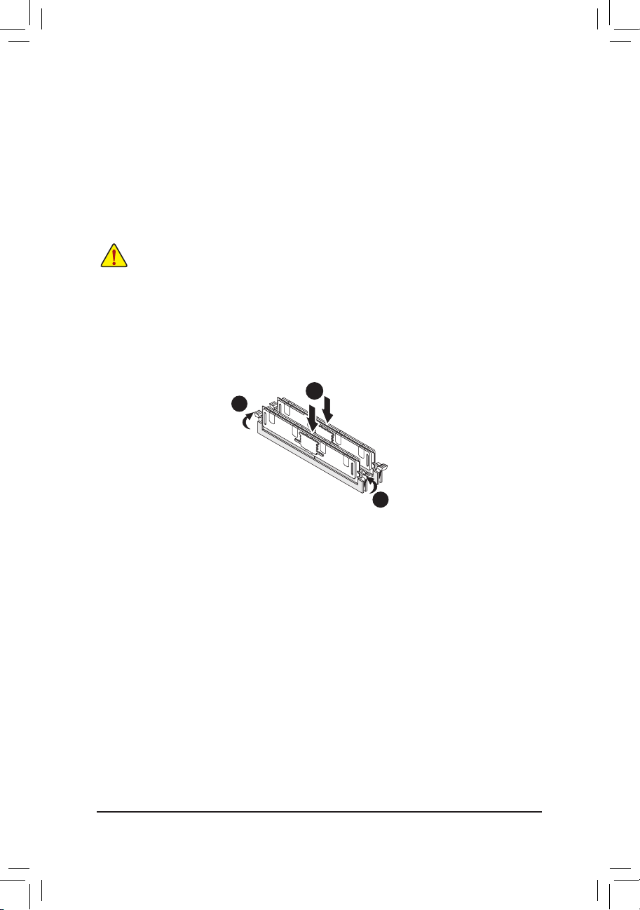
1-4-2 Installing a Memory
Before installing a memory module, make sure to turn off the computer and unplug the power
cord from the power outlet to prevent damage to the memory module.
Be sure to install DDR3 DIMMs on this motherboard.
Installation Step:
Step 1. Insert the DIMM memory module vertically into the DIMM slot, and push it down.
Step 2. Close the plastic clip at both edges of the DIMM slots to lock the DIMM module.
Note: For dual-channel operation, DIMMs must be installed in matched pairs.
Step 3. Reverse the installation steps when you wish to remove the DIMM module.
2
1
2
- 20 -
Page 21
Hardware Installation
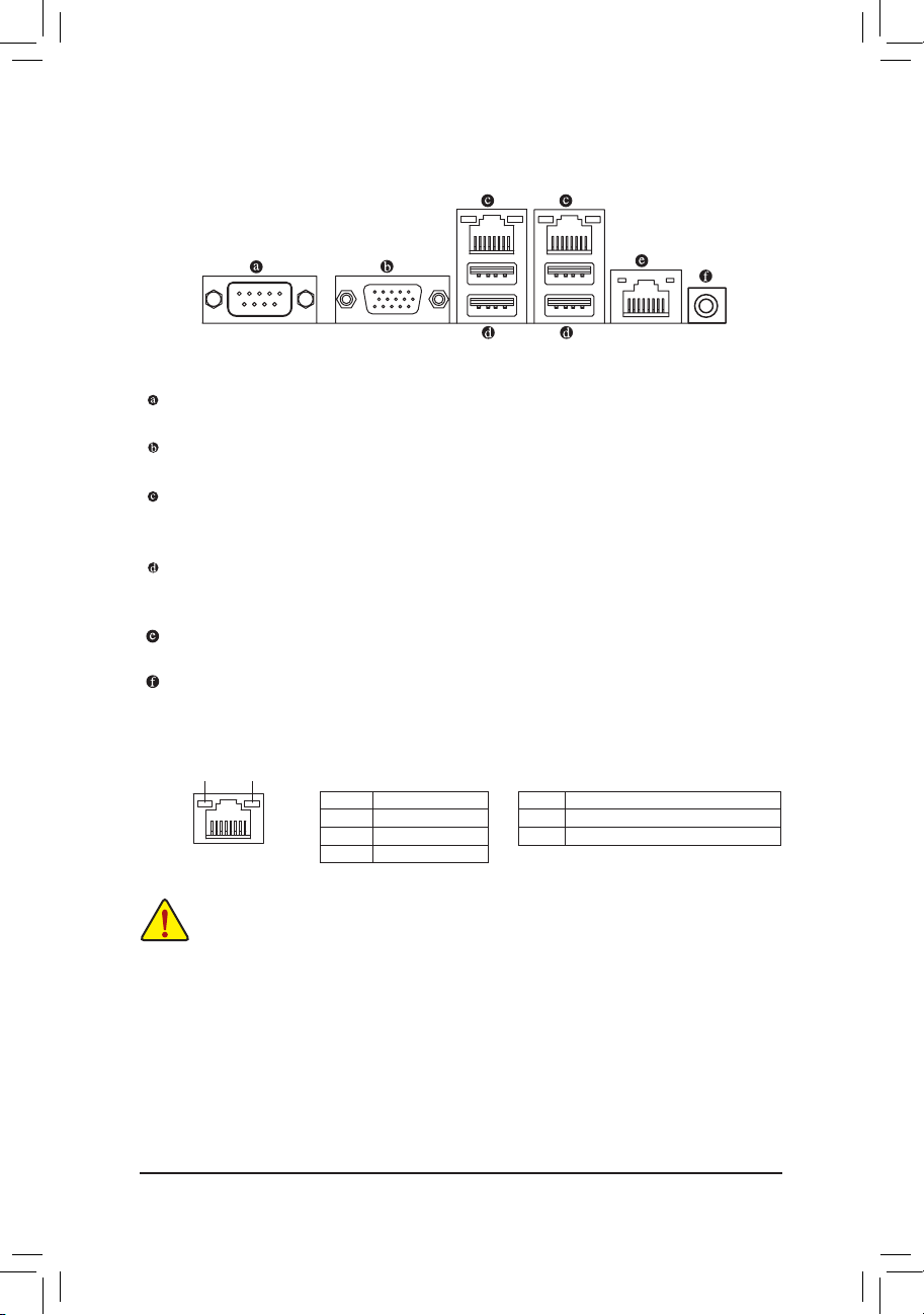
1-5 Back Panel Connectors
Serial Port
Connects to serial-based mouse or data processing devices.
Video Port
The video in port allows connect to video in, which can also apply to video loop thru function.
RJ-45 LAN Port
The Gigabit Ethernet LAN port provides Internet connection at up to 1 Gbps data rate. The following
describes the states of the LAN port LEDs.
USB 2.0/1.1 Port
The USB port supports the USB 2.0/1.1 specication. Use this port for USB devices such as a USB keyboard/mouse, USB printer, USB ash drive and etc.
KVM Server Management 10/100 LAN Port
The LAN port provides Internet connection with data transfer speeds of 10/100Mbps.
ID Switch Button
This button provide the selected unit idencation function.
Connection/
Speed LED
LAN Port
Activity LED
State Description
Orange 1 Gb ps data rate
Green 100 Mbps data r ate
Off 10 Mbps data rate
Activity LED:Connection/Speed LED:
State Description
Blinking Data transmission or receiving is occurring
On No data tr ansmission
• When removing the cable connected to a back panel connector, rst remove the cable from your
device and then remove it from the motherboard.
• When removing the cable, pull it straight out from the connector. Do not rock it side to side to
prevent an electrical short inside the cable connector.
- 21 -
Page 22
Hardware Installation
1-6 Internal Connectors
GA-7PCSL
14
19
21
24
13
15
12
18
16
17
1
22
11
2
10
1) ATX1
2) P12V_AUX1
3) P12V_AUX2
4) CPU0_FAN (for primary CPU)
5) CPU1_FAN (for seconary CPU)
6) SYS_FAN4 (System Fan)
7) SYS_FAN3 (System Fan)
8) SYS_FAN2 (System Fan)
9) SYS_FAN1 (System Fan)
10) PMbus_CN_1
11) SATA0/1
12) F_USB1
5
3
20
23
678
9
4
13) COM2
14) SCU_SGPIO
15) FP_1
16) MINISAS_1
17) MINISAS_2
18) SAS0/1/2/3
19) IPMB
20) BAT
21) TPM_MEZZ1
22) BP_1
23) SKU_KEY1
24) BMC_LED1
- 22 -
Page 23
Hardware Installation
GA-7PCSLX
13
21
19
24
35
15
12
18
16
14
25
17
22
11
9
10
1) ATX1
2) P12V_AUX1
3) P12V_AUX2
4) CPU0_FAN (for primary CPU)
5) CPU1_FAN (for seconary CPU)
6) SYS_FAN4 (System Fan)
7) SYS_FAN3 (System Fan)
8) SYS_FAN2 (System Fan)
9) SYS_FAN1 (System Fan)
10) PMbus_CN_1
11) SATA0/1
12) F_USB1
13) COM2
8
20
23
467
14) SCU_SGPIO
15) FP_1
16) MINISAS_1
17) SATA2/3/4/5
18) SAS0/1/2/3
19) IPMB
20) BAT
21) TPM_MEZZ1
22) BP_1
23) SKU_KEY1
24) BMC_LED1
25) SATA_SGPIO
1
2
Read the following guidelines before connecting external devices:
• First make sure your devices are compliant with the connectors you wish to connect.
• Before installing the devices, be sure to turn off the devices and your computer. Unplug the
• After installing the device and before turning on the computer, make sure the device cable has
power cord from the power outlet to prevent damage to the devices.
been securely attached to the connector on the motherboard.
- 23 -
Page 24
Hardware Installation
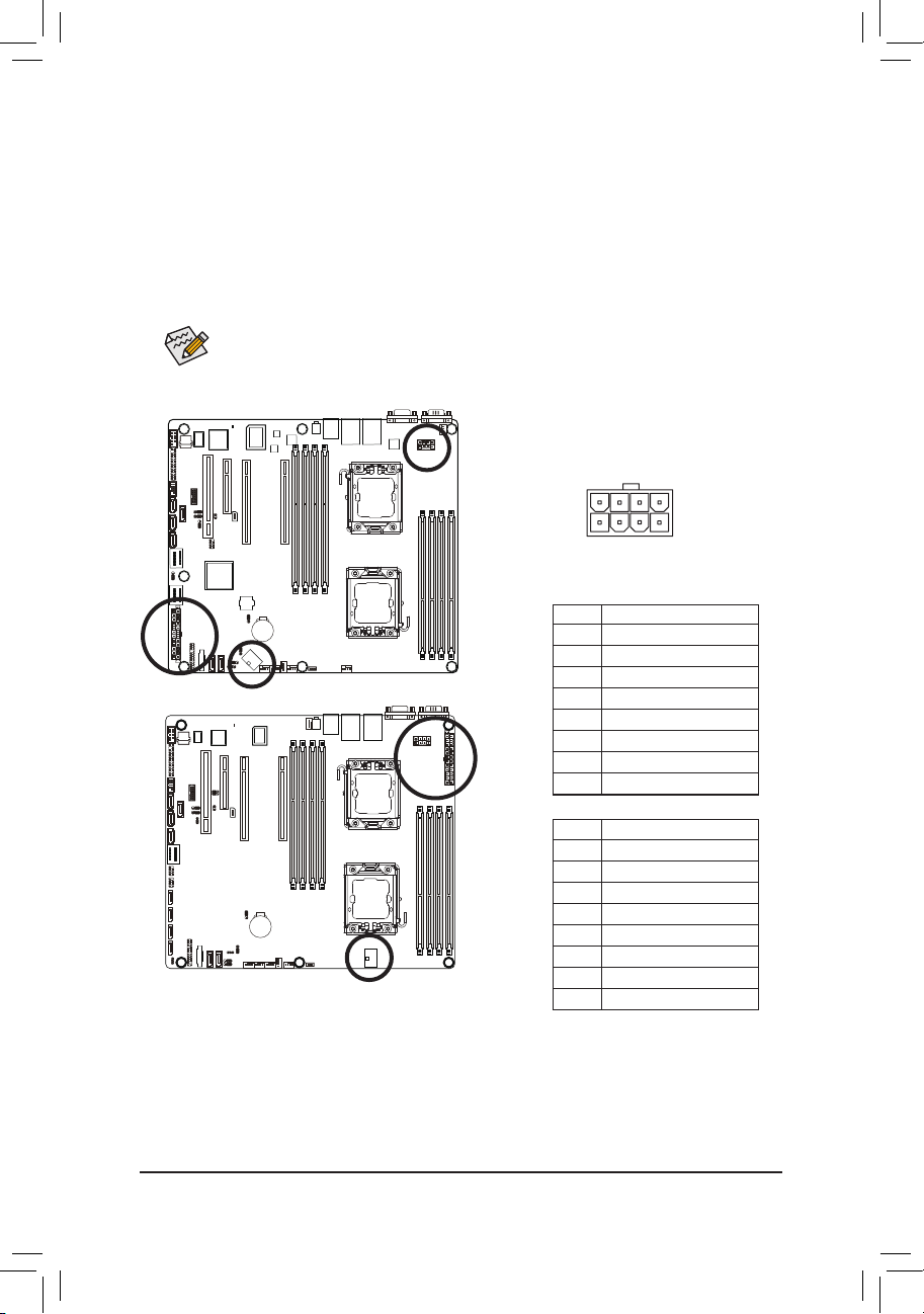
1/2/3) ATX1/P12V_AUX1/P12V_AUX2
(2x4 12V Power Connector and 2x12 Main Power Connector)
With the use of the power connector, the power supply can supply enough stable power to all the com-
ponents on the motherboard. Before connecting the power connector, rst make sure the power supply
is turned off and all devices are properly installed. The power connector possesses a foolproof design.
Connect the power supply cable to the power connector in the correct orientation. The 12V power connector mainly supplies power to the CPU. If the 12V power connector is not connected, the computer will
not start.
To meet expansion requirements, it is recommended that a power supply that can withstand high
power consumption be used (500W or greater). If a power supply is used that does not provide
the required power, the result can lead to an unstable or unbootable system.
P12V_AUX1
P12V_AUX2
85
GA-7PCSL
GA-7PCSLX
41
P12V_AUX1
Pin No. Denition
1 GND
2 GND
3 GND
4 GND
5 P12V_DDR3_CPU0
6 P12V_DDR3_CPU0
7 P12V_CPU0
8 P12V_CPU0
P12V_AUX2
Pin No. Denition
1 GND
2 GND
3 GND
4 GND
5 P12V_DDR3_CPU1
6 P12V_DDR3_CPU1
7 P12V_CPU1
8 P12V_CPU1
- 24 -
Page 25
Hardware Installation
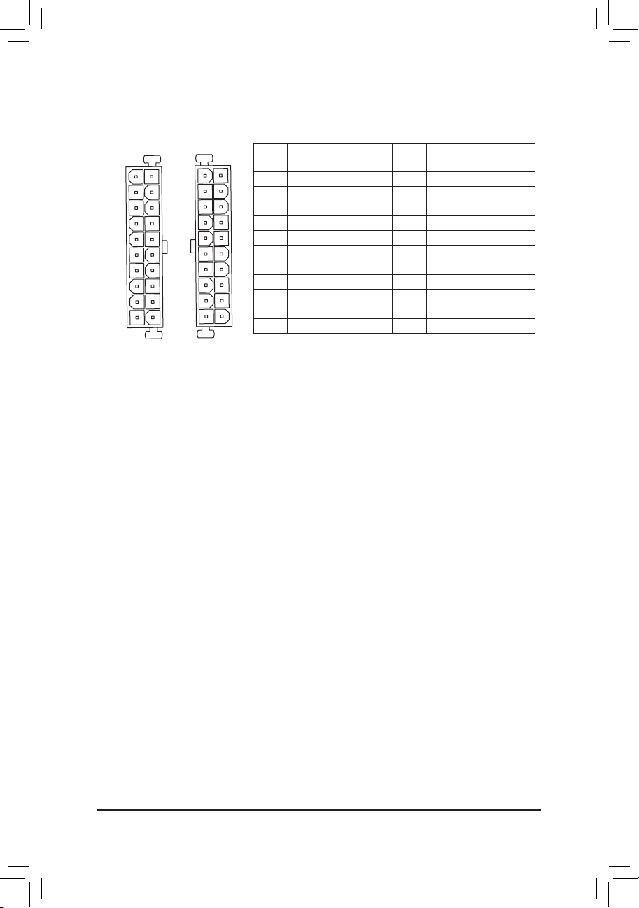
ATX1
ATX
(GA-7PCSL)
12
1
ATX1
(GA-7PCSLX)
24
13
13
24
ATX1
1
Pin No. Denition
1 3.3V
2 3.3V
3 GND
4 +5V
5 GND
6 +5V
7 GND
8 Power Good
9 5VSB (stand by +5V)
10 +12V
11 +12V (Only for 2x12-pin ATX)
12 3.3V (Only for 2x12-pin ATX)
12
Pin No. Denition
13 3.3V
14 -12V
15 GND
16 PS_ON (soft On/Off)
17 GND
18 GND
19 GND
20 -5V
21 +5V
22 +5V
23 +5V (Only for 2x12-pin ATX)
24 GND (Only for 2x12-pin ATX)
- 25 -
Page 26
Hardware Installation
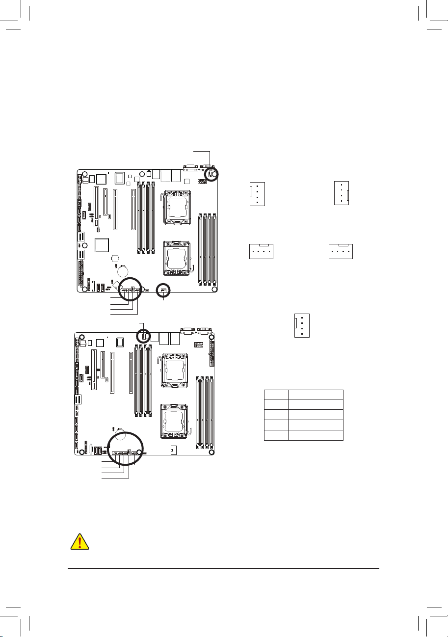
4/5/6/7/8/9) CPU0_FAN/CPU1_FAN/SYS_FAN4/SYS_FAN3/SYS_FAN2/SYS_FAN1
DEBUG
PORT
DEBUG
PORT
DEBUG
PORT
DEBUG
PORT
(CPU Fan/System Fan Headers)
The motherboard has a 4-pin CPU fan header (CPU_FAN1/2), a 4-pin (FAN4) system fan headers. Most
fan headers possess a foolproof insertion design. When connecting a fan cable, be sure to connect it in
the correct orientation (the black connector wire is the ground wire). The motherboard supports CPU fan
speed control, which requires the use of a CPU fan with fan speed control design. For optimum heat dissipation, it is recommended that a system fan be installed inside the chassis.
CPU1_FAN
1
1
CPU1_FAN
(GA-7PCSLX)
GA-7PCSL
CPU1_FAN
SYS_FAN3
(GA-7PCSL)
1
SYS_FAN1
SYS_FAN2
SYS_FAN3
SYS_FAN4
CPU1_FAN
CPU0_FAN
GA-7PCSLX
CPU0_FAN
SYS_FAN1
SYS_FAN2
SYS_FAN4
(GA-7PCSL)
Pin No. Denition
SYS_FAN4
(GA-7PCSLX)
1
CPU0_FAN
SYS_FAN1
SYS_FAN2
SYS_FAN3
(GA-7PCSLX)
1 GND
2 +12V
3 Sense
4 Speed Control
SYS_FAN1
SYS_FAN2
SYS_FAN3
SYS_FAN4
CPU0_FAN
• Be sure to connect fan cables to the fan headers to prevent your CPU and system from
overheating. Overheating may result in damage to the CPU or the system may hang.
• These fan headers are not configuration jumper blocks. Do not place a jumper cap on the
headers.
- 26 -
1
Page 27
Hardware Installation
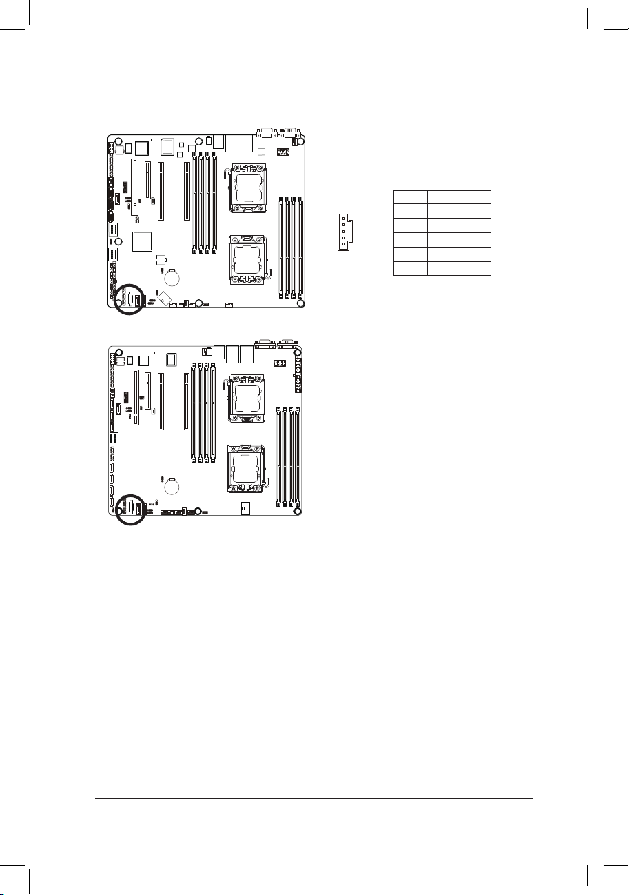
10) PMbus_CN_1 (Power management connector)
GA-7PCSL
GA-7PCSLX
5
1
Pin No. Denition
1 SMB CLK
2 SMB DATA
3 SMB Alert
4 GND Sense
5 3.3V Sense
- 27 -
Page 28
Hardware Installation
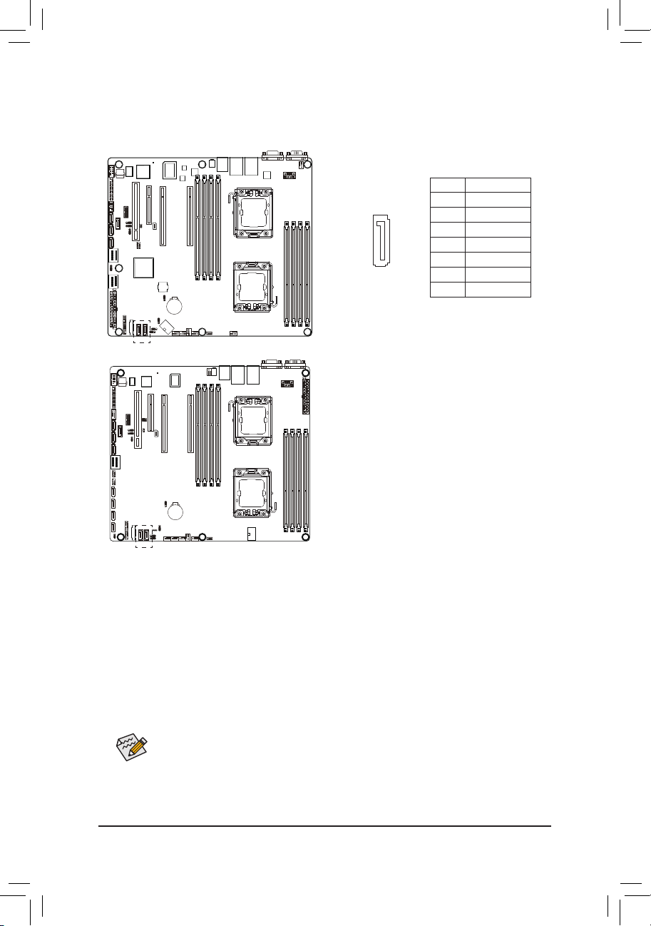
11) SATA0/1 (SATA 6Gb/s Connectors)
DEBUG
PORT
G.QBOFM
The SATA connectors conform to SATA 6Gb/s standard and are compatible with SATA 3Gb/s standard.
Each SATA connector supports a single SATA device.
Pin No. Denition
7
GA-7PCSL
1
GA-7PCSLX
1 GND
2 TXP
3 TXN
4 GND
5 RXN
6 RXP
7 P5V/GND
• A RAID 0 or RAID 1 conguration requires at least two hard drives. If more than two hard
drives are congured, the total number of hard drives must be an even number.
• A RAID 10 conguration requires four hard drives.
(Note) When a RAID conguration is built across the SATA 3Gb/s channels, the system performance of
the RAID conguration may vary depends on the devices are connected.
- 28 -
Page 29

Hardware Installation
12) F_USB1 (USB Headers)
The headers conform to USB 2.0/1.1 specication. Each USB header can provide two USB ports via an
optional USB bracket. For purchasing the optional USB bracket, please contact the local dealer.
Pin No. Denition
1 Power (5V)
2 Power (5V)
3 USB DX-
4 USB DY-
5 USB DX+
6 USB DY+
7 GND
8 GND
9 No Pin
10 NC
GA-7PCSL
GA-7PCSLX
1 2
9 10
- 29 -
Page 30

Hardware Installation
13) COM2 (Serial Port Header)
The COM header can provide one serial port via an optional COM port cable. For purchasing the op-
tional COM port cable, please contact the local dealer.
GA-7PCSL
GA-7PCSLX
21
109
Pin No. Denition
1 NDCD-
2 NDSR-
3 NSIN
4 NRTS-
5 NSOUT
6 NCTS-
7 NDTR-
8 NRI-
9 GND
10 No Pin
- 30 -
Page 31

Hardware Installation
14) SCU_SGPIO (SCU SGPIO Header)
SGPIO is stands for Serial General Purpose Input/Output which is a 4-signal (or 4-wire) bus used be-
tween a Host Bus Adapter (HBA) and a backplane. Out of the 4 signals, 3 are driven by the HBA and 1 is
driven by the backplane. Typically, the HBA is a storage controller located inside a server, desktop, rack
or workstation computer that interfaces with Hard disk drives (HDDs) to store and retrieve data.
Pin No. Denition
1 SGPIO_SAS1_DATAIN
2 No Pin
3 SGPIO_SAS1_DATAOUT
4 GND
5 GND
6 SGPIO_SAS1_LOAD
7 NC
8 SGPIO_SAS1_CLOCK
GA-7PCSL
GA-7PCSLX
10
291
- 31 -
Page 32

Hardware Installation
15) FP_1 (Front Panel Header/GA-7PCSL)
Connect the power switch, reset switch, speaker, chassis intrusion switch/sensor and system status
indicator on the chassis to this header according to the pin assignments below. Note the positive and
negative pins before connecting the cables.
1 2
GA-7PCSL
12 24
Pin No. Signal Name Denition
1 PWLED+ Power LED Signal anode (+)
2 5VSB 5V Stanndby Power
3 NC No Pin
4 ID_LED+ ID LED Signal anode (+)
5 PWLED- Power LED Signal cathode(-)
6 ID_LED- ID LED Signal cathode(-)
7 HD+ Hard Disk LED Signal anode (+)
8 F_SYSRDY System Front board LED Signal
9 HD- (GND) Ground
10 SYS_STATUS- System Status LED Signal cathode(-)
11 PWB+ Power Button Signal anode (+)
12 L2_ACT LAN2 active LED Signal
13 PWB+_GND Ground
14 L2_LINK- LAN2 Link LED Signal cathode(-)
15 RST_BTN+ Reset button Signal anode (+)
16 SENSOR_SDA SMBus Data Signal
17 RST_BTN_GND Ground
18 SENSOR_SCL SMBus Clock Signal
19 ID_SW+ ID Switch Signal anode (+)
20 CASE_OPEN- Chassis intrusion Signal cathode(-)
21 ID_SW (GND) Ground
22 L1_ACT LAN1 active LED Signal
23 NMI_SW- NMI switch Signal cathode(-)
24 L1_LINK- LAN1 Link LED Signal cathode(-)
- 32 -
Page 33

Hardware Installation
15) FP_1 (Front Panel Header/GA-7PCSLX)
GA-7PCSLX
Pin No. Signal Name Denition
1 PWLED+ Power LED Signal anode (+)
2 5VSB 5V Stanndby Power
3 NC No Pin
4 ID_LED+ ID LED Signal anode (+)
5 PWLED- Power LED Signal cathode(-)
6 ID_LED- ID LED Signal cathode(-)
7 HD+ Hard Disk LED Signal anode (+)
8 F_SYSRDY System Front board LED Signal
9 HD- (GND) Ground
10 SYS_STATUS- System Status LED Signal cathode(-)
11 PWB+ Power Button Signal anode (+)
12 L1_ACT LAN1 active LED Signal
13 PWB+_GND Ground
14 L1_LINK- LAN1 Link LED Signal cathode(-)
15 RST_BTN+ Reset button Signal anode (+)
16 SENSOR_SDA SMBus Data Signal
17 RST_BTN_GND Ground
18 SENSOR_SCL SMBus Clock Signal
19 ID_SW+ ID Switch Signal anode (+)
20 CASE_OPEN- Chassis intrusion Signal cathode(-)
21 ID_SW (GND) Ground
22 L2_ACT LAN2 active LED Signal
23 NMI_SW- NMI switch Signal cathode(-)
24 L2_LINK- LAN2 Link LED Signal cathode(-)
1 2
12 24
The front panel design may differ by chassis. A front panel module mainly consists of power switch,
reset switch, power LED, hard drive activity LED, speaker and etc. When connecting your chassis
front panel module to this header, make sure the wire assignments and the pin assignments are
matched correctly.
- 33 -
Page 34

Hardware Installation
16) MINISAS_1 (Mini SAS cable connector)
The mini SAS connectors conform to SATA 3Gb/s standard.
17) MINISAS_2 (Mini SAS cable connector with SATA 3Gb/s signal/GA-7PCSL Only)
The SATA connectors conform to SATA 3Gb/s standard and are compatible with SATA 1.5Gb/s standard.
Each SATA connector supports two SATA device.
MINISAS_1
A1 B1
GA-7PCSL
A18 B18
MINISAS_2
MINISAS_1 MINISAS_2
Pin No. Denition
A1 GND
A2 RX0+
A3 RX0-
A4 GND
A5 RX1+
A6 RX1-
A7 GND
A8 SIB7
A9 SIB3
A10 SIB4
A11 SIB5
A12 GND
A13 RX2+
A14 RX2-
A15 GND
A16 RX3+
A17 RX3-
A18 GND
Pin No. Denition
B1 GND
B2 TX0+
B3 TX0-
B4 GND
B5 TX1+
B6 TX1-
B7 GND
B8 SIB0
B9 SIB1
B10 SIB2
B11 SIB6
B12 GND
B13 TX2+
B14 TX2-
B15 GND
B16 TX3+
B17 TX3-
A18 GND
Pin No. Denition
A1 GND
A2 RX0+
A3 RX0-
A4 GND
A5 RX1+
A6 RX1-
A7 GND
A8 SIB7
A9 SIB3
A10 SIB4
A11 SIB5
A12 GND
A13 RX2+
A14 RX2-
A15 GND
A16 RX3+
A17 RX3-
A18 GND
Pin No. Denition
B1 GND
B2 TX0+
B3 TX0-
B4 GND
B5 TX1+
B6 TX1-
B7 GND
B8 SIB0
B9 SIB1
B10 SIB2
B11 SIB6
B12 GND
B13 TX2+
B14 TX2-
B15 GND
B16 TX3+
B17 TX3-
B18 GND
- 34 -
Page 35

Hardware Installation
17) SATA2/3/4/5 (SATA 3Gb/s Connectors)
DEBUG
PORT
G.QBOFM
The SATA connectors conform to SATA 3Gb/s standard and are compatible with SATA 1.5Gb/s standard.
Each SATA connector supports a single SATA device.
Pin No. Denition
7
1 GND
2 TXP
3 TXN
GA-7PCSLX
1
4 GND
5 RXN
6 RXP
7 GND
- 35 -
Page 36

Hardware Installation
18) SAS0/1/2/3 (SAS cable connectors)
DEBUG
PORT
G.QBOFM
The SAS connectors conform to SATA 3Gb/s standard.
GA-7PCSL
GA-7PCSLX
Pin No. Denition
7
1
1 GND
2 TX+
3 TX-
4 GND
5 R-
6 R+
7 GND
- 36 -
Page 37

Hardware Installation
19) IPMB (IPMB connector)
GA-7PCSL
GA-7PCSLX
1
3
Pin No. Denition
1 SCL
2 GND
3 SDA
- 37 -
Page 38

Hardware Installation
20) BAT (Battery)
The battery provides power to keep the values (such as BIOS congurations, date, and time information)
in the CMOS when the computer is turned off. Replace the battery when the battery voltage drops to a
low level, or the CMOS values may not be accurate or may be lost.
GA-7PCSL
You may clear the CMOS values by removing the battery:
1. Turn off your computer and unplug the power cord.
2. Gently remove the battery from the battery holder and wait for
one minute. (Or use a metal object like a screwdriver to touch
the positive and negative terminals of the battery holder, making
them short for 5 seconds.)
3. Replace the battery.
4. Plug in the power cord and restart your computer.
GA-7PCSLX
• Always turn off your computer and unplug the power cord before replacing the battery.
• Replace the battery with an equivalent one. Danger of explosion if the battery is replaced with an incorrect model.
• Contact the place of purchase or local dealer if you are not able to replace the battery by yourself or uncertain about the battery
model.
• When installing the battery, note the orientation of the positive side (+) and the negative side (-) of the battery (the positive side
should face up).
• Used batteries must be handled in accordance with local environmental regulations.
- 38 -
Page 39

Hardware Installation
21) TPM_MEZZ1 (TPM Module)
GA-7PCSL
GA-7PCSLX
13114
Pin No. Denition
2
1 CLK_33M_TPM
2 P_3V3_AUX
3 LPC_RST_DEBUG
4 P3V3
5 LPC_LAD0
6 IRQ_SERIAL
7 LPC_LAD1
8 TPM_DET_N
9 LPC_LAD2
10 NC
11 LPC_LAD3
12 GND
13 LPC_FRAME_N
14 GND
- 39 -
Page 40

Hardware Installation
22) BP1 (Back Plane Board Hearder)
GA-7PCSL
GA-7PCSLX
1 2
Pin No. Denition
1 AST2300_SCGCLK
2 FM_THROTTLE_AND_N
3 AST2300_SGLD
4 IQO_FAN_12v_GATE_N
5 AST2300_SGDOUT
6 GND
7 KEY
8 RresetL_BRB
25 26
9 GND
10 BP_ALED_N
11 BP_LED_G_N
12 GND
13 AST2300_SGDIN
14 ASSESS#_LED_BPB
15 GND
16 SMB_BPB1_DATA
17 GND
18 SMB_BPB1_CLK
19 GND
20 BP_HDD_TYPE
21 P_3V3_AUX
22 FAN_TYPE
23 P_3V3_AUX
24 KEY
25 BP_PRESENSE
26 GND
- 40 -
Page 41

Hardware Installation
23) SKU_KEY1 (Patsburg Upgrade ROM Hearder)
GA-7PCSL
GA-7PCSLX
13
Pin No. Denition
1 GND
2 FM_PBG_DYN_SKU_KEY
3 GND
- 41 -
Page 42

Hardware Installation
24) BMC_LED1 (BMC Firmware Readiness LED)
GA-7PCSL
GA-7PCSLX
State Description
On BMC rmware is initial
Blinking BM C rmwa re is ready
Off System AC is pow ered off
- 42 -
Page 43

Hardware Installation
25) SATA_SGPIO (SATA SGPIO Header/GA-7PCSLX Only)
1029
GA-7PCSLX
1
Pin No. Denition
1 SGPIO_SAS1_DATAIN
2 No Pin
3 SGPIO_SAS1_DATAOUT
4 GND
5 GND
6 SGPIO_SAS1_LOAD
7 NC
8 SGPIO_SAS1_CLOCK
- 43 -
Page 44

Hardware Installation
1-7 Jumper Setting
GA-7PCSL
1
2
3
4
5
6
8 9
7
1) JP5
2) PASSWORD
3) BIOS_RVCR
4) SSB_ME1
5) SSB_ME2
6) CLR_CMOS
7) SATA_DOM1
8) SATA_DOM0
9) BIOS_WP
- 44 -
Page 45

Hardware Installation
GA-7PCSLX
3
4
1
6
5
10
2
7
8
9
1) JP5
2) PASSWORD
3) BIOS_RCVR
4) SSB_ME1
5) SSB_ME2
6) CLR_CMOS
7) SATA_DOM1
8) SATA_DOM0
9) BIOS_WP
10) ROMST_FRB3
- 45 -
Page 46

Hardware Installation
1) JP5 (Case Open Intrusion Jumper)
Open: Normal operation. (Default setting)
GA-7PCSL
GA-7PCSLX
Close: Enable chassis intrusion alert.
- 46 -
Page 47

Hardware Installation
2) PASSWORD (Skip Supervisor Password Jumper)
1
1
GA-7PCSL
GA-7PCSLX
1-2 Close: Normal operation. (Default setting)
2-3 Close: Skip supervisor password.
- 47 -
Page 48

Hardware Installation
3) BIOS_RVCR (BIOS Recovery Jumper/GA-7PCSL)
1
1
GA-7PCSL
3) BIOS_RCVR (BIOS Recovery Jumper/GA-7PCSLX)
1
1-2 Close: Normal operation. (Default setting)
2-3 Close: BIOS recovery mode.
1-2 Close: Normal operation. (Default setting)
GA-7PCSLX
1
2-3 Close: BIOS recovery mode.
- 48 -
Page 49

Hardware Installation
4/5) SSB_ME1/SSB_ME2 (ME enable/disable Jumper)
SSB_ME1
1
1-2 Close: Normal operation. (Default setting)
1
GA-7PCSL
GA-7PCSLX
2-3 Close: Disable ME function.
SSB_ME2
1
1-2 Close: Disable ME function.
1
2-3 Close: Normal operation. (Default setting)
- 49 -
Page 50

Hardware Installation
6) CLR_CMOS (Clearing CMOS Jumper)
Use this jumper to clear the CMOS values (e.g. date information and BIOS congurations) and reset
the CMOS values to factory defaults. To clear the CMOS values, place a jumper cap on the two pins to
temporarily short the two pins or use a metal object like a screwdriver to touch the two pins for a few
seconds.
1
1-2 Close: Normal operation (Default setting)
1
2-3 Close: Clear CMOS data.
GA-7PCSL
GA-7PCSLX
• Always turn off your computer and unplug the power cord from the power outlet before clearing the CMOS
values.
• After clearing the CMOS values and before turning on your computer, be sure to remove the jumper cap from
the jumper. Failure to do so may cause damage to the motherboard.
• After system restart, go to BIOS Setup Exit menu and load factory defaults (select Load Setup Default) or
manually congure the BIOS settings (refer to Chapter 2, "BIOS Setup," for BIOS congurations).
- 50 -
Page 51

Hardware Installation
7/8) SATA_DOM0/1 (SATA DOM Jumper)
1
1-2 Close: Use SATA DOM.
GA-7PCSL
GA-7PCSLX
1
2-3 Close: Normal mode. (Default setting)
- 51 -
Page 52

Hardware Installation
9) BIOS_WP (BIOS Write Protect Jumper)
1-2 Close: Normal operation.
1
GA-7PCSL
GA-7PCSLX
2-3 Close: Enable BIOS write protect function.
1
(Default setting)
- 52 -
Page 53

Hardware Installation
10) ROMST_FRB3 (Force to Stop FRB3 Timer Jumper/GA-7PCSLX Only)
6
2
1 5
Pin No. Denition
GA-7PCSLX
1-3 Close: Normal ROM Strap
2-4 Close: Normal operation.
4-6 Close: Force to stop FRB3 Timer.
1 SGPIO_IBMC_DOUT_PD
2 BMC_FRB3_SB3V
3 SGPIO_IBMC_DATOUT
4 BMC_R_FRB3
5 p_3V3_AUX
6 GND
- 53 -
Page 54

BIOS Setup
Chapter 2 BIOS Setup
BIOS (Basic Input and Output System) records hardware parameters of the system in the EFI on the motherboard. Its major functions include conducting the Power-On Self-Test (POST) during system startup,
saving system parameters and loading operating system, etc. BIOS includes a BIOS Setup program that
allows the user to modify basic system conguration settings or to activate certain system features. When the
power is turned off, the battery on the motherboard supplies the necessary power to the CMOS to keep the
conguration values in the CMOS.
To access the BIOS Setup program, press the <F2> key during the POST when the power is turned on.
• BIOS ashing is potentially risky, if you do not encounter problems of using the current BIOS
version, it is recommended that you don't ash the BIOS. To ash the BIOS, do it with caution.
Inadequate BIOS ashing may result in system malfunction.
• It is recommended that you not alter the default settings (unless you need to) to prevent system
instability or other unexpected results. Inadequately altering the settings may result in system's
failure to boot. If this occurs, try to clear the CMOS values and reset the board to default values.
(Refer to the "Load Optimized Defaults" section in this chapter or introductions of the battery/
clearing CMOS jumper in Chapter 1 for how to clear the CMOS values.)
BIOS Setup Program Function Keys
<f><g> Move the selection bar to select the screen
<h><i> Move the selection bar to select an item
<Enter> Execute command or enter the submenu
<Esc> Main Menu: Exit the BIOS Setup program
Submenus: Exit current submenu
<F1> Show descriptions of general help
<F3> Restore the previous BIOS settings for the current submenus
<F9> Load the Optimized BIOS default settings for the current submenus
<F10> Save all the changes and exit the BIOS Setup program
- 54 -
Page 55

BIOS Setup
Main
This setup page includes all the items in standard compatible BIOS.
Advanced
This setup page includes all the items of AMI BIOS special enhanced features.
(ex: Auto detect fan and temperature status, automatically congure hard disk parameters.)
Chipset
This setup page includes all the submenu options for conguring the function of North Bridge and South
Bridge.
(ex: Auto detect fan and temperature status, automatically congure hard disk parameters.)
Security
Change, set, or disable supervisor and user password. Conguration supervisor password allows you to
restrict access to the system and BIOS Setup.
A supervisor password allows you to make changes in BIOS Setup.
A user password only allows you to view the BIOS settings but not to make changes.
Server Management
Server additional features enabled/disabled setup menus.
Boot Options
This setup page provides items for conguration of boot sequence.
Boot Manager
This setup page provides conguration of boot up devices.
Exit
Save all the changes made in the BIOS Setup program to the CMOS and exit BIOS Setup. (Pressing
<F10> can also carry out this task.)
Abandon all changes and the previous settings remain in effect. Pressing <Y> to the conrmation mes-
sage will exit BIOS Setup. (Pressing <Esc> can also carry out this task.)
- 55 -
Page 56

BIOS Setup
2-1 The Main Menu
Once you enter the BIOS Setup program, the Main Menu (as shown below) appears on the screen. Use
arrow keys to move among the items and press <Enter> to accept or enter other sub-menu.
Main Menu Help
The on-screen description of a highlighted setup option is displayed on the bottom line of the Main Menu.
Submenu Help
While in a submenu, press <F1> to display a help screen (General Help) of function keys available for the
menu. Press <Esc> to exit the help screen. Help for each item is in the Item Help block on the right side of
the submenu.
• When the system is not stable as usual, select the Load Default Values item to set your system
to its defaults.
• The BIOS Setup menus described in this chapter are for reference only and may differ by BIOS
version.
- 56 -
Page 57

BIOS Setup
BIOS Version
Display version number of the BIOS setup utility.
Memory
Determines how much total memory is present during the POST.
System Date
Set the date following the weekday-month-day- year format.
System Time
Set the system time following the hour-minute- second format.
Access Level
Display the current accessing level information.
- 57 -
Page 58

BIOS Setup
2-2 Advanced Menu
The Advanced menu display submenu options for conguring the function of various hardware components.
Select a submenu item, then press Enter to access the related submenu screen.
- 58 -
Page 59

BIOS Setup
2-2-1 PCIConguration
PCI Express Slot 1/2/3/4 Option ROM
When enabled, This setting will initialize the device expansion ROM for the related PCI-E slot.
Options available: Enabled/Disabled. Default setting is Enabled.
Onboard LAN1/2 Controller
Enable/Disable Onboard LAN controller .
Options available: Enabled/Disabled. Default setting is Enabled.
LAN1/2 Option ROM
Enable/Disable onboard LAN1 device and initialize device expansion ROM.
Options available: Enabled/Disabled. Default setting is Disabled.
PERR Generation
When this item is set to enabled, PCI bus parity error (PERR) is generated and is routed to NMI.
Options available: Enabled/Disabled. Default setting is Disabled.
SERR Generation
When this item is set to enabled, PCI bus system error (SERR) is generated and is routed to NMI.
Options available: Enabled/Disabled. Default setting is Disabled.
Maximum Playload
Set maximum playlooad for PCI Express Device or allow system BIOS to select the value.
Options available: Auto/128 Bytes/256 Bytes/512 Bytes/1024 Bytes/2048 Bytes/4096 Bytes.
Default setting is 4096 Bytes.
- 59 -
Page 60

BIOS Setup
2-2-2 Trusted Computing (Optioanl)
TPM Support
Select Enabled to activate TPM support feature.
Options available: Enabled/Disabled. Default setting is Enabled.
TPM State
Select Enabled to activate TPM State function.
Options available: Enabled/Disabled. Default setting is Enabled.
Pending Operation
Determine the action when operation is pending.
Options available: None. Default setting is None.
Current Status Information
Display current TPM status information.
- 60 -
Page 61

BIOS Setup
2-2-3 CPUConguration
- 61 -
Page 62

BIOS Setup
Socket 0/1 Information
CPU Signature
Displays the processor ID information.
Microcode Patch
Display Microcode patch.
Max CPU Speed
Display the maximum processor speed.
Min CPU Speed
Display the minimum processor speed.
Processor Cores
Display the information of the processor core.
Intel HT Technology
Display Intel Hyper Threading Technology function support information.
Intel VT-x Technology
Display Intel Virtualization Technology function support information.
Cache Information
L1 Data Cache
Display the information of L1 Data Cache.
L1 Code Cache
Display the information of L1 Code Cache.
- 62 -
Page 63

BIOS Setup
L2 Cache
Display the information of L2 Cache per Core.
L3 Cache
Display the information of total L3 Cache per socket.
CPU Speed
Display the current installed CPU speed.
64-bit
Display the supported infprmation of installed CPU.
Hyper-threading
The Intel Hyper Threading Technology allows a single processor to execute two or more separate
threads concurrently. When hyper-threading is enabled, multi-threaded software applications can
execute their threads, thereby improving performance.
Options available: Enabled/Disabled. Default setting is Enabled.
Limit CPUID Maximum
When enabled, the processor will limit the maximum COUID input values to 03h when queried, even if
the processor suppports a higher CPUID input value.
When disabled, the processor will return the actual maximum CPUID input value of the processor when
queried.
Options available: Enabled/Disabled. Default setting is Disabled.
Execute Disable Bit
When enabled, the processor prevents the execution of code in data-only memory pages. This provides
some protection against buffer overow attacks.
When disabled, the processor will not restrict code execution in any memory area. This makes the pro-
cessor more vulnerable to buffer overow attacks.
Options available: Enabled/Disabled. Default setting is Enabled.
Intel Virtualization Technology
Select whether to enable the Intel Virtualization Technology function. VT allows a single platform to run
multiple operating systems in independent partitions.
Options available: Enabled/Disabled. Default setting is Enabled.
- 63 -
Page 64

BIOS Setup
2-2-3-1CPUPowerManagementConguration
CPU Management
Power Technology
Congure the power management features.
Options available: Disable/Energy Efcient/Custom. Default setting is Custom.
EIST (Enhanced Intel SpeedStep Technology)
Conventional Intel SpeedStep Technology switches both voltage and frequency in tandem between high
and low levels in response to processor load.
Options available: Enabled/Disabled. Default setting is Enabled.
Turbo Mode
When this feature is enabled, the processor can dynamically overclock one or two of its four processing
cores to improve performance with applications that are not multi-threaded or optimized for quad-core
processors.
Options available: Enabled/Disabled. Default setting is Enabled.
CPU C3/C6 Report
Allows you to determine whether to let the CPU enter C3/C6 mode in system halt state. When enabled,
the CPU core frequency and voltage will be reduced during system halt state to decrease power con-
sumption. The C3/C6 state is a more enhanced power-saving state than C1.
Options available for C3 Report: ACPI C2/ACPI C3/Disabled. Default setting is Disabled.
Options available for C6 Report: Enabled/Disabled. Default setting is Enabled.
(Note)
- 64 -
Page 65

BIOS Setup
CPU C7 Report
(Note)
Allows you to enable or disable the CPU C7 (ACPI C3) report.
Options available: Enabled/Disabled. Default setting is Enabled.
Package C State Limit
Congure state for the C-State package limit.
Options available: C0/C1/C6/C7/No Limit. Default setting is No Limit.
(Note) This item is present only if you install a CPU that supports this feature. For more information about
Intel CPUs' unique features, please visit Intel's website.
- 65 -
Page 66

BIOS Setup
2-2-4 Runtime Error Logging
Runtime Error Logging Support
Enable/Disable Runtime error logging support.
Options available: Enabled/Disabled. Default setting is Disabled.
- 66 -
Page 67

BIOS Setup
2-2-5 SATAConguration
SATA Port 0/1/2/3/4/5
Press [Enter] to view the installed HDD devices.
(Note)
SATA Mode
Select the on chip SATA type.
IDE Mode: When set to IDE, the SATA controller disables its RAID and AHCI functions and runs in the
IDE emulation mode. This is not allowed to access RAID setup utility.
RAID Mode: When set to RAID, the SATA controllerenables both its RAID and AHCI functions. You will
be allows access the RAID setup utility at boot time.
AHCI Mode: When set to AHCI,the SATA controller enables its AHCI functionality. Then the RAID
function is disabled and cannot be access the RAID setup utility at boot time.
Options available: IDE/RAID/AHCI/Disabled. Default setting is AHCI Mode.
(Note) This item is will not appear when the SATA mode is set ot RAID mode.
- 67 -
Page 68

BIOS Setup
2-2-6 SASConguration
Device 0/1/2/3
Press [Enter] to view the installed HDD devices.
(Note) The number of SATA and SAS devices depends of the PCH SKU.
(Note)
- 68 -
Page 69

BIOS Setup
2-2-7 SuperIOConguration
- 69 -
Page 70

BIOS Setup
SerialPort1/2Conguration
When enabled allows you to congure the serial port settings. When set to Disabled, displays no
conguration for the serial port.
Options available: Enabled/Disabled. Default setting is Enabled.
Device Settings
Displays the Serial Port 1/2 base I/O addressand IRQ.
Change Settings
Change Serial Port 1/2 device settings. When set to Auto allows the server’s BIOS or OS to select a
conguration.
Options available: Auto/IO=3F8; IRQ=4/IO=3F8h; IRQ=3,4,5,6,7,10,11,12/
IO=2F8h; IRQ=3,4,5,6,7,10,11,12 /IO=3E8h; IRQ=3,4,5,6,7,10,11,12/IO=2E8h; IRQ=3,4,5,6,7,10,11,12.
- 70 -
Page 71

BIOS Setup
2-2-8 Serial Port Console Redirection
- 71 -
Page 72

BIOS Setup
Console Redirection
Select whether to enable console redirection for specied device. Console redirection enables users to
manage the system from a remote location.
Options available: Enabled/Disabled. Default setting is Disabled.
(Note)
Terminal Type
Select a terminal type to be used for console redirection.
Options available: VT100/VT100+/ANSI /VT-UTF8.
Bits per second
Select the baud rate for console redirection.
Options available: 9600/19200/57600/115200.
Data Bits
Select the data bits for console redirection.
Options available: 7/8.
Parity
A parity bit can be sent with the data bits to detect some transmission errors.
Even: parity bi is 0 if the num of 1's in the data bits is even.
Odd: parity bit is0if num of 1's the data bits is odd.
Mark: parity bit is always 1. Space: Parity bit is always 0.
Mark and Space Parity do not allow for error detection.
Options available: None/Even/Odd/Mark/Space.
Stop Bits
Stop bits indicate the end of a serial data packet. (A start bit indicates the beginning). The standard
setting is 1 stop bit. Communication with slow devices may require more than 1 stop bit.
Options available: 1/2.
Flow Control
Flow control can prevent data loss from buffer overow. When sending data, if the receiving buffers are
full, a 'stop' signal can be sent to stop the data ow. Once the buffers are empty, a 'start' signal can be
sent to re-start the ow. Hardware ow control uses two wires to send start/stop signals.
Options available: None/Hardware RTS/CTS.
VT-UTF8 Combo Key Support
Enable/Disable VT-UTF8 Combo Key Support.
Options available: Enabled/Disabled. Default setting is Enabled.
Recorder Mode
When this mode enabled, only text will be send. This is to capture Terminal data.
Options available: Enabled/Disabled.
Resolution 100x31
Enables or disables extended terminal resolution.
Options available: Enabled/Disabled.
Legacy OS Redirection Resolution
On Legacy OS, the number of Rows and Columns supported redirection.
Options available: 80x24/80X25.
(Note) Advanced items prompt when this item is dened.
- 72 -
Page 73

BIOS Setup
Serial Port for Out-of-Bnad Management/Windows Emerency Service (EMS)
Console Redirection
Select whether to enable console redirection for specied device. Console redirection enables users to
manage the system from a remote location.
Options available: Enabled/Disabled. Default setting is Disabled.
(Note)
Console Redirection Settings
Press [Enter] to enter advanced meun for console redirection settings.
Out-of-Bnad Mgmt Port
Microsoft Windows Emerency Management Service (EMS) allows for remote management of a Windows
Server OS through a serial port.
Options available: COM1
BMC SOL Serial Port Switch
Enabled: COM1 Switch to AST2300 SOL UART.
Disabled: COM1 Switch to IT8728 SOL UART1.
Options available: Enabled/Disabled. Default setting is Disabled.
(Note) Advanced items prompt when this item is dened.
- 73 -
Page 74

BIOS Setup
2-3 Chipset Menu
The Chipset menu display submenu options for conguring the function of North Bridge and South Bridge.
Select a submenu item, then press Enter to access the related submenu screen.
- 74 -
Page 75

BIOS Setup
2-3-1 NorthBridgeConguration
- 75 -
Page 76

BIOS Setup
Compatibility RID
Enable/Disable Compatibility RID function.
Options available: Enabled/Disabled. Default setting is Enabled.
MemoryConguration
Total Memory
Determines how much total memory is present during the POST.
Current Memory Mode
Displays the cuurent memory mode. Memory mode can be determined in Memory Mode item.
Current Memory Speed
Displays the cuurent memory speed.
Memory Mode
Determine the memory mode.
When set to Indendent mode, all DIMMs are available to the operation system.
When set to Mirroring mode, the motherboard maintains two identical (redundant) copies of all data in
memory.
When set to Lockstep mode, the motherboard uses two areas of memory to run the same set of
operations in parallel.
When set to Sparing mode, a preset threshold of coorectable errors is used to trigger fail-over.
The spare memory is put online and used as active memory in place of the failed memory.
Options available: Indendent /Mirroring/ Lockstep/Sparing.
Numa
Enable/Disable Non Uniform Memory Access (NUMA) function.
Options available: Enabled/Disabled. Default setting is Enabled.
DIMM Voltage
Congure the DIMM voltage.
Options available: Auto/ Force 1.5v/Force 1.35v. Default setting is Auto.
Enforce DIMM
To enforce POR function. When disabled, the system will enforce 1600MHz LRDIMM.
Options available: Enforce EN/Stretch EN/Enforce DIS. Default setting is Enforce EN.
To clear ECC Flag
When DDR3 Channel is maskoff after ECC multibit errors, it is required to clear ECC flag to make
masked off channels be available.
Options available: None/To clear ECC Flag when save and exit. Default setting is None.
- 76 -
Page 77

BIOS Setup
2-3-1-1IOHConguration
- 77 -
Page 78

BIOS Setup
IOHConguration
Intel(R)VTforDirectedI/OConguration
Intel(R) I/OAT
Enable/Disable Intel OAT Technology function.
Options available: Enabled/Disabled. Default setting is Disabled.
DCA Support
Enable/Disable Direct Cache Access Support function.
Options available: Enabled/Disabled. Default setting is Enabled.
VGA Priority
Dene the display device priority.
Options available: Onboard/Offboard. Default setting is Offboard.
Target VGA
Displays the information of Target VGA.
Gen3 Equalization WA's
Enable/DIsable the support for Gen3 Equalization Workaround.
Options available: Enabled/Disabled. Default setting is Disabled.
PCIE Slot1 Speed
Select PCIe slot 1 speed.
Options available: GEN1/GEN2/GEN3. Default setting is GEN2.
PCIE Slot3 Speed
Select PCIe slot 3 speed.
Options available: GEN1/GEN2/GEN3. Default setting is GEN2.
IOH 1 PCIe port Bifurcation Control
PCIE Slot2 Speed
Select PCIe slot 2 speed.
Options available: GEN1/GEN2/GEN3. Default setting is GEN2.
Intel(R) VT-d
Enable/Disable Intel VT-d Technology function.
Options available: Enabled/Disabled. Default setting is Disabled.
- 78 -
Page 79

BIOS Setup
2-3-1-2 DIMM Information
DIMM Information:
DIMM Group: CPU Socket 0/1 DIMM Information
CPU Socket 0: DDR_3_P0_A0/DDR_3_P0_b0/DDR_3_P0_c0/DDR_3_P0_C1 Status
CPU Socket 1: DDR_3_P1_D0/DDR_3_P1_E0/DDR_3_P1_F0/DDR_3_P1_F1 Status
The size of memory installed on each of the DDR3 slots.
- 79 -
Page 80

BIOS Setup
2-3-2 SouthBridgeConguration
PCH Information:
Name/Stepping Information
Displays the name and stepping information of the south bridge.
SBChipsetConguration
PCH Compatibility RID
Enable/Disable PCH Compatibility RID support.
Options available: Enabled/Disabled. Default setting is Disabled.
Restore on AC Power Loss
Denes the power state to resume to after a sys- tem shutdown that is due to an interruption in AC
power. When set to Last State, the system will return to the active power state prior to shutdown. When
set to Stay Off, the system remains off after power shutdown.
Options available: Last State/Stay Off/Power On. The default setting depends on the BMC setting.
Deep Power off Mode
Enable/Disable Deep Power off Mode.
Options available: Enabled/Disabled. Default setting is Disabled.
SCU devices
Enable/Disable Patsburg SCU devices.
Options available: Enabled/Disabled. Default setting is Enabled.
(Note)
(Note) When the power policy is controlled by BMC, please wait for 15-20seconds for BMC to save the
last power state.
- 80 -
Page 81

BIOS Setup
Onboard SAS oprom
Enable/Disable onboard SAS option ROM.
Options available: Enabled/Disabled. Default setting is Disabled.
Onboard SATA RAID oprom
Enable/Disable onboard SATA RAID option ROM.
Options available: Enabled/Disabled. Default setting is Enabled.
- 81 -
Page 82

BIOS Setup
2-4 Security Menu
The Security menu allows you to safeguard and protect the system from unauthorized use by setting up access passwords.
There are two types of passwords that you can set:
• Administrator Password
Entering this password will allow the user to access and change all settings in the Setup Utility.
• User Password
Entering this password will restrict a user’s access to the Setup menus. To enable or disable
this eld, a Administrator Password must rst be set. A user can only access and modify the
System Time, System Date, and Set User Password elds.
Administrator Password Status
This parameter indicates whether a Administrator Password has been assigned.
User Password Status
This parameter indicates whether a user pass- word has been assigned.
To clear the password, press <Enter> on the password item and when requested for the password,
press <Enter> again. The message "PASSWORD DISABLED" will appear, indicating the password has
been cancelled.
Set Administrator Password
Press Enter to congure the Administrator password.
Set User Password
Press Enter to congure the user password.
- 82 -
Page 83

BIOS Setup
2-5 Server Management Menu
System Information
Displays basic system ID information, as well as BIOS version. Press Enter to access the related sub-
menu.
BMCLANConguration
BMC LAN Conguration. Press Enter to access the related submenu.
System Event Log
Press Enter to access the related system event log.
Select NCSI and Dedicated LAN
Switch NCSI and dedicated LAN and send KCS command.
Options available: Mode2(NSCI)/ Mode1 (Dedicated).
- 83 -
Page 84

BIOS Setup
2-5-1 System Information
The System Management submenu is a simple display page for basic system ID information, as well as Sys-
tem product information. Items on this window are non-congurable.
- 84 -
Page 85

BIOS Setup
2-5-2 BMCLANConguration
CongurationSource
Select to congure LAN channel parameters statically or dynamically (DHCP). Do nothing option willnot
modify any BMC network parameters during BIOS phase.
Options available: Static/Dynamic/Do Nothing.
IP Address
Display IP Address information.
Subnet Mask
Display Subnet Mask information.
Please note that the IP address must be in three digitals, for example, 192.168.000.001.
Default Gateway Address
Display Default Gateway Address information.
- 85 -
Page 86

BIOS Setup
2-5-3 System Event Log
Enabling/DIsabling Options
SEL Components
Enable/Disable all features fo system event logging during system boot.
Options available: Enabled/Disabled.
Erasing Settings
Erase SEL
Choose this option for erasing Smbios Event Log is done prior to any logging activation during reset.
Options available: Yes/No.
- 86 -
Page 87

BIOS Setup
2-6 Boot Option Menu
The Boot menu allows you to set the drive priority during system boot-up. BIOS setup will display an error
message if the legacy drive(s) specied is not bootable.
By default, the server searches for boot devices in the following secquence:
1. UEFI device.
2. Hard drive.
Bootup NumLock State
Enable or Disable Bootup NumLock function.
Options available: On/Off. Default setting is On.
Quiet Boot
Enables or disables showing the logo during POST.
Options available: Enabled/Disabled. Default setting is Disabled.
Interrupt 19 Capture
Interrupt 19 is the software interrupt that handles the boot disk function. When enabled, this BIOS fea-
ture allows the ROM BIOS of those host adaptors to "capture" Interrupt 19 during the boot process so
that drives attached to these adaptors can function as bootable disks.
Options available: Enabled/Disabled. Default setting is Enabled.
- 87 -
Page 88

BIOS Setup
2-7 Boot Manager
The Boot manager menu allows you to specify the boot-up drive. BIOS setup will display an error message if
the legacy drive(s) specied is not bootable.
UEFI: Built-in EFI Shell
Press Enter to congure the device as the boot-up drive.
- 88 -
Page 89

BIOS Setup
2-8 Exit Menu
The Exit menu displays the various options to quit from the BIOS setup. Highlight any of the exit options then
press Enter.
Save Changes and Exit
Saves changes made and close the BIOS setup.
Options available: Yes/No.
Discard Changes and Exit
Discards changes made and close the BIOS setup.
Options available: Yes/No.
Save Changes
Saves changes made in the BIOS setup.
Options available: Yes/No.
Discard Changes
Discards all changes made in the BIOS setup.
Options available: Yes/No.
Load Default Values
Loads the default settings for all BIOS setup parameters. Setup Defaults are quite demanding in terms
of resources consumption. If you are using low-speed memory chips or other kinds of low-performance
components and you choose to load these settings, the system might not function properly.
Options available: Yes/No.
Save as User Default Values
Saves as user default and close the BIOS setup.
- 89 -
Page 90

BIOS Setup
Options available: Yes/No.
Load User Default Values
Loads the user default settings for all BIOS setup parameters.
Options available: Yes/No.
- 90 -
Page 91

Appendix
Chapter 3 Appendix
3-1 FAQ
Question Answer
Why does when PCIE graphics card is used as
default displaying device, iKVM video display always
show “out of range”?
Why does BMC featured server power on take longer
time?
For Dual Processor server platform, Do you need to
connect both 8 Pin Power supply connector to power
on?
Can you use E5-1400 series processor on Dual
Processor EN server?
IKVM function can only be supported by using
onboard video out.
BMC featured server require BMC initialization before
power on, please wait for BMC LED start to blink
which indicates BMC initial process was completed
the BIOS will start functioning.
Yes, this Dual processor platform require both 8 pin
power connector for power supply else it will not
power on.
No, E5-1400 series processor can only be used on
Single Processor EN server.
- 91 -
 Loading...