

GIGABYTE GA-7PCSLN Owner's Manual

GA-7PCSL
GA-7PCSLX
GA-7PCSLN
LGA1356 socket motherboard for Intel® Xeon® series processors
User's Manual
Rev. 1001

Copyright
© 2012 GIGA-BYTE TECHNOLOGY CO., LTD. All rights reserved.
The trademarks mentioned in this manual are legally registered to their respective owners.
Disclaimer
Information in this manual is protected by copyright laws and is the property of GIGABYTE.
Changes to the specifications and features in this manual may be made by GIGABYTE
without prior notice. No part of this manual may be reproduced, copied, translated, transmitted, or
published in any form or by any means without GIGABYTE's prior written permission.
Documentation Classications
In order to assist in the use of this product, GIGABYTE provides the following types of documentations:
For detailed product information, carefully read the User's Manual.
For product-related information, check on our website at:
http://www.gigabyte.com

Table of Contents
Box Contents ...................................................................................................................5
GA-7PCSL Motherboard Layout ......................................................................................6
GA-7PCSLX Motherboard Layout ...................................................................................9
Chapter 1 Hardware Installation ...................................................................................12
1-1 Installation Precautions .................................................................................. 12
1-2 ProductSpecications .................................................................................... 13
1-3 Installing the CPU and CPU Cooler ............................................................... 17
1-3-1 Installing the CPU ...................................................................................................17
1-3-2 Installing the CPU Cooler .......................................................................................18
1-4 Installing the Memory ..................................................................................... 19
1-4-1 Dual/3ChannelMemoryConguration ..................................................................19
1-4-2 Installing a Memory ...............................................................................................20
1-5 Back Panel Connectors .................................................................................. 21
1-6 Internal Connectors ........................................................................................ 22
1-7 Jumper Setting ............................................................................................... 44
Chapter 2 BIOS Setup ..................................................................................................54
2-1 The Main Menu .............................................................................................. 56
2-2 Advanced Menu ............................................................................................. 58
2-2-1 PCIConguration ...................................................................................................59
2-2-2 Trusted Computing (Optioanl) ................................................................................60
2-2-3 CPUConguration ..................................................................................................61
2-2-3-1 CPUPowerManagementConguration ................................................................64
2-2-4 Runtime Error Logging ...........................................................................................66
2-2-5 SATAConguration.................................................................................................67
2-2-6 SASConguration ..................................................................................................68
2-2-7 SuperIOConguration ...........................................................................................69
2-2-8 Serial Port Console Redirection ............................................................................71
2-3 Chipset Menu ................................................................................................. 74
2-3-1 NorthBridgeConguration .....................................................................................75
2-3-1-1 IOHConguration ...................................................................................................77
2-3-1-2 DIMM Information ...................................................................................................79
2-3-2 SouthBridgeConguration ....................................................................................80
2-4 Security Menu ................................................................................................ 82
2-5 Server Management Menu ............................................................................. 83
2-5-1 System Information .................................................................................................84
2-5-2 BMCLANConguration .........................................................................................85
- 3 -

2-5-3 System Event Log ..................................................................................................86
2-6 Boot Option Menu .......................................................................................... 87
2-7 Boot Manager ................................................................................................. 88
2-8 Exit Menu ....................................................................................................... 89
Chapter 3 Appendix ......................................................................................................91
3-1 FAQ ................................................................................................................ 91
- 4 -
Box Contents
GA-7PCSL/GA-7PCSLX/GA-7PCSLN motherboard
Driver CD
Two SATA cables
I/O Shield
• The box contents above are for reference only and the actual items shall depend on the product package you obtain.
The box contents are subject to change without notice.
• The motherboard image is for reference only.
- 5 -
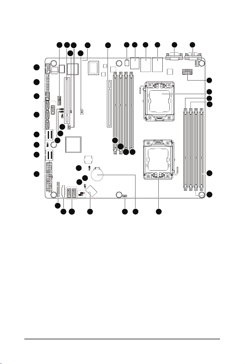
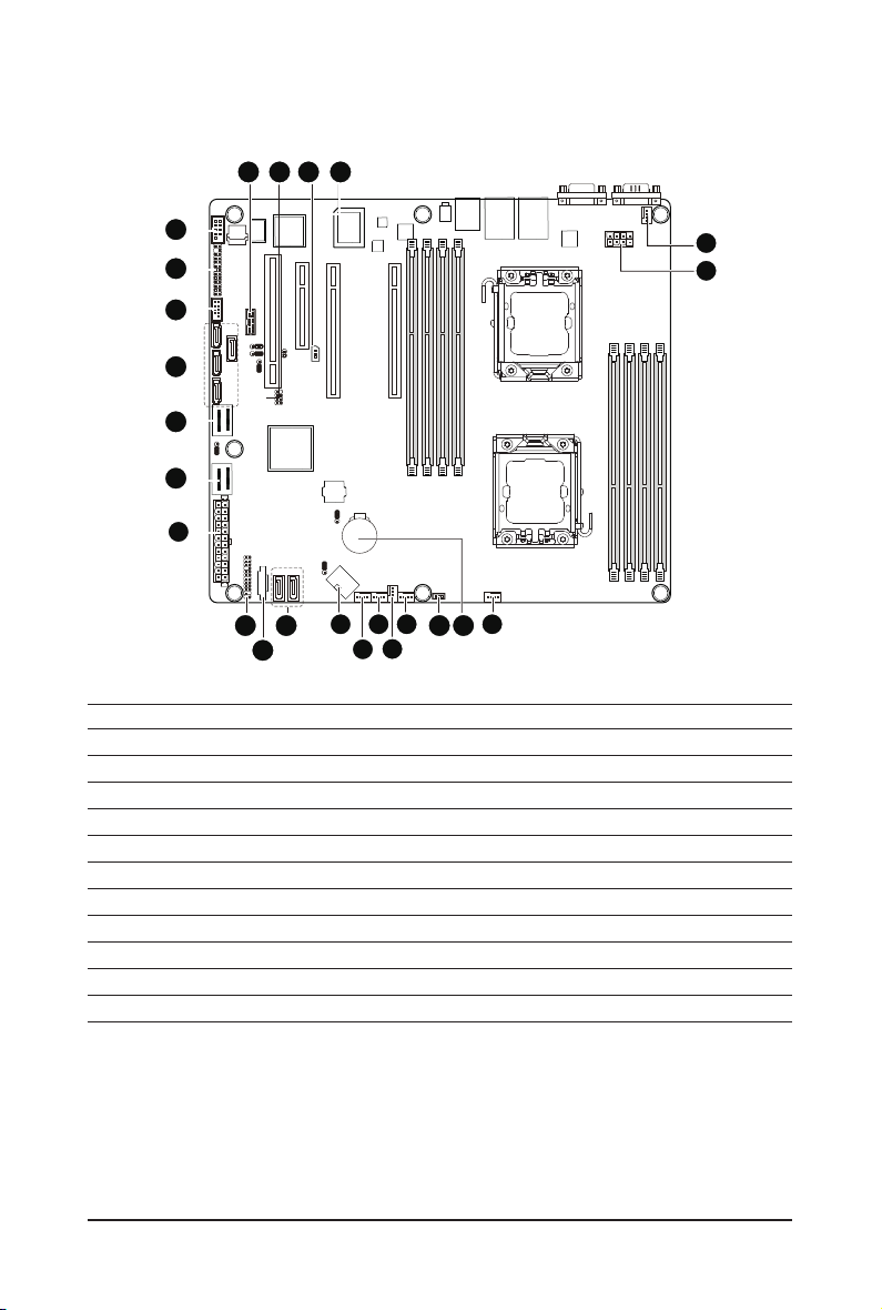
GA-7PCSL Motherboard Layout
27
26
25
24
23
22
21
20
28 29
41
40
39
19
30
31
42
44
32
43
33
34
1 2 3 4 6
35
36
37 38
131415161718
5
7
8
9
10
11
12
- 6 -

Item Code Description
1 ID_SW ID switch
2 MLAN BMC Management LAN port
3 USB_LANB1 LAN1 port (top) / USB ports (bottom)
4 USB_LANB2 LAN2 port (top) / USB ports (bottom)
5 VGA_1 VGA port
6 COM1 Serial port
7 CPU1_FAN CPU1 fan cable connector
8 P12V_AUX2 8 pin power connector
9 CPU1 Intel LGA1356 socket (Secondary CPU)
10 DDR3_P0_C1 Channel C slot 1 (for primary CPU)
11 DDR3_P0_C0 Channel C slot 0 (for primary CPU)
12 DDR3_P0_A0 Channel A slot 0 (for primary CPU)
13 DDR3_P0_B0 Channel B slot 0 (for primary CPU)
14 CPU0 Intel LGA1356 socket (Primary CPU)
15 CPU0_FAN CPU0 fan connector
16 BAT CMOS battery
17 SKU_KEY1 PBG A SKU Select connector
18 SYS_FAN4 System fan connector
19 SYS_FAN3 System fan connector
20 SYS_FAN2 System fan connector
21 SYS_FAN1 System fan connector
22 P12V_AUX1 8 pin power connector
23 SATA0/1 SATA 6Gb/s connectors
24 PMbus_CN_1 PM Bus connector
25 BP_1 HDD back plane connector
26 ATX1 24-pin power connector
27 MINISAS_2 Mini SAS connector (SATA 3.0Gb/s signal)
28 SSB_ME2 ME enable/disable jumper
29 MINISAS_1 Mini SAS connector
30 SAS0~3 SAS connectors
31 F_USB1 Front USB connector
32 FP_1 Front panel connector
33 COM2 Serial cable connector
34 TPM_MEZZ1 TPM connector
35 PCI_1 PCI slot (32bit/33MHz)
36 JP5 Chassis intrusion jumper
37 SCU_SGPIO SCU SGPIO connector
38 PCIE_3 PCI-E slot 3 (x8 slot / x4 signal)
39 IPMB IPMB connector
40 BMC_LED1 BMC Firmware Readiness LED
41 PCIE_2 PCI-E slot 2 (x16 slot / x8 signal)
42 PCIE_1 PCI-E slot 1 (x16 slot)
43 DDR3_P1_D0 Channel A slot 0 (for secondary CPU)
44 DDR3_P1_E0 Channel B slot 0 (for secondary CPU)
45 DDR3_P1_F0 Channel C slot 0 (for secondary CPU)
- 7 -

46 DDR3_P1_F1 Channel C slot 1 (for secondary CPU)
47 PASSWORD Clear password jumper
48 BIOS_RVCR BIOS recovery jumper
49 SSB_ME1 ME enable/disable jumper
50 CLR_CMOS Clear CMOS jumper
51 BIOS_WP BIOS write protect jumper
52 SATA_DOM0/SATA_DOM1 SATA0/1 port DOM support jumper
- 8 -
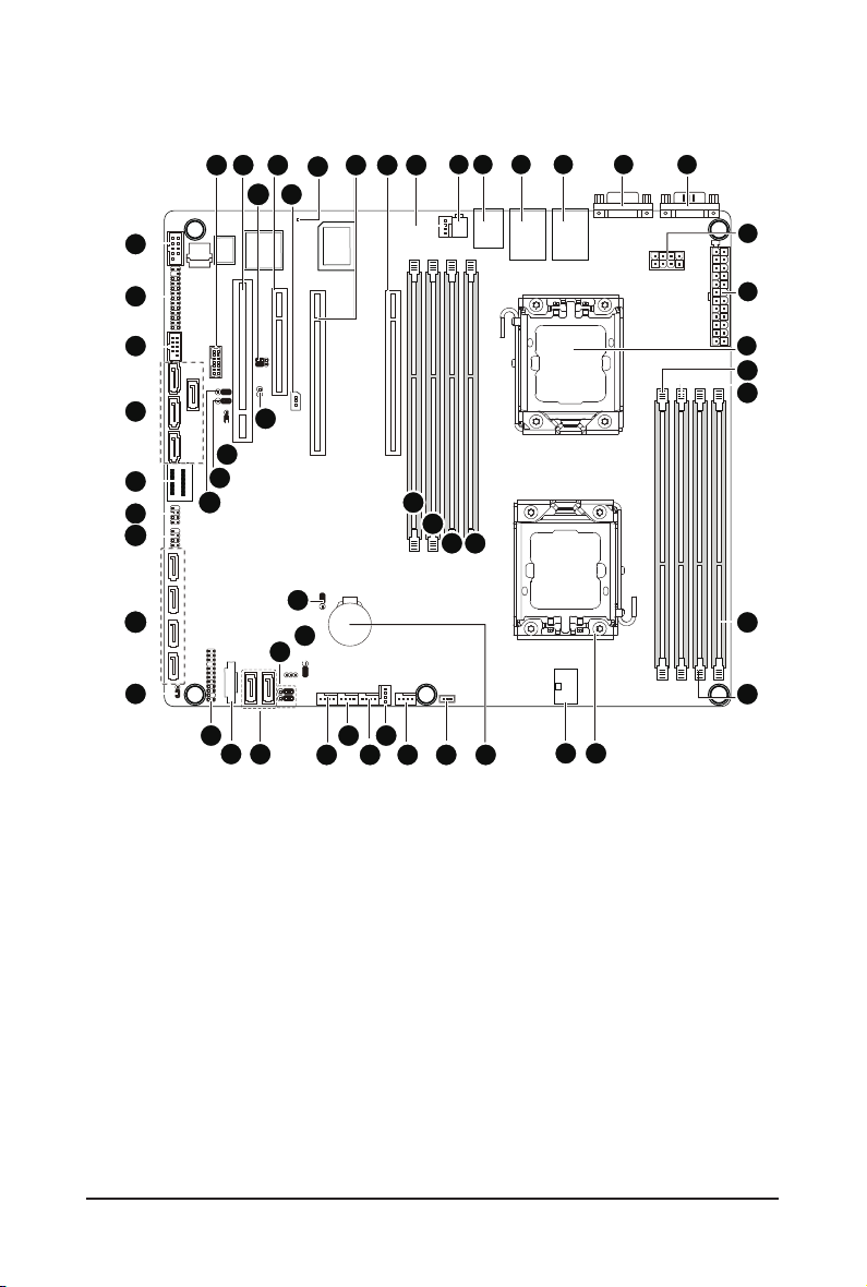
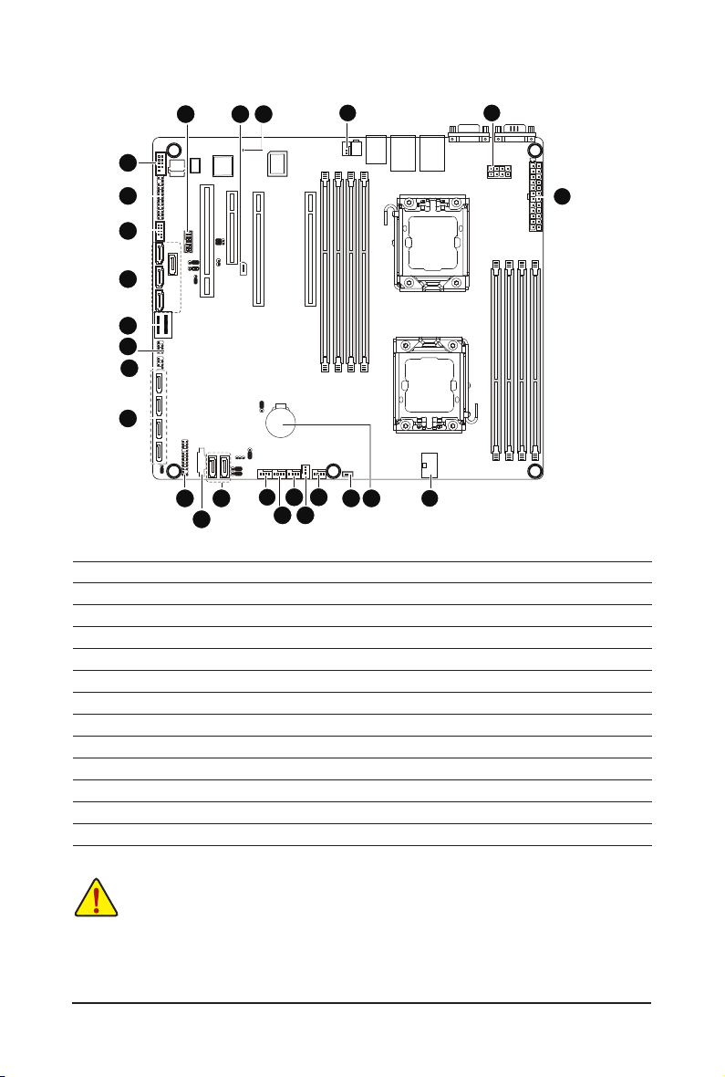
GA-7PCSLX Motherboard Layout
34
33
32
31
30
29
28
27
26
35 36
50
49
48
25
24
37
23
51
38
54
39
52
53
40
22
21
41
20
19
42
43
1 2 3 4 6
44
45
46 47
161718
5
7
8
9
10
11
12
13
1415
- 9 -

Item Code Description
1 ID_SW ID switch
2 MLAN BMC Management LAN port
3 USB_LANB1 LAN1 port (top) / USB ports (bottom)
4 USB_LANB2 LAN2 port (top) / USB ports (bottom)
5 VGA_1 VGA port
6 COM1 Serial port
7 P12V_AUX2 8 pin power connector
8 ATX1 24-pin power connector
9 CPU1 Intel LGA1356 socket (Secondary CPU)
10 DDR3_P0_C1 Channel C slot 1 (for primary CPU)
11 DDR3_P0_C0 Channel C slot 0 (for primary CPU)
12 DDR3_P0_A0 Channel A slot 0 (for primary CPU)
13 DDR3_P0_B0 Channel B slot 0 (for primary CPU)
14 CPU0 Intel LGA1356 socket (Primary CPU)
15 P12V_AUX1 8 pin power connector
16 BAT CMOS battery
17 SKU_KEY1 PBG A SKU Select connector
18 CPU0_FAN CPU0 fan connector
19 SYS_FAN4 System fan connector
20 SYS_FAN3 System fan connector
21 SYS_FAN2 System fan connector
22 SYS_FAN1 System fan connector
23 SATA0/1 SATA 6Gb/s connectors
24 PMbus_CN_1 PM Bus connector
25 BP_1 HDD back plane connector
26 SSB_ME2 ME enable/disable jumper
27 SATA2/3/4/5 SATA 3Gb/s connectors
28 SATA_SGPIO SATA SGPIO coneector
29 SCU_SGPIO SCU SGPIO connector
30 MINISAS_1 Mini SAS connector
31 SAS0~3 SAS connectors
32 F_USB1 Front USB connector
33 FP_1 Front panel connector
34 COM2 Serial cable connector
35 TPM_MEZZ1 TPM connector
36 PCI_1 PCI slot (32bit/33MHz)
37 ROMST_FRB3 Force to Stop FRB3 Timer jumper
38 PCIE_3 PCI-E slot 3 (x8 slot / x4 signal)
39 IPMB IPMB connector
40 BMC_LED1 BMC Firmware Readiness LED
41 PCIE_2 PCI-E slot 2 (x16 slot / x8 signal)
42 PCIE_1 PCI-E slot 1 (x16 slot)
43 CPU1_FAN CPU1 fan connector
44 DDR3_P1_D0 Channel A slot 0 (for secondary CPU)
45 DDR3_P1_E0 Channel B slot 0 (for secondary CPU)
- 10 -

46 DDR3_P1_F0 Channel C slot 0 (for secondary CPU)
47 DDR3_P1_F1 Channel C slot 1 (for secondary CPU)
48 PASSWORD Clear password jumper
49 BIOS_RCVR BIOS recovery jumper
50 SSB_ME1 ME enable/disable jumper
51 JP5 Chassis intrusion jumper
52 CLR_CMOS Clear CMOS jumper
53 BIOS_WP BIOS write protect jumper
54 SATA_DOM0/SATA_DOM1 SATA0/1 port DOM support jumper
CAUTION! If a SATA type hard drive is connected to the motherboard, please ensure the jumper is
closed and set to 2-3 pins (Normal mode), in order to reduce any risk of hard disk damage. Please
refer to Page 49 for SATA_DOM0 and SATA_DOM1 jumper setting instruction.
- 11 -

Chapter 1 Hardware Installation
1-1 Installation Precautions
The motherboard contains numerous delicate electronic circuits and components which can
become damaged as a result of electrostatic discharge (ESD). Prior to installation, carefully read
the user's manual and follow these procedures:
• Prior to installation, do not remove or break motherboard S/N (Serial Number) sticker or
warranty sticker provided by your dealer. These stickers are required for warranty validation.
• Always remove the AC power by unplugging the power cord from the power outlet before
installing or removing the motherboard or other hardware components.
• When connecting hardware components to the internal connectors on the motherboard,
make sure they are connected tightly and securely.
• When handling the motherboard, avoid touching any metal leads or connectors.
• It is best to wear an electrostatic discharge (ESD) wrist strap when handling electronic com-
ponents such as a motherboard, CPU or memory. If you do not have an ESD wrist strap,
keep your hands dry and rst touch a metal object to eliminate static electricity.
• Prior to installing the motherboard, please have it on top of an antistatic pad or within an
electrostatic shielding container.
• Before unplugging the power supply cable from the motherboard, make sure the power sup-
ply has been turned off.
• Before turning on the power, make sure the power supply voltage has been set according to
the local voltage standard.
• Before using the product, please verify that all cables and power connectors of your hard-
ware components are connected.
• To prevent damage to the motherboard, do not allow screws to come in contact with the
motherboard circuit or its components.
• Make sure there are no leftover screws or metal components placed on the motherboard or
within the computer casing.
• Do not place the computer system on an uneven surface
• Do not place the computer system in a high-temperature environment.
• Turning on the computer power during the installation process can lead to damage to sys-
tem components as well as physical harm to the user.
• If you are uncertain about any installation steps or have a problem related to the use of the
product, please consult a certied computer technician.
.
Hardware Installation - 12 -
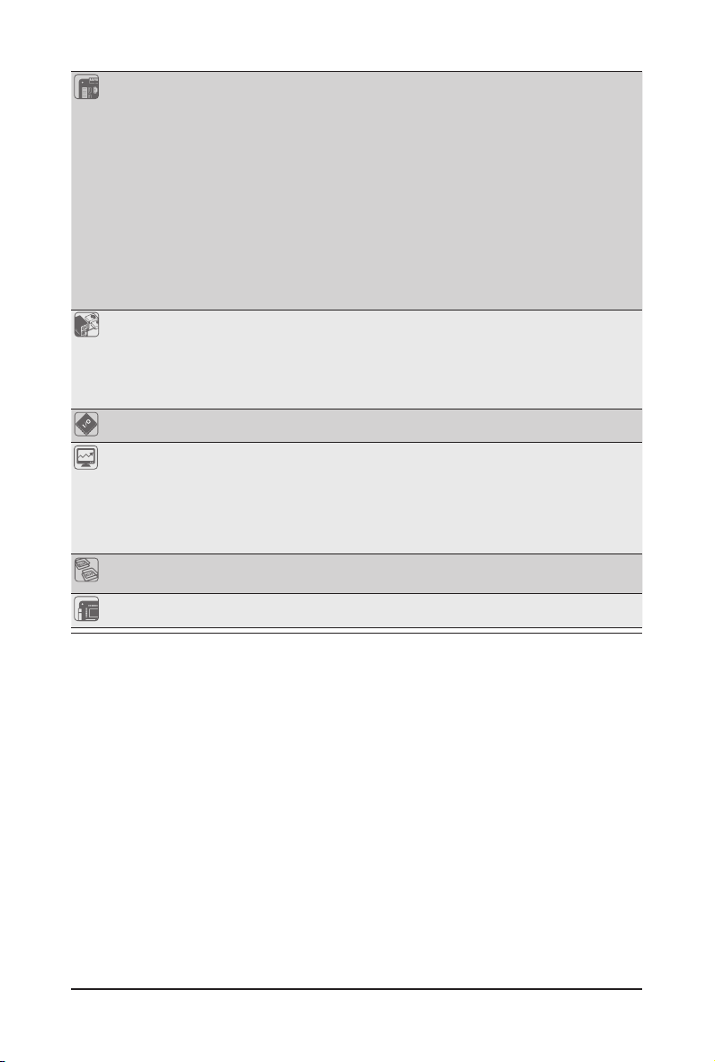
1-2 ProductSpecications
GA-7PCSL
CPU Support for Dual Intel® Xeon® Sandy-bridge-EN 2S processors in 1356 socket
Intel® Xeon® Quad Core in LGA 1356 socket
Supports QuickPath Interconnect up to 8GT/s
Enhanced Intel SpeedStep Technology (EIST) & Demand BasedSwitch (DBS)
Enhanced Intel SpeedStep Technology (EIST)
Support Intel Virtualization Technology (VT)
Chipset Intel® C600 (Patsburg) Chipset
Memory 8 x 1.5V DDR3 DIMM sockets supporting up to 64 GB of systemmemory
LAN 2 x Intel® 82574L supports 10/100/1000 Mbps
Expansion Slots 1 x PCI Express x16 slot, running at x16 (PCIE_1)
Onboard
Graphics
Storage Interface Intel® C600 controller
USB Up to 6 US B 2.0/1.1 ports (4 on the bac k panel, 2 via the USB bra ckets connected
* Due to Windows 32-bit operating system limitation, when more than 4 GB of physical
memory is installed, the actual memory size displayed will be less than 4 GB.
8 x 1.35V DDR3L DIMM sockets supporting up to 32 GB of system memory
3 channel memory architecture
Support for 800/1066/1333/1600 memory modules
Support for ECC RDIMM/ UDIMM memory modules
1 x PCI Express x8 slot, running at x8 (PCIE_2)
1 x PCI Express x8 slot, running at x4 (PCIE_ 3)
1 x PCI slot 32-Bit/33MHz (PCI_1)
ASPEED® AST2300 supports 16MB VR AM
4 x SATA 3Gb/s connectors (SAS0/1/2/3/via SCU)
1 x mini SAS connectors (4 SATA ports (3Gb/s)/optional with Upgrade ROM
attached)
1 x mini SAS connector (4 SATA ports (3Gb/s)
2 x SATA 6Gb/s connectors (SATA0/1)
Support for Intel RSTe SATA RAID 0, R AID 1
to the internal USB headers)
- 13 - Hardware Installation
Internal
Connectors
1 x 24-pin ATX main power connector
2 x 8-pin ATX 12V power connector
4 x SATA 3Gb/s connectors (SAS0~3)
2 x mini SAS 3Gb/s connectors
2 x SATA 6Gb/s connectors
1 x PSMI header
2 x CPU fan header
4 x System fan header
1 x Front panel header
2 x USB 2.0/1.1 headers
1 x Serial port header
1 x SPGIO header
Rear Panel I/O 4 x USB 2.0/1.1 ports
2 x RJ-45 port
1 x COM port
1 x VGA port
1 x ID Switch button
I/O Controller ASPEED® AST2300 BMC chip
Hardware
Monitor
System voltage detection
CPU/System temperature detection
CPU/System fan speed detection
CPU/System fan speed control
* Whether the CPU/system fan speed control function is supported will depend on
the CPU/system cooler you install.
BIOS 1 x 64 Mbit ash
AMI BIOS
Form Factor CEB Form Factor; 12 inch x 10.5 inch, 6 layers PCB
* GIGA BYTE reserves the right to make any changes to the product specications and product-related information
without prior notice.
Hardware Installation - 14 -
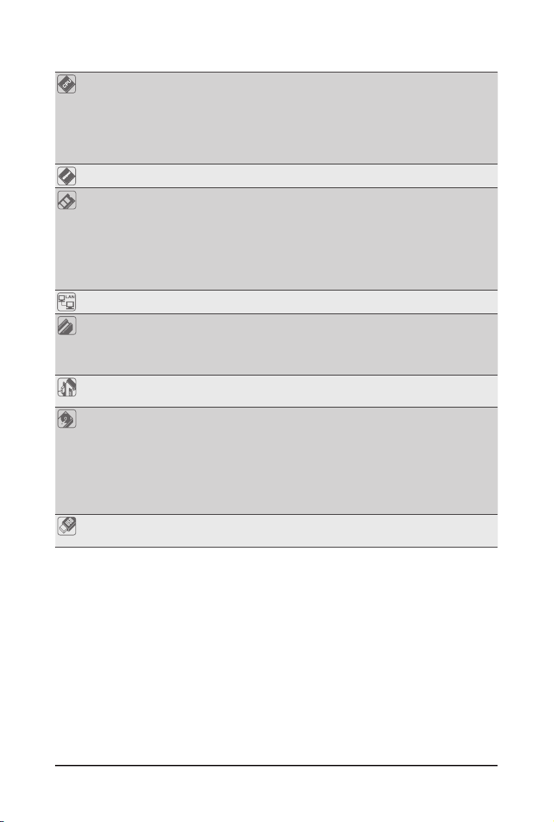
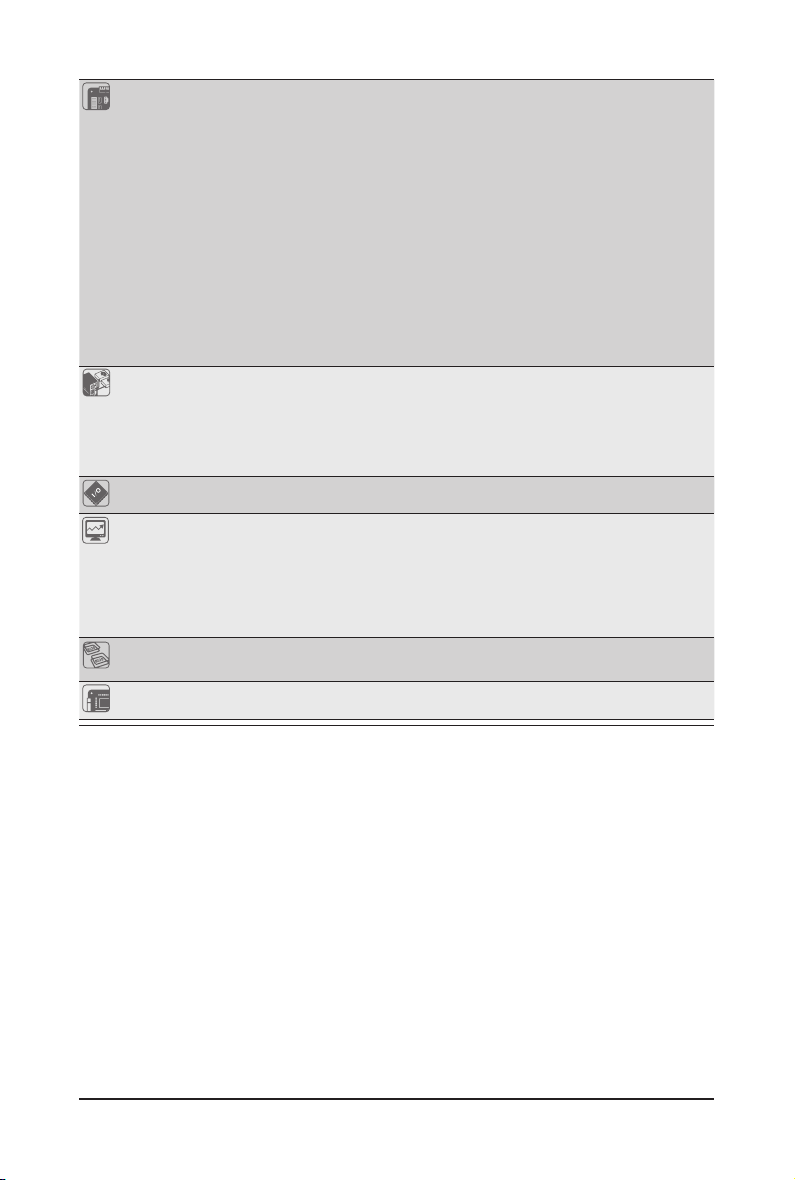
GA-7PCSLX
CPU Support for Dual Intel® Xeon® Sandy-bridge-EN 2S processors in 1356 socket
Intel® Xeon® Quad Core in LGA 1356 socket
Suppor ts QuickPath Interconnect up to 8GT/s
Enhanced Intel SpeedStep Technology (EIST) & Demand BasedSwitch (DBS)
Enhanced Intel SpeedStep Technology (EIST)
Support Intel Virtualization Technology (VT)
Chipset Intel® C600 (Patsburg) Chipset
Memory 8 x 1.5V DDR3 DIMM sockets supporting up to 64 GB of systemmemory
LAN 2 x Intel® 82574L supports 10/100/1000 Mbps
Expansion Slots 1 x PCI Express x16 slot, running at x16 (PCIE_1)
Onboard
Graphics
Storage Interface Intel® C600 controller
USB Up to 6 US B 2.0/1.1 po rts (4 on the back panel, 2 v ia the USB brackets co nnected
* Due to Windows 32-bit operating system limitation, when more than 4 GB of physical
memory is installed, the actual memory size displayed will be less than 4 GB.
8 x 1.35V DDR3L DIMM sockets supporting up to 32 GB of system memory
3 channel memory architecture
Support for 800/1066/1333/1600 memory modules
Support for ECC RDIMM/ UDIMM memory modules
1 x PCI Express x8 slot, running at x8 (PCIE_2)
1 x PCI Express x8 slot, running at x4 (PCIE_3)
1 x PCI slot 32-Bit/33MHz (PCI_1)
ASPEED® AST2300 supports 16MB VR AM
4 x SATA 3Gb/s connectors (SAS0/1/2/3/via SCU)
1 x mini SAS connector (4 SATA ports (3Gb/s)/optional with Upgrade ROM
attached)
4 x SATA 3Gb/s connectors (SATA2/3/4/5)
2 x SATA 6Gb/s connectors (SATA0/1)
Support for Intel RSTe SATA RAID 0, R AID 1
to the internal USB headers)
Hardware Installation - 15 -
Internal
Connectors
1 x 24-pin ATX main power connector
2 x 8-pin ATX 12V power connector
4 x SATA 3Gb/s connectors (SAS0/1/2/3)
1 x mini SAS 3Gb/s connector
4 x SATA 3Gb/s connectors (SATA2/3/4/5)
2 x SATA 6Gb/s connectors
1 x PSMI header
2 x CPU fan header
4 x System fan header
1 x Front panel header
2 x USB 2.0/1.1 headers
1 x Serial port header
1 x SPGIO header
Rear Panel I/O 4 x USB 2.0/1.1 ports
2 x RJ-45 port
1 x COM port
1 x VGA port
1 x ID Switch button
I/O Controller ASPEED® AST2300 BMC chip
Hardware
Monitor
System voltage detection
CPU/System temperature detection
CPU/System fan speed detection
CPU/System fan speed control
* Whether the CPU/system fan speed control function is supported will depend on
the CPU/system cooler you install.
BIOS 1 x 64 Mbit ash
AMI BIOS
Form Factor CEB Form Factor; 12 inch x 10.5 inch, 8 layers PCB
* GIGA BYTE reserves the right to make any changes to the product specications and product-related information
without prior notice.
Hardware Installation - 16 -
1-3 Installing the CPU and CPU Cooler
Read the following guidelines before you begin to install the CPU:
• Make sure that the motherboard supports the CPU.
(Go to GIGABYTE's website for the latest CPU support list.)
• Always turn off the computer and unplug the power cord from the power outlet before installing
the CPU to prevent hardware damage.
• Locate the pin one of the CPU. The CPU cannot be inserted if oriented incorrectly. (Or you may
locate the notches on both sides of the CPU and alignment keys on the CPU socket.)
• Apply an even and thin layer of thermal grease on the surface of the CPU.
• Do not turn on the computer if the CPU cooler is not installed, otherwise overheating and
damage of the CPU may occur.
• Set the CPU host frequency in accordance with the CPU specications. It is not recommended
that the system bus frequency be set beyond hardware specications since it does not meet the
standard requirements for the peripherals. If you wish to set the frequency beyond the standard
specifications, please do so according to your hardware specifications including the CPU,
graphics card, memory, hard drive, etc.
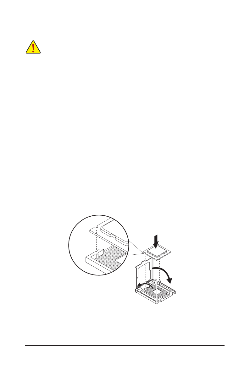
1-3-1 Installing the CPU
Step 1. Raise the metal locking lever on the socket.
Step 2. Remove the plastic covering on the CPU socket.
Step 3. Lift the metal cover.
Step 4. Insert the CPU with the correct orientation. The CPU only ts in one orientation.
Step 5. Please replace the metal cover and push the metallever back into locked position.
- 17 - Hardware Installation
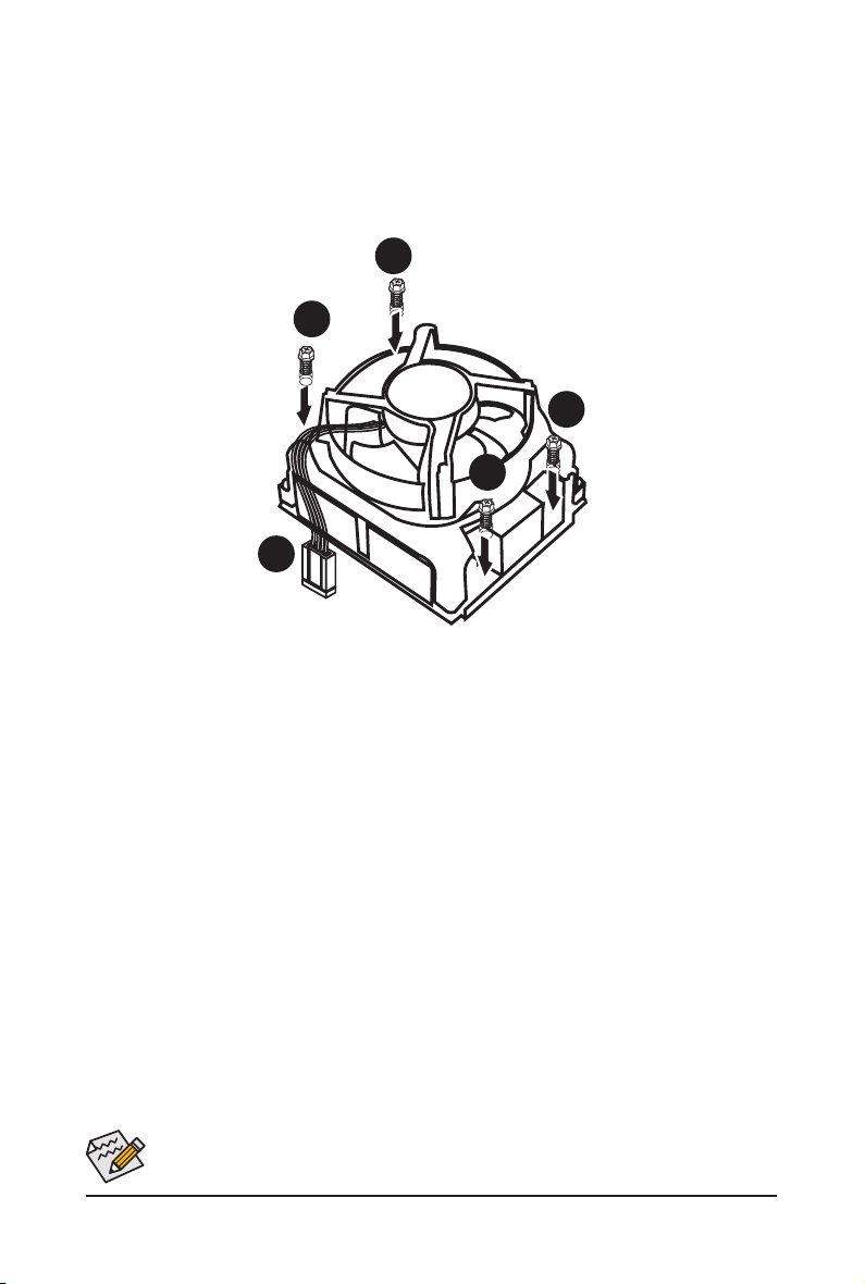
1-3-2 Installing the CPU Cooler
Follow the steps below to correctly install the CPU cooler on the motherboard.
Step 1. Attach the heat sink clip to the processor socket.
Step 2. Secure the cooing fan with screws..
Step 3. Connect processor fan can cable to the processor fan connector.
1
1
1
1
2
Use extreme care when removing the CPU cooler because the thermal grease/tape between the
CPU cooler and CPU may adhere to the CPU. Inadequately removing the CPU cooler may damage
the CPU.
Hardware Installation - 18 -
1-4 Installing the Memory
Read the following guidelines before you begin to install the memory:
• Make sure that the motherboard supports the memory. It is recommended that memory of the
same capacity, brand, speed, and chips be used.
(
Go to GIGABYTE's website for the latest supported memory speeds and memory modules.
• Always turn off the computer and unplug the power cord from the power outlet before installing
the memory to prevent hardware damage.
• Memory modules have a foolproof design. A memory module can be installed in only one
direction. If you are unable to insert the memory, switch the direction.
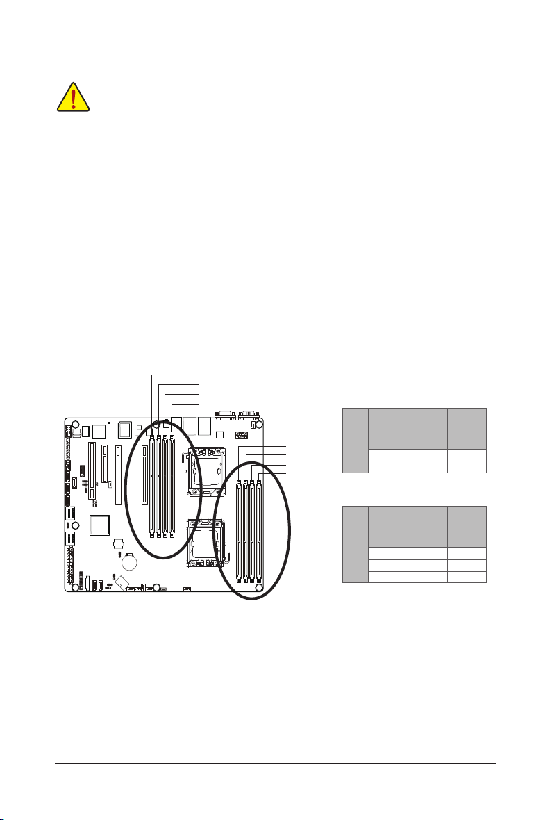
1-4-1 Dual/3ChannelMemoryConguration
This motherboard provides eight DDR3 memory sockets and supports Dual/3 Channel Technology. After the
memory is installed, the BIOS will automatically detect the specications and capacity of the memory. Enabling Dual Channel memory mode will double the original memory bandwidth.
The four DDR3 memory sockets are divided into two channels and each channel has two memory sockets as
following:
Channel A: DDR3_P0_A0, DDR3_P1_D0
Channel B: DDR3_P0_B0, DDR3_P1_E0
Channel C: DDR3_P0_C0, DDR3_P0_C1, DDR3_P1_F0,DDR3_P1_F1
DDR3_P1_D0
DDR3_P1_E0
DDR3_P1_F0
DDR3_P1_F1
DDR3_P0_C1
DDR3_P0_C0
DDR3_P0_B0
DDR3_P0_A0
U-DIMM
DDR3_P0_A0
DDR3_P1_D0
Channel B Channel C
Channel A
DDR3_P0_B0
DDR3_P1_E0
Single-Rank Single-Rank Single-Rank
Dual-Rank Dual-Rank Dual-Rank
DDR3_P0_C0
DDR3_P0_C1
DDR3_P1_F0
DDR3_P1_F1
)
GA-7PCSL
Channel A
Channel B Channel C
DDR3_P0_B0
DDR3_P1_E0
Single-Rank Single-Rank Single-Rank
Dual-Rank Dual-Rank Dual-Rank
Quad-Rank Quad-Rank Quad-Rank
R-DIMM
DDR3_P0_A0
DDR3_P1_D0
DDR3_P0_C0
DDR3_P0_C1
DDR3_P1_F0
DDR3_P1_F1
Due to CPU limitation, read the following guidelines before installing the memory in Dual or 3 Channel mode
Dual Channel--
1. Dual Channel mode cannot be enabled if only one DDR3 memory module is installed.
2. When enabling Dual Channel mode with two or four modules, it is recommended that memory of th
same capacity, brand, speed, and chips be used. When enabling Dual Channel mode with two
memory modules, be sure to install them in the DDR3_P0_C0 and DDR3_P0_C1 sockets for primary
CPU; install DDR3_P1_F0 and DDR3_P1_F1 for secondary CPU.
3 Channel--
1. 3 Channel mode cannot be enabled if only one or two DDR3 memory modules are installed.
2. When enabling 3 Channel mode with three, four or six modules, it is recommended that memory of
the same capacity, brand, speed, and chips be used. When enabling 3 Channel mode with three
- 19 - Hardware Installation
memory modules, be sure to install them in the DDR3_P0_A0, DDR3_P0_B0 and DDR3_P0_C0
sockets for primary CPU; install DDR3_P1_D0, DDR3_P1_E0 DDR3_P1_F0 for secondary CPU.
When enabling 3 Channel mode with four memory modules, be sure to install them in the
DDR3_P0_A0, DDR3_P0_B0, DDR3_P0_C0, and and DDR3_P0_C1 sockets for primary CPU; install
DDR3_P1_D0, DDR3_P1_E0, DDR3_P1_F0, and DDR3_P1_F1 for secondary CPU
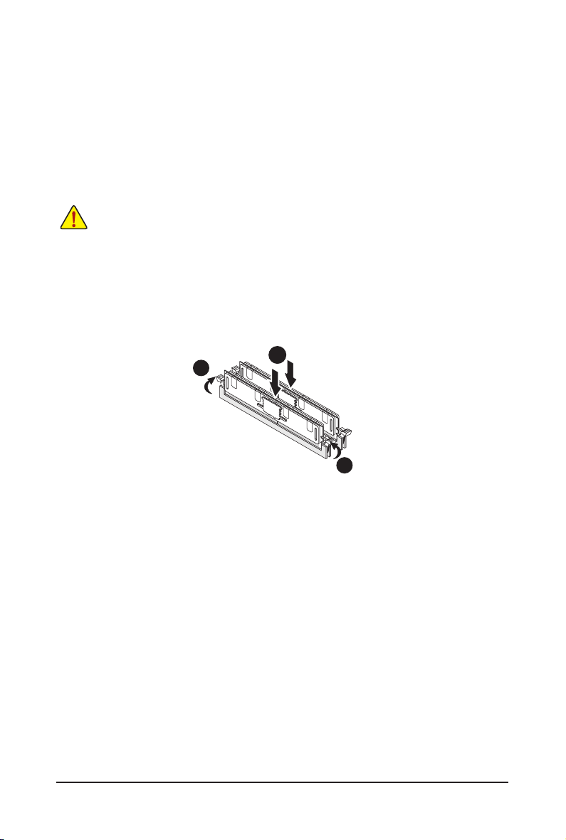
1-4-2 Installing a Memory
Before installing a memory module, make sure to turn off the computer and unplug the power
cord from the power outlet to prevent damage to the memory module.
Be sure to install DDR3 DIMMs on this motherboard.
Installation Step:
Step 1. Insert the DIMM memory module vertically into the DIMM slot, and push it down.
Step 2. Close the plastic clip at both edges of the DIMM slots to lock the DIMM module.
Note: For dual-channel operation, DIMMs must be installed in matched pairs.
Step 3. Reverse the installation steps when you wish to remove the DIMM module.
2
1
2
Hardware Installation - 20 -
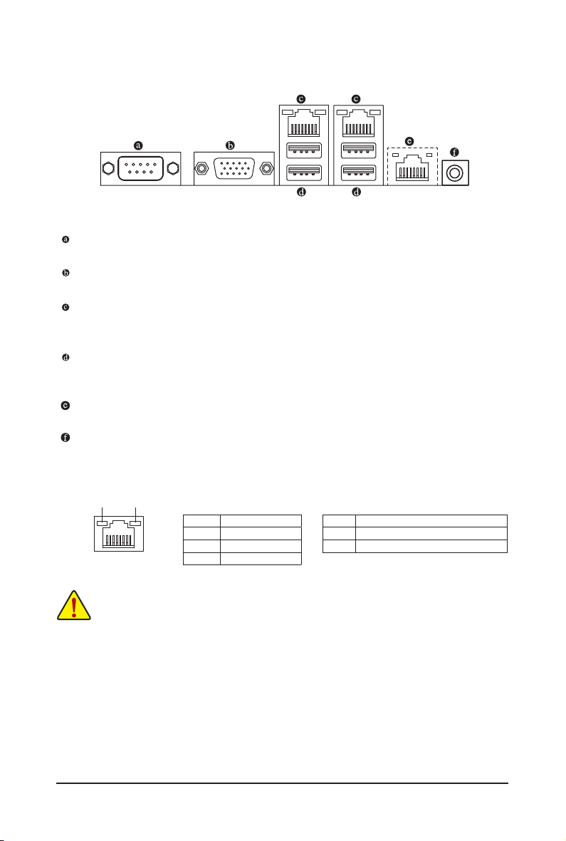
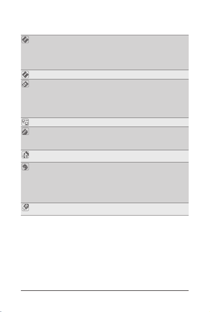
1-5 Back Panel Connectors
Serial Port
Connects to serial-based mouse or data processing devices.
Video Port
The video in port allows connect to video in, which can also apply to video loop thru function.
RJ-45 LAN Port
The Gigabit Ethernet LAN port provides Internet connection at up to 1 Gbps data rate. The following
describes the states of the LAN port LEDs.
USB 2.0/1.1 Port
The USB port supports the USB 2.0/1.1 specication. Use this port for USB devices such as a USB keyboard/mouse, USB printer, USB ash drive and etc.
KVM Server Management 10/100 LAN Port
The LAN port provides Internet connection with data transfer speeds of 10/100Mbps.
ID Switch Button
This button provide the selected unit idencation function.
Connection/
Speed LED
LAN Port
Activity LED
State Description
Orange 1 Gb ps data rate
Green 100 Mbps data rate
Off 10 Mbps data rate
Activity LED:Connection/Speed LED:
State Description
Blinking Data transmission or receiving is occurring
On No data tr ansmission
• When removing the cable connected to a back panel connector, rst remove the cable from your
device and then remove it from the motherboard.
• When removing the cable, pull it straight out from the connector. Do not rock it side to side to
prevent an electrical short inside the cable connector.
- 21 - Hardware Installation
1-6 Internal Connectors
GA-7PCSL
14
19
21
24
13
15
12
18
16
17
1
22
11
2
10
1) ATX1
2) P12V_AUX1
3) P12V_AUX2
4) CPU0_FAN (for primary CPU)
5) CPU1_FAN (for seconary CPU)
6) SYS_FAN4 (System Fan)
7) SYS_FAN3 (System Fan)
8) SYS_FAN2 (System Fan)
9) SYS_FAN1 (System Fan)
10) PMbus_CN_1
11) SATA0/1
12) F_USB1
5
3
20
23
678
9
4
13) COM2
14) SCU_SGPIO
15) FP_1
16) MINISAS_1
17) MINISAS_2
18) SAS0/1/2/3
19) IPMB
20) BAT
21) TPM_MEZZ1
22) BP_1
23) SKU_KEY1
24) BMC_LED1
Hardware Installation - 22 -
GA-7PCSLX
13
21
19
24
35
15
12
18
16
14
25
17
22
11
9
10
1) ATX1
2) P12V_AUX1
3) P12V_AUX2
4) CPU0_FAN (for primary CPU)
5) CPU1_FAN (for seconary CPU)
6) SYS_FAN4 (System Fan)
7) SYS_FAN3 (System Fan)
8) SYS_FAN2 (System Fan)
9) SYS_FAN1 (System Fan)
10) PMbus_CN_1
11) SATA0/1
12) F_USB1
13) COM2
8
20
23
467
14) SCU_SGPIO
15) FP_1
16) MINISAS_1
17) SATA2/3/4/5
18) SAS0/1/2/3
19) IPMB
20) BAT
21) TPM_MEZZ1
22) BP_1
23) SKU_KEY1
24) BMC_LED1
25) SATA_SGPIO
1
2
Read the following guidelines before connecting external devices:
• First make sure your devices are compliant with the connectors you wish to connect.
• Before installing the devices, be sure to turn off the devices and your computer. Unplug the
power cord from the power outlet to prevent damage to the devices.
• After installing the device and before turning on the computer, make sure the device cable has
been securely attached to the connector on the motherboard.
Hardware Installation - 23 -
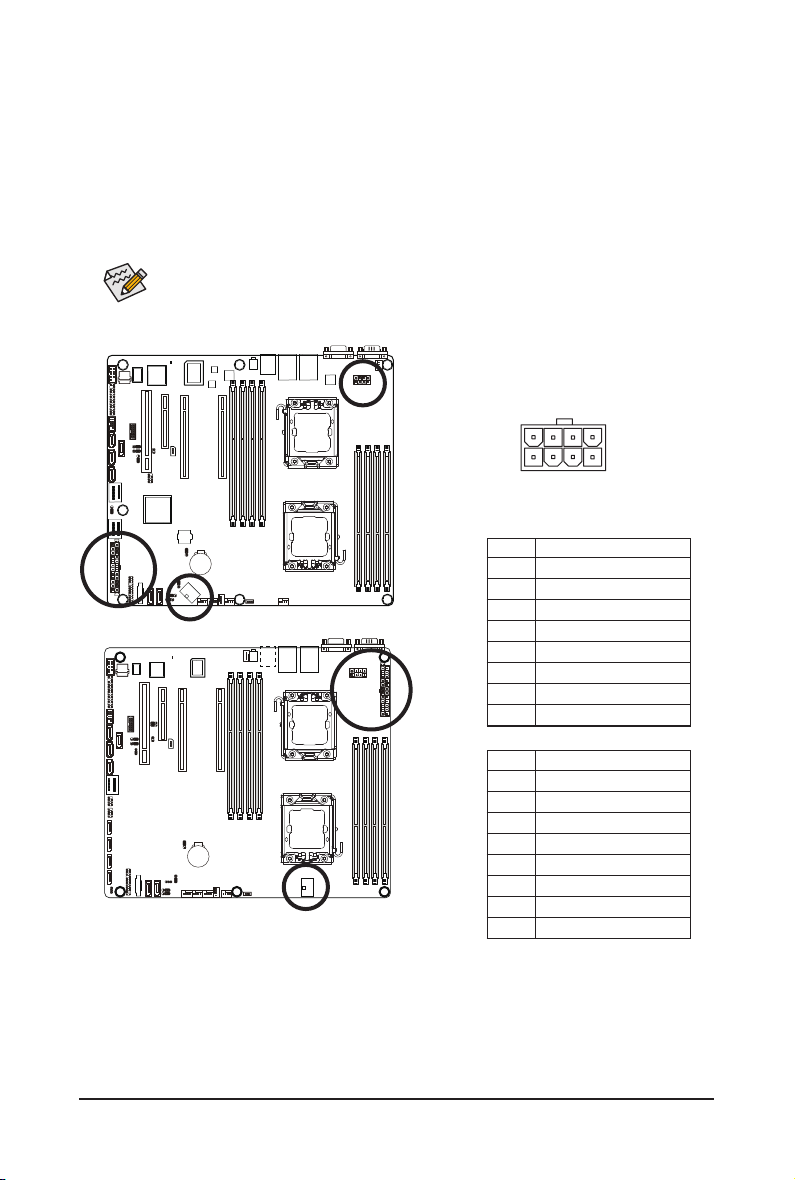
1/2/3) ATX1/P12V_AUX1/P12V_AUX2
(2x4 12V Power Connector and 2x12 Main Power Connector)
With the use of the power connector, the power supply can supply enough stable power to all the com-
ponents on the motherboard. Before connecting the power connector, rst make sure the power supply
is turned off and all devices are properly installed. The power connector possesses a foolproof design.
Connect the power supply cable to the power connector in the correct orientation. The 12V power connector mainly supplies power to the CPU. If the 12V power connector is not connected, the computer will
not start.
To meet expansion requirements, it is recommended that a power supply that can withstand high
power consumption be used (500W or greater). If a power supply is used that does not provide
the required power, the result can lead to an unstable or unbootable system.
P12V_AUX1
P12V_AUX2
85
GA-7PCSL
GA-7PCSLX
GA-7PCSLN
41
P12V_AUX1
Pin No. Denition
1 GND
2 GND
3 GND
4 GND
5 P12V_DDR3_CPU0
6 P12V_DDR3_CPU0
7 P12V_CPU0
8 P12V_CPU0
P12V_AUX2
Pin No. Denition
1 GND
2 GND
3 GND
4 GND
5 P12V_DDR3_CPU1
6 P12V_DDR3_CPU1
7 P12V_CPU1
8 P12V_CPU1
- 24 - Hardware Installation
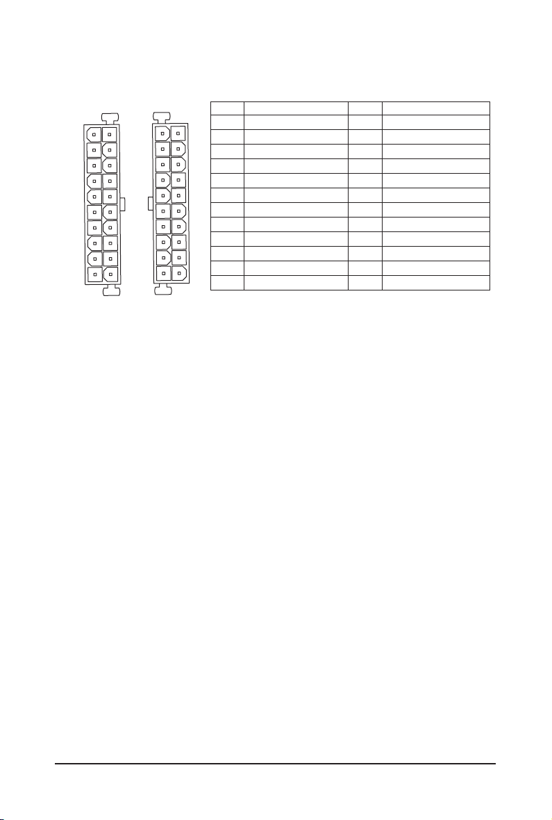
ATX1
ATX
(GA-7PCSL)
12
1
ATX1
(GA-7PCSLX)
24
13
13
24
ATX1
1
Pin No. Denition
1 3.3V
2 3.3V
3 GND
4 +5V
5 GND
6 +5V
7 GND
8 Power Good
9 5VSB (stand by +5V)
10 +12V
11 +12V (Only for 2x12-pin ATX)
12 3.3V (Only for 2x12-pin ATX)
12
Pin No. Denition
13 3.3V
14 -12V
15 GND
16 PS_ON (soft On/Off)
17 GND
18 GND
19 GND
20 -5V
21 +5V
22 +5V
23 +5V (Only for 2x12-pin ATX)
24 GND (Only for 2x12-pin ATX)
- 25 - Hardware Installation
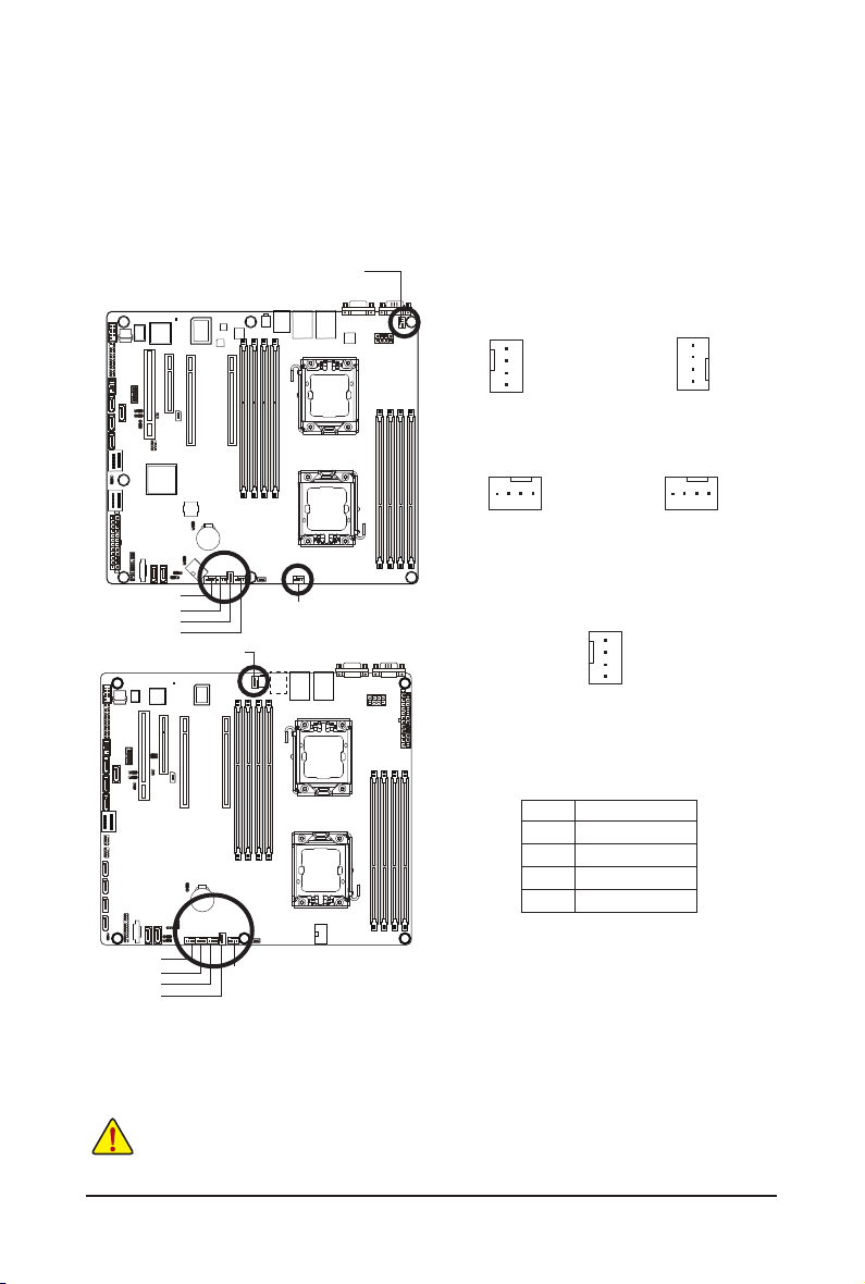
4/5/6/7/8/9) CPU0_FAN/CPU1_FAN/SYS_FAN4/SYS_FAN3/SYS_FAN2/SYS_FAN1
(CPU Fan/System Fan Headers)
The motherboard has a 4-pin CPU fan header (CPU_FAN1/2), a 4-pin (FAN4) system fan headers. Most
fan headers possess a foolproof insertion design. When connecting a fan cable, be sure to connect it in
the correct orientation (the black connector wire is the ground wire). The motherboard supports CPU fan
speed control, which requires the use of a CPU fan with fan speed control design. For optimum heat dissipation, it is recommended that a system fan be installed inside the chassis.
CPU1_FAN
1
1
CPU1_FAN
(GA-7PCSLX)
GA-7PCSL
CPU1_FAN
SYS_FAN3
(GA-7PCSL)
1
CPU0_FAN
SYS_FAN1
SYS_FAN2
SYS_FAN4
SYS_FAN1
SYS_FAN2
SYS_FAN3
SYS_FAN4
CPU1_FAN
CPU0_FAN
GA-7PCSLX
GA-7PCSLN
(GA-7PCSL)
Pin No. Denition
1 GND
SYS_FAN4
(GA-7PCSLX)
1
2 +12V
3 Sense
4 Speed Control
SYS_FAN1
SYS_FAN2
SYS_FAN3
SYS_FAN4
CPU0_FAN
• Be sure to connect fan cables to the fan headers to prevent your CPU and system from
overheating. Overheating may result in damage to the CPU or the system may hang.
• These fan headers are not configuration jumper blocks. Do not place a jumper cap on the
headers.
Hardware Installation - 26 -
CPU0_FAN
SYS_FAN1
SYS_FAN2
SYS_FAN3
(GA-7PCSLX)
1
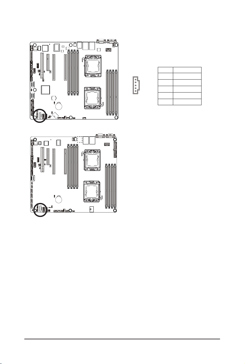
10) PMbus_CN_1 (Power management connector)
GA-7PCSL
GA-7PCSLX
GA-7PCSLN
5
1
Pin No. Denition
1 SMB CLK
2 SMB DATA
3 SMB Alert
4 GND Sense
5 3.3V Sense
Hardware Installation - 27 -
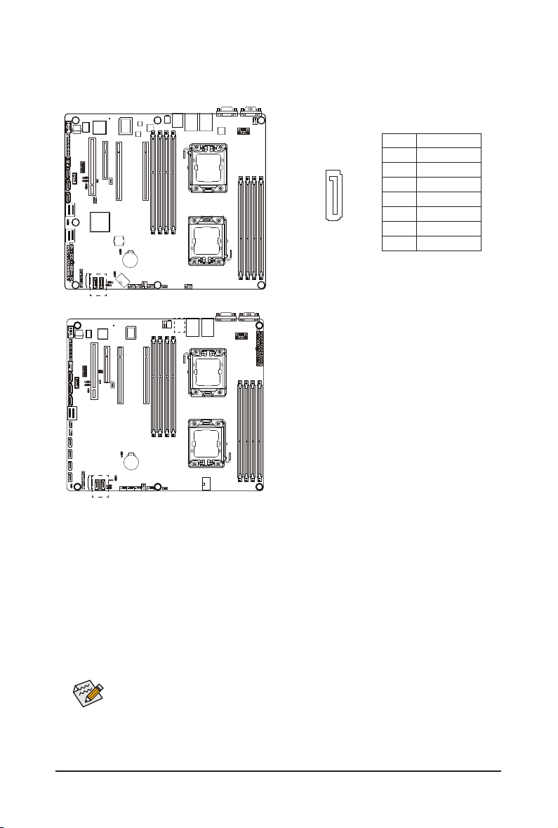
11) SATA0/1 (SATA 6Gb/s Connectors)
DEBUG
PORT
The SATA connectors conform to SATA 6Gb/s standard and are compatible with SATA 3Gb/s standard.
Each SATA connector supports a single SATA device.
Pin No. Denition
1 GND
2 TXP
3 TXN
4 GND
5 RXN
6 RXP
7 P5V/GND
GA-7PCSL
GA-7PCSLX
GA-7PCSLN
7
1
• A RAID 0 or RAID 1 conguration requires at least two hard drives. If more than two hard
drives are congured, the total number of hard drives must be an even number.
• A RAID 10 conguration requires four hard drives.
(Note) When a RAID conguration is built across the SATA 3Gb/s channels, the system performance of
the RAID conguration may vary depends on the devices are connected.
- 28 - Hardware Installation
 Loading...