

Page 1
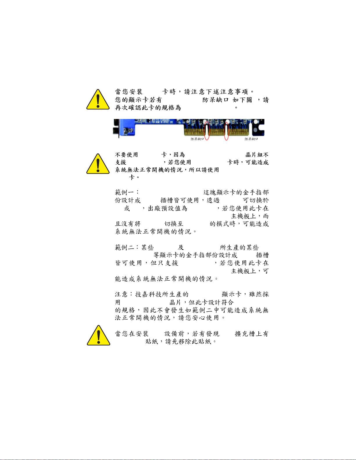
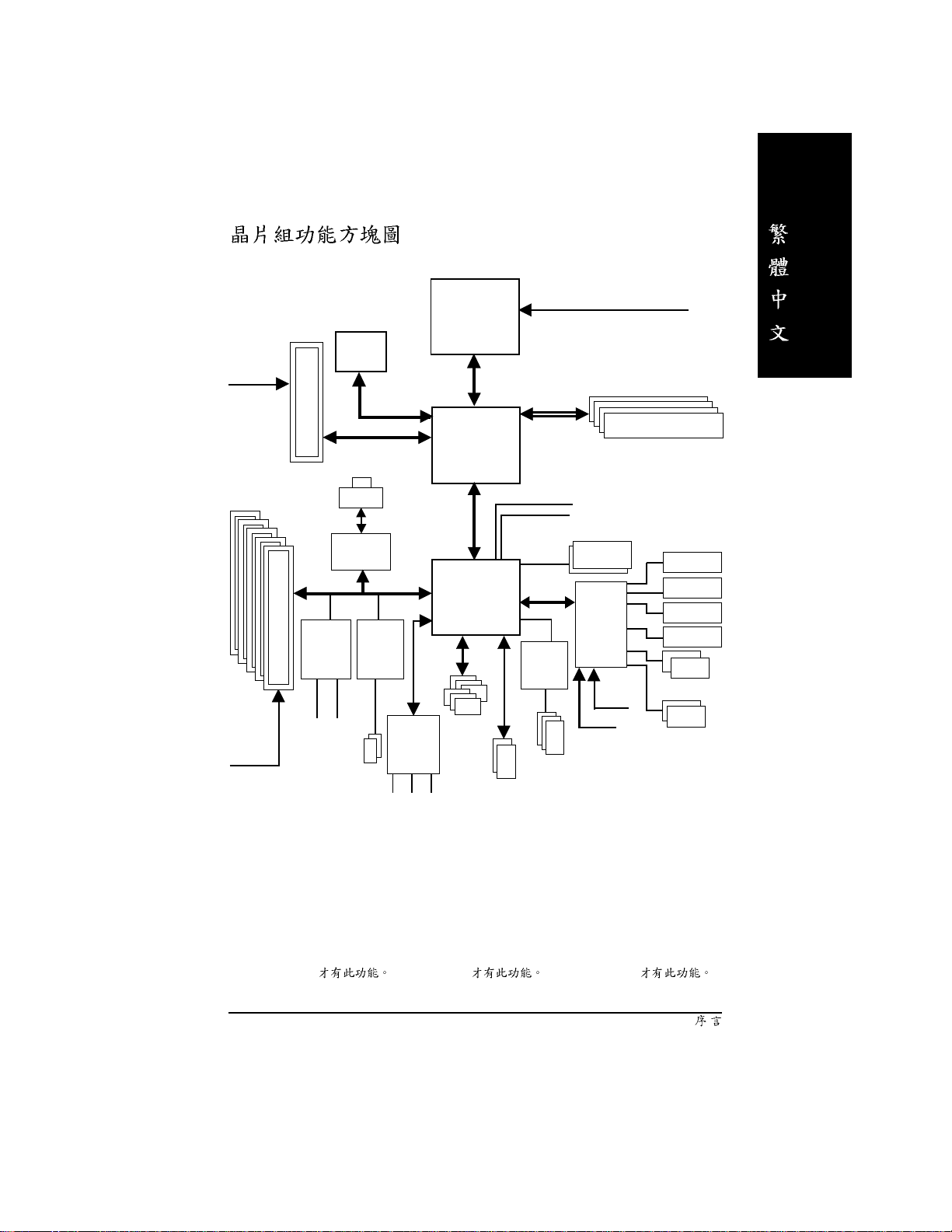
AGP
AGP 4X/8X ( )
AGP 4X/8X(1.5V)
AGP 2X
AGP 2X nVIDIA® nForce™ 2 IGP
AGP 2X(3.3V) AGP 2X(3.3V)
(1.5V)
AGP 4X/8X
AGP 4X/8X
Diamond Vipper V770
2X/4X Jumper
2X 4X 2X(3.3V)
GA-7N400V Pro2 / GA-7N400V / GA-7N400V-L
Jumper 4X(1.5V)
SiS 305 Power Color ATi
Rage 128 Pro
2X/4X
2X(3.3V)
GA-7N400V Pro2 / GA-7N400V / GA-7N400V-L
AG32S(G)
ATi Rage 128 Pro AGP4X(1.5V)
Dual BIOS
c_7n400vPro2_1001_f.p65 2003/9/18, ¤U¤È 04:211
PCI PCI
Page 2

c_7n400vPro2_1001_f.p65 2003/9/18, ¤U¤È 04:212
Page 3
Ausschlager Weg 41, 1F, 20537 Hamburg, Germany
( description of the apparatus, system, installation to which it refers)
GA-7N400V Pro2 / GA-7N400V / GA-7N400V-L
(reference to the specification under which conformity is declared)
in accordance with 89/336 EEC-EMC Directive
o EN 55011 Limits and methods of measurement
o EN 55013
o EN 55014 Limits and methods of measurement
o EN 55015 Limits and methods of measurement
o EN 55020
T EN 55022
o DIN VDE 0855
o part 10
o part 12
of radio disturbance characteristics of
industrial,scientific and medical (ISM
high frequency equipment
Limits and methods of measurement
of radio disturbance characteristics of
broadcast receivers and associated
equipment
of radio disturbance characteristics of
household electrical appliances,
portable tools and similar electrical
apparatus
of radio disturbance characteristics of
fluorescent lamps and luminaries
Immunity from radio interference of
broadcast receivers and associated
equipment
Limits and methods of measurement
of radio disturbance characteristics of
information technology equipment
Cabled distribution systems; Equipment
for receiving and/or distribution from
sound and television signals
Declaration of Conformity
We, Manufacturer/Importer
(full address)
G.B.T. Technology Träding GMbH
declare that the product
Mother Board
is in conformity with
o EN 61000-3-2*
T EN 60555-2
o EN 61000-3-3* Disturbances in supply systems cause
T EN 60555-3
T EN 50081-1
T EN 50082-1
o EN 55081-2
o EN 55082-2
o ENV 55104
o EN50091-2
Disturbances in supply systems cause
by household appliances and similar
electrical equipment “Harmonics”
by household appliances and similar
electrical equipment “Voltage fluctuations”
Generic emission standard Part 1:
Residual commercial and light industry
Generic immunity standard Part 1:
Residual commercial and light industry
Generic emission standard Part 2:
Industrial environment
Generic emission standard Part 2:
Industrial environment
lmmunity requirements for household
appliances tools and similar apparatus
EMC requirements for uninterruptible
power systems (UPS)
T CE marking
o EN 60065
o EN 60335
The manufacturer also declares the conformity of above mentioned product
with the actual required safety standards in accordance with LVD 73/23 EEC
Safety requirements for mains operated
electronic and related apparatus for
household and similar general use
Safety of household and similar
electrical appliances
Manufacturer/Importer
(Stamp)
Date : July 24, 2003
(EC conformity marking)
o EN 60950
o EN 50091-1
Safety for information technology equipment
including electrical bussiness equipment
General and Safety requirements for
uninterruptible power systems (UPS)
Signature:
Name:
Timmy Huang
Timmy Huang
c_7n400vPro2_1001_f.p65 2003/9/18, ¤U¤È 04:213
Page 4

DECLARA TION OF CONFORMITY
Per FCC Part 2 Section 2.1077(a)
Responsible Party Name:
Address:
Phone/Fax No:
hereby declares that the product
Product Name:
Model Number:
Conforms to the following specifications:
FCC Part 15, Subpart B, Section 15.107(a) and Section 15.109(a),
Class B Digital Device
Supplementary Information:
This device complies with part 15 of the FCC Rules. Operation is
subject to the following two conditions: (1) This device may not
cause harmful and (2) this device must accept any inference received,
including that may cause undesired operation.
Representative Person’s Name:
Signature:
G.B.T. INC. (U.S.A.)
17358 Railroad Street
City of Industry, CA 91748
(818) 854-9338/ (818) 854-9339
Motherboard
GA-7N400V Pro2 /GA-7N400V /GA-7N400V-L
ERIC LU
Eric Lu
Date:
July 24, 2003
c_7n400vPro2_1001_f.p65 2003/9/18, ¤U¤È 04:214
Page 5

GA-7N400V Pro2 / GA-7N400V / GA-7N400V-L
AMD Socket A
AMD Athlon™/ Athlon™ XP / Duron™ Socket A
Rev. 1001
12MC-7N400VP2-1001
Page 6
............................................................................ 4
............................................................................ 4
....................................................................... 5
.................................................................................................... 5
GA-7N400V Pro2
GA-7N400V
GA-7N400V-L
Layout ........................................................... 8
Layout ................................................................... 9
Layout ..............................................................10
- GA-7N400V Pro2 / GA-7N400V /GA-7N400V-L . 11
.................................................. 13
1 (CLK_SW)&(CLK_RATIO) ............................. 14
2 (CPU) ........................................................15
2-1 ................................................................................15
2-2 ...............................................................16
3 ...................................................................17
4 ............................................................................20
5 21
5-1 I/O ..........................................................................21
5-2 .....................................................................................23
BIOS .................................................. 39
(For Example BIOS Verson: E6)......................................... 40
CMOS .....................................................................................42
BIOS .............................................................................. 44
- 2 -N400V Pro2 / N400V
Page 7

..............................................................................47
.........................................................................................49
.........................................................................................54
PCI ...................................................................57
.........................................................................................58
/ ......................................................................................60
Fail-Safe .............................................................................61
Optimized ...........................................................................62
(Supervisor) / (User) .....................................63
SETUP ............................................................64
SETUP .......................................................65
......................................... 67
@BIOS™ .............................................................................................67
BIOS
/ / ..................................................78
Xpress Recovery
...............................................................................68
................................................................................84
..................................................................... 89
- 3 -
Page 8
N400V Pro2 / N400V
N400V Pro2 / N400V
GigaRAID
SATA RAID
(j)
(j)
GC-SATA ( )
( SATA x 1 x 1)
IDE x 3 / x 1
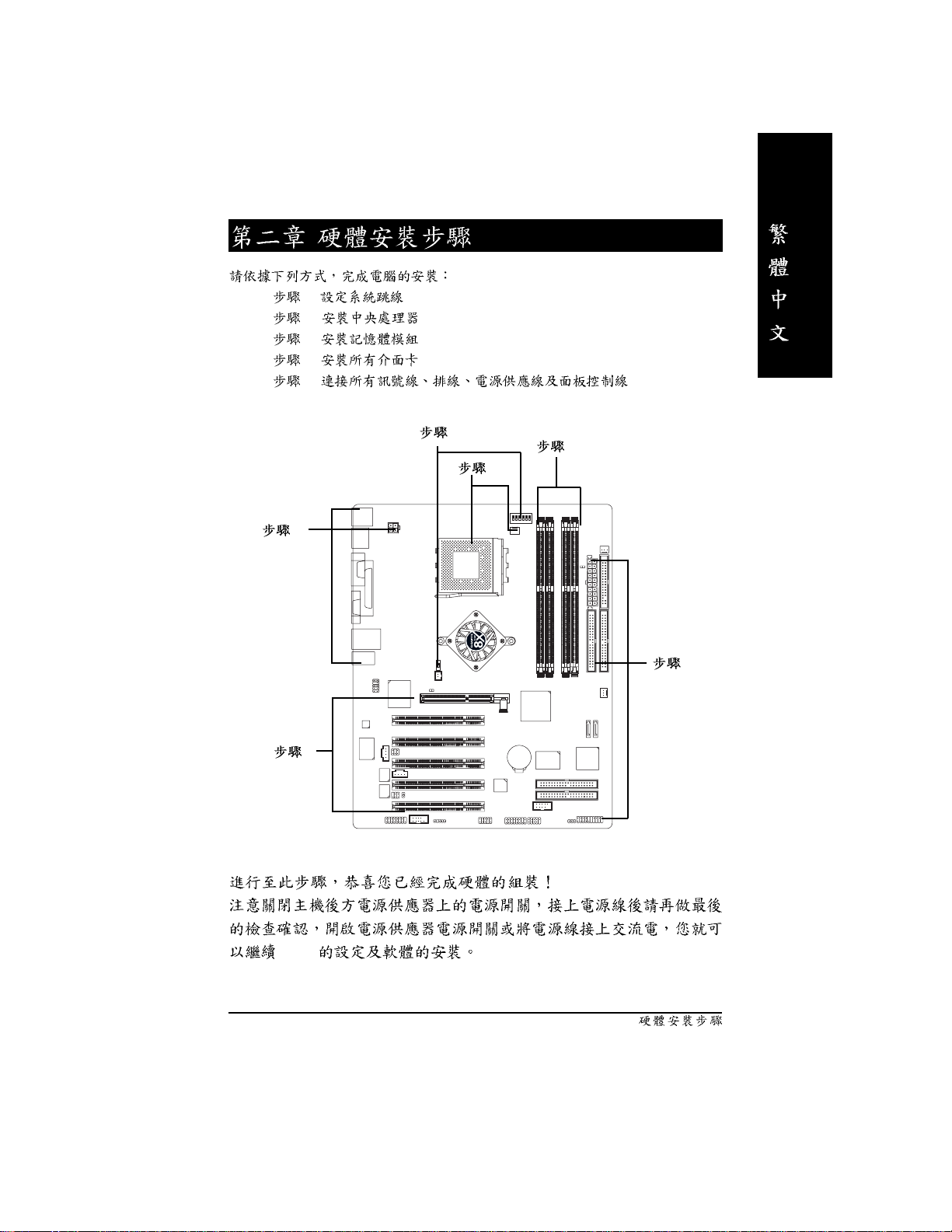
1.
2.
3. (CPU RAM)
4.
5. ATX
IDE x 1 / x 1
SATA x 2
(j)
IEEE1394 x 1
2 x 1
Audio Combo Kit x 1
(SURROUND-Kit + SPDIF Out Kit)
(j)
I/O
Motherboard Settings
(j)
ATX 12V (*)
(j)
(
kl
)
PCB
(*) ATX_12V
jGA-7N400V Pro2 k GA-7N400V lGA-7N400V-L
- 4 -N400V Pro2 / N400V
Page 9
ATX 30.5 x 24.4
N400V Pro2/N400V :
GA-7N400V Pro2 / GA-7N400V / GA-7N400V-L
AMD Athlon™ / Athlon™ XP / Duron™ (K7) Socket A
128K 512K/256K/64K
CPU
333/266/200 MHz FSB
1.4 GHz CPU
nVIDIA® nForce™ 2 IGP Memory/AGP/PCI
nVIDIA® nForce™ 2 MCP
4 184-pin DDR DIMM
DDR333/DDR266 DIMM
128MB/256MB/512MB/1GB unbuffered DRAM
3GB
2.5V DDR DIMM
I/O IT8712F
1 AGP AGP 8X/4X AGP3.0
PCI 33MHz PCI 2.2 compliant
5
IDE 2 IDE bus master (UDMA 33/ATA 66/ATA 100/ATA 133) IDE
4 ATAPI
Serial ATA
(j)
IDE3
GigaRAID IT8212F
(j)
2 Serial ATA (150MB/ )
SiI3112
CPU / /
IDE4
(j)
RAID Ultra ATA133/100, IDE
(j)
(j)
(j)
(j)
CPU /
CPU
CPU / /
CPU
(j)
(j)
CPU
.......
jGA-7N400V Pro2 k GA-7N400V lGA-7N400V-L
- 5 -
Page 10
1 (360K, 720K, 1.2M, 1.44M
2.88M bytes)
1
2 (COM1 & COM2)
6
USB 2.0/1.1 , x 4
IEEE1394 ( )
3
1
1
Realtek 8110S Gigabit
Realtek 8100C
1 RJ 45
Realtek ALC650 CODEC
Line Out : 2
Line In : 2 ( )
Mic In :
SPDIF In / Out
CD In / AUX In / Game Port
IDE RAID GigaRAID IT8212F
(j)
striping (RAID 0) mirroring (RAID 1)
striping+mirroring (RAID 0+RAID 1)
JBOD
ATA133 IDE
ATAPI
IDE bus master
ATA133/RAID ( BIOS )
Mirroring
BIOS LBA 13h
Normal/EPP/ECP
x 2 ( )
(j)
(
(j)
(l)
(jl)
/ ( )
.......
jGA-7N400V Pro2 k GA-7N400V lGA-7N400V-L
- 6 -N400V Pro2 / N400V
Page 11

SATA RAID Silicon Image SiI3112
(j)
Disk striping (RAID0) DISK Mirroring (RAID1)
UDMA 150 MB/
UDMA PIO
2 SATA
ACPI and ATA/ATAPI6
Serial ATA (SATA0 / SATA1)
IEEE1394
(j)
Built-in TI TSB43AB23
PS/2 PS/2 PS/2
BIOS AWARD BIOS
Dual BIOS
(j)
Face Wizard
Q-Flash
PS/2
PS/2
STR (Suspend-To-RAM)
AC Recovery
USB / S3
Thermal shutdown
@BIOS
BIOS (CPU/DDR/AGP)
BIOS (CPU/DDR/AGP)
CPU CPU
CPU
jGA-7N400V Pro2 k GA-7N400V lGA-7N400V-L
- 7 -
Page 12
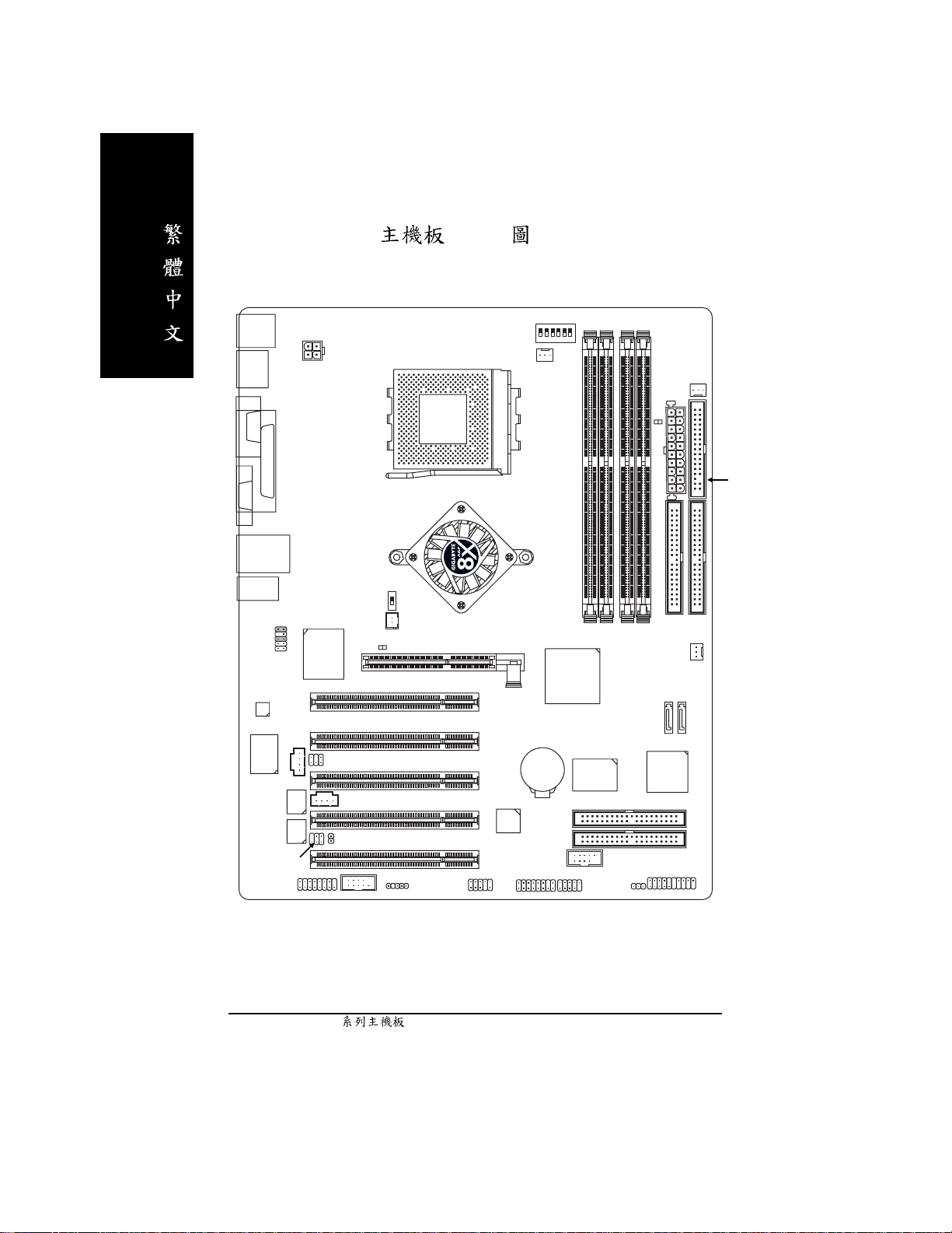
GA-7N400V Pro2 Layout
KB_MS
VGA
AUDIO
CODEC
USB
COM A
USB
IT8712F
BACKUP
BIOS
MAIN
BIOS
LPT
LAN
F_AUDIO
SPDIF_IO
RTL8110S
CD_IN
GAME
ATX_12V
SUR_CEN
AUX_IN
CI
COMB
CLK_SW
NB_FAN
2X_DET
SOCKET A
IR
PCI1
PCI2
PCI3
PCI4
PCI5
INFO_LINK
CLK_RATIO
CPU_FAN
nVIDIA® nForce™ 2
IGP
AGP
BAT
TSB43AB23
F2_1394
GA-7N400V Pro2
DDR1
DDR2
DDR3
F_USB
PWR_LED
nVIDIA
nForce™ 2
MCP
IDE4
IDE3
F1_1394
®
GigaRAID
IT8212
RAM_LED
DDR4
SYS_FAN
SiI3112
F_PANEL
ATX
IDE2
SATA0
SATA1
PWR_FAN
FDD
Dual Channel DDR
IDE1
- 8 -N400V Pro2 / N400V
Page 13
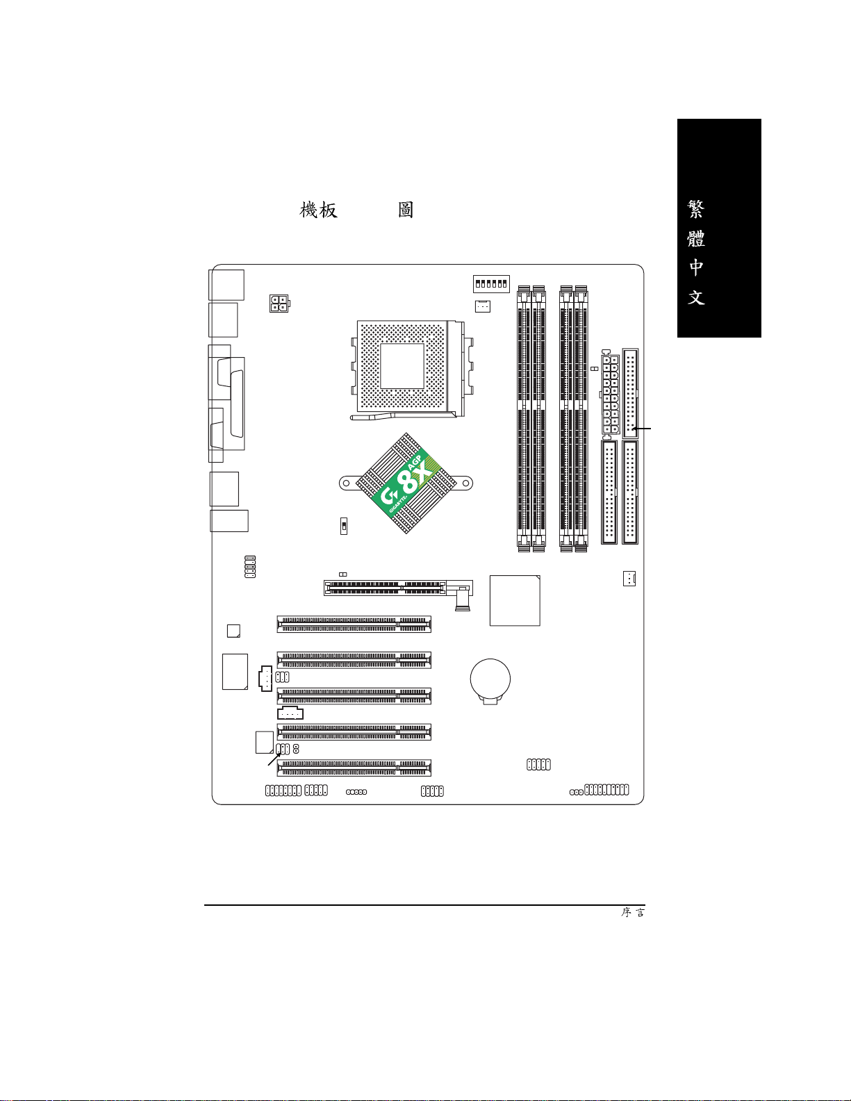
GA-7N400V Layout
KB_MS
COM A
VGA
AUDIO
CODEC
USB
USB
LPT
F_AUDIO
IT8712F
CD_IN
ATX_12V
CLK_SW
SUR_CEN
2X_DET
SOCKET A
CLK_RATIO
CPU_FAN
nVIDIA® nForce™ 2
PCI1
PCI2
PCI3
IGP
GA-7N400V
nVIDIA
AGP
nForce™ 2
MCP
BAT
®
DDR1
DDR2
DDR3
DDR4
SYS_FAN
ATX
RAM_LED
IDE2
FDD
Dual Channel DDR
IDE1
BIOS
SPDIF_IO
GAME
AUX_IN
CI
COM B
PCI4
PCI5
IR
INFO_LINK
F_USB
F_PANEL
PWR_LED
- 9 -
Page 14

GA-7N400V-L Layout
KB_MS
VGA
AUDIO
CODEC
USB
COM A
LPT
USB
IT8712F
LAN
F_AUDIO
RTL8100C
CD_IN
ATX_12V
CLK_SW
SUR_CEN
2X_DET
SOCKET A
CLK_RATIO
CPU_FAN
nVIDIA® nForce™ 2
PCI1
PCI2
PCI3
IGP
AGP
GA-7N400V-L
DDR1
®
nVIDIA
nForce™ 2
MCP
BAT
DDR2
DDR3
DDR4
SYS_FAN
ATX
RAM_LED
IDE2
FDD
Dual Channel DDR
IDE1
-L
BIOS
SPDIF_IO
GAME
AUX_IN
CI
COM B
PCI4
PCI5
IR
INFO_LINK
F_USB
F_PANEL
PWR_LED
- 10 -N400V Pro2 / N400V
Page 15
AGPCLK
(66MHz)
AGP
4X/8X
VGA
- GA-7N400V Pro2 / GA-7N400V / GA-7N400V-L
CPUCLK+/- (100/133/166MHz)
™
AMD-K7
CPU
System Bus
333/266/200MHz
nVIDIA
nForce™ 2
IGP
®
333/266/200MHz
DDR RAM
5 PCI
PCICLK
(33MHz)
GigaRAID
IT8212j
IDE4j
RJ45
RTL8110Sj
RTL8100Cl
SiI3112j
IDE3j
2 Serial
ATAj
AC97
CODEC
MIC
LINE-IN
nVIDIA
nForce™ 2
MCP
AC97 Link
6 USB
Ports
ATA33/66/100/133
LINE-OUT
®
LPC BUS
TI j
TSB43AB23
IDE Channels
12 MHz
14.318 MHz
BIOS
IT8712
33 MHz
3 IEEE1394j
IR
Game Port
Floppy
LPT Port
PS/2 KB/Mouse
24 MHz
2 COM Ports
jGA-7N400V Pro2 k GA-7N400V lGA-7N400V-L
- 11 -
Page 16
- 12 -N400V Pro2 / N400V
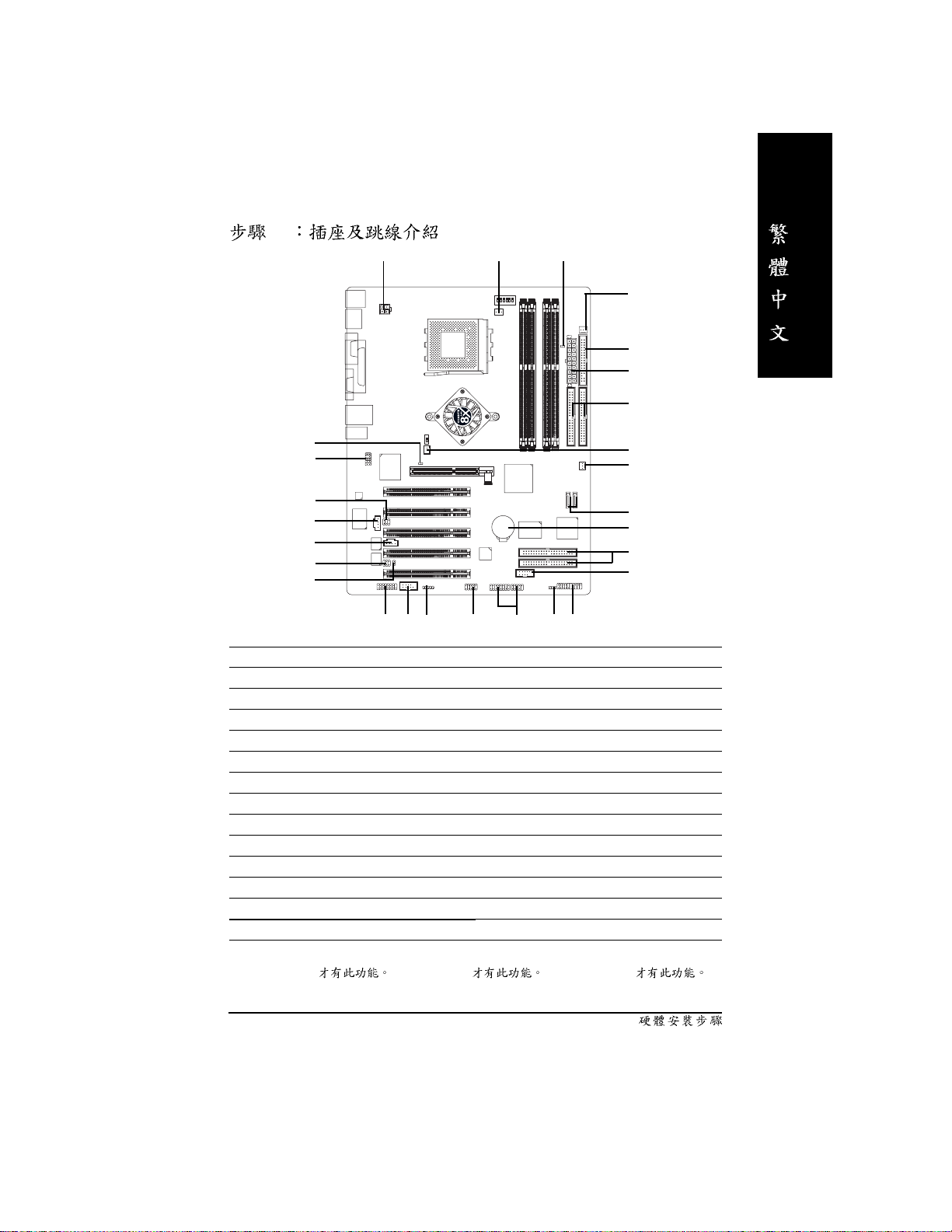
Page 17
1 - (CLK_SW)&(CLK_RATIO)
2 - (CPU)
3 4 5 -
1
2
5
4
3
5
BIOS
- 13 -
Page 18
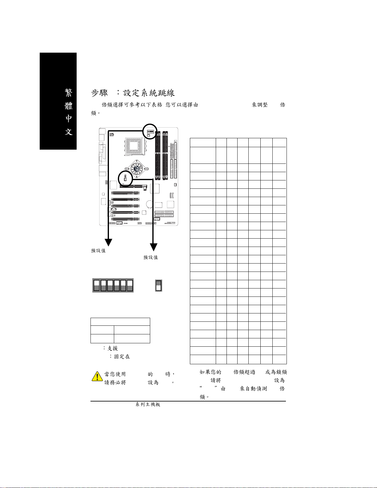
1 (CLK_SW)&(CLK_RATIO)
CPU
:
Auto (X X X X X X)
CLK_RATIO
51
6
CLK_SW
ON AUTO
OFF 100MHz
Auto FSB 333/266 MHz CPU
100MHz
234
( :OFF)
ON
FSB 200MHz CPU
, Dip Switch(CLK_RATIO) CPU
CLK_SW
ON
OFF
CLK_RATIO
RATIO 1 2 3 4 5 6
AUTO X X X X X X
(Default)
5x OOX O OO
5.5x X O X O O O
6x O X X O O O
6.5x X X X O O O
7x OOO X OO
7.5x X O O X O O
8x O X O X O O
8.5x X X O X O O
9x OOX X OO
9.5x X O X X O O
10x O X X X O O
10.5x X X X X O O
11x OOO O OO
11.5x X O O O O O
12x O X O O O O
12.5x X X O O O O
13x O O X O X O
13.5x X O X O X O
14x O X X O X O
15x O O O X X O
16x O X O X X O
16.5x X X O X X O
17x O O X X X O
18x X O X X X O
O: ON / X :OFF
200 MHz CPU
CLK_SW OFF
M CPU 18x
CPU, Dip Switch(CLK_RATIO)
AUTO BIOS CPU
- 14 -N400V Pro2 / N400V
Page 19

2 (CPU)
(CPU)
1.
2. CPU
2-1
1.
90
2.
- 15 -
Page 20
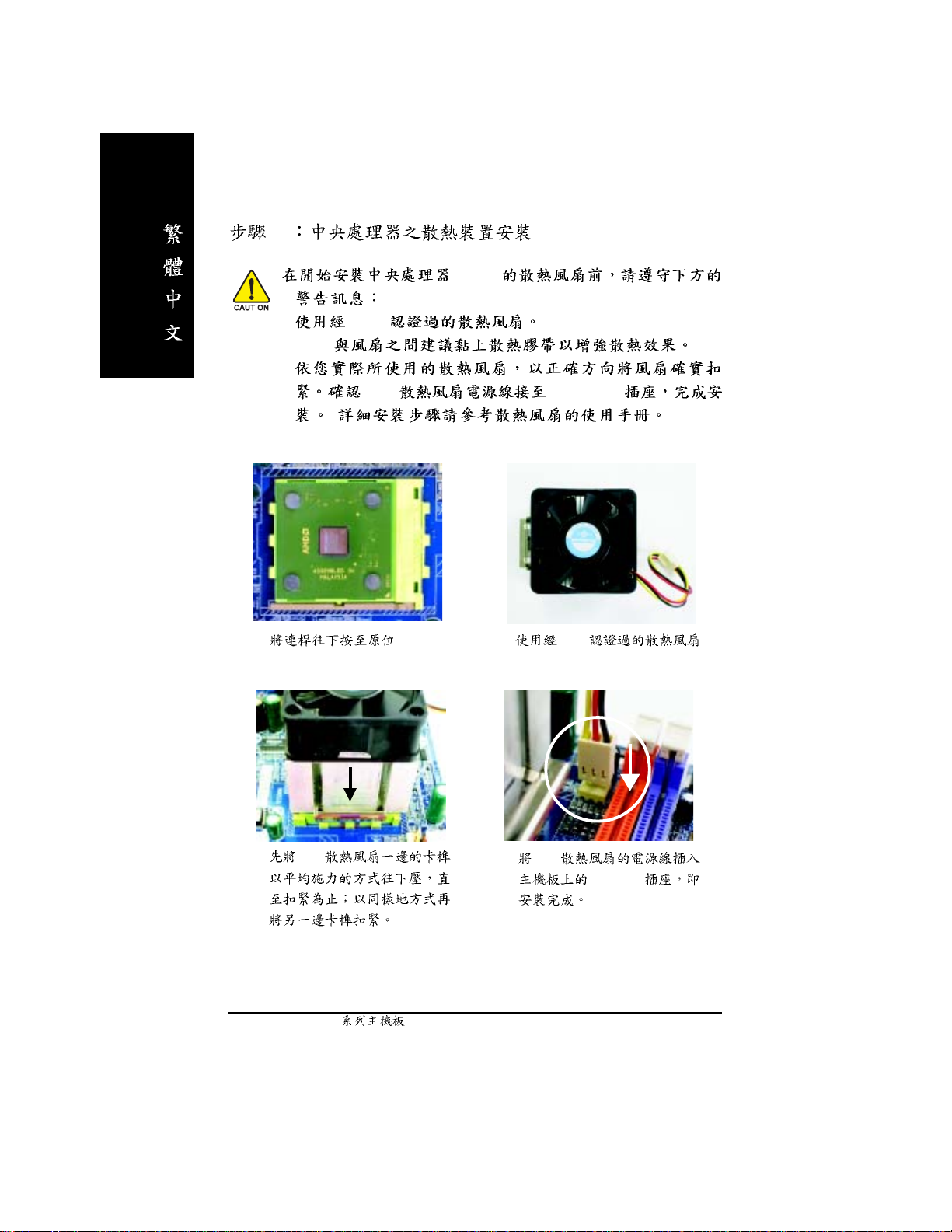
2-2
1. AMD
2.C PU
3.
( )
(CPU)
CPU CPU_FAN
1.
3. CPU
2. AMD
4. CPU
CPU FAN
- 16 -N400V Pro2 / N400V
Page 21

3
1. RAM_LE D
2.
4 (DIMM) BIOS
DDR
Unbuffered DDR DIMM
64 Mbit (2Mx8x4 banks) 64 Mbit (1Mx16x4 banks) 128 Mbit(4Mx8x4 banks)
128 Mbit(2Mx16x4 banks) 256 Mbit(8Mx8x4 banks) 256 Mbit(4Mx16x4 banks)
512 Mbit(16Mx8x4 banks) 512 Mbit(8Mx16x4 banks)
Total System Memory (Max3GB)
- 17 -
Page 22

1.
2.
3. DIMM
DDR
DDR(Double Data Rate) PC SDRAM
SDRAM
DDR OEM
DDR SDRAM
SDRAM DDR SDRAM
DDR 2.664GB/s DDR
DRAM
PC
- 18 -N400V Pro2 / N400V
Page 23

Dual Channel DDR:
GA-7N400V Pro2 / GA-7N400V / GA-7N400V-L Dual Channel Technology Dual
Channel Technology Memory Bus 5.3GB/s
(DDR333)
GA-7N400V Pro2 / GA-7N400V / GA-7N400V-L 4 DIMM Channel 2
DIMM
Channel A : DIMM 1, 2
Channel B : DIMM 3, 4
1. DDR Dual Channel
Technology Single Channel
2. DDR channel A channel B
Dual channel Technology
3. DDR Dual
Channel Technology
l Dual Channel Technology SS DS
DIMM 1 DIMM 2 DIMM 3 DIMM 4
2
3
4
DS/SS X DS/SS X
X DS/SS DS/SS X
DS/SS X X DS
X DS/SS X DS
DS/SS DS/SS DS/SS X
DS/SS DS/SS X DS
X DS/SS SS SS
DS/SS X SS SS
DS/SS DS/SS SS S S
l Dual Channel Technology SS DS
DIMM 1 DIMM 2 DIMM 3 DIMM 4
1
2
DS/SS X X X
X DS/SS X X
X X DS/SS X
XXXDS
DS/SS DS/SS X X
X X SS SS
DDR3 DDR4
size single side DDR
- 19 -
Page 24

4
1.
2. (
)
3.
4.
5.
6.
7. BIOS
8.
AGP .
AGP
2X(3.3V) , AGP_LED ,
2X (3.3V) .
AGP
/ AGP ,
. AGP
- 20 -N400V Pro2 / N400V
Page 25
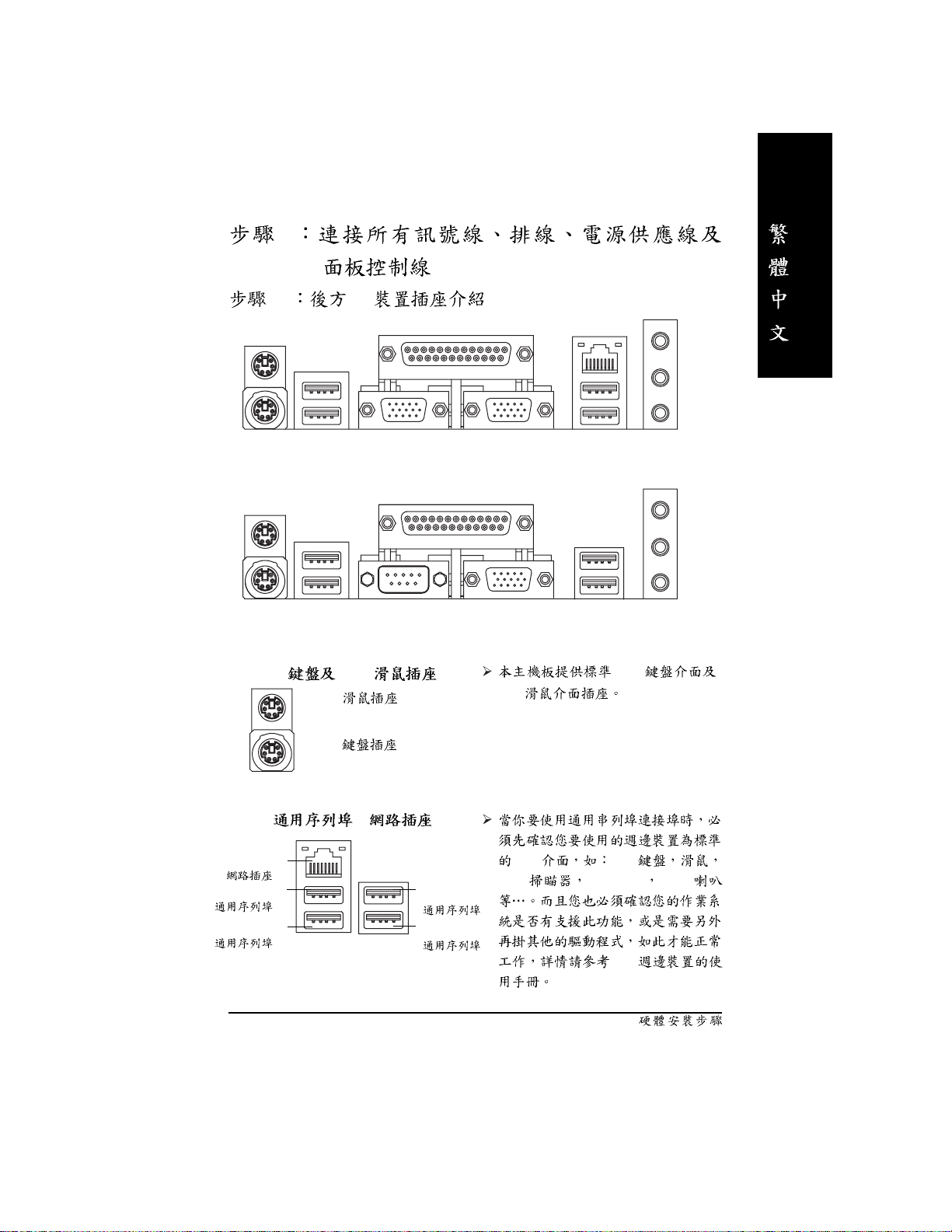
5
5-1 I/O
u
v
GA-7N400V Pro2 / GA-7N400V-L
u
v
GA-7N400V
u PS/2 PS/2
PS/2
(6 pin Female)
PS/2
(6 pin Female)
w
w
y
y
x
y
x
PS/2
PS/2
v /x /
LAN
( 1)
USB 0
( 0)
USB 1
( 1)
USB USB
USB USB ZIP USB
USB 2
( 2)
USB 3
( 3)
USB
- 21 -
Page 26
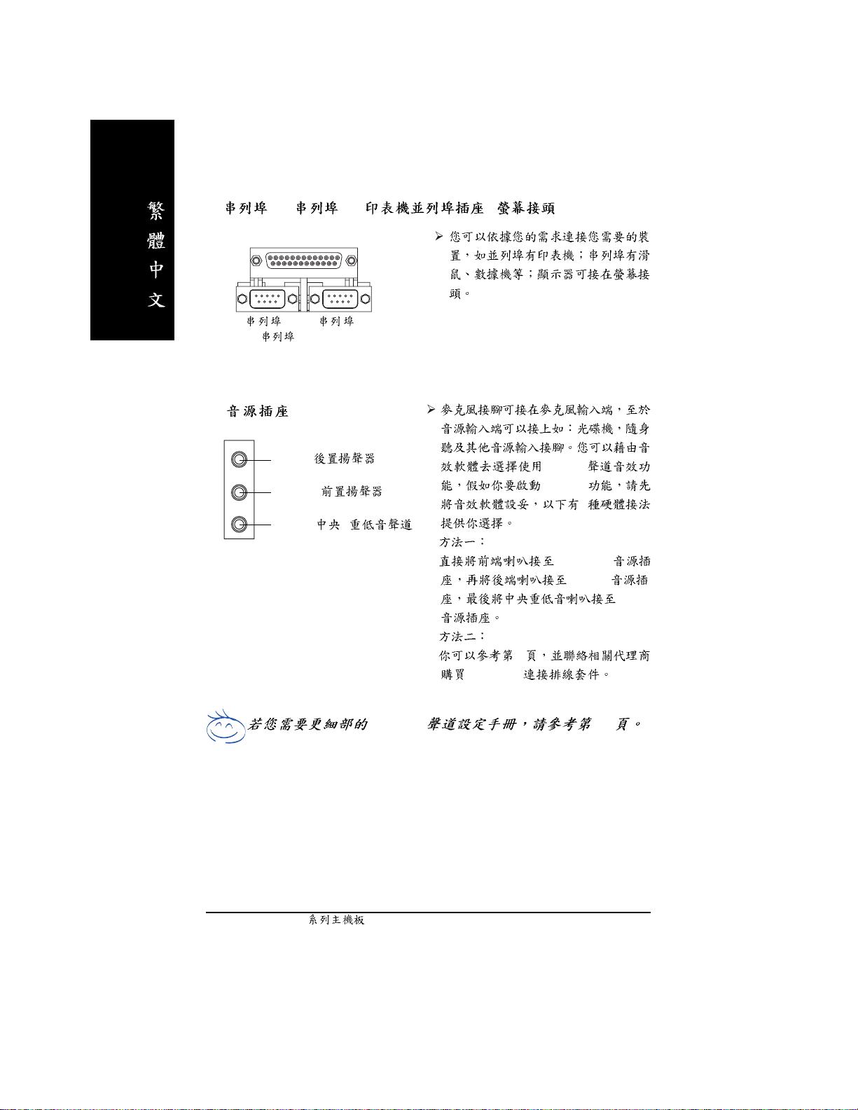
w 1 / 2 / /
y
1
(9 pin Male)
2
Line In ( )
Line Out ( )
MIC In (
/ )
2-/4-/6- 79
2-/4-/6-
6-channel
2
"Line Out"
"Line In"
"Mic In"
32
SUR_CEN
- 22 -N400V Pro2 / N400V
Page 27
5-2
1
3
14
(j)
5
7
2
8
15
16
17
19
20
18
27
1) ATX_12V
2) ATX
3) CPU_FAN
4) SYS_FAN
5) PWR_FAN
6) NB_FAN
7) FDD
8) IDE1 / IDE2
9) IDE3
10) SATA0
(j)
(j)
11) F_PANEL
12) BAT
13 ) PWR_LED
14) RAM_LED
(j)
(j)
/ IDE4
/ SATA1
(j)
(j)
(j)
6
4
(j)
10
12
(j)
9
21
24
26
23
(j)
22
25
13
11
15) 2X_DET
16) F_AUDIO
17) SUR_CEN
18) SPDIF_IO
19) CD_IN
20) AUX_IN
21) F_USB
22) F1_1394
(j)
/ F2_1394
(j)
23) IR
24) GAME
25) INFO_LINK
26) COMB
27) CI
jGA-7N400V Pro2 k GA-7N400V lGA-7N400V-L
- 23 -
Page 28
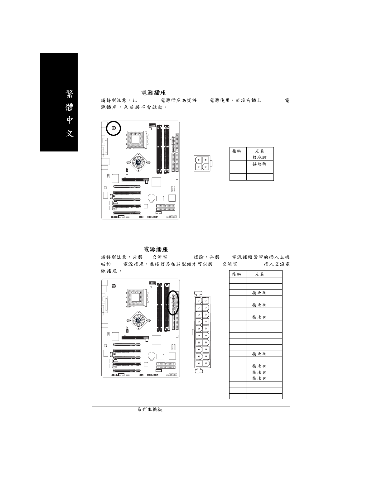
1) ATX_12V (+12V )
ATX_12V CPU ATX_12V
2) ATX (ATX Power )
AC (110/220V) ATX
ATX AC (110/220V)
1
3
4
2
1
2
3 +12V
4 +12V
1 3.3V
2 3.3V
3
11
20
1
10
4 VCC
5
6 VCC
7
8 Power Good
9 5V SB (stand by +5V)
10 +12V
11 3.3V
12 -12V
13
14 PS_ON(soft on/off)
15
16
17
18 -5V
19 VCC
20 VCC
- 24 -N400V Pro2 / N400V
Page 29
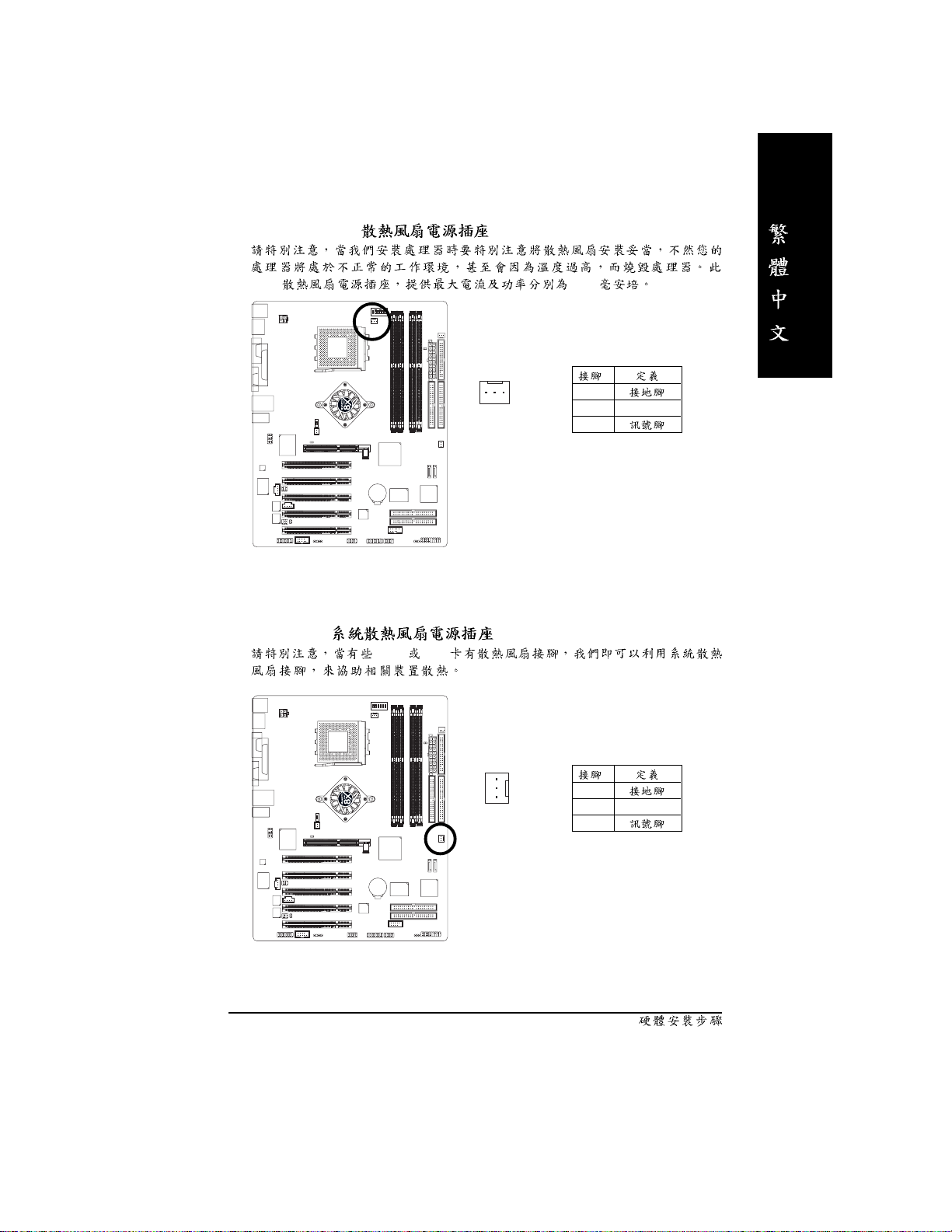
3) CPU_FAN (CPU )
CPU 600
4) SYS_FAN ( )
AGP PCI
1
1
1
2 +12V
3
1
2 +12V
3
- 25 -
Page 30
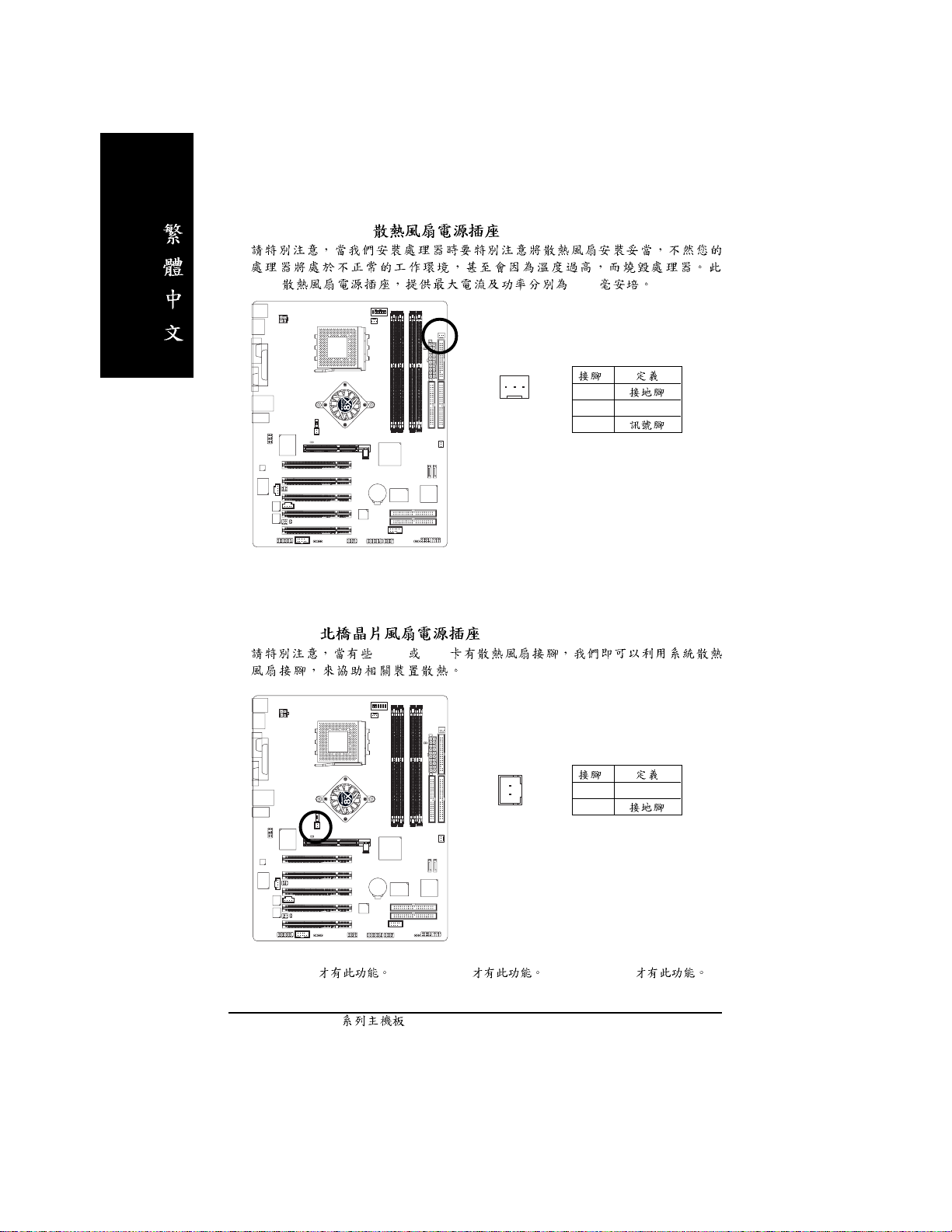
5) PWR_FAN (Power )
(j)
CPU 600
6) NB_FAN ( )
AGP PCI
1
(j)
1
1
2 +12V
3
1 VCC
2
jGA-7N400V Pro2 k GA-7N400V lGA-7N400V-L
- 26 -N400V Pro2 / N400V
Page 31

7) FDD ( )
Pin1 Pin1
34
2
8) IDE1 / IDE2 ( IDE )
IDE IDE
33
1
3940
- 27 -
IDE2
12
IDE1
Page 32

9) IDE3 / IDE4 (RAID ATA133 )(j )
IDE3 IDE4 BIOS RAID ATA133
ITE RAID
10) SATA0 / SATA1 (Serial ATA )(j)
Serial ATA 150MB Serial ATA
RAID BI OS Serial ATA RAID
SATA RAID
139
IDE4
IDE3
240
11
7
7
SATA0
SATA1
Silicon Image Sil3112 2 Serial
ATA
jGA-7N400V Pro2 k GA-7N400V lGA-7N400V-L
- 28 -N400V Pro2 / N400V
1
2 TXP
3 TXN
4
5 RXN
6 RXP
7
Page 33

11) F_PANEL (2 x 10 pins Connector)
Please connect the power LED, PC speaker, reset switch and power switch etc. of your chassis
front panel to the F_PANEL connector according to the pin assignment above.
Message LED/
Power/
Sleep LED
11
2
1
1
IDE Hard Disk Active LED
Soft Power
Connector
MSG+
MSG-
HD-
HD+
Reset Switch
PW+
PW-
1
RES+
RES-
Speaker Connector
1
NC
HD (IDE Hard Disk Active LED) Pin 1: LED anode(+)
Pin 2: LED cathode(-)
M
SPK (Speaker Connector) Pin 1: VCC(+) +5v
Pin 2- Pin 3: NC
Pin 4: Data(-)
RES (Reset Switch) Open: Normal Operation
Close: Reset Hardware System
SPEAK+
SPEAK-
20
19
M
PW (Soft Power Connector) Open: Normal Operation :
Close: Power On/Off : /
M
MSG (Message LED/Power/Sleep LED) Pin 1: LED anode(+)
Pin 2: LED cathode(-)
M
NC
- 29 -
Page 34

12) BATTERY ( )
13) PWR_LED
Power LED Suspend
power LED LED
+
+
CMOS ...
1.
2. 30
3.
4.
PWR_LED ON OFF
1
- 30 -N400V Pro2 / N400V
1 MPD+
2 MPD3 MPD-
Page 35

14) RAM_LED ( )
(AC110/220V)
STR
15)2X_DET (AGP 2X )
2X(3.3V) 2X_DET
2X(3.3V)
_
_
+
+
- 31 -
Page 36

16) F_AUDIO ( )
Pin5-6 Pin9-10 Jumper
10 9
2
1
17)SUR_CEN ( )
1 MIC
2
3 REF
4
5 Front Audio (R)
6 Rear Audio (R)
7 Reserved
8
9 Front Audio (L)
10 Rear Audio (L)
SUR_CEN
6
2
1
5
1 SUR OUTL
2 SUR OUTR
3
4
5 CENTER_OUT
6 BASS_OUT
- 32 -N400V Pro2 / N400V
Page 37

18) SPDIF_IO (SPDIF / )
Sony/Philip Digital Interfac e Format / SPDIF
(AC-3)
(SPDIF In) SPDIF_IO
SPDIF_IO
19)CD_IN ( )
CD-ROM DVD-ROM CD
62
1
5
1 VCC
2
3 SPDIF
4 SPDIFI
5
6
1
1
2
3
4
- 33 -
Page 38

20)AUX_IN ( )
MPEG
21)F_USB ( )
USB
1
USB
1
2
3
4
- 34 -N400V Pro2 / N400V
210
19
1
2
3 USB Dx4 USB Dy5 USB Dx+
6 USB Dy+
7
8
9
10
Page 39

22) F1_1394 / F2_1394 (IEEE1394 )
1394 IEEE1394 (Insitute of Electrical Eletro nics
Engineers)
IEEE1394
(j)
IEEE1394
23)IR ( )
F1_1394
Pin No. Definition
216
1
1
2
3 TPA0+
4 TPA05
6
7 TPB0+
8 TPB09
10
1 1 TPA1+
12 TPA113
14
15 TPB1+
16 TPB1-
15
IR
1
5
F2_1394
210
1
9
1 TPA2+
2 TPA23
4
5 TPB2+
6 TPB27
8
9
10
IR
1 +5V
2
3
4
5
jGA-7N400V Pro2 k GA-7N400V lGA-7N400V-L
- 35 -
Page 40

24) GAME ( )
25)INFO_LINK
1
2 GRX1_R
3
2
1
16
15
4 GPSA2
5
6 GPX2_R
7 GPY2_R
8 MSI_R
9 GPSA1
10
11 GPY1_R
12
13 GPSB1
14 MSO_R
15 GPSB2
16
1 SMBCLK
102
1
9
2
3 SMBDATA
4 GPIO
5
6
7
8
9 +12V
10 +12V
- 36 -N400V Pro2 / N400V
Page 41

26) CI (Chassis Intrusion )
1
1
2
- 37 -
Page 42

- 38 -N400V Pro2 / N400V
Page 43

BIOS
AMI BIOS CMOS SETUP
CMOS SETUP CMOS SRAM
CMOS SRAM
BIOS POST Power On Self Test
Del AMI BIOS CMOS SETUP BIOS
BIOS "Ctrl+F1"
< >
< >
< >
< >
<Enter>
<Esc> SETUP
<Page Up>
<Page Down>
<F1>
<F2>
<F3>
<F4>
<F5> ( )
<F6> Fail-Safe ( )
<F7> Optimized ( )
<F8> BIOS / Q-Flash
<F9>
<F10> CMOS SETUP
BIOS- 39 -
Page 44

SETUP
SETUP
F1
BIOS CMOS SETUP
<Esc>
(For Example BIOS Verson: E6)
CMOS SETUP ,
, Enter
CMOS Setup Utility-Copyright (C) 1984-2003 Award Software
} Standard CMOS Features
} Advanced BIOS Features
} Advanced Chipset Features
} Integrated Peripherals
} Power Management Setup
} PnP/PCI Configurations
} PC Health Status
ESC: Quit higf: Select Item
F8: Dual BIOS / Q-Flash F10: Save & Exit Setup
Time, Date, Hard Disk Type...
1
BIOS
} Frequency/Voltage Control
Load Fail-Safe Defaults
Load Optimized Defaults
Set Supervisor Password
Set User Password
Save & Exit Setup
Exit Without Saving
l Standard CMOS Features ( CMOS )
l Advanced BIOS features ( BIOS )
BIOS
...
"Ctrl+F1"
- 40 -N400V Pro2 / N400V
Page 45

l Advanced Chipset features ( )
l Integrated peripherals ( )
COM Port IRQ LPT
Port
SPP EPP ECP IDE PIO Mode ..
l Power management setup ( )
CPU GREEN
l PnP/PC I configuration ( PCI )
ISA PnP PCI
l PC Healt h Status ( )
,
l Frequency/Voltage Control ( / )
CPU
l Load Fail-Safe defaults ( Fail-Safe )
BIOS CMOS
l Lo a d O pti m i ze d de fa ults ( Optimized )
Optimized CMOS
l Set Supe rvisor password ( )
SETUP CMOS
l Set User pass word ( )
PC BIOS
l Save & exit se tup ( )
SETUP BIOS
F10
l Exit without save ( SETUP )
<ESC>
BIOS- 41 -
Page 46

CMOS
CMOS Setup Utility-Copyright (C) 1984-2003 Award Software
Standard CMOS Features
Date (mm:dd:yy) Tue, May 20 2003 Item Help
Time (hh:mm:ss) 22:31:24 Menu Level u
Change the day, month,
} IDE Primary Master [None] year
} IDE Primary Slave [None]
} IDE Secondary Master [None] <Week>
} IDE Secondary Slave [None] Sun. to Sat.
Drive A [1.44M, 3.5"] <Month>
Drive B [None] Jan. to Dec.
Floppy 3 Mode Support [Disabled]
<Day>
Halt On [All, But Keyboard] 1 to 31 (or maximum
allowed in the month)
Base Memory 640K
Extended Memory 95M <Year>
Total Memory 96M 1999 to 2098
higf: Move Enter:Select +/-/PU/PD: Value F10: Save ESC:Exit F1: General Help
F5: Previous Values F6: Fail-Safe Defaults F7: Optimized Defaults
Date(mm:dd:yy) ( )
(mm) 1 12
(dd) 1 28 /29/30/31
(yy ) 1999 2098
2 CMOS
/ /
/ /
- 42 -N400V Pro2 / N400V
Page 47

Time(hh:mm:ss) ( )
24
13 : 00 : 00 RTC
IDE Primary Master (Slave) / IDE Secondary Master (Slave)
(
1 IDE 2
CMOS
1 User TYPE CYLS HEADS
SECTORS MODE
2 AUTO TYPE MODE AUTO BIOS POST
IDE
Capacity MegaBytes)
Access Mode CHS/ LBA/ Large/ Auto
Cylinder
Head
Precomp Write precomp
Landing Zone Landing Zone
Sector Numb er of s ectors ( )
/ )
IDE
"NONE" <E nter>
Drive A / Drive B ( A:/ B: )
None
360K, 5.25" 5. 25 360KB
1.2M, 5.25" 5 . 2 5 1.2MB
720K, 3.5" 3 720KB
1.44M, 3.5" 3 1.4 4MB
2.88M, 3.5" 3 2.8 8MB
Floppy 3 Mo de Su ppo r t ( 3 Mode )
Disabled 3 Mode ( )
Drive A A: 3 Mode
Drive B B: 3 Mode
Both A: B: 3 Mode
BIOS- 43 -
Page 48

Halt on ( )
POST
All Errors
No Errors
All, But Ke yboard ( )
All, But Diskette
All, But Disk/Key
Memory ( )
BIOS POST(Power On Self Test)
STANDARD CMOS SETUP
Base Memory
PC 64 0KB MS-DOS
Extended Memory
Base Other Memory
Module
- 44 -N400V Pro2 / N400V
Page 49

BIOS
CMOS Setup Utility-Copyright (C) 1984-2003 Award Software
Advanced BIOS Features
First Boot Device [Floppy]
Second Boot Device [HDD-0]
Third Boot Device [CDROM]
x SATA/RAID/SCSI Boot Order SCSI
Boot Up Floppy Seek [Disabled]
Flexible AGP 8X [Auto]
Init Display First [PCI]
higf: Move Enter:Select +/-/PU/PD: Value F10: Save ESC:Exit F1: General Help
F5: Previous Values F6: Fail-Safe Defaults F7: Optimized Defaults
3 BIOS
First / Second / Third Boot device ( / / )
Item Help
Menu Level u
Select onboard RAID or
PCI SCSI boot rom
order
Floppy
LS120 LS 120
HDD-0~3
SCSI SCSI
CDROM
LAN
USB-CDROM USB-CDROM
USB-ZIP USB-ZIP
USB-FDD USB-FDD
USB-HDD USB-HDD
ZIP ZIP
Disabled
BIOS- 45 -
Page 50

SATA / RAID / SCSI Boot Order ( SATA/RAID/SCSI )
SATA/RAID/SCSI
SCSI SCSI
RAID RAID
SATA Serial ATA
Boot Up Floppy Seek ( )
PC POST FLOPPY SEEK
Enabled Floppy Seek ( )
Disabled Floppy Seek
Flexible AGP 8X
8Auto AGP AGP
( )
84X AGP 4X
Init Display First ( )
AGP PCI
PCI PCI ( )
Onboard/AGP AGP
- 46 -N400V Pro2 / N400V
Page 51

CMOS Setup Utility-Copyright (C) 1984-2003 Award Software
Advanced Chipset Features
System Performance [Normal]
FSB Frequency [133MHz]
Memory Frequency By SPD
Resulting Frequency 266MHz
Frame Buffer Size [32MB]
AGP Frequency [Normal]
higf: Move Enter:Select +/-/PU/PD: Value F10: Save ESC:Exit F1: General Help
F5: Previous Values F6: Fail-Safe Defaults F7: Optimized Defaults
4 Chipset
Item Help
Menu Level u
[Normal] - Use the
most stable settings.
[Turbo] -Use over
colocked settings for
higher performance but
with higher risk of
instability.
System Performance ( )
Normal ( )
Turbo
Manual
FSB Freq uency (MHz )
100MHz (FSB) 1 00MHz
133MHz (FSB) 133MHz ( )
166MHz (FSB) 1 66MHz
BIOS- 47 -
Page 52

Memory Frequency
By SPD SPD ( )
50%~200% 50% 200%
Auto
Resulting Frequency
(FSB)/
Frame Buffer Size
VGA Frame Buffer
8MB 8MB
16MB 16MB
32MB 32MB ( )
64MB 64MB
128MB 128MB
Disabled
AGP Frequency
Normal AGP ( )
50MHz ~ 100MHz AGP 50MHz 100MHz
- 48 -N400V Pro2 / N400V
Page 53

CMOS Setup Utility-Copyright (C) 1984-2003 Award Software
Integrated Peripherals
On-Chip Primary PCI IDE [Enabled]
On-Chip Secondary PCI IDE [Enabled]
USB Host Controller [V1.1+V2.0]
USB Keyboard Support [Disabled]
USB Mouse Support [Disabled]
AC97 Audio [Auto]
Onboard LAN Chip
Onboard H/W 1394
Onboard H/W Serial ATA
Serial ATA Function
Onboard H/W RAID
Onboard LAN Boot ROM
(jl)
(j)
(j)
(j)
(j)
(jl)
[Enabled]
[Enabled]
[Enabled]
[RAID]
[Enabled]
[Disabled]
Onboard Serial Port 1 [3F8/IRQ4]
Onboard Serial Port 2 [2F8/IRQ3]
UART Mode Select [Normal]
x UR2 Duplex Mode Half
Onboard Parallel Port [378/IRQ7]
Parallel Port Mode [ECP]
ECP Mode Use DMA [3]
Game Port Address [201]
Midi Port Address [330]
Midi Port IRQ [10]
Item Help
Menu Level u
If a hard disk
controller card is
used, set at Disabled
[Enabled]
Enabled onboard IDE
Port
[Disabled]
Disabled onboard IDE
Port
higf: Move Enter:Select +/-/PU/PD: Value F10: Save ESC:Exit F1: General Help
F5: Previous Values F6: Fail-Safe Defaults F7: Optimized Defaults
5
jGA-7N400V Pro2 k GA-7N400V lGA-7N400V-L
BIOS- 49 -
Page 54

On-Chip Primary PCI IDE ( channel PCI IDE )
Enabled channel IDE ( )
Disabled
On-Chip Secondary PCI IDE ( channel IDE )
Secondary IDE
Enabled channel PCI IDE ( )
Disabled
USB Host Controller
USB Controller
Disabled USB Controller
V1.1+V2.0 USB1.1 USB2 .0 ( )
V1.1 USB1.1
USB Keyboar d Support ( USB )
Enabled USB ( USB
USB Enabled)
Disabled US B ( )
USB Mouse S upport ( USB )
Disabled US B ( )
Enabled USB ( USB Device
USB Enabled)
AC97 Audio
Auto BIOS AC97 Audio ( )
Disabled AC97 Audio
Onboard LAN chip
Enabled BIOS LAN ( )
Disabled
jGA-7N400V Pro2 k GA-7N400V lGA-7N400V-L
(jl)
- 50 -N400V Pro2 / N400V
Page 55

Onboard H/W 1394
Enabled BIOS IEEE1394 ( )
Disabled
(j)
Onboard H/W Serial ATA ( SATA)
Enabled SAT A ( )
Disabled
Serial ATA Function
RAID Serial ATA RAID ( )
BASE Serial AT A BASE
(j)
Onboard H/W RAID ( RAID)
Enabled IDE RAID ( )
Disabled
Onboard LAN Boot ROM
Enabled on-chip LAN
Disabled ( )
(jl)
(j)
(j)
Onboard Serial Port 1 ( 1)
Disabled 1
3F8/IRQ4 1 COM 1 3F8 ( )
2F8/IRQ3 1 COM 2 2F8
3E8/IRQ4 1 COM 3 3E8
2E8/IRQ3 1 COM 4 2E8
Auto BIOS
Onboard Serial Port 2 ( 1)
Disabled 2
3F8/IRQ4 2 COM 1 3F8
2F8/IRQ3 2 COM 2 2F8 ( )
3E8/IRQ4 2 COM 3 3E8
2E8/IRQ3 2 COM 4 2E8
Auto BIOS
jGA-7N400V Pro2 k GA-7N400V lGA-7N400V-L
BIOS- 51 -
Page 56

UART Mode Select
Normal I/O ( )
IrDA I/O IrDA
ASKIR I/O ASKIR
UR2 Duplex Mode
UART Mode Select [Normal] [SCR]
Full IR
Half IR ( )
Onboard Parallel port ( )
Disabled
378/IRQ7 378/IRQ7 ( )
278/IRQ5 278/IRQ5
3BC/IRQ7 3BC/IRQ7
Parallel Port Mode ( )
SPP
EPP EPP Enhanced Parallel Port
ECP ECP Extended Capabilities Port ( )
ECP+EPP EPP EC P
ECP Mode Use DMA
Parallel P ort Mode "ECP" "ECP+EPP"
3 ECP Mode use DMA 3 ( )
1 ECP Mode use DMA 1
Game Port Address
Disabled
201 Game Port Address 201 ( )
209 Game Port Address 209
Midi Port Addres s
Disabled
330 Midi Port Address 330 ( )
300 Midi Port Address 300
- 52 -N400V Pro2 / N400V
Page 57

Midi Port IRQ
5 Midi Port IRQ 5
10 Midi Port IRQ 10 ( )
BIOS- 53 -
Page 58

CMOS Setup Utility-Copyright (C) 1984-2003 Award Software
Power Management Setup
ACPI Suspend Type [S1(POS)]
Soft-Off by PWR-BTTN [Instant-off]
PME Event Wake Up [Enabled]
ModemRingOn [Enabled]
S3 Resume by USB [Disabled]
Resume by Alarm [Disabled]
x Date (of Month) Alarm Everyday
x Time (hh:mm:ss) Alarm 0 : 0 : 0
Power On by Mouse [Disabled]
Power On by Keyboard [Disabled]
x KB Power ON Password Enter
AC Back Function [Soft-Off]
higf: Move Enter:Select +/-/PU/PD: Value F10: Save ESC:Exit F1: General Help
F5: Previous Values F6: Fail-Safe Defaults F7: Optimized Defaults
6
Item Help
Menu Level u
[S1]
Set suspend type to
Power On Suspend under
ACPI OS
[S3]
Set suspend type to
Suspend to RAM under
ACPI OS
ACPI Suspend Type
S1(POS) ACPI Suspend type S1(Power On Suspend) ( ).
S3(STR) ACPI Suspend type S3(Suspend to RAM).
Off by Power button ( )
Instant-off Soft-off ( )
Delay 4 Sec. Soft-off 4 4
- 54 -N400V Pro2 / N400V
Page 59

PME Event Wake Up ( )
+5VSB 1
Disabled
Enabled ( )
ModemRingOn ( )
Disabled
Enabled ( )
S3 Resume by US B (U SB )
Enabled S3 USB
Disabled ( )
Enabled
Resume by Alarm ( )
Enabled
Disabled ( )
Enabled
Date (of Month) Alarm Everyday, 1~31
Time (hh: mm: ss) Alarm (0~23) : (0~59) : (0~59)
Power On by Mouse ( )
Disabled ( )
Mouse Click
Power On by Keyboard ( )
Disabled ( )
Password 1-5
Keyboard 98 Windows 98 "power"
KB Power On Password ( )
"Power On by Keyboard" "Passowrd"
Enter 1-5 Enter
BIOS- 55 -
Page 60

AC Back Function ( )
Soft-Off Soft Power Button
( )
Full-On
Memory
- 56 -N400V Pro2 / N400V
Page 61

PCI
CMOS Setup Utility-Copyright (C) 1984-2003 Award Software
PnP/PCI Configurations
PCI 1/PCI 5 IRQ Assignment [Auto] Item Help
PCI 2 IRQ Assignment [Auto] Menu Level u
PCI 3 IRQ Assignment [Auto] Device(s) using this
PCI 4 IRQ Assignment [Auto] INT :
Network Cntrlr
- Bus 1 Dev 11 Func 0
higf: Move Enter:Select +/-/PU/PD: Value F10: Save ESC:Exit F1: General Help
F5: Previous Values F6: Fail-Safe Defaults F7: Optimized Defaults
7 PCI
PCI1/PCI5 IRQ Assignment
Auto IRQ PCI 1/PCI5. ( )
3,4,5,7,9.,10,11,12,14,15 Set 3,4,5,7,9,10,11,12,14,15 to PCI1/PCI5.
PCI2 IRQ Assignment
Auto IRQ PCI 2. ( )
3,4,5,7,9.,10,11,12,14,15 Set 3,4,5,7,9,10,11,12,14,15 to PCI2.
PCI3 IRQ Assignment
Auto IRQ PCI 3. ( )
3,4,5,7,9.,10,11,12,14,15 Set 3,4,5,7,9,10,11,12,14,15 to PCI 3.
PCI4 IRQ Assignment
Auto IRQ PCI 4. ( )
3,4,5,7,9.,10,11,12,14,15 Set 3,4,5,7,9,10,11,12,14,15 to PCI 4.
BIOS- 57 -
Page 62

CMOS Setup Utility-Copyright (C) 1984-2003 Award Software
PC Health Status
Reset Case Open Status [Disabled] Item Help
Case Opened Yes Menu Level u
Vcore OK [Disabled]
DDR25V OK Don't reset case
+3.3V OK open status
+5V OK
+12V OK [Enabled]
Current System Temperature 32
Current CPU Temperature 34oC status at next boot
Current CPU FAN Speed 4687 RPM
Current SYSTEM FAN Speed 0 RPM
Current POWER FAN Speedj 0 RPM
CPU Warning Temperature [Disabled]
CPU FAN Fail Warning [Disabled]
POWER FAN Fail Warningj [Disabled]
SYSTEM FAN Fail Warning [Disabled]
CPU Smart FAN Controlj [Enabled]
higf: Move Enter:Select +/-/PU/PD: Value F10: Save ESC:Exit F1: General Help
F5: Previous Values F6: Fail-Safe Defaults F7: Optimized Defaults
8
o
C Clear case open
Reset Case Open Status
Disabled ( )
Enabled
Case Opened
"Case Opened" "No"
"Case Opened" "Reset Case Open Status" "Enable"
"Case Opened" "Yes"
- 58 -N400V Pro2 / N400V
Page 63

Current Voltage (v) Vcore / DDR25V / +3.3V / +5V / +12V
Current System Temperature
Current CPU Temperature
CPU
CPU FAN / POWERj / SYSTEM FAN Speed (RPM)
CPU/ /
CPU Warning Temperature
60oC / 140oF CPU 60oC / 140oF
70oC / 158oF CPU 70oC / 158oF
80oC / 176oF CPU 80oC / 176oF
90oC / 194oF CPU 90oC / 194oF
Disabled CPU ( )
CPU / POWERj / SYSTEM FAN Fail Warning
(CPU / / )
Disabled CPU / / ( )
Enabled CPU / /
CPU Smart FAN Contr o lj ( CPU )
Enabled CPU CPU 40oC
CPU CPU 40oC CP U
( )
Disabled
jGA-7N400V Pro2 k GA-7N400V lGA-7N400V-L
BIOS- 59 -
Page 64

/
CMOS Setup Utility-Copyright (C) 1984-2003 Award Software
Frequency/Voltage Control
VCORE OverVoltage Control [Normal]
DIMM OverVoltage Control [Normal]
AGP OverVoltage Control [Normal]
higf: Move Enter:Select +/-/PU/PD: Value F10: Save ESC:Exit F1: General Help
F5: Previous Values F6: Fail-Safe Defaults F7: Optimized Defaults
9 /
CMOS 20
CPU
VCORE OverVoltage Control (CPU )
Normal CPU .( )
+5% / +7.5% / +10% CPU .
Item Help
Menu Level u
DIMM Over Voltage Control (DIMM )
DIMM
Normal DIMM DIMM 2.5V ( )
+0.1 V ~ +0. 2V DIMM +0.1V ~ +0.2V
AGP Over Voltage Control (AGP )
AGP
Normal AGP AGP 1.5V ( )
+0.1 V ~ +0. 3V AGP +0.1V ~ +0.3V
- 60 -N400V Pro2 / N400V
Page 65

Fail-Safe
CMOS Setup Utility-Copyright (C) 1984-2003 Award Software
} Standard CMOS Features
} Advanced BIOS Features
} Advanced Chipset Features
} Integrated Peripherals
} Power Management Setup
} PnP/PCI Configurations
} PC Health Status
ESC: Quit higf: Select Item
F8: Dual BIOS / Q-Flash F10: Save & Exit Setup
Load Fail-Safe Defaults (Y/N) ? Y
Load Fail-Safe Defaults
10 Fail-Safe
} Frequency/Voltage Control
Load Fail-Safe Defaults
Load Optimized Defaults
Set Supervisor Password
Set User Password
Save & Exit Setup
Exit Without Saving
Y Enter BIOS
Fail-Safe Defaults
Fail-Safe Defaults
BIOS- 61 -
Page 66

Optimized
CMOS Setup Utility-Copyright (C) 1984-2003 Award Software
} Standard CMOS Features
} Advanced BIOS Features
} Advanced Chipset Features
} Integrated Peripherals
} Power Management Setup
} PnP/PCI Configurations
} PC Health Status
ESC: Quit higf: Select Item
F8: Dual BIOS / Q-Flash F10: Save & Exit Setup
Load Optimized Defaults (Y/N) ? Y
Load Optimized Defaults
11 Optimized
} Frequency/Voltage Control
Load Fail-Safe Defaults
Load Optimized Defaults
Set Supervisor Password
Set User Password
Save & Exit Setup
Exit Without Saving
Y Enter
Load Optimized Defaults CMOS
- 62 -N400V Pro2 / N400V
Page 67

(Supervisor) / (User)
CMOS Setup Utility-Copyright (C) 1984-2003 Award Software
} Standard CMOS Features
} Advanced BIOS Features
} Advanced Chipset Features
} Integrated Peripherals
} Power Management Setup
} PnP/PCI Configurations
} PC Health Status
ESC: Quit higf: Select Item
F8: Dual BIOS / Q-Flash F10: Save & Exit Setup
Enter Password:
Change/Set/Disable Password
12 (Supervisor)/ (User)
} Frequency/Voltage Control
Load Fail-Safe Defaults
Load Optimized Defaults
Set Supervisor Password
Set User Password
Save & Exit Setup
Exit Without Saving
8 Enter BIOS
PASSWORD DISABLED
SUPERVISOR
Supervisor Advanced BIOS Features Security option
SETUP CMOS SETUP Supervisor
Enter BIOS
USER
User Advanced BIOS Features Security option
SYSTEM User Supervisor
CMOS SETUP USER Password BIOS
Supervisor CMOS SETUP
BIOS- 63 -
Page 68

SETUP
CMOS Setup Utility-Copyright (C) 1984-2003 Award Software
} Standard CMOS Features
} Advanced BIOS Features
} Advanced Chipset Features
} Integrated Peripherals
} Power Management Setup
} PnP/PCI Configurations
} PC Health Status
ESC: Quit higf: Select Item
F8: Dual BIOS / Q-Flash F10: Save & Exit Setup
Save to CMOS and EXIT (Y/N) ? Y
Save Data to CMOS
13 SETUP
} Frequency/Voltage Control
Load Fail-Safe Defaults
Load Optimized Defaults
Set Supervisor Password
Set User Password
Save & Exit Setup
Exit Without Saving
Y Enter RTC CMOS Setup Utility
N Esc
- 64 -N400V Pro2 / N400V
Page 69

SETUP
CMOS Setup Utility-Copyright (C) 1984-2003 Award Software
} Standard CMOS Features
} Advanced BIOS Features
} Advanced Chipset Features
} Integrated Peripherals
} Power Management Setup
} PnP/PCI Configurations
} PC Health Status
ESC: Quit higf: Select Item
F8: Dual BIOS / Q-Flash F10: Save & Exit Setup
Quit Without Saving (Y/N)? N
Abandon all Data
14 SETUP
} Frequency/Voltage Control
Load Fail-Safe Defaults
Load Optimized Defaults
Set Supervisor Password
Set User Password
Save & Exit Setup
Exit Without Saving
Y Enter Setup Utility N Esc
BIOS- 65 -
Page 70

- 66 -N400V Pro2 / N400V
Page 71

@BIOS
™
@BIOS™ BIOS
EasyTune III
DOS BIOS Windows
™
@BIOS
™
@BIOS
Internet BIOS BIOS
Windows BIOS !
™
@BIOS
BIOS
™
BIOS
BIOS
@BIOS
™
- 67 -
Page 72

BIOS
Dual BIOS / Q-Flash
A. BIOS (Dual BIOS)?
BIOS " BIOS(Main BIOS)" " BIOS (Backup
BIOS)" BIOS
BIOS BIOS BIOS
B. BIOS
(j )
Q-Flash
1.) BIOS POST Power On Se lf Test
Del Award BIOS CMOS SETUP <F8>
Flash Utility
CMOS Setup Utility-Copyright (C) 1984-2003 Award Software
} Standard CMOS Features
} Advanced BIOS Features
} Advanced Chipset Features
} Integrated Peripherals
} Power Management Setup
} PnP/PCI Configurations
} PC Health Status
ESC: Quit higf: Select Item
F8: Dual BIOS / Q-Flash F10: Save & Exit Setup
Enter Dual BIOS / Q-Flash Utility (Y/N)? Y
} Frequency/Voltage Control
Load Fail-Safe Defaults
Load Optimized Defaults
Set Supervisor Password
Set User Password
Save & Exit Setup
Exit Without Saving
jGA-7N400V Pro2 k GA-7N400V lGA-7N400V-L
- 68 -N400V Pro2 / N400V
Page 73

2.) Dual BIOS Flash ROM
Dual BIOS Utility V1.30
Boot From....................................................... Main Bios
Main ROM Type/Size...................................... SST 49LF003A 512K
Backup ROM Type/Size.................................. SST 49LF003A 512K
Wide Range Protection Disable
Boot From Main Bios
Auto Recovery Enable
Halt On Error Disable
Keep DMI Data Enable
Copy Main ROM Data to Backup
Load Default Settings
Save Settings to CMOS
Q-Flash Utility
Update Main BIOS from Floppy
Update Backup BIOS from Floppy
Save Main BIOS to Floppy
Save Backup BIOS to Floppy
PgDn/PgUp: Modify hi: Move ESC: Reset F10: Power Off
3.) Dual BIOS
• Wide Range Protection: Disable( ), Enable
1
BIOS , Failure ( :Update
ESCD Failure, Checksum Error
BIOS
2
( :SCSI , ROM BIOS BIOS
BIOS
Reset) Wide Range Protection Enabled
ROM BIOS ,
, BIOS
• Boot From : Main BIOS( ), Backup BI OS
1
BIOS BIOS
2
BIOS BIOS BIOS ,
- 69 -
Page 74

• Auto Recovery Enable( ), Disable
BIOS BIOS Checksum Failure BIOS Checksum
Failure BI OS
( BIOS Power Management Setup ACPI Suspend Type Suspend
to RAM Auto Recovery Enable )
• Halt On Error Disable( ) Enable
Halt On Error Enable CHECKSUM ERROR MAIN BIOS IS WI DE RA NGE
PROTECTION ERROR
Auto Recovery Disabled <or the other key to continue.>
Auto Recovery Enabled <or the other key to Auto Recover.>
• Keep DMI Data Enable( ) Disable
Enable BIOS DMI ( Enable)
Disable
BIOS DMI
• Copy Main ROM Data to Backup
( BIOS , Copy Backup ROM Data to Main
:
BIOS Recovery
Main BIOS Backup BIOS
BIOS Recovery
Backup BIOS Main BIOS
Main to Backup
Backup to Main
,
• Load Def ault Setti ngs
Dual BIOS
• Save Settings to CMOS
CMOS
- 70 -N400V Pro2 / N400V
Page 75

C. Q-Flash Utility?
Q-Flash BIOS BIOS
D. Q-Flash Utility
Update Main BIOS f r om Fl oppy / U pdate Backup BIOS from Floppy
! BIOS A: <Enter>
1 File(s) found
XXXX.XX 256K
Total Size: 1.39M Free Size: 1.14M
F5: Refresh DEL: Delete ESC: Return Main
XXXX.XX BIOS
! <Enter>
Are you sure to update BIOS?
[Enter] to contiune Or [ESC] ot abort...
BIOS <Enter>
<Esc>
!! COPY BIOS Completed -Pass !!
Please press any key to continue
!! BIOS
- 71 -
Page 76

Save Main BIOS to Floppy / Save Backup BIOS to Floppy
! BIOS A: <Enter>
TYPE FILE NAME
File name: XXXX.XX
Total Size: 1.39M Free Size: 1.39M
F5: Refresh DEL: Delete TAB: Switch
!! BIOS
<PgDn/PgUp>
<á>
<â>
<Esc>
<F10>
- 72 -N400V Pro2 / N400V
Page 77

BIOS
BIOS
BIOS
DualBIOS
™
DualBIOS™ ( BIOS)
BIOS BIOS
BIOS
B DualBIOS™ ( BIOS)
DualBIOS™ ( BIOS)
I. DualBIOS
™
?
:
DualBIOS
™
" BIOS(Main BIOS)" " BIOS (Backup BIOS)"
BIOS BIOS BIOS
BIOS
BIOS BIOS
BIOS
- 73 -
BIOS
Page 78

II. DualBIOS™ ?
:
BIOS
BIOS BIOS ...
1. BIOS
2 BIOS
3. BIOS
4. BIOS
BIOS
BIOS
BIOS
BIOS
III. DualBIOS™ ?
:
1. DualBIOS
™
POST (Power On Self Test)
ESCD Update, PnP
2. DualBIOS
™
BIOS , BIOS
BIOS Checksum , Dual BIOS
"Auto Recovery" BIOS BIOS Dual
™
BIOS
3. Dual BIOS
™
BIOS BIOS
, BIOS
BIOS BIOS BIOS
4. Dual BIOS
™
BIOS BIOS
BIOS
- 74 -N400V Pro2 / N400V
Page 79

IV. DualBIOS™ ?
:
1.
Dual BIOS
™
BIOS
BIOS DualBIOS
™
> BIOS BIOS
1> "Auto Recovery" , BIOS
BIOS
2> BIOS DualBIOS
™
BIOS
2. BIOS , DualBIOS
™
BIOS BIOS
BIOS BIOS Checksum
BIOS
3. 2 BIOS
4. DualBIOS
DualBIOS
™
"Halt On When BIOS Defects"
BIOS
"Halt On When BIOS Defects"
DualBIOS
™
BIOS 2 2Mbit BIOS 2 4Mbit BIOS
- 75 -
™
Page 80

@ BIOS
DOS @BIOS
2. / / GIGABYTE/
@BIOS.
1. "@BIOS"
(1)
3.
1.
I. Internet BIOS
a. "Internet Update"
b. "Update New BIOS"
c. @BIOS
d.
e. BIOS
"P"
(3)
(2)
4. @BIOS
"OK".
(4)
- 76 -N400V Pro2 / N400V
Page 81

II. Internet BIOS
a. "Internet Update"
b. "Update New BIOS"
c. " "All Files (*.*)"
d. BIOS ( :7N400VP2.F1)
e.
III. BIOS
"Save Current BIOS"
BIOS
IV. Flash ROM
"About this program" @BIOS
Flash ROM
2.
a. I ( )
BIOS
b. II BIOS
c. I @BIOS BIOS
BIOS
II BIOS
d. BIOS
- 77 -
Page 82

/ /
( Windows98SE/2000/ME/XP)
1.
2. ,
Sound Effect
3.
(2 ) " "
- 78 -N400V Pro2 / N400V
Page 83

1.
2. ,
Sound Effect
3.
(4 ) Only
SURROUND-KIT
" "
( )
" "
- 79 -
Page 84

/
( 1)
1.
/
2. ,
Sound Effect
( 1)
/
3.
5.1 (6 )
Only SURROUND-KIT "OK"
- 80 -N400V Pro2 / N400V
Page 85

( Audio Combo Kit, )
(Audio Combo Kit, SPDIF output : SOURROUND-Kit:
/ )
( 6 )
(
OK )
Audio Combo Kit 6
1. Audio Combo Kit
2. SURROUND-KIT SUR_CEN
3.
SURROUND-KIT REAR R/L
/
SURROUND-KIT SUB CENTER
- 81 -
Page 86

4. Sound Effect
5.
5.1 (6 )
Only SURROUND-KIT
" "
:
( )
" "
- 82 -N400V Pro2 / N400V
Page 87

SPDIF
SPDIF
SPDIF SPDIF
1. SPDIF
2. SPDIF
SPDIF
3. SPDIF SPDIF
SPDIF
- 83 -
Page 88

Xpress Recovery
Xpress Recovery?
, , ,
, ,
1. FAT16 FAT32 NTFS
2. IDE1 Master
3.
4. HPA IDE
5. (Partition) , ,
(Partition)
6. Ghost NTFS , Xpress
Recovery
1.
2. ,
Xpress Recovery
Xpress Recovery
Xpress Recovery : ( )
1. F9
(power on self test) F9
Award Modular BIOS v6.00PG, An Energy Star Al ly
Copyright (C) 1984-2002, Award Software, Inc.
Intel 865PE AGPSet BIOS for 8IPE1000MT F1
Check System Health OK
.
.
.
Press DEL to enter SETUP / Q-Flash, F9 For Xpress Recovery
08/16/2002-I845GE-6A69YG01C-00
F9 For Xpress Recovery
,
2. BIOS CD-ROM
BIOS Advanced BIOS CD-ROM ,
, Boot from CD: , Xpress
Rcovery
.
.
Verifying DMI Pool Data
Boot from CD:
Boot from CD:
- 84 -N400V Pro2 / N400V
Page 89

, , Enter
:
Xpress Recovery V1.0 (C) Copy Right 2003. GIGABYTE Technilogy CO. , Ltd.
1. Execute Backup Utility
2. Execute Restore Utility
3. Remove Backup Image
4. Exit and Restart
:
Xpress Recovery V1.0 (C) Copy Right 2003. GIGABYTE Technilogy CO. , Ltd.
1. Execute Backup Utility
2. Execute Restore Utility
3. Remove Backup Image
4. Exit and Restart
CD-ROM Xpress Recovery,
F9
- 85 -
Page 90

1.Execute Backup Utility:
! Press B to Backup your System or Esc to Exit
,
2.Execute Restore Utility:
! This program will recover your system to factory default.
Press R to recover your system.
Press Esc to exit
3.Remove Backup Image:
! Are you sure to remove backup image? (Y/N)
4.Exit and Restart:
- 86 -N400V Pro2 / N400V
Page 91

- 87 -
Page 92

- 88 -N400V Pro2 / N400V
Page 93

Revision History
( " "
Windows XP
setup.exe )
.
"Xpress Install"
"Xpress Install" " "
" "
- 89 -
"Xpress Install"
Page 94

n Nvidia System Driver
®
nVIDIA
n Nvidia VGA Driver
®
nVIDIA
n USB Patch for WinXP
USB Windows XP S3(STR)
n Realtek 8110S Lan Driver
Realtek Giga
(j)
/ RealTek LAN Drive
(j)
RealTek 10/100
n RealTek AC97 Codec Driver
RealTek
n Silicon Image RAID Driver
(j)
Serial-ATA RAID
n GIGARAID IT8212 RAID Driver
GigaRAID IT8212 RAID
n Nvidia USB 2.0 Driver Information
nVIDIA USB 2.0
Windows XP USB2.0 Windows Service Pack
( USB 2.0 )
(l)
(l)
(j)
\ \ "?"
(j)
GA-7N400V Pro2
(l)
GA-7N400V -L
- 90 -N400V Pro2 / N400V
Page 95

n Gigabyte Windows Utilities Manager (GWUM)
n Gigabyte Management Tool (GMT)
n EasyTune 4
n DMI Viewer
DMI/SMBIOS
n Face-Wizard
n @BIOS
BIOS
n Acrobat e-Book
Adobe e-Book
n Acrobat Reader
Adobe .PDF
n Norton Internet Security(NIS)
anti-virus, ads,
n DirectX 9.0
Microsoft DirectX 9 3D
3D
n Silicon Image SATA RAID Utility
(j)
Silicon Image SATA RAID
n GigaRAID utility
(j)
ITE GigaRAID IT8212
worldwide partners.
(j)
GA-7N400V Pro2
- 91 -
Page 96

- 92 -N400V Pro2 / N400V
Page 97

Face-Wizard™ ( )
(Face-Wizard™) ?
?
BIOS
(Face-Wizard™) ?
Logo
1. "Face-Wizard"
(1)
3. "Finish"
(3)
(5)
2. "Next"
(2)
4. / / GIGABYTE /
FaceWizard.
(4)
5. "Help"
- 93 -
Page 98

( http://tw.giga-byte.com/chinese-web/faq/faq.htm)
BIOS
BIOS "Del" BIOS "Ctrl
+ F1"
/
EasyTune 4
EasyTune 4
EasyTune 4
RAID Win2000/XP IDE 3 4
RAID ATA
/tw.giga-byte.com/chinese-web/support/user_pdf/raid_manual.pdf )
CMOS
Clear CMOS CMOS
CMOS CMOS
CMOS
( )
" "
/
RAID ( http:/
( )
Del BIOS "Load Fail-Safe Defaults"
BIOS BIOS
BIOS
BIOS BIOS "Load Fail-Safe Defaults"( "Load BIOS
Defaults" CMOS
- 94 -N400V Pro2 / N400V
Page 99

IDE2
F_USB(Front USB) USB Over Current
Award AMI BIOS
AMI BIOS:
*
1
2 ECC
3 64k
4
5 CPU
6 Gate A20
7 CPU
8
9 ROM
10 CMOS
11
SATA RAID ATA BIOS
SATA BIOS
1. Advanced BIOS features--> SATA/RAID/SCSI boot order "SATA"
2. Advanced BIOS features--> First boot device "SCSI"
3. Integrated Peripherals--> Onboard H/W Serial ATA "enable"
SATA (RAID ATA) RAID Integrated Peripherals--> Serial
ATA function "RAID" "BASE" IDE
RAID IDE3 IDE4 RAID ATA
BIOS
IDE3 IDE4 BIOS
1. Advanced BIOS features--> (SATA)/RAID/SCSI boot order "RAID"
2. Advanced BIOS features--> First boot device "SCSI"
3. Integrated Peripherals--> Onboard H/W ATA/RAID "enable"
RAID (RAID ATA) RAID Integrated Peripherals--> RAID
controller function : "RAID" "ATA" IDE
AWARD BIOS:
1
2 CMOS
1 1
1 2
1 3
1 9 BIOS
IDE/ SCSI/ RAID Card BIOS ?
BIOS
1. Advanced BIOS features--> (SATA)/RAID/SCSI boot order "SCSI"
2. Advanced BIOS features--> First boot device "SCSI" BIOS
- 95 -
Page 100

CPU
CPU CPU
ATX
A
CPU
- 96 -N400V Pro2 / N400V
 Loading...