

Page 1

6WMMC7 Series
USER'S MANUAL
1. Support Su s pend To RAM Function.
2. Support Ha rdware Monitor.
3. System power on by PS/2 Mouse: First, enable this function
in CMOS Set up, then yo u can power on the s ystem by do uble
clicking the right or left button of your PS/2 Mouse.
4. System power on by Keyboard: If your ATX power supply
supports larger than 300 mA 5V Stand-By current (depends
on the specification of keyboards), you can power on your
system by entering password from the Keyboard after setting
the “Keyboard power on” jumper and password in CMOS
Setup.
5. Support 3 steps ACPI LED selectable.
6. Support Modem Ring-On (Include internal Modem and
external modem on COM A).
7. Support Wake-up On LAN (Your ATX power supply must
support larger than 720 mA 5V Stand-By curr en t).
8. Built-in AC97-Link software audio.
9. Support Audio / Modem Riser (AMR) inte rface.
10. Support TV/DFP(Digital Flat Panel) function by TV/DFP
daughter ca rd (Optional).
11. Aureal AU88 10 Har dware Audio (Optional).
Socket 370 Processor MAI N BOARD
REV. 2.1 First Edition
R-21-01-091213
Page 2

Page 3

6WMMC7 Series
The author assumes no responsibility for any errors or omissions that may
appear in this document nor does it make a commitment to update the
information contained herein.
Third-party brands and names are the property of their respective owners.
Dec. 13, 1999 Taipei, Taiwan
1
Page 4

Quick Installation Guide
I. Quick Installation Guide :
CPU SPEED SETUP
The system bus frequency can be switched at 66MHz / 100MHz / 133MHz
and Auto by adjusting JP5,JP23. The CPU ratio is control by BIOS.
The CPU speed must match with the frequency ratio. It will cause
0000
system han g ing up if the frequency ratio is higher than that of CPU.
Note: Please set the CPU host frequency in accordance with your
0000
processor’s specifications. We don’t recommend you to set the
system bus frequency over the CPU’s specification because these
specific bus frequencies are not the standard specifications for
CPU, chipset and most of the peripherals. Whether your system can
run under these specific bus frequencies properly will depend on
your hardware configurations, including CPU, Chipsets, SDRAM,
Cards….etc.
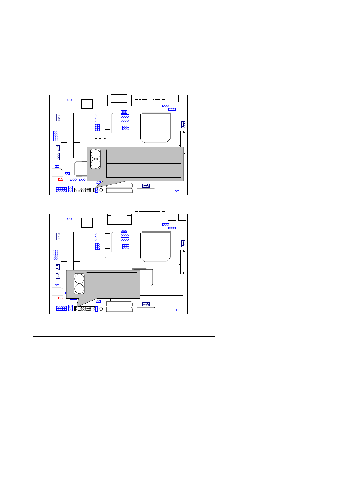
JP5 / JP23 : Set System Bus Speed (See Figure-1)
JP23
JP5
1-2 Auto
1-2 Auto
AC97
1
2-3 66/100
1
2-3 66
AU
8810
1
1
133
100/133
INTEL CPU CLK SET
1
JP5 JP23
Auto 1-2 1-2
66 2-3 2-3
CPU
1
100 NC 2-3
133 NC NC
GMCH/
82810/
810E
FWH32
ICH/
82801
6WMMC7
Figure-1
Note: JP23 is only available when th e motherboard use 82810E
chipset.
2
Page 5
6WMMC7 Series
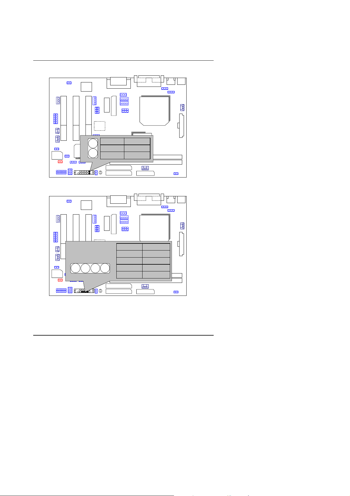
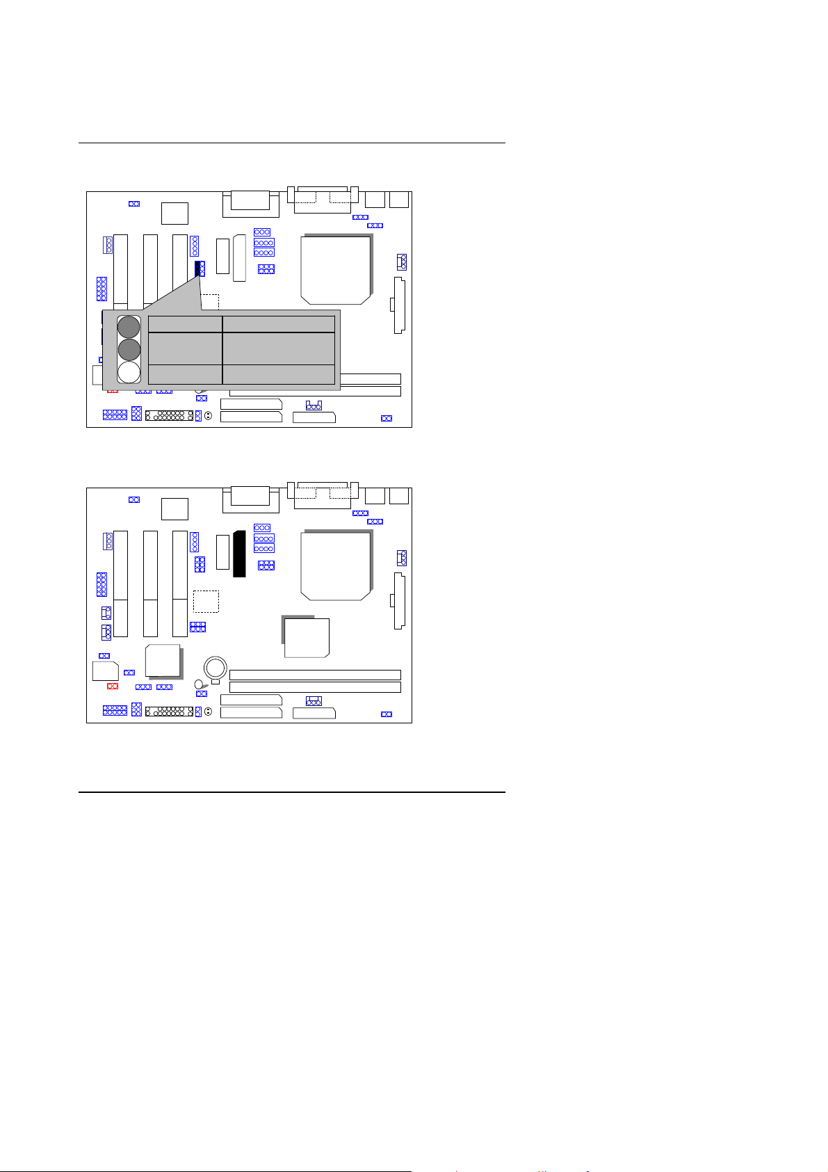
II. Jumper Setting :
GN : Green Function Switch
FWH32
GD : Green Function LED
ICH/
82801
AC97
AC97
AU
8810
CPU
PIN No. Function
Open Normal Operation
6WMMC7
GMCH/
82810 /
810E
Short Entering Green
Mode
CPU
AU
8810
GMCH/
82810
810E
FWH32
1
PIN No. Function
−−−−
ICH/
82801
+
6WMMC7
1 LED +
2
LED −
3
Page 6
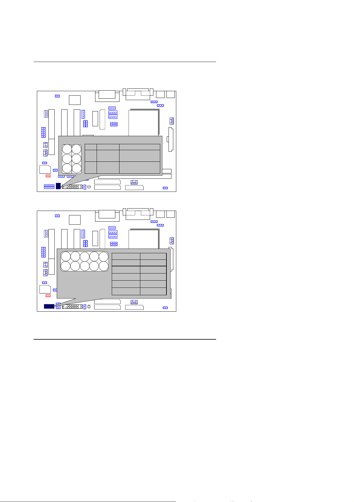
HD : IDE Hard Disk Active LED
AC97
AU
8810
Quick Installation Guide
CPU
FWH32
ICH/
82801
1
PIN No. Function
+
6WMMC7
1 LED +
−−−−
2
SPKR: External Speaker Connector
FWH32
AC97
External Speaker
ICH/
1
+
82801
AU
8810
6WMMC7
PIN No. Function
GMCH/
LED −
CPU
1 VCC
GMCH/
2 NC
3 NC
4 Data
4
Page 7

6WMMC7 Series
J9: Buzzer Enabl e (Opti onal)
AC97
PIN No. Function
ICH/
FWH32
RES : Reset Switch
82801
AC97
PIN No. Function
Open Normal
Operation
Short Reset Hardware
ICH/
System
FWH32
82801
CPU
AU
8810
Open Internal Buzzer Disable
6WMMC7
Close Internal Buzzer Enable
AU
8810
6WMMC7
GMCH/
GMCH/
82810
/810E
CPU
5
Page 8

Quick Installation Guide
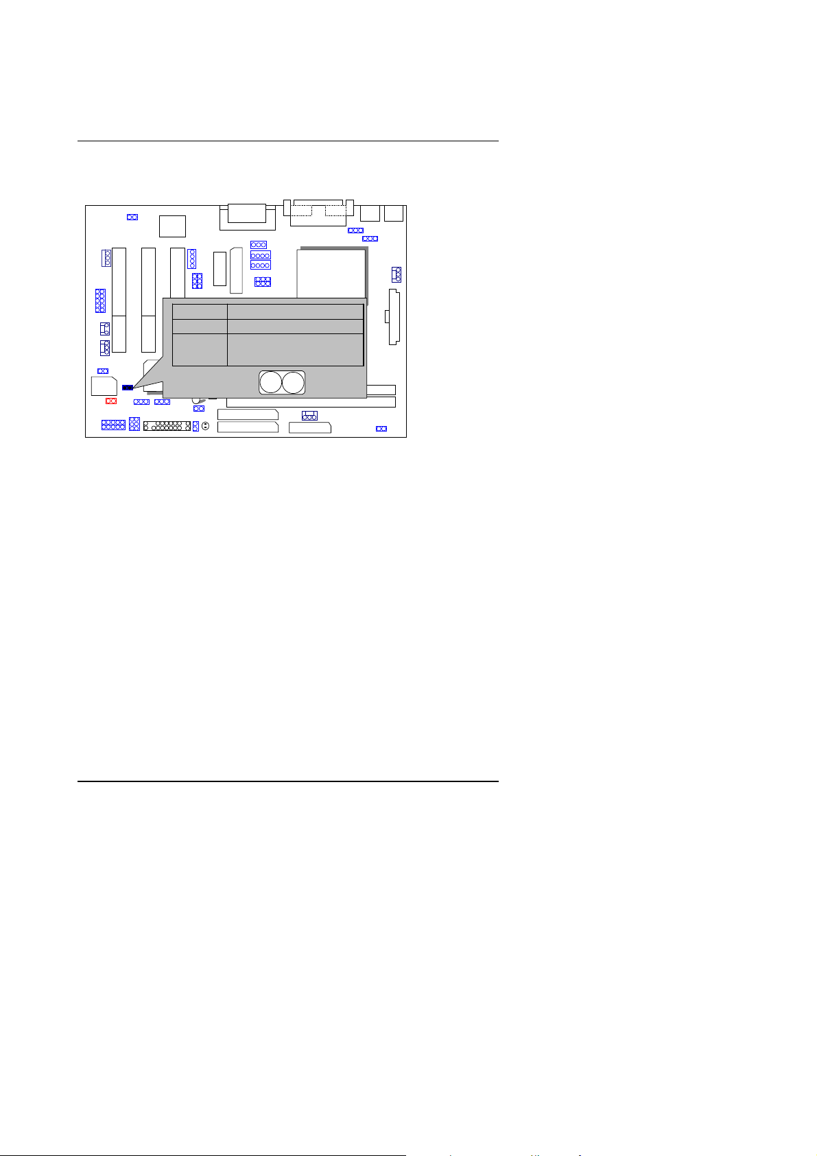
PWR : Power LED Connector (as 3 steps ACPI LED)
FWH32
AC97
CPU
AU
−−−− −−−−
8810
PIN No. Function
1 LED +
6WMMC7
2
LED −
3
LED −
GMCH/
+
ICH/
82801
PW : Soft Power Co nnector
FWH32
AC97
AU
8810
PIN No. Function
Open Normal operation
ICH/
Short Soft On/Off
82801
CPU
GMCH/
6WMMC7
6
Page 9
6WMMC7 Series
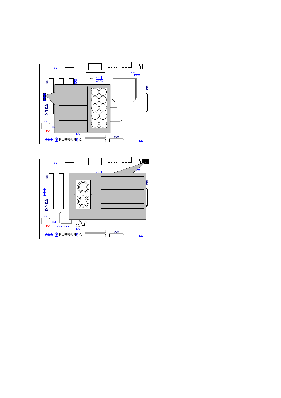
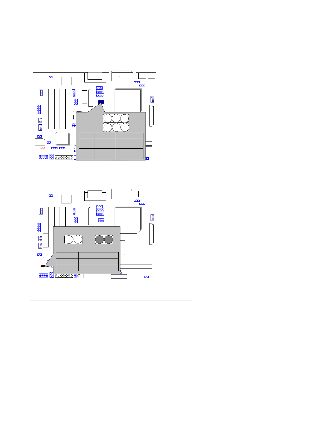
IR : Infrared Connector (IR / CIR)
FWH32
PS/2 Mouse / Keyboard Connector
FWH32
AC97
PIN
Function
No.
1
2 NC
3 IRRX
4 GND
5 IRTX
6 NC
7 CIRRX
ICH/
8 VCC
82801
9 NC
10 NC
AC97
6
4
ICH/
PS/2 Keyboard
82801
VCC
AU
8810
6WMMC7
PS/2 Mouse
AU
8810
2
6WMMC7
1
5
5
3
1
GMCH/
82810/
810E
CPU
6
10
PS/2 Mouse/ Keyboard
Pin No. Function
CPU
1 Data
2 NC
3 GND
4 VCC(+5V)
5 Clock
GMCH/
6 NC
7
Page 10
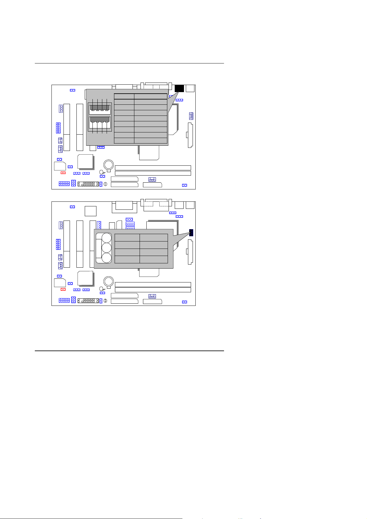
USB : USB Port
FWH32
ICH/
82801
AC97
6 5
1 2
8
7
PIN No. Function
1 USB V0
2 USB D03 USB D0+
4 GND
5 USB V1
6 USB D17 USB D1+
4
8 GND
6WMMC7
3
AU
8810
GMCH/
82810/
810E
Quick Installation Guide
CPU
CPU FAN : CPU Cooling Fan Power Connector
FWH32
ICH/
82801
AC97
PIN No. Function
AU
8810
1
1 GND
2 +12V
3 SENSE
6WMMC7
GMCH/
82810/
810E
CPU
8
Page 11

6WMMC7 Series
POWER FAN : Power Cooling Fan Power Connector
FWH32
ICH/
82801
AC97
AU
8810
6WMMC7
CPU
PIN No. Function
1 GND
1
GMCH/
2 +12V
3 SENSE
SYSTEM FAN : System Cooling Fan Power Connector
FWH32
AC97
CPU
1
ICH/
82801
AU
8810
PIN No. Function
1 GND
6WMMC7
2 +12V
3 SENSE
GMCH/
82810/
810E
9
Page 12
IDE1: Primary IDE Port
FWH32
ICH/
82801
AC97
AU
8810
6WMMC7
GMCH/
82810/
810E
Quick Installation Guide
CPU
IDE2: Secondary IDE Port
FWH32
ICH/
82801
AC97
AU
8810
6WMMC7
1
1
10
GMCH/
82810/
810E
CPU
Page 13
6WMMC7 Series
FLOPPY : Floppy Port
FWH32
ICH/
82801
AC97
AU
8810
6WMMC7
GMCH/
82810/
810E
CPU
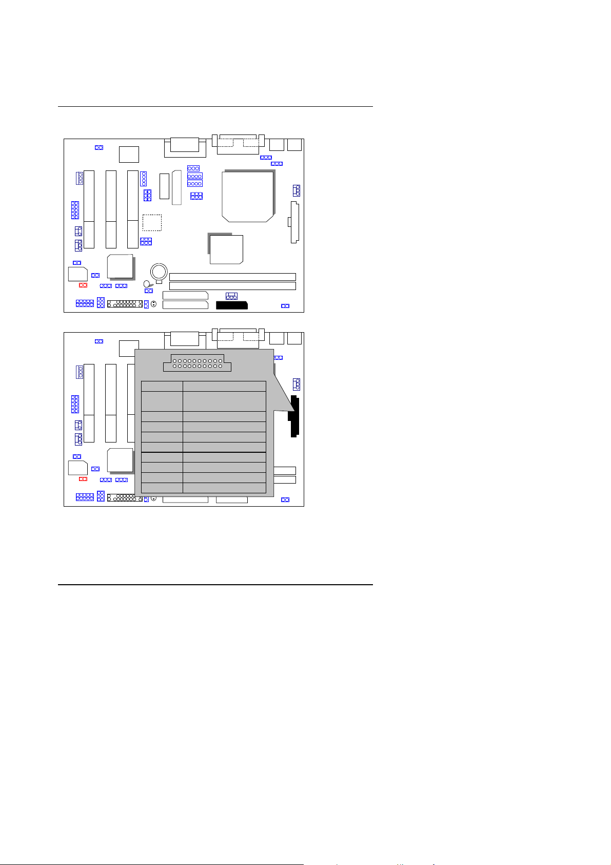
ATX POWER : ATX Power Connector
AC97
1
11
Pin No. Function
FWH32
3,5,7,13,
15-17
AU
8810
1,2,11 3.3V
4,6,19,20 VCC
10 +12V
12 -12V
ICH/
18 -5V
82801
8 Power Good
6WMMC7
GND
GMCH/
82810/
810E
9 5V SB stand by+5V
14 PS-ON(Soft On/Off)
11
1
CPU
Page 14
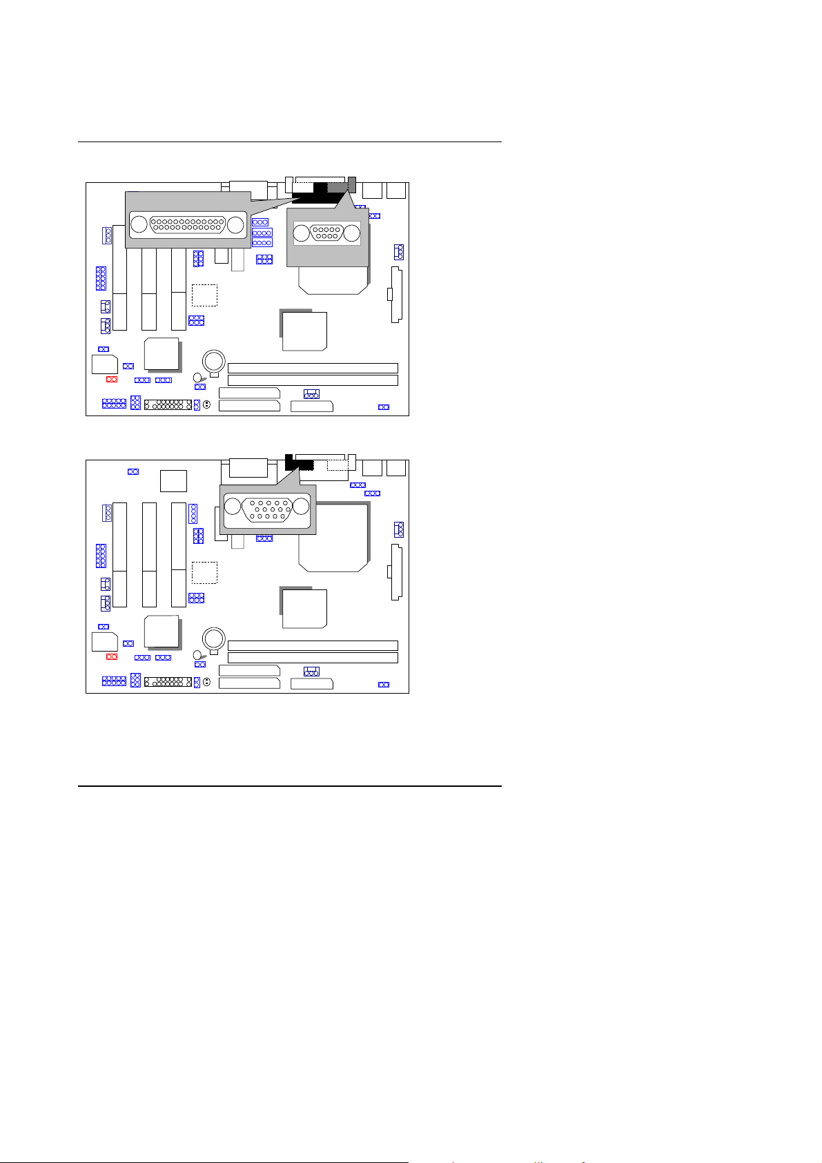
COM A / LPT Port
AC97
LPT PORT
ICH/
FWH32
82801
VGA : VGA Port
AC97
AU
8810
6WMMC7
Quick Installation Guide
COM A
CPU
GMCH/
82810/
810E
CPU
AU
8810
GMCH/
82810/
810E
FWH32
ICH/
82801
6WMMC7
12
Page 15
6WMMC7 Series
JP12:Clear CMOS Function
AC97
3 2 1
AU
8810
PIN No. Function
1-2 close Clear CMOS
ICH/
FWH32
JP2: PS/2 Keyboard Power On Selection
82801
AC97
PIN No. Function
ICH/
FWH32
82801
6WMMC7
2-3 close Normal (Default)
AU
8810
1-2
close
2-3
close
PS/2 Keyboard Power
on Enabled
PS/2 Keyboard Power
6WMMC7
on Disabled (Default)
GMCH/
1 2 3
GMCH/
82810/
810E
CPU
CPU
13
Page 16
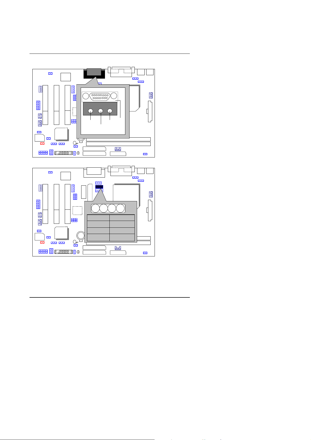
J8:Game & Audio Port
FWH32
ICH/
82801
AC97
AU
8810
Line Out
6WMMC7
Line In
MIC
GAME
GMCH/
82810/
810E
Quick Installation Guide
CPU
J7:CD Audio Line In
FWH32
ICH/
82801
AC97
AU
8810
PIN No. Function
6WMMC7
1 CD_L
2,3 GND
4 CD_R
14
GMCH/
82810/
810E
CPU
1
Page 17

6WMMC7 Series
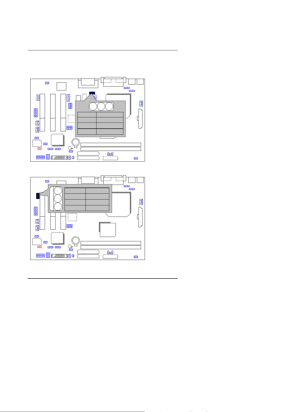
JP11:AUX_IN
FWH32
JP3 TEL :The connector is for Modem with internal voic e c onnector.
ICH/
82801
AC97
AC97
AU
8810
6WMMC7
JP11
1
PIN No. Function
1 AUX_L
CPU
2,3 GND
4 AUX_R
GMCH/
82810/
810E
1
GMCH/
82810/
810E
CPU
TEL
FWH32
ICH/
82801
AU
8810
PIN No. Function
6WMMC7
1 Phone-in
2,3 GND
4 Mono-out
15
Page 18
Quick Installation Guide
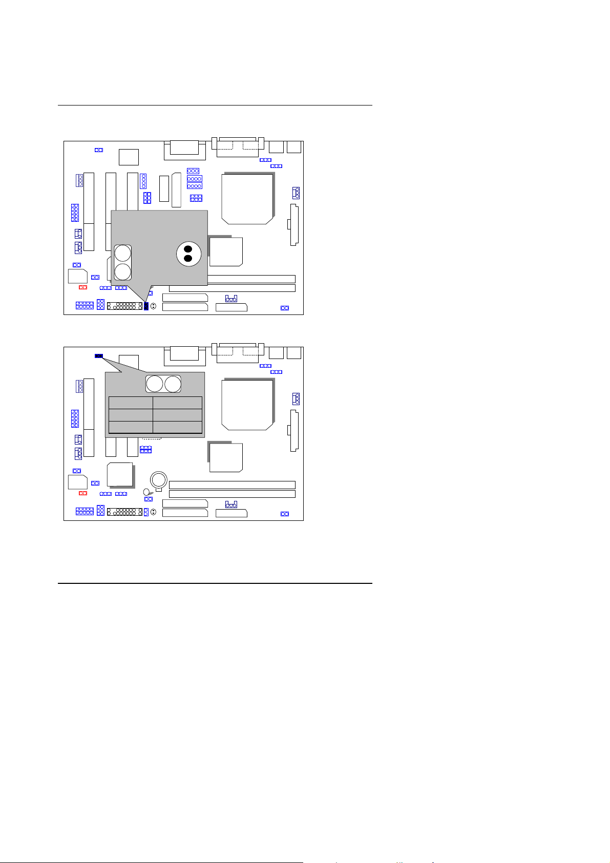
JP18 SPDIF:(Optional for the SPDIF output is capab le of providing
digital audio to external speakers or compressed AC3 data to an
external Dobly Digital decoder.)
AC97
ICH/
FWH32
82801
J14 : Wake on LA N
AC97
1
PIN No. Function
2
3
ICH/
FWH32
82801
1
PIN No. Function
AU
8810
1 VCC
2 SPDIF OUT
3 GND
6WMMC7
1 +5V SB
2 GND
3 Signal
AU
8810
6WMMC7
GMCH/
82810/
810E
GMCH/
82810/
810E
CPU
CPU
16
Page 19

6WMMC7 Series
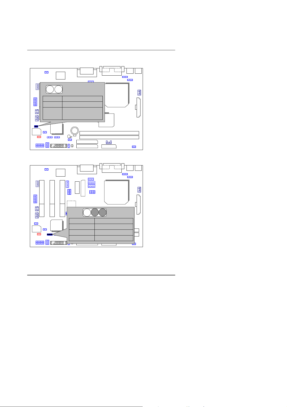
J17 RING PWR ON: Internal Modem Card Ring Pwr On
FWH32
JP1 : STR Function
(If you want to use STR Function, pl e ase set jumpe r JP1 Close d.)
82801
AC97
AU
8810
PIN No. Function
1 Signal
6WMMC7
ICH/
1
AC97
2 GND
GMCH/
82810/
810E
CPU
CPU
AU
8810
FWH32
6WMMC7
PIN No. Function
ICH/
82801
Close STR Enable
GMCH/
82810/
810E
1
Open STR Disable(Default)
17
Page 20
JP10 : STR LED Connector & DIMM LED
FWH32
AC97
STR LED Connector
External.
ICH/
82801
1
JP10
AU
8810
6WMMC7
DIMM LED
GMCH/
+
82810/
810E
JP14 : Case Op en
AC97
JP14
1
PIN No. Function
1 Signal
AU
2 GND
8810
Quick Installation Guide
CPU
CPU
GMCH/
82810/
810E
FWH32
ICH/
82801
6WMMC7
18
Page 21
6WMMC7 Series
JP16: Top Block Lock
AC97
PIN No. Function
Open Top Block Lock
Close Top Block Unlock
AU
8810
(Default)
6WMMC7
FWH32
ICH/
82801
JP13 :Safe mode/Recovery/Normal
FWH32
ICH/
82801
AC97
AU
8810
6WMMC7
PIN No. Function
1-2close Normal (Default)
2-3close Safe mode
1-2-3open Recovery
GMCH/
82810/
810E
1
GMCH/
82810/
810E
CPU
CPU
19
Page 22
JP17: Onboard Sound Function (Optional)
1
FWH32
AC97
CPU
AU
8810
PIN No. Function
1-2close Enabled Sound
ICH/
82801
2-3close Disabled Sound
6WMMC7
(Default)
GMCH/
82810/
810E
TV/DFP :TV-Out / Digital Flat Panel Daughter Card
Connector(Optional).
AC97
1
Quick Installation Guide
CPU
AU
8810
GMCH/
82810/
810E
FWH32
ICH/
82801
6WMMC7
20
Page 23
6WMMC7 Series
J13/J20 : USB Port Selection (Optional)
AC97
CPU
AU
8810
PIN No. Function
J13
6WMMC7
J20
J13
J20
1-2close
1-2close
2-3close
2-3close
Front Panel USB
GMCH/
Enable
Back Panel USB
Enable
FWH32
J13 J20
1 1
ICH/
82801
J19 : Front Panel USB Port (Optional)
FWH32
9
10
ICH/
82801
AC97
AU
8810
6WMMC7
PIN No. Function
1
1,4,5,10 NC
2
2 +5V
GMCH/
82810/
3,7,9 GND
6 USBP0+
8 USBP0-
CPU
810E
21
Page 24
JP15: Timeout Reboot Function
FWH32
AC97
AU
PIN No. Function
8810
Open Timeout Reboot
Close No Reboot on Timeout
(Default)
ICH/
82801
6WMMC7
JP15
GMCH/
82810/
1
JP19: USB Device Wake-up Function
Quick Installation Guide
CPU
810E
22
Page 25

6WMMC7 Series
(If you want to use “
FWH32
function, you have to set the BIOS setting “USB KB/Mouse Wake
from S3” enabled, and the jumper “
*(Power on the computer and as soon as memory counting
starts, press <Del>. You will enter BIOS Setup. Select the
item “
KB/Mouse Wake from S3: Enabled
the setting by pressing "ESC" and choose the “SAVE & EXIT
SETUP” option.)
JP22 : AMR Function Select (Optional )
AC97
PIN No. Function
1-2 close Disable USB Device
AU
2-3 close Enable USB Device
8810
JP19
ICH/
82801
POWER MANAGEMENT SETUP
AC97
6WMMC7
USB KB/Mouse Wake from S3
JP19
”. Remember to save
CPU
Wake-up (Default)
Wake-up
GMCH/
” enabled).
”, then select “
1
”
USB
FWH32
JP22
CPU
AU
8810
PIN No. Onboard
AMR Card
CODEC
1-2 close Prim ary Secondary
1
ICH/
82801
Note:
If you use software audio(onboard CODEC on ly) ,
your modem riser must be “Secondary”.
If you don’t use onboard software audio, your
audio/modem riser must be “Primary”.
6WMMC7
2-3 close D isabled Primary
GMCH/
(Default)
23
Page 26
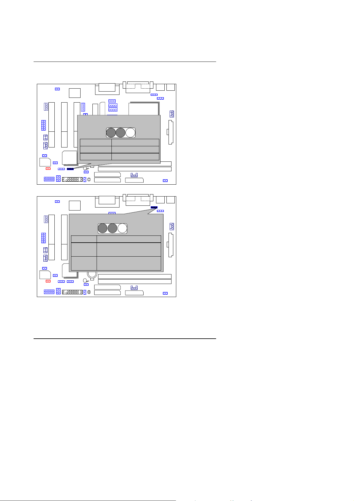
JP20/JP21:Quad Speaker (Optional)
FWH32
ICH/
82801
AC97
AU
8810
JP20
JP21
6WMMC7
PIN No. Function
JP20
1-2close
JP21
1-2close
JP20
2-3close
JP21
2-3close
2 3 1
3 2 1
GMCH/
LINE_IN
QUAD OUT
JP24: FWH Write Protection
AC97
Quick Installation Guide
CPU
JP24
ICH/
PIN No. Function
FWH32
82801
Open Normal(Default)
Close Write Protection
BAT1: Bat tery
AU
8810
Open
6WMMC7
Close
24
GMCH/
82810/
810E
CPU
Page 27
6WMMC7 Series
FWH32
82801
ICH/
AC97
Danger of explosion i f battery is
incorrectly replaced.
Replace only with the same or
equivalent type recommended by the
manufacturer.
Dispose of used batteries according
AU
8810
to the manufacturer’s instructions
+
6WMMC7
GMCH/
CPU
.
25
Page 28

Quick Installation Guide
III. Top P er formance Test Setting:
The following performance data list is the testing results of some popular
benchmark testing programs.
Users have to modify the value for each item in chipset features as follo w
for top performance sett ing.
CMOS Setup Utility-Copyright( C ) 1984-1999 Award Software
Advanced Chipset Features
SDRAM CAS Lat ency Time 2 Item Help
SDRAM Cycle Time Tras/Trc 5/7
SDRAM RAS-to-CAS Delay 2
SDRAM RAS Precharge Time 2
SDRAM Buffer Strength Auto
DRAM Page Closing Policy Precharge Bank
System BIOS Cacheable Enabled
Video BIOS Cacheable Enabled
Delayed Transaction Disabled
On-Chip Video Window Size 64MB
Local Memory Frequency 100 MHz
* Onboard Display Cache Setting *
Initial Display Cache Enabled
Display Cache Timing Fast
Move Enter:Select +/-/PU/PD:Value F10:Save ESC:Exit F1:General Help
↑↓→ ←
F5:Previous Values F6:Fail-Safe Defaults F7:Optimized Defaults
*
The above settings have to modify according to different kinds of CPU,
Menu Level
SDRAM, and peripherals for your system to work properl y.
26
Page 29

6WMMC7 Series
These data are just ref erred by us ers, and th ere is no responsibi lity for different
testing data values gotten by users. (The different Hardware & Software
configuration will result in different benchmark testing r esults.)
•
CPU
•
DRAM (128x 1) MB SDRAM (SEC KM48S8030CT-GA)
•
CACHE SIZE 128 KB included in CPU
•
DISPLAY Onboard Intel C or por ation 810 G r aphics C ont ro ller H ub)
•
STORAGE Onboard IDE (IBM DTNA-371800)
•
O.S. Windows NT™ 4.0 SPK5
•
DRIVER Display Driver at 1024 x 768 x 64k colors x 75Hz .
Intel Celeron
Processor
TM
466MHz Socket 370 processor
350MHz (100x3.5)
500MHz
(66x7.5)
Winbench99 (Ver1.1)
CPU mark99
30
37.2
FPU Winmark 1880 2680
Business Disk 3380 3140
Hi-End Disk 5890 5350
Business Graphics 125 139
Hi-End Graphics 286 364
Winstone99 (Ver1.0)
Business
Hi-End 19.7 21.9
24.8
27.2
27
Page 30

Page 31

6WMMC7 Series
•
CPU Celeron 433 OC 450 (100*4.5)
•
DRAM (64x 2) MB SDRAM (MITSUBISHI M2V64S40BTP)
•
STORAGE Onboard IDE (IBM DJNA-352030) (ATA66 )
Windows98 SE2 English Ver(FAT32), Di rectX 6.1, Driver 4.11.01
1185 PV 1.1 1024*768*16 bit (75Hz)
Motherboard 6WMMC7 6WMMC7-1
ICH
GMCH
WINBENCH 99
CPU mark32 878 878
FPU Winmark 2410 2400
Business Disk 4010 4010
Hi-End Disk 14100 14100
Business Graphics 141 145
Hi-End Graphics 392 394
3D WINBENCH 99
3D WINMARK
Final Reality
AGP 137.09
OVERALL 4.17
3D MARK99 Max
3D MARKS 2811
CPU 3DMARK 4229
WINDOWS NT4.0+ SPK5 4.11.01.1185 PV1.1
1024*768 65536 colors(75Hz )
WINSTONE 99
BUSINESS 27.7
HI-END 22.9
82801AA
82810DC100
386 292
82801AA
82810
134.52
3.99
2298
4271
26.6
22.1
27
Page 32

IV. Suspend to RAM Installation
Suspend to RAM Installation
A.1 Introduce STR function:
Suspend-to-RAM (STR) is a Windows 98 ACPI sleep mode function. When
recovering from STR (S3) sleep mode, the system is able, in just a few
seconds, to retrieve the la st “state” of the system before it went to sleep and
recover to that state. T he “state” is stored in memory (RAM) before the
system goes to sleep. During STR sleep mode, your system uses only
enough energy to maintain crit ical information and system functions,
primarily the system state and t he abil ity to recognize various “wake up”
triggers or signals, respectively.
A.2 STR function installa tion
Please use the following ste ps to complete the STR function installation.
Step-By-Step Setup
Step 1:
To utilize the STR function, the system must be in Windows 98 ACPI mode.
Putting Windows 98 into ACPI mode is fairly easy.
A. Insert the Windows 98 CD into your C D-ROM drive, select Start, and th en
Run.
B. Type (without quotes)
enter key or click OK.
(All the bios version dated 12/01/99 or later are ACPI compatib le.
Just type" D: \Se tup", the opera ting sy stem will be installed as ACPI
mode.)
C. After setup completes, remove the CD, and reboot your system
(This manual assumes that your CD-ROM device drive letter is D:).
“D:\setup /p j”
in the window provided. Hit the
28
Page 33

6WMMC7 Series
Step 2:
(If you want to use STR function, ple ase set jumpe r JP1 Close d.)
FWH32
Step 3:
Power on the computer and as soon as memory countin g starts, press <Del>.
You will enter BIOS Setup. Select the item
SETUP”,
Remember to save the settings by pressing "ESC" and choose the
EXIT SETUP”
Congratulation! You have completed the installatio n and now can use the STR
function.
AC97
AU
8810
ICH/
82801
then select
option.
CPU
PIN No. Function
6WMMC7
1
GMCH/
82810/
810E
Close STR Enable
Open STR Disable
“POWER MANAGEMENT
“ACPI Suspend Type: S3 (Suspend to RAM)”
“SAVE &
.
29
Page 34

Suspend to RAM Installation
A.3 How to put your system into STR mode?
There are two ways to accomplish this:
1. Choose the “Stand by” item in the “Shut Down Windows” area.
A. Press the “Start” button and then select “Shut Down”
B. Choose the “Stand by” item and press “OK”
30
Page 35

6WMMC7 Series
2. Define the sys tem ”power on” button to initiate STR sleep mode:
A. Double click “My Computer” and then “Control Panel”
B. Double click the “ Power Management” item.
31
Page 36

Suspend to RAM Installation
C. Select the “Advanced” tab and “Standby” mode in Power Buttons.
Step 4:
Restart your computer to complete setup.
Now when you want to enter STR sleep mode, just momentarily press the
“Power on” button..
A.4 How to recover from the STR sleep mode?
There are seven ways to “wake up” the sy stem:
1. Press the “Power O n” button.
2. Use the “Keyboard Power On” function.
3. Use the “Mouse Power On” function.
4. Use the “Resume by Alarm” function.
5. Use the “Modem Ring On” function.
6. Use the “Wake On LAN” function.
7. Use the “USB Device Wake Up” function.
32
Page 37

6WMMC7 Series
A.5 Notices :
1. In order for STR to function properly, several hardware and software
requirements must be satisfied:
A. Your ATX power supply must comply with the ATX 2.01 specification
(provide more than 720 mA 5V Stand-By current).
B. Your SDRAM must be PC-100 compliant.
2. Jumper JP10 is provided to connect to the STR LED in your system
chassis. [Your chassis may not provide this feature.] The DIMM LED will
be illuminated when your syst em is in STR sleep mode.
FWH32
AC97
STR LED Connector
External.
ICH/
82801
1
JP10
AU
8810
6WMMC7
DIMM LED
+
GMCH/
82810/
810E
CPU
33
Page 38

Page 39

Table of Contents
TABLE OF CONTENTS
1. INTRODUCTION
1.1. PREFACE ..................................................................................................... 1-1
1.2. KEY FEATURES ........................................................................................... 1-1
1.3. PERFORMANCE LIST .................................................................................. 1-2
1.4. BLOCK DIAGRAM......................................................................................... 1-4
TM
1.5. INTRODUCE THE INTELCeleron
1.6. INTRODUCE AMR .......... .. ... ............... .. .. .. .. ............... .. .. ... ................ ... .. .. .. ... 1-5
2. SPECIFICATION
2.1. HARDWARE ................................................................................................. 2-1
2.2. SOFTWARE.................................................................................................. 2-2
2.3. ENVIRONMENT............................................................................................ 2-2
3. HARDWARE INSTALLATION
3.1. UNPACKING ................................................................................................. 3-1
3.2. MAIN BOARD LAYOUT................................................................................. 3-2
3.3. QUICK REFERENCE FOR JUMPERS & CONNECTORS........ .. .. ................ . 3-3
Socket 370 Processor........................ 1-5
3.4. DRAM INSTALLATION.................................................................................. 3-8
3.5. CPU SPEED SETUP.....................................................................................3-9
3.6. CMOS RTC & ISA CFG CMOS RAM............................................................. 3-10
3.7. SPEAKER CONNECTOR INSTALLATION................ .................................... 3-10
3.8. HARDWARE RESET SWITCH CONNECTOR INSTALLATION.......... .. ... .. .. . 3-10
3.9. POWER LED CONNECTOR INSTALLATION............................................... 3-10
3.10. IDE & ATAPI DEVICE INSTALLATIO N .. .. .. ............... .. ............... .. ............... 3-10
3.11. PERIPHERAL DEVICE INSTALLATION...................................................... 3-11
3.12. KEYBOARD & PS/2 MOUSE INSTALLATION ............ ... .. .. .. .. .. ... .............. .. 3-11
1
Page 40

6WMMC7 Series
4. BIOS CONFIGURATION
4.1. ENTERING SETUP................... .. .. .. ............... .. .. ... ............... .. .. .. .. ............... .. 4-1
4.2. CONTROL KEYS .... .. .. .. .. ... .. .. .. .. .. ... .. .. .. .. .. .. ............... .. ... .. .... .. ............... .. .. .. . 4-1
4.3. GETTING HELP ............................................................................................ 4-2
4.3.1. Main Menu ......................................................................................... 4-2
4.3.2. Status Page Setup Menu / Option Page Setup Menu......................... 4-2
4.4. THE MAIN MENU.......... .. ... .. .. .. .. .. ... .. .. ............... .. .. .. ................. .. .. .. ... ........... 4-2
4.5. STANDARD CMOS FEATURES MENU ........................................................ 4-5
4.6. ADVANCED BIOS FEATURES .................................................................... 4-9
4.7. ADVANCED CHIPSET FEATURES ............................................................. 4-14
4.8. INTEGRATED PERIPHERALS...................................................................... 4-17
4.9. POWER MANAGEMENT SETUP.................................................................. 4-24
4.10. PNP/PCI CONFIGURATIONS ..................................................................... 4-29
4.11. PC HEALTH STATUS. ................................................................................ 4-31
4.12. FREQUENCY/VOLTAGE CONTROL .......................................................... 4-33
4.13. LOAD FAIL-SAFE DEFAULTS.................................................................... 4-35
4.14. LOAD OPTIMIZED DEFAULTS...... .. .. .. ... .. ............... .. .. .. ............... .. .. .......... 4-36
4.15. SET SUUPERVISOR/USER PASSWORD.................................................. 4-37
4.16. SAVE & EXIT SETUP .. .. .. .. ............... .. ... ................ ... .. .. ............... .. .. ............ 4-38
4.17. EXIT WITHOUT SAVING ............................................................................ 4-39
APPENDIX :
A.Onboard Driver Inst all ation Procedure..................................................A-1
B.BIOS Flash Procedure .......................... ...............................................B-1
C.AU8810 Driver Installation ...................................................................C-1
2
Page 41

Introduction
1. INTRODUCTION
1.1. PREFACE
Welcome to use the
It is a Socket 370 processor based PC / AT compatible system with PCI Bus,
and has been designed to be th e f astest P C / AT syst em. T here ar e some new
features allow you to operate the system with just the performance you want.
This manual also explains how to install the motherboard for operation, and
how to set up your CMOS Configuration with BIOS Setup program.
6WMMC7 Series(6WMMC7 / 6WMMC7-1)
motherboard.
1.2. KEY FEATURES
Socket 370 Processor based PC / AT compatible main board.
Socket 370 Pins ZIF white socket on board.
Built-in AC 97-Link softwa re audio.
Aureal AU8810 Hardware audio (Optional).
Supports Socket 370 processor.
INTEL FW82810 / 810E chipset, Supports SDRAM / Ultra ATA66 / DMA33
IDE / Keyboard and PS/2 Mouse Power On / ACPI features.
Supports 2xDIMMs using 3.3V SDRAM DIMM module.
Supports 4MB SDRAM Display cache (Optional).
Supports external M odem Ring-On on COMA and internal Mod em Ring-On.
Supports PC100 SDRAM 16MB~512MB memory on board.
Supports Wake-up on LAN.
Supports Suspend To RAM Function.
Supports AMR Interface.
Supports feature connector for TV-Out or DFP (Digital Flat Panel)
(Optional).
3xPCI Bus slots.
Supports 2 channels Ultra ATA66/DMA33 IDE ports for 4 IDE Devices.
Supports 1x Line in, 1x Li ne Out , 1x Mic in, 1x CD Line in,1x GA M E Port 1
x TEL, 1x A UX in, 1x SPDIF OU T (Optional).
Supports 1xCOM (16550), 1xLPT (EPP / ECP/ SPP), 1x1.44MB Floppy
port.
Supports 2XUSB port & PS/2 Mouse/ Keyboard port.
Licensed AWARD BIOS, 4M bits Flash ROM .
24.3 cm x 19 cm Micro ATX size form factor, 4 layers PCB.
1-1
Page 42

6WMMC7 Series
1.3. PERFORMANCE LIST
The following performance data list is the testing results of some popular
benchmark testing programs.
These data are just referr ed by users, and there is no responsibility for differen t
testing data values gotten by users. (The different Hardware & Software
configuration will result in different benchmark testing results.)
•
CPU
•
DRAM (128x 1) MB SDRAM (SEC KM48S8030CT-GA)
•
CACHE SIZE 128 KB included in CPU
•
DISPLAY Onboard Intel Corporat ion 810 G raphics Control ler Hub)
•
STORAGE Onboard IDE (IBM DTNA-371800)
•
O.S. Windows NT™ 4.0 SPK5
•
DRIVER Display Driver at 1024 x 768 x 64k colors x 75Hz .
Intel Celeron
TM
466MHz Socket 370 processor
Processor
350MHz (100x3.5)
Winbench99 (Ver1.1)
CPU mark99
30
FPU Winmark 1880 2680
Business Disk 3380 3140
Hi-End Disk 5890 5350
Business Graphics 125 139
Hi-End Graphics 286 364
Winstone99 (Ver1.0)
Business
24.8
Hi-End 19.7 21.9
1-2
500MHz
(66x7.5)
37.2
27.2
Page 43

Introduction
•
CPU Celeron 433 OC 450 (100*4.5)
•
DRAM (64x 2) MB SDRAM (MITSUBISHI M2V64S40BTP)
•
STORAGE Onboard IDE (IBM DJNA-352030) (ATA66 )
Windows98 SE2 English Ver(FAT32), Di rec t X 6.1, Driver 4.11.01
1185 PV 1.1 1024*768*16 bit (75Hz)
Motherboard 6WMMC7 6WMMC7-1
ICH
GMCH
82801AA
82810DC100
WINBENCH 99
CPU mark32 878 878
FPU Winmark 2410 2400
Business Disk 4010 4010
Hi-End Disk 14100 14100
Business Graphics 141 145
Hi-End Graphics 392 394
3D WINBENCH 99
3D WINMARK
386 292
Final Reality
AGP 137.09
OVERALL 4.17
3D MARK99 Max
3D MARKS 2811
CPU 3DMARK 4229
WINDOWS NT4.0+ SPK5 4.11.01.1185 PV1.1
1024*768 65536 colors(75Hz )
WINSTONE 99
BUSINESS 27.7
HI-END 22.9
82801AA
82810
134.52
3.99
2298
4271
26.6
22.1
1-3
Page 44

6WMMC7 Series
836
1.4. BLOCK DIAGRAM
Display
AGP
DFP
Display Cache
SDRAM
ATA66 IDE Channels
COM Port
LPT Port
SDRAM
2 USB Ports
Winbond
W
IR/CIR
PS/2
Socket 370
CPU
Host Bus 66/100/133MHz
GMCH
82810
82810DC100
82810E
ICH
82801AA
FWH
Game
Port
27
Floppy
Hub
Interface
66/100/133 MHz
66/100/133 MHz
3.3V SDRAM
14.318/33/48/66 MHz
PCI Bus 33MHz
AU8810
AC’97 Link
CODEC
MIC
AMR
100 MHz
Line
Line In
Out
ICS
9248-96
3 PCI
1-4
Page 45

1.5. INTRODUCE THE INTEL
Figure 1: INTEL CeleronTM Socket370 Pr ocessor
1.6 INTRODUCE AMR
Celeron
Introduction
TM
Socket 370 Processor
The Audio Modem Riser (AMR) is a new port that supports both audio and
modem. The main purpose of t he AMR port is to provide lower cost and high er
levels of integration at all levels of the PC platform.
The backbone of the AMR int erface is on AC ’97 compliant AC-Li nk with support
for codes. Motherboard support for an AMR interface are not only capable of
achieving the lowest possible cost for basic PC audio and modem, but have
also introduced increased motherboard flexibility enabling robust, cost
effective scalability.
The AMR is done thr ough software and controlled by the motherboard’s I/O
Controller Hub (ICH). Ther e are two t ypes of AM R , one defined as primary and
another defined as secondary. If the motherboard with onboard sound Aureal
AU8810, the AM R must be used primary.
1-5
Page 46

Page 47

6WMMC7 Series
2. SPECIFICATION
2.1. HARDWARE
•
CPU
•
PROTECTION
•
SPEED
•
DRAM MEMORY
•
CACHE MEMORY
•
I/O BUS SLOTS
•
IDE PORTS
•
I/O PORTS
•
DISPLAY CACHE
−
Socket 370 processor.
−
66/100/133 MHz So cket 370 on board.
−
Speaker Alarm when detect "CPU FAN Failure" or
“CPU Overheat”.
−
Automatically slow down CPU speed when "CPU
Overheat".
−
H/W monitor power status (±5V, ±12V, VGTL,5VSB,
CPU voltage & CMOS battery voltage).
−
66/100/133 MHz sy stem speed.
−
33 MHz PCI-Bus speed.
−
2 banks 168 pins DIMM module sockets on board.
−
Use 16 / 32 / 64 / 128 / 256MB DIMM module DRAM .
−
Supports PC-100 SDRAM 16MB~512 MB.
−
32 KB 1st cache memory included in CPU.
−
L2 cache memory included in CPU.
(Depend On CPU type)
−
Supports DIB speed mode for L2 Cache.
−
3 33MHz Master / Slave PCI-BUS.
−
2 Ultra ATA66/DMA33 Bus Master IDE channels on
board.(Using IRQ14,15)
−
Supports Mode 3,4 IDE & ATAPI CD – ROM.
−
Supports 1 16550 COM ports.
−
Supports 1 SPP/EPP/ECP LPT port.
−
Supports 1 1.44/2.88 MB Floppy port.
−
Supports 2 USB ports.
−
Supports PS/2 Mouse & Keyboard.
−
4MB SDRAM Display cache (Optional).
2-1
Page 48

•
Audio Ports
•
GREEN FUNCTION
•
BIOS
•
DIMENSION
2.2. SOFTWARE
•
DRIVER
•
BIOS
•
O.S.
2.3. ENVIRONMENT
•
Ambient Temp.
•
Relative Hum.
•
Altitude
•
Vibration
•
Electricity
Specification
−
1x Line in
−
1x Line out
−
1x Mic in
−
1x Game Port
−
1x CD Line in
−
1x TEL
−
1x SPDIF Out (Optional)
−
1x AUX In.
−
Suspend mode support.
−
Green switch & ACPI LED support.
−
IDE & Display power down support.
−
Monitors all IRQ / DMA / Display / I/O events.
−
Supports Plug & Play, DMI Function.
−
Micro ATX Form Factor, 4 layers PCB.
−
IUCD (Bus Master + Sound Driver + LDCM + Utility)
−
INTEL 82810 Driver.
−
Licensed AWARD BIOS.
−
AT CMOS Setup, BIOS / Chipset Setup, Green
Setup, Hard Disk Utility incl uded.
−
Operation with MS-DOS, Windows95,
Windows98, WINDOWS NT, OS/2, NOVELL and
SCO UNIX.
−
0°C to +50°C (Operating).
−
0 to +85% (Operating).
−
0 to 10,000 feet (Operating).
−
0 to 1,000 Hz.
−
4.75 V to 5.25 V. (Max. 20A current at 5V.)
2-2
Page 49

6WMMC7 Series
3. HARDWARE INSTALLATION
3.1. UNPACKING
The main board package should contain the following:
6WMMC7 Series ( 6WMMC7/6WMMC7-1)
•
The
•
USER'S MANUAL for main board.
•
Cable set for IDE, Floppy devices.
•
CD for main board Utility. [IUCD (Bus Master + Sound Driver + LDCM +
Utility), INTEL 82810 Driver.]
The main board contains sensitive electric components, which can be easily
damaged by static electricity, so the main board should be left in its original
packing until it is installed.
Unpacking and installation should be done on a grounded anti-static mat. The
operator should be wearing an anti static wristband, grounded at the same
point as the anti-static mat.
Inspect the main board carton for o bvious da mage. Shipping and handli ng may
cause damage to your board. Be sure there are no shipping and handling
damages on the board before proceeding.
main board.
After opening the main board carton, extract the system board and place it only
on a grounded anti-static sur face component side up. Again inspect the board
for damage. Press down on all of the socket IC's to make sure that they are
properly seated. Do this only on with the board placed on a firm flat surface.
DO NOT APPLY POWER TO THE BOARD IF IT HAS BEEN DAMAGED.
0000
3-1
Page 50

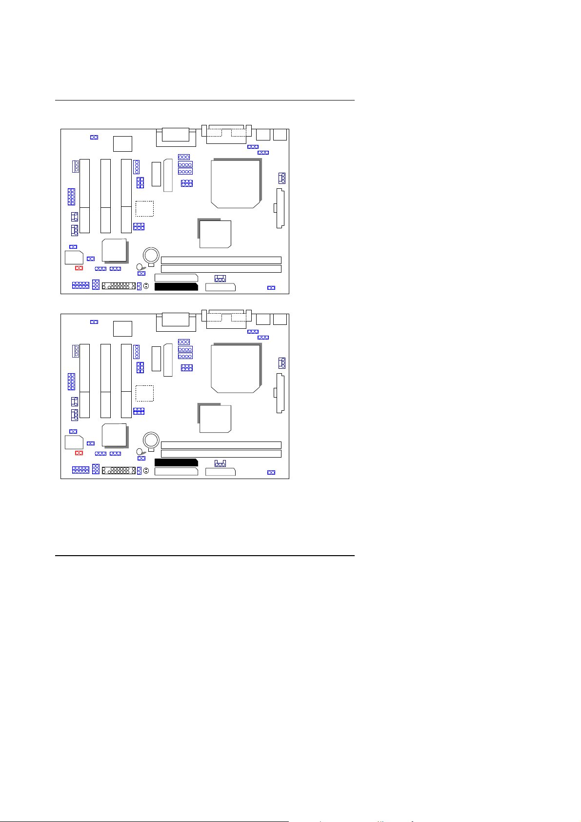
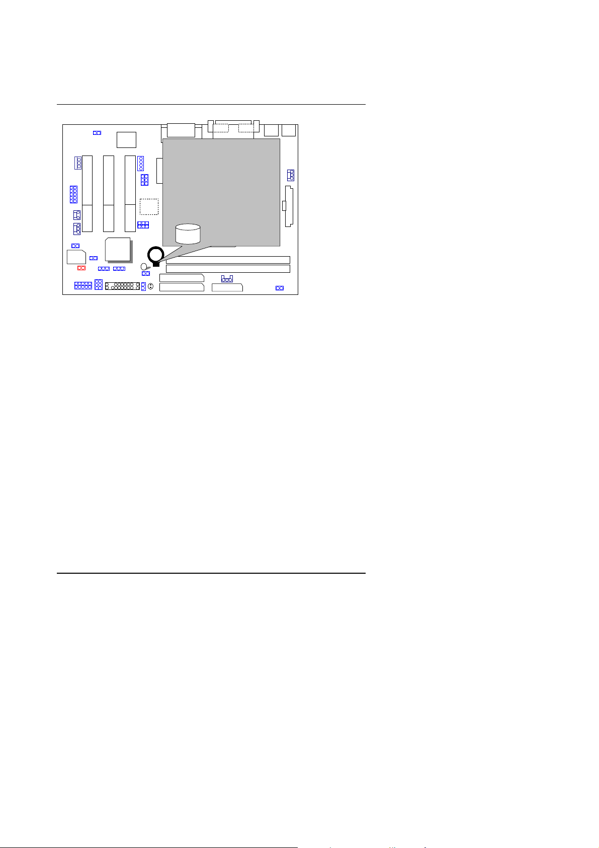
3.2. MAIN BOARD LAYOUT
Hardware Installation
6WMMC7
WOL
IR
J17
SYSTEM
FAN
FWH32
JP24
6WMMC7-1
WOL
IR
J17
SYSTEM
FAN
FWH32
JP24
JP14
JP16
J19
JP14
JP16
J19
JP15
JP13 JP12
J13
J20
JP15
JP13 JP12
J13
J20
ICH/
82801
ICH/
82801
AC97
J12
AC97
J12
JP11
JP17
JP23
JP5
JP10
JP11
JP17
JP23
JP5
JP10
AU
8810
AU
8810
JP22
JP22
AMR
BAT
J9
AMR
BAT
J9
Game &
Audio
TV/DFP
SDRAM
SDRAM
DIMM 1
DIMM 2
IDE 2
IDE 1
½
Figure 3.1¾
Game &
Audio
TV/DFP
SDRAM
SDRAM
DIMM 1
DIMM 2
IDE 2
IDE 1
½
Figure 3.2¾
JP18
J7
JP3
JP20
JP21
JP18
J7
JP3
JP20
JP21
VGA COMA
LPT
CPU
GMCH
82810
810E
DC100
Floppy
VGA COMA
LPT
6WMMC7
POWER
FAN
CPU
GMCH
82810
810E
Floppy
6WMMC7-1
POWER
FAN
JP2
JP2
CPU
FAN
ATX
PWR
JP1
CPU
FAN
ATX
PWR
JP1
PS/2 USB
JP19
PS/2 USB
JP19
3-2
Page 51

6WMMC7 Series
3.3. QUICK REFERENCE FOR JUMPERS & CONNECTORS
I/O Ports Connector
USB USB port.
IDE1 For Primary IDE port .
IDE2 For Secondary IDE por t.
PS/2 For PS/2 Mouse & Keyboard por t.
FLOPPY For Floppy port.
COMA For Serial port1 (COM A){Support Modem Ring On}.
LPT For LPT port.
VGA For VGA Port.
ATX Power For ATX Power Connector.
GAME & Audio
Socket 370
For Socket 370 Processor installed
IR : INFRARED Connector (IR / CIR)
Pin No. Function
1 VCC
2 NC
3 IRRX
4 GND
5 IRTX
6 NC
7 CIRRX
8 VCC
9 NC
10 NC
CPU FAN : CPU cooling FAN Power Connector
Pin No. Function
1 GND.
2 +12V
3 SENSE
For Game & MIC LINE-IN, LINE-OUT,TEL Port ,CD-IN,
AUX-IN, SPDIF OUT (Optional)
3-3
Page 52

PWR FAN: Power FAN Connector
Pin No. Function
1 GND.
2 +12V
3 SENSE
SYS FAN: System FAN Connector
Pin No. Function
1 GND.
2 +12V
3 SENSE
J9:Buzzer Enable (Optional)
Pin No. Function
Open Internal Buzze r Disable
Close Internal Buzzer Enable
J17 RING PWR ON :Internal Modem Card Ring PWR On
Pin No. Function
1 Signal
2 GND
JP2 : Keyboard Power On Selection
Pin No. Function
1-2 close Enabled Keyboard Power On.
2-3 close Disabled Keyboard Power On( D efault).
JP12 : Clear CMOS
Pin No. Function
1-2 close Clear CMOS
2-3 close Normal operation (Default).
J7: CD Audio Line in
Pin No. Function
1 CD_L
2,3 GND
4 CD_R
JP11:AUX_IN
Hardware Installation
3-4
Page 53

6WMMC7 Series
Pin No. Function
1 AUX_L
2,3 GND
4 AUX_R
J14:Wake on LAN
Pin No. Function
1 +5VSB
2 GND
3 Signal
JP3:TEL –The connector for Modem with internal voice connector.
Pin No. Function
1 Phone-in
2,3 GND
4 Mono-out
JP1:STR Enable
Pin No. Function
Close STR Enable
Open STR Disable (Default)
JP14: Case Open
Pin No. Function
1 Signal
2 GND
JP13 : Safe Mode/R ecovery/Normal
Pin No. Function
1-2 close Normal (Default)
2-3 close Safe Mode
1-2-3open Recovery
JP16: Top Block Lock
Pin No. Function
Open Top Block Lock
Close Top Block Unlock (Default)
JP15: Timeout Reboot
3-5
Page 54

Pin No. Function
Open Timeout Reboot.
Close No Reboot on Timeout. (Default)
JP17: Onboard Sound function (Optional)
Pin No. Function
1-2 close Enabled Sound.(Default)
2-3 close Disabled Sound.
J13/ J20: USB Port Selection (Optional)
Pin No. Function
1-2 close Front Panel USB Port Enabled.
2-3 close Back Front Panel USB Port Enabled.
J19: Front Panel USB Port (Optional)
Pin No. Function
1,4,5,10 NC
2 +5V
3,7,9 GND
6 USB P0+
8 USB P0-
JP18: SPDIF (Optional)
Pin No. Function
1 VCC
2 SPDIF OUT
3 GND
JP19: USB Device Wake-up
Pin No. Function
1-2 close Disable USB Device Wake-up (Default).
2-3 close Enable USB Device Wake-up.
JP20/JP21:Quad Speaker (Optional)
Pin No. Function
1-2 close LINE_IN
2-3 close QUAD OUT
Hardware Installation
3-6
Page 55

6WMMC7 Series
JP24:FWH Write Protection
Pin No. Function
Open Normal (Default)
Close Write Protection.
J12 : For 2X11 PINs Jumper
GD
PWR
P+P−P−
1 1
J12
RES
1
SPKR
1
Soft PWR : Soft Power Conn e ctor
RES: Reset Switch
Open: Normal Operation
Short: Power On/Off
Open: Normal Operation
Short: For Hardware Reset System
−−−−P−−−−
P+P
1
PIN 2 : LED cathode (−)
PIN 3 : LED cathode (−)
SPKR: Speaker Connector
: Power LED
PIN 1 : LED anode (+)
1 +
PIN 2 : NC
PIN 3 : NC
PIN 1 : VCC (+)
−−−−
PIN 4 : Data (
−
)
HD
GN
3-7
Page 56

Hardware Installation
HD: IDE Hard Disk Active LED
1
PIN 2: LED cathode (
GN: Green Function Switch
Short : Entering Green Mode
GD: Green LED
PIN 2 : LED cathode (
1
3.4. DRAM INSTALLATION
The main board can be installed w ith 16 / 32 / 64 / 128 / 256 M B 168 pins DIM M
module DRAM, and the D RAM spe ed must 100 M Hz for S DRAM when system
bus speed is set to 66, 100MHz or 133MHz, the DRAM memory system on
main board consists of bank 0 and bank 1.
Since 168 pins DIMM module is 64 bits width, therefore 1 piece of DIMM
module may match a 64 bits system. The total memory size is 16 M B ~ 512MB
SDRAM . T he D RAM i nstallati on position refer to Figure 3.1, and not ice the Pin
1 of DIMM module must match with the Pin 1 of DIMM socket. Insert the D IMM
module into the DIMM socket at Vertical angle. If there is a wrong direction of
Pin 1, the SDRAM DIMM module could not be inserted into socket completely.
PIN 1: LED anode (+)
Open : Normal operation
PIN 1 : LED anode (+)
−−−−
)
−−−−
)
3-8
Page 57

6WMMC7 Series
3.5. CPU SPEED SETUP
The system bus fr eque ncy ca n b e switched at 66MHz / 100M H z / 133M Hz and
Auto by adjusting JP5,JP23. The CPU ratio is control by BIOS.
JP5 /JP23: System Bus Speed Set System Bus Speed (See Figure-1)
JP23
JP5
1-2 Auto
1-2 Auto
FWH32
AC97
1
2-3 66/100
1
ICH/
82801
2-3 66
AU
8810
1
1
6WMMC7
133
100/133
INTEL CPU CLK SET
1
JP5 JP23
Auto 1-2 1-2
66 2-3 2-3
CPU
1
100 NC 2-3
133 NC NC
GMCH/
82810/
810E
Figure-1
Note: Please set the CPU host frequency in accordance with your
processor’s specifications. We don’t rec o mmend you to set the
system bus frequency over the CPU’s spec ification because these
specific bus frequencies are not the standard specifications for
CPU, chipset and most of the peripherals. Whether your system can
run under these specific bus frequencies properly will depend on
your hardware configurations, including CPU, Chipsets, SDRAM,
Cards….etc.
Note: JP23 is only available when th e motherboard use 82810E
chipset.
3-9
Page 58

Hardware Installation
3.6. CMOS RTC & ISA CFG CMOS RAM
There're R T C & C M O S RAM on bo ard ; th ey hav e a po w er s uppl y f rom ex t ernal
battery to keep the DATA inviolate & effective. The RTC is a REAL-TIME
CLOCK device, which provides the DATE & TIME to system. The CMOS RAM
is used for keeping t he information of sy stem configuration, so the system can
automatically boot OS every time. Since the lifetime of internal battery is 5
years, the user can change a new Battery to replace old one after it cannot
work.
0
Danger of explosion if bat tery is incorrectly replaced.
0
Replace only with the same or equivalent type recommended by the
manufacturer.
0
Dispose of used batteries according to the manufacturer’s instructions.
3.7. SPEAKER CONNECTOR INSTALLATION
There is a speaker in AT system for sound purpose. The 4 - Pins connector
SPKR
is used to connect speaker.
3.8. HARDWARE RESET SWITCH CONNECTOR INSTALLATION
The RESET swi tch on panel provides users with HARDWARE RESET function.
The system wi ll do a cold start af te r th e RES ET sw it ch is pushed and rel eased
by user. The RESET switch is a 2 PIN connector and should be installe d to
on main board.
RST
3.9. POWER LED CONNECTOR INSTALLATION
System has power LED lamp on the panel of chassis. The power LED will light
on off or flash to indicate which step on the system. The connector should be
connected to
P+P-P-
of main board in a correct direction.
3.10. IDE & ATAPI DEVICE INSTALLATION
There are tw o-En hanced P CI IDE port s (
ATAPI standard SPEC. Each IDE port can connected to two ATAPI devices
(IDE Hard Disk, CD-R OM or Tape Dri ver), so total four AT API devices can exist
in a system. The
HD
is the active LED port for ATAPI devices.
IDE1, IDE2
) on board, w hich fo llow i ng
3-10
Page 59

6WMMC7 Series
3.11. PERIPHERAL DEVICE INSTALLATION
After the I/O device installation and jumpers setup, the main board can be
mounted into the chassis and fixed by screw. To complete the main board
installation, the peripheral device could be installed now. The basic system
needs a display interface card. If the PCI - Bus device is to be installed in the
system, any one of three PCI - Bus slots can be used.
3.12. KEYBOARD & PS/2 MOUSE INSTALLATION
The main board supports PS/2 Mouse. The BIOS will auto detect whether the
PS/2 Mouse is installed or not & assign IRQ12 for PS/2 Mouse port if it is
installed. After installing the peripheral device, the user should check
everything again, and ready power-on the system.
3-11
Page 60

BIOS Configuration
4.BIOS CONFIGURATION
Award's BIOS R OM has a bui lt-in S etup program that all ows users to m odify the
basic system co n fig ura ti on. This type of infor m ati on is st o re d i n batt er y - backe d
CMOS RAM so that it retains the Setup information when the power is turned
off.
4.1. ENTERING SETUP
Power On the computer and press <Del> immediately will allow you to enter
Setup. If the mess age dis appears before y ou r espond and yo u stil l wish t o enter
Setup, restart t he sy stem to try again by tu rning i t OFF then ON or pr essi ng the
"RESET" bottom on the system case. You may also restart by simultaneously
press <Ctrl>, <Alt>, and <Del> keys.
4.2. CONTROL KEYS
Up arrow Move to previous item
Down arrow Move to next item
Left arrow Move to the item in the left hand
Right arrow Move to the item in the right hand
Esc key Main Menu - Quit and not save changes into CMOS
Status Page S etup Menu and Option Page Se tup Menu -
Exit current page and return to Main Menu
PgUp key Increase the numeric value or make changes
PgDn key Decrease the numeric value or make changes
F1 key General help, only for Status Page Setup Menu and Option
Page Setup Menu
F2 key Reserved
F3 key Reserved
F4 key Reserved
F5 key Restore the previous CMOS value from CMOS, only for
Option Page Setup Menu
F6 key Load the default CMOS value from Fail-Safe default table,
only for Option Page Setup Menu
F7 key Load Optimized defaults
F8 key Reserved
F9 key Reserved
F10 key Save all the CMOS changes and exit
4-1
Page 61

6WMMC7 Series
4.3. GETTING HELP
4.3.1. Main Menu
The on-line description of the highlighted setup function is displayed at the
bottom of the screen.
4.3.2. Status Page Setup Menu / Option Page Setup Menu
Press F1 to pop up a small help window that describes the appropriate keys to
use and the possible selections for the highlighted item. To exit the Help
Window press <Esc>.
4.4. THE MAIN MENU
Once you enter Award BIOS CMOS Setup Utility, the Main Menu (Figure 4.1)
will appear on the scre en . Th e Main Menu allows you to select from ni ne se tu p
functions and two e xit ch oic es. Us e arr ow ke ys to s ele ct am ong th e ite ms an d
press <Enter> to accept or enter the sub-menu.
CMOS Setup Ut ility-Copyright( C ) 1984-1999 Award Software
Standard CMOS Features
Advanced BIOS Fea tures Load Fail-Safe Defaults
Advanced Chipset Features Load Optimized Defaults
Integrated Peripherals Set Supervisor Password
Power Management Setup Set User Password
PnP/PCI Configurations Save & Exit Setup
PC Health Status Exit Without Saving
ESC:Quit
F10:Save & Exit Setup
Time, Date, Hard Disk Type…
Figure 4.1: Main Menu
Frequency/Voltage Control
: Select Item
↑↓→ ←
4-2
Page 62

BIOS Configuration
Standard CMOS Features
•
This setup page includes all the items in standard compatible BIOS.
Advanced BIOS Features
•
This setup page includes all the items of Award special enhanced
features.
Advanced Chipset Features
•
This setup page includes all the items of chipset special features.
Integrated Peripherals
•
This setup page includes all onboard peripherals.
Power Management Setup
•
This setup page includes al l the items of Green function features.
PnP/PCI Configurations
•
This setup page includes all the configurations of PCI & PnP ISA
resources.
PC Health Status
•
This setup page is the System auto detect Temperature, voltage , fan,
speed.
Frequency/Voltage Control
•
This setup page is control CP U’s clock and frequency rat io.
Load Fail-Safe Defaults
•
Fail-Safe De faults i ndicate s the v alue o f the sy stem par amet ers which the
system would be in safe configuration.
Load Optimized Defaults
•
Optimized Defaults indicates the value of the system parameters which
the system would be i n best performance configuration.
Set Supervisor password
•
Change, set, or disable password. It allows you to limit access to the
system and Setup, or just to Setup.
4-3
Page 63

6WMMC7 Series
Set User password
•
Change, set, or disable password. It allows you to limit access to the
system.
Save & Exit Setup
•
Save CMOS value settings to CMOS and exit setup.
Exit Without Saving
•
Abandon all CMOS value changes and exit setup.
4-4
Page 64

BIOS Configuration
4.5. STANDARD CMOS FEATURES MENU
The items in Standard CMOS Setup Menu (Figure 4.2) are divided into 9
categories. Ea ch ca te g ory includes no, one or more t h an one set up it em s. Use
the arrows to highlight the item and then use the <PgUp> or <PgDn> keys to
select the value you want in each item.
CMOS Setup Ut ility-Copyright( C ) 1984-1999 Award Software
Date (mm:dd:yy) Thu , Jan 7 1999 Item Help
Time (hh:mm:ss) 2 : 31 : 24
IDE Primary Master Press Enter None
IDE Primary Slave Press Enter None
IDE Secondary Master Press Enter None
IDE Secondary Slave Press Enter None
Drive A 1.44M, 3.5 in.
Drive B None
Floppy 3 Mode Support Disabled
Video EGA / VGA
Halt On All, But Keyboard
Base Memory 640K
Extended Memory 129024K
Total Memory 130048K
Move Enter:Select +/-/PU/PD:Value F10:Save ESC:Exit F1:General Help
↑↓→ ←
F5:Previous Values F6:Fail-Safe Defaults F7:Optimized Defaults
Standard CMOS Features
Menu Level
Change the
Day, month,
Year and
century
Figure 4.2: Standard CMOS Features Menu
4-5
Page 65

6WMMC7 Series
Date
•
The date format is <week>, <month> <day> <year>.
week The week, from Sun to Sat, determined by the B IOS and i s
display-only
month The month, Jan. Through Dec.
day The day, from 1 to 31 (or the maximum allowed in the month)
year The year, from 1994 through 2079
Time
•
The times format in <hour> <minute> <second>. The time is calculated
base on the 24-hour military-time clock. For example, 1 p.m. is 13:00:00.
IDE Primary Master, Slave / Secondary Master, Slave
•
The category identifies the types of hard disk from drive C to F that has
been installed in the computer. There are three types: auto type, manual
definable type and none type user type is user-definable; Auto type which
will automatically dete ct HDD type.
Note that the specifications of your drive must match with the drive table.
The hard disk will not work properly if you enter improper information for
this category.
If you select Manual type , re lated info rmat ion will be aske d to e nter to the
following it em s. En ter t he i nfo r m ati on di r ectly from the key boa rd and press
<Enter>. Such information should be provided in the documentation form
your hard disk vendor or the system manufacturer.
CYLS. Number of cylinders
HEADS number of heads
PRECOMP write precomp
LANDZONE Landing zone
SECTORS number of sectors
If a hard disk has not been installed select NONE and press <Enter>.
4-6
Page 66

BIOS Configuration
Drive A type / Drive B type
•
The category identifies the types of floppy disk drive A or drive B that has
been installed in the computer.
None No floppy drive ins talled
360K, 5.25 in. 5.25 inch PC-type standard drive; 360K byte capacity.
1.2M, 5.25 in. 5.25 inch AT-type high-density drive; 1.2M byte
capacity (3.5 i nch when 3 Mode is Enabled).
720K, 3.5 in. 3.5 inch double-sided drive; 720K byte capacity
1.44M, 3.5 in. 3.5 inch double-sided drive; 1.44M byte capacity.
2.88M, 3.5 in. 3.5 inch double-sided drive; 2.88M byte capacity.
Floppy 3 Mode Support (for Japan Area)
•
Disabled Normal Floppy Drive.
Drive A Drive A is 3 mode Flop py Drive.
Drive B Drive B is 3 mode Flop py Drive.
Both Drive A & B are 3 mode Floppy Drives.
Video
•
The category detects the type of adapter used for the primary system
monitor that must match your video display card and monitor. Although
secondary monitors are supported, you do not have to select the type in
setup.
EGA/VGA Enhanced Graphics Adapter/Video Graphics Array. For
EGA, VGA, SVGA, or PGA monitor adapters
CGA 40 Color Graphics Adapter, power up in 40 column m ode
CGA 80 Color Graphics Adapter, power up in 80 column m ode
MONO Monochrome adapter, includes high resolution
monochrome adapters
4-7
Page 67

6WMMC7 Series
Halt on
•
The category determines whether the computer will stop if an error is
detected during power up.
NO Errors The system boot will not st op for any error t hat ma y
be detected and you will be prompted
All Errors Whenever t he BIOS detects a non -fatal error the
system will be stopped
All, But Keyboard
(Default)
All, But Diskette The system boot will not stop for a disk error; it will
All, But Disk/Key The system boot will not st op for a keyboar d or disk
Memory
•
The category is display-only which is determined by POST (Power On Self
Test) of the BIOS .
Base Memory
The POST of the BIOS will determine the amount of base (or
conventional) memory installed in the system.
The value of the base memory is typically 512 K for systems with
512 K memory instal led on t he moth erboar d, or 64 0 K for sy stem s
with 640 K or more memory installed on the motherboard.
Extended Memory
The system boot will not stop for a keyboard error;
it will stop for all other errors
stop for all other errors
error; it will stop for all other errors
The BIOS determines how much extended memory is present
during the POST.
This is the amount of memory located above 1 MB in the CPU's
memory address map.
4-8
Page 68

BIOS Configuration
4.6. Advanced BIOS Features
CMOS Setup Utility-Copyright( C ) 1984-1999 Award Software
Advanced BIOS Fea tures
Virus Warning Disabled Item Help
CPU Cache Enabled
CPU L2 Cache ECC Checking Disabled
*Processor Number Feature Enabled
Quick Power On Self Test Enabled
First Boot Device Floppy
Second Boot Device HDD-0
Third Boot Device LS/ZIP
Boot Other Device Enabled
Swap Floppy Drive Disabled
Boot Up Floppy Seek Enabled
Boot Up NumLock Status ON
Gate A20 Option Fast
Typematic Rate Setting Di sabled
Typematic Rate (Chars/Sec) 6
Typematic Delay (Msec) 250
Security Option Setup
OS Select For DRAM >64MB Non-OS2
HDD S.M.A.R.T. Capability Disabled
Report No FDD For WIN 95 No
Move Enter:Select +/-/PU/PD:Value F10:Save ESC:Exit F1:General Help
↑↓→ ←
F5:Previous Values F6:Fail-Safe Defaults F7:Optimized Defaults
Figure 4.3: Advanced BIOS Features Setup
✲
System will detect aut omat ical ly and show u p when y ou in stal l the P entium III
processor.
Virus Warning
•
Menu Level
Allows you to
choose the VIRUS
Warning feature
For IDE Hard disk
Boot sector
Protection. If this
Function is enable
And someone
Attempt to write
Data into this area
, BIOS wi ll s h ow
A warning
Message on
Screen and alarm
beep
If it is set to enabl e, the cat egory will flash on the screen when there is any
attempt to write to the boot sector or partition table of the hard disk drive.
The system will halt and the following error message will appear in the
mean time. You can run anti-virus program to locate the problem.
Default value is Disabled.
Enabled Activate automatically when the system boots up causing a
warning message to appear when anything attempts to
access the boot sector or hard disk partition table
Disabled No warning message to appear when anything attempts to
access the boot sector or hard disk partition table
4-9
Page 69

6WMMC7 Series
CPU Cache
•
These two categories speed up memory access. However, it depends on
CPU / chipset design. The default value is Enabled.
Enabled Enable cache
Disabled Disable cache
CPU L2 Cache ECC Checking
•
The default value is Disabled.
Enabled Enable CPU L2 Cache ECC Checking
Disabled Disable CPU L2 Cache ECC Checking
Processor Number Feature
•
This item will show up when you install the Pent ium III processor.
The default value is Enabled.
Enabled Pentium III Processor Number Featu re.
Disabled Disable this function
Quick Power On Self Test
•
This category speeds up Power On Self Test (POST) after you power on
the computer. If it is set to Enable, BIOS will shorten or skip some check
items during P OST.
The default value is Enabled.
Enabled Enable quick POST
Disabled Normal POST
4-10
Page 70

First / Second / Third Boot device
•
The default value is Floppy / HDD-0 / LS/ZIP.
Floppy Select your boot device priori ty by Floppy
LS/ZIP Select your boot device priority by LS/ZIP
HDD-0~3 Select your boot device priori ty by HDD-0~3
SCSI Select your boot device priori ty by SCSI
CDROM Select your boot device priority by CDROM
Disable Disable this function
LAN Select your boot device priority by LAN
Boot other device
•
The default value is Enabled
Enabled Enabled select your boot device priority function
Disabled Disabled this function
Swap Floppy Drive
•
The default value is Disabled.
Enabled Floppy A & B will be swapped under DOS.
Disabled Floppy A & B will be normal definit ion.
Boot Up Floppy Seek
•
BIOS Configuration
During POST, BIOS will determ ine t he floppy di sk dri ve i nsta ll ed i s 40 or 8 0
tracks. 360 K type is 40 tracks 720 K, 1.2 M and 1.44 M are all 80 tracks.
The default value is Enabled.
Enabled BIOS searches for floppy disk drive to determine it is 40 or
80 tracks. Note that BIO S can not tell from 720 K, 1.2 M or
1.44 M drive type as they are all 80 tracks
Disabled BIOS will not search for the type of flop py disk dri ve by tr ack
number. Note that there will not be any warning message if
the drive installed is 360 K
4-11
Page 71

6WMMC7 Series
Boot Up NumLock Status
•
The default value is On.
On Keypad is number keys.
Off Keypad is ar row keys.
Gate A20 Option
•
The default value is Fast.
Normal Set Gate A20 Option is Normal.
Fast Set Gate A20 Option is Fast.
Typematic Rate Setting
•
The default value is Disabled.
Enabled Enable Keyboard Typematic rate setting.
Disabled Disable Keyboard Typematic rate setting.
Typematic Rate (Chars / Sec.)
•
The default value is 6.
6-30 Set the maximum Typematic rate from 6 chars. Per second
to 30 characters. Per second.
Typematic Delay (Msec.)
•
The default value is 250.
250-1000 Set the tim e delay from first ke y to repea t the same k ey in to
computer.
Security Option
•
This category allows y ou to li mit acces s to the sy stem and Setup, or just t o
Setup. The default value is Setup.
System The system can not boot and can not access to Setu p page
will be denied if the cor rect password is not entered at the
prompt
Setup The system will boot, but access to Setup will be denied if
the correct password is not entered at the prompt
4-12
Page 72

OS Select For DRAM>64MB
•
The default value is Non-OS2.
Non-OS2 Using non-OS2 operating system.
OS2 Using OS2 operating system and DRAM>64MB.
HDD S.M.A.R.T. Capability
•
The default value is Disable.
Enable Enable HDD S.M.A.R.T. Capability
Disable Disable HDD S.M.A.R.T. Capability
Report No FDD For WIN 95
•
The default value is No.
No Assign IRQ6 For FDD.
Yes FDD Detect IRQ6 Automatically.
BIOS Configuration
4-13
Page 73

6WMMC7 Series
4.7. Advanced Chipset Features
CMOS Setup Utility-Copyright( C ) 1984-1999 Award Software
Advanced Chipset Features
SDRAM CAS Latency Time Auto Item Help
SDRAM Cycle Time Tras/Trc 5/7
SDRAM RAS-to-CAS Delay 2
SDRAM RAS Precharge Time 2
SDRAM Buffer Strength Auto
DRAM Page Closing Policy Precharge Bank
System BIOS Cacheable Enabled
Video BIOS Cacheable Enabled
Delayed Transaction Disabled
On-Chip Video Window Size 64MB
Local Memory Frequency 100 MHz
* Onboard Display Cache Setting *
Initial Display Cache Enabled
Display Cache Timing Auto
Move Enter:Select +/-/PU/PD:Value F10:Save ESC:Exit F1:General Help
↑↓→ ←
F5:Previous Values F6:Fail-Safe Defaults F7:Optimized Defaults
Figure 4.4: Advanced Chipset Features Setup
SDRAM CAS latency Time
•
Menu Level
The default value is Auto
3 For 67 / 83 MHz SDRAM DIMM module.
2 For 100 MHz SDRAM DIMM module.
Auto Set SDRAM CAS latency Time to Auto
SDRAM Cycle Time Tras/Trc
•
The default va lu e is 5/7
6/8
Set DRAM Tras/Trc Cycle time is 6/8 SCLKs.
5/7 Set DRAM Tras/Trc Cycle time is 5/7 SCLKs.
4-14
Page 74

SDRAM RAS- to-CAS delay
•
The default value is 2
3
2
SDRAM RAS Precharge
•
The default value is 2.
3 Set SDRAM RAS Precharge is 3.
2 Set SDRAM RAS Prechar ge is 2.
SDRAM Buffer Strength
•
The default value is Auto.
Auto Set SDRAM Buffer Strength Auto.
Auto-1 Set SDRAM Buffer Strength Auto-1.
Auto+1 Set SDRAM Buffer Strength Auto+1.
DRAM Page Closing Policy
•
The default value is Precharge Bank.
Precharge Bank Closing Policy Precharg e Bank.
Precharge All Closing Policy Precharge All.
Set SDRAM RAS- to-CAS delay 3 SCLKs.
Set SDRAM RAS-to-CAS delay 2 SCLKs.
BIOS Configuration
System BIOS Cacheable
•
The default value is Enabled.
Enabled Enable System BIOS Cacheable.
Disabled Disable System B IOS Cacheable.
Video BIOS Cacheable
•
The default value is Enabled.
Enabled Enable video BIOS Cacheable.
Disabled Disable video BIOS Cacheable.
4-15
Page 75

6WMMC7 Series
Delayed Transaction
•
The default value is Disabled.
Disabled Normal operation.
Enabled For slow speed ISA device in system.
On-Chip Video Window Size
•
The default value is 64MB.
32MB Set Graphics Aperture Size to 32MB.
64MB Set Graphics Aperture Size to 64MB.
Local Memory Frequency
•
The default value is 100MHz.
100MHz Set Local Memory Frequency to 100MHz.
133MHz Set Local Memory Frequency to 133MHz.
Initialize Display Cache
•
The default value is Enabled.
Disabled Disabled Initial ize Display Cache.
Enabled Enabled Initialize Display Cache.
Display Cache Timing
••••
The default value is Auto.
Fast Set Display Cache Timing to Fast.
Normal Set Display Cache Timing to Normal.
Auto Set Display Cache Timing to Auto.
4-16
Page 76

4.8. Integrated Peripherals
BIOS Configuration
CMOS Setup Utility-Copyright( C ) 1984-1999 Award Software
Integrated Peripherals
On-Chip Primary PCI IDE Enabled Item Help
On-Chip Secondary PCI IDE Enabled
IDE Primary Master PIO Auto
IDE Primary Slave PIO Auto
IDE Secondary Master PIO Auto
IDE Secondary Slave PIO Auto
IDE Primary Master UDMA Auto
IDE Primary Slave UDMA Auto
IDE Secondary Master UDMA Auto
IDE Secondary Slave UDMA Auto
USB Controller Enabled
USB Keyboard Support Disabled
Init Display First P CI Slot
AC97 Audio Auto
AC97 Modem Auto
IDE HDD Block Mode Enabled
POWER ON Function BUTTON ONLY
*KB Power ON Password Enter
Onboard FDC Controller Enabled
Onboard Serial Port 1 Auto
UART Mode Select Normal
*RxD, TxD Active Hi,Lo
*IR Transmittiion delay Enabled
Onboard Parallel Port 378/IRQ7
Parallel Port Mode SPP
*EPP Mode Select EPP1.7
*ECP Mode Use DMA 3
Game Port Address 201
Midi Port Address 330
*Midi Port IRQ 10
Move Enter:Select +/-/PU/PD:Value F10:Save ESC:Exit F1:General Help
↑↓→ ←
F5:Previous Values F6:Fail-Safe Defaults F7:Optimized Defaults
Figure 4.5: Integrated Peripherals
Menu Level
4-17
Page 77

6WMMC7 Series
On-Chip Primary PCI IDE
•
The default value is Enabled.
Enabled Enable onboard 1st channel IDE port.
Disabled Disable onboard 1st channel IDE port.
On-Chip Secondary PCI IDE
•
The default value is Enabled.
Enabled Enable onboard 2nd channel IDE port.
Disabled Disable onboard 2nd channel IDE port.
IDE Primary Master PIO (for onboard IDE 1st channel).
•
The default value is Auto.
Auto BIOS will automatically detect the IDE HDD Accessing
mode.
Mode0~4 Manually set the IDE Accessing mode.
IDE Primary Slave PIO (for onboard IDE 1st channel).
•
The default value is Auto.
Auto BIOS will automatically detect the IDE HDD Accessing
mode.
Mode0~4 Manually set the IDE Accessing mode.
IDE Secondary Master PI O (for onb oard IDE 2nd channel).
•
The default value is Auto.
Auto BIOS will automatically detect the IDE HDD Accessing
mode.
Mode0~4 Manually set the IDE Accessing mode.
4-18
Page 78

BIOS Configuration
IDE Secondary Slave PIO (for onboard IDE 2nd channel).
•
The default value is Auto.
Auto BIOS will automatically detect the IDE HDD Accessing
mode.
Mode0~4 Manually set the IDE Accessing mode.
IDE Primary Maste r U DMA.
•
The default value is Auto.
Auto BIOS will automatically detect the IDE HDD Accessing
mode.
Disabled Disable UDMA function.
IDE Primary Slave UDMA.
•
The default value is Auto.
Auto BIOS will automatically detect the IDE HDD Accessing
mode.
Disabled Disable UDMA function.
IDE Secondary Mast er UDMA.
•
The default value is Auto.
Auto BIOS will automatically detect the IDE HDD Accessing
mode.
Disabled Disable UDMA function.
IDE Secondary Slave UDMA.
•
The default value is Auto.
Auto BIOS will automatically detect the IDE HDD Accessing
mode.
Disabled Disable UDMA function.
4-19
Page 79

6WMMC7 Series
USB Controller
•
The default value is Enabled.
Enabled Enable USB Controller.
Disabled Disable USB Controller.
USB Keyboard Support
•
The default value is Disabled.
Enabled Enable USB Keyboard Support.
Disabled Disable USB Keyboard Support.
Init Display First
•
The default value is PCI Sl ot.
PCI Slot Set Init Display First to PCI Slot.
Onboard Set Init Display First to onboard AGP.
AC’97 Audio
•
The default valu e is Au to .
Enabled Enabled AC’97 Audio.
Disabled Disabled AC’97 Audio.
Auto Set AC’97 Audio to Auto.
AC’97 Modem
•
The default valu e is Au to .
Enabled Enabled AC’97 Modem.
Disabled Disabled AC’97 Modem.
Auto Set AC’97 Modem to Auto.
IDE HDD Block Mode
•
The default value is Enabled.
Enabled Enable IDE HDD Block Mode
Disabled Disable IDE HDD Block Mode
4-20
Page 80

BIOS Configuration
POWER ON Function (Optional)
•
The default value is BUTTON ONLY.
Password Enter from 1 to 5 characters to set the Keyboard
Power On Password.
Hot KEY
Mouse Left Double click twice o n P S/ 2 l eft bottom .
Mouse Right Double cli ck twi ce o n P S/2 ri gh t bot to m.
BUTTON ONL Y If your keyboard have “POWER Key” button, you ca n
Keyboard 98 Windows 98 keyboard “Power” key.
KB Power ON Password
•
The default value is Enabled.
Enter
Onboard FDC Controller
•
The default value is Enabled.
Please set password with three different characters,
and press the three different characters password at
the same time.
press the key to power on your system.
Enter from 1 to 5 characters to set the Keyboard Power
On Password.
Enabled Enable onboard FDC port.
Disabled Disable onboard FDC port.
Onboard Serial Port 1
•
The default value is Auto.
Auto BIOS will automatically setup the port 1 address.
3F8/IRQ4 Enable onboard Serial port 1 and address is 3F8.
2F8/IRQ3 Enable onboard Serial port 1 and address is 2F8.
3E8/IRQ4 Enable onboard Serial port 1 and address is 3E8.
2E8/IRQ3 Enable onboard Serial port 1 and address is 2E8.
Disabled Disable onboard Serial port 1.
4-21
Page 81

6WMMC7 Series
UART Mode Select
•
(This item allows you to determine which Infra Red (IR) function of
Onboard I/O chip)
The defa ult v alue is Normal
ASKIR Onboard I/O chip supports ASKIR.
IrDA Onboard I/O chip supports IrDA.
Normal Onboard I/O chip supports Normal.
RxD , TxD Active
•
The default value is Hi,Lo.
Hi, Hi RxD set Hi, TxD set Hi
Hi, Lo RxD set Hi , TxD se t Lo
Lo, Hi RxD set Lo,TxD set Hi
Lo, Lo RxD set Lo,TxD set Lo
IR Transmittiion delay
•
The default value Enabled.
Enabled
Disabled Set IR Transmittiion delay Disabled
Set IR Transmittiion delay Enabled
Onboard Parallel port
•
The default value is 378/IRQ7.
378/IRQ7 Enable onboard LPT port and address is 378/IRQ7.
278/IRQ5 Enable onboard LPT port and address is 278/IRQ5.
Disabled Disable onboard LPT port.
3BC/IRQ7 Enable onboard LPT port and address is 3BC/IRQ7.
Parallel Port Mode
•
The default value is SPP.
SPP Using Parallel port as Standard Parallel Port.
EPP Using Parallel port as Enhanced Parallel Port.
ECP Using Parallel port as Extended Capabilities Port.
ECP+EPP Using Parallel port as ECP & EPP mode.
4-22
Page 82

EPP Version
•
The default value is 1.7.
EPP 1.9 EPP Version is 1.9.
EPP 1.7 EPP Version is 1.7.
ECP Mode Use DMA
•
The default value is 3.
1 Set ECP Mode Use DMA is 1.
3 Set ECP Mode Use DMA is 3.
Game Port Address
•
The default value is 201.
Disabled Disabled On Board IDE
201 Set onboard game port is 201.
209 Set onboard game port is 209.
Midi Port Address
•
The default value is 330.
Disabled Disabled On Board Midi Port.
300 Set On Board Midi Port is 300.
330 Set On Board Midi Port is 330.
Midi Port IRQ
•
The default value is 10.
BIOS Configuration
5 Set 5 for Midi Port IRQ
10 Set 10 for Midi Port IRQ
4-23
Page 83

6WMMC7 Series
4.9. POW E R MANAGEMENT SETUP
CMOS Setup Utility-Copyright( C ) 1984-1999 Award Software
Item Help
ACPI Suspend Type
Power Management Setup
S1(PowerOnSu
spend)
Power Management User Define
Video Off Method DPMS
Video Off In Suspend Yes
Suspend Type Stop Grant
MODEM Use IRQ 4
Suspend Mode Disabled
HDD Power Down Disabled
Soft-Off by P WR-BTTN Instant-off
Power LED in Su spend Blinking
AC BACK Function Memory
Wake-Up by PCI card Enabled
ModemRingOn/WakeOnLan Enabled
FAN Off In Suspend Enabled
USB KB / Mouse Wake from S3 Disabled
CPU Thermal-Throttling 50%
Resume by Alarm Disabled
* Date(of Month) Alarm 0
* Time(hh:mm:ss) Alarm 0 0 0
** Reload Global Timer Events **
Primary IDE 0 Disabled
Primary IDE 1 Disabled
Secondary IDE 0 Disabled
Secondary IDE 1 Disabled
FDC,COM,LPT Port Enabled
PCI PIRQ[A-D]# Enabled
Move Enter:Select +/-/PU/PD:Value F10:Save ESC:Exit F1:General Help
↑↓→ ←
F5:Previous Values F6:Fail-Safe Defaults F7:Optimized Defaults
Figure 4.6: Power Management Setup
Menu Level
ACPI Suspend Type
•
The default value is S1 (PowerOn Suspend).
S1(PowerOn Suspend) Set ACPI Suspend type is S1.
S3(Suspend to RAM) Set ACPI Suspend type is S3.
4-24
Page 84

BIOS Configuration
Power Management
•
The default value is User Define.
User Define For configuring our own power management features.
Min Saving Enable Green function.
Max Saving Disable Green function.
Video off Method
•
The default value is DPMS.
V/H SYNC+Blank BIOS will turn off V/H-SYNC when gets into Green
Blank Screen BIOS will only black monitor when gets into Green
DPMS BIOS will use DPMS Standard to cont rol VGA card.
Video Off In Suspend
•
The defa ult va l ue is Yes.
Yes Enabled video off in suspend.
No Disabled video off in suspend.
Suspend Type
•
mode for Green monitor power saving.
mode.
(The Green type VGA card wi ll turn off V/H-SYNC
automatically.)
The default value is Stop Grant.
Stop Grant Set Suspend type is stop grant.
PwrOn Suspend Set Suspend type is Power on suspend.
MODEM Use IRQ
•
The default va lu e is 4.
NA Set MODEM Use IRQ to NA.
3 Set MODEM Use IRQ to 3.
4 Set MODEM Use IRQ to 4.
5 Set MODEM Use IRQ to 5.
7 Set MODEM Use IRQ to 7.
9 Set MODEM Use IRQ to 9.
10 Set MODEM Use IRQ to 10.
11 Set MODEM Use IRQ to 11.
4-25
Page 85

6WMMC7 Series
Suspend Mode
•
The default value is Disable.
Disabled Disable Suspend Mode.
1 min - 1 Hour Setup the timer to enter Suspend Mode.
HDD Power Down
•
The default value is Disable.
Disable Disable HDD Power Down mode function.
1-15 mins. Enable HDD Power Down mode between 1 to 15 mins.
Soft-off by PWR-BTTN
•
The default value is Instant-off.
Instant-off Soft switch ON/O FF for POWER ON/OFF
Delay 4 Sec. Soft switch ON 4sec. for POWER OFF.
Power LED in Suspend
•
The default value is Blinking.
Blinking Set Power LED in Suspend at Blinking mode.
On Set Power LED in Suspend at On mode.
Off/Dual Set Power LED in Suspend at Off/Dual color mode.
AC Back Function
•
The default value is Memory.
Memory This function depends on computer status
Soft-Off Set System Soft-Off Status.
Full-On Set System Full-On Status.
Wake-Up by PCI card
•
The default value is Enabled.
Disabled Disabled this function.
Enabled Enabled wake-up by PCI card.
4-26
Page 86

ModemRingOn / WakeOnLan
•
The default value is Enabled.
Disabled Disable these functions.
Enabled Enable these functions.
FAN Off In Suspend
•
The default value is Enabled.
Disabled Disable this function.
Enabled Stop CPU FAN when entering Suspend mode.
USB KB/Mouse Wake From S3
•
The default value is Disabled.
Disabled Disable USB K/B Mouse Wake From S3
Enabled Enable USB K/B Mouse Wake From S3.
CPU Thermal-Throttling
•
The default value is 50%.
87.5% Monitor CPU Tem p. will cause system sl ow down
CPU Duty Cycle to 87.5%.
75.0% Monitor CPU Temp. will cause system slow down
CPU Duty Cycle to 75.0%.
62.5% Monitor CPU Temp. will cause system slow down
CPU Duty Cycle to 62.5%.
50.0% Monitor CPU Temp. will cause system slow down
CPU Duty Cycle to 50.0%.
37.5% Monitor CPU Temp. will cause system slow down
CPU Duty Cycle to 37.5%.
25.0% Monitor CPU Temp. will cause system slow down
CPU Duty Cycle to 25.0%.
12.5% Monitor CPU Temp. will cause system slow down
CPU Duty Cycle to 12.5%.
BIOS Configuration
4-27
Page 87

6WMMC7 Series
Resume by Alarm
•
The default value is Disabled.
Disabled Disable this function.
Enabled Enable alarm function to POWER ON system.
If the default value is Enabl e d.
Date ( of Month) Alarm : 0~31
Time ( hh: mm: ss) Alarm : (0~23) : (0~59) : (0~59)
Primary IDE 0/1
•
The default value is Disabled.
Disabled Disable this function.
Enabled Enable monitor Primary IDE 0/1 for Green event.
Secondary IDE 0/1
•
The default value is Disabled.
Disabled Disable this function.
Enabled Enable monitor Secondary IDE 0/1 for Green eve nt.
FDC/COM/LPT Port
•
The default value is Enabl ed.
Disabled Disable this function.
Enabled Enable monitor FDC/COM/LPT for Green event.
PCI PIRQ[A-D] #
•
The default value is Enabled.
Enabled Monitor P C I P IRQ[A-D] IRQ Active.
Disabled Ignore PCI PIRT[A-D] IRQ Active.
4-28
Page 88

4.10. PnP/PCI Configurations
BIOS Configuration
CMOS Setup Utility-Copyright( C ) 1984-1999 Award Software
PNP OS Installed No Item Help
Reset Configuration Data Disabled
Resources Controlled By Auto (ESCD)
* IRQ Resources Press Enter
*DMA Resources Press Enter
*Memory Resources Press Enter
PCI/VGA Palette Snoop Dis abl ed
Move Enter:Select +/-/PU/PD:Value F10:Save ESC:Exit F1:General Help
↑↓→ ←
F5:Previous Values F6:Fail-Safe Defaults F7:Optimized Defaults
PNP OS Installed
•
The default value is No.
PnP/PCI Configurations
Menu Level
Select Yes if you
Are usi n g a Plug
And Play capable
Operating system
Select No if you
Need the BIOS to
Configure nonBoot devices
Figure 4.7: PCI Slot Configuration
Yes Enable PNP OS Installed function.
No Disable PNP OS Installed function.
Reset Configuration Data
•
The default value is Disabled.
Disabled Disable this function.
ESCD Enable clear PnP information in ESCD.
DMI Reset Configuration Data in DMI.
BOTH Reset Configuration Data in DMI & ESCD.
4-29
Page 89

6WMMC7 Series
Resources Controlled by
•
The default value is Auto (ESCD)
Manual User can set the PnP resource (I/O Address, IRQ & DMA
channels) used by legacy ISA DEVICE.
Auto BIOS automatically use these PnP rescuers.
IRQ (3,4,5,7,9, 10,11,12,14,15),DMA(0,1,3,5,6,7) assigned to
•
The default value is "Legacy ISA" or "PCI/ISA PnP".
Legacy ISA Th e resource is us ed by Legacy ISA device.
PCI/ISA PnP The resource is used by PCI/ISA PnP device (PCI or
ISA).
PCI/VGA Palette Snoop
•
The default value is Disabled.
Enabled For having Video Card o n ISA Bus and VGA Card on PCI Bus.
Disabled For VGA Card only.
4-30
Page 90

BIOS Configuration
4.11. PC Health Status
CMOS Setup Utility-Copyright( C ) 1984-1999 Award Software
PC Health Status
Reset Case Open St at us Dis ab le d Item Help
Case Opened Yes
Current CPU Temperature
CPU FAN Fail Alarm 5487 RPM
Power FAN Fail Alarm 0 RPM
System FAN Fail Alarm 0 RPM
VCORE 2.01 V
VGTL 1.48 V
VCC3 3.45 V
+ 5V 5.02 V
+12V 12.16 V
- 12V -11.70 V
- 5V - 5.09 V
VBAT 3.00 V
5VSB 5.40 V
CPU Warning Temperature
Shutdown Temperature
CPU FAN Fail Alarm Disabled
Power FAN Fail Alarm Disabled
System FAN Fail Alarm Disabl ed
Move Enter:Select +/-/PU/PD:Value F10:Save ESC:Exit F1:General Help
↑↓→ ←
F5:Previous Values F6:Fail-Safe Defaults F7:Optimized Defaults
Figure 4.8: PC Health Status
Reset Case Open Status
•
0°C/32°F
70°C/158°F
75°C/167°F
Menu Level
Case Opened
•
If the case is closed, “Case Opened” will show “No”.
If the case have been opened, “Case Opened” will show “Yes” .
If you want to reset “Case Opened” val ue, set “Reset Case Open Status”
to “Enabled” and save CMOS, your computer will restart.
Current CPU Temperature (°C / °F)
•
Detect CPU Temp. automati cally.
CPU FAN / Power FAN / System FAN Alarm (RPM)
•
Detect Fan speed status automaticall y.
4-31
Page 91

6WMMC7 Series
Current Voltage (V) VCORE / VGTL/ VCC3 / ±12V / ±5V /VBAT /5VSB
•
Detect system’s voltage status automatically.
CPU Warning Temperature (°C / °F)
•
The default value is 70°C /158°F
65°C / 149°F Monitor CPU Temp. at 65°C / 149°F
70°C / 158°F Monitor CPU Temp. at 70°C / 158°F
75°C / 167°F Monitor CPU Temp. at 75°C / 167°F
Disabled Disabled this function.
Shutdown Temp. (°C / °F)
•
(This function will be effective only for the operating systems that support
ACPI Function.)
The default value is 75°C / 167°F
Disabled Normal Operation
65°C / 149°F Monitor CPU Temp. at 65°C / 149°F, if Temp. > 65°C /
149°F system will automatically power off .
70°C / 158°F Monitor CPU Temp. at 70°C / 158°F, if Temp. > 70°C /
158°F system will automatically power off .
75°C / 167°F Monitor CPU Temp. at 75°C / 167°F, if Temp. > 75°C /
167°F system will automatically power off .
F a n Fail Alarm (CPU / POWER / Sys tem)
•
The default value is Disabled
Disabled Fan Fail Alarm Function Disabled.
Enabled Fan Fail Alarm Function Enabled.
4-32
Page 92

4.12. Frequency/Voltage Control
BIOS Configuration
CMOS Setup Utility-Copyright( C ) 1984-1999 Award Software
Frequency/Voltage Control
Auto Detect DIMM/PCI Clk Enabled Item Help
Spread Spectrum Disabled
CPU Type CELERON ™ 200
Move Enter:Select +/-/PU/PD:Value F10:Save ESC:Exit F1:General Help
↑↓→ ←
F5:Previous Values F6:Fail-Safe Defaults F7:Optimized Defaults
Figure 4.9: Frequency/Voltage Control
Auto Detect DIMM/PCI Clk
•
Menu Level
The default value is Enabled.
Disabled Disabled Auto Detect DIMM/PCI Clk
Enabled Enabled Auto Detect DIMM/PCI Clk
Spread Spectrum
•
The default value is Disabled.
Disabled Disabled this function
0.25% (Cntr) Set Spread Spectrum to 0.25%(Center spread)
0.50%(Down) Set Spread Spectrum to 0.50%(Down spread)
4-33
Page 93

6WMMC7 Series
CPU Type CELERON (Depends on Your CPU Type)
•
1. System Bus Speed :66MHz
200 / 233 / 266 / 300 / 333 / 366 / 400 / 433 / 466 / 500 / 533
2. System Bus Speed : 100MHz
300 / 350 / 400 / 450 / 500 / 550 / 600 / 650 / 700 / 750 / 800
3. System Bus Speed : 133MHz
400 / 466 / 533 / 600 / 666 / 733 / 800 / 866 / 933 / 1000 / 1066
4-34
Page 94

4.13. Load Fail-Safe Defaults
BIOS Configuration
CMOS Setup Utility-Copyright( C ) 1984-1999 Award Software
Standard CMOS Features
Advanced BIOS Fea tures
Advanced Chipset Features Load Optimized Defaults
Integrated Peripherals Set Supervisor Password
Power Management Set up Set User Password
PnP/PCI Configurations Save & Exit Setup
PC Health Status Exit Without Saving
ESC:Quit
F10:Save & Exit Setup
Load Fail-Safe Defaults
•
Load Fail-Safe Defaults (Y/N)? N
Load Fail-Safe Defaults
Figure 4.10: Load Fail-Safe Defaults
Frequency/Voltage Control
Load Fail-Safe Defaults
: Select Item
↑↓→ ←
Fail−Safe defaults contain the most appropriate values of the system
parameters that allow minimum system performance.
4-35
Page 95

6WMMC7 Series
4.14. Load Optimized Defaults
CMOS Setup Utility-Copyright( C ) 1984-1999 Award Software
Standard CMOS Features
Advanced BIOS Fea tures
Advanced Chipse t Features
Integrated Peripherals Set Supervisor Password
Power Management Set up Set User Password
PnP/PCI Configurations Save & Exit Setup
PC Health Status Exit Without Saving
ESC:Quit
F10:Save & Exit Setup
Load Optimized Defaults
•
Selecting this field loads the factory defaults for BIOS and Chipset
Load Optimized Defaults (Y/N)? N
Load Optimized Defaults
Figure 4.11: Load Optimized Defaults
Frequency/Voltage Control
Load Fail-Safe Defaults
Load Optimized Defaults
: Select Item
↑↓→ ←
Features which the system automatically detects.
4-36
Page 96

BIOS Configuration
4.15. Set Supervisor / User Password
When you select this function, the following message will appear at the center
of the screen to assist you i n creating a password.
CMOS Setup Utility-Copyright( C ) 1984-1999 Award Software
Standard CMOS Features
Advanced BIOS Fea tures
Advanced Chipset Features Load Optimized Defaults
Integrated Peripherals
Power Management Set up Set User Password
PnP/PCI Configurations Save & Exit Setup
PC Health Status Exit Without Saving
ESC:Quit
F10:Save & Exit Setup
Enter Password:
Change / Set / Disable Password
Figure 4.12: Password Setting
Frequency/Voltage Control
Load Fail-Safe Defaults
Set Supervisor Password
: Select Item
↑↓→ ←
Type the password, up to eight characters, and press <Enter>. The password
typed now wil l clea r the pr evio usly enter ed pass word from C MOS m emor y. Y ou
will be asked to confirm the password. Type the password again and press
<Enter>. You may also press <Esc> to abort the selection and not enter a
password.
To disable password, just press <Enter> when you are prompted to enter
password. A message “PASSWORD DISABLED” will appear to confirm the
password being disabled. Once the password is disabled, the system will boot
and you can enter Setup freely.
If you select Sy stem at Security Option in BIOS Features Setup Menu, you will
be prompted for the password every time the system is rebooted or any time
you try to enter Setup Menu. If you select Setup at Security Option in BIOS
Features Setup Menu, you will be prompted only when you try to enter Setup.
4-37
Page 97

6WMMC7 Series
4.16. Save & Exit Setup
CMOS Setup Utility-Copyright( C ) 1984-1999 Award Software
Standard CMOS Features
Advanced BIOS Fea tures
Advanced Chipset Features Load Optimized Defaults
Integrated Peripherals Set Supervisor Password
Power Management Set up Set User Password
PnP/PCI Configurations Save & Exit Setup
PC Health Status Exit Without Saving
ESC:Quit
F10:Save & Exit Setup
SAVE to CMOS and EXIT (Y/N)? Y
Save Data to CMOS
Figure 4.13: Save & Exit Setup
Frequency/Voltage Control
Load Fail-Safe Defaults
: Select Item
↑↓→ ←
Type "Y" will quit the Setup Utility and save the user setup value to RTC CMOS.
Type "N" will return to S etup Utility.
4-38
Page 98

4.17. Exit Without Saving
BIOS Configuration
CMOS Setup Utility-Copyright( C ) 1984-1999 Award Software
Standard CMOS Features
Advanced BIOS Fea tures
Advanced Chipset Features Load Optimized Defaults
Integrated Peripherals Set Supervisor Password
Power Management Set up Set User Password
PnP/PCI Configurations Save & Exit Setup
PC Health Status Exit Without Saving
ESC:Quit
F10:Save & Exit Setup
Quit Without Saving (Y/N)? N
Abandon all Datas
Figure 4.14: Exit Without Saving
Frequency/Voltage Control
Load Fail-Safe Defaults
: Select Item
↑↓→ ←
Type "Y" will quit the Setup Utility without saving to RTC CMOS.
Type "N" will return to S etup Utility.
4-39
Page 99

Page 100

6WMMC7 Series
APPENDIX A: Onboard Driver Installation Procedure
(In this manual, we assum e that your CD-ROM Drive letter to be Drive D: )
Please reference TUCD CD directory D: \ Manual \ Whitney810.pdf
810 INF update utility can’t find ICHxIDE.cat file automatically
1. After the install ati on is of Win odw s9 8 is com pl eted , r un the “Setup.exe” of
INF update utility.
2. System restarts.
3. System start s to r e cognize every new component.
4. System will stop and prompt users to specify the location of “ICHxIDE.cat ”
file.
5. The system will not find the location of ICHxIDE.cat automatically.
Resolution:
You can find the file “ICHxIDE . c at ” from
C:\WINDOW S\ SETUP directory.
A-1
 Loading...