

Page 1
DECLARATION OF CONFORMITY
Address: 18305 Valley Blvd., Suite#A
LA Puent, CA 91744
Phone/Fax No: (818) 854-9338/ (818) 854-9339
Product Name:
Mother Board
Supplementary Information:
following two conditions: (1) This device may not cause harmful
FCC Compliance Statement:
Per FCC Part 2 Section 2. 1077(a)
This equipment has been tested and found to
comply with limits for a Class B digital device ,
Responsible Party Name: G.B.T. INC.
pursuant to Part 15 of the FCC rules. These
limits are designed to provide reasonable
protection against harmful interference in
hereby declares that the product
Model Number:
Conforms to the following specifications:
FCC Part 15, Subpart B, Section 15.107(a) and Section 15.109(a),
Class B Digital Device
This device complies with part 15 of the FCC Rules. Operation is subject to the
and (2) this device must accept any inference received, including
that may cause undesired operation.
Representative Person's Name: ERIC LU
GA-6WMM
Signature:
Eric Lu
Date: Aug. 05, 1999
residential installations. This equipment
generates, uses, and can radiate radio
frequency energy, and if not installed and used
in accordance with the instructions, may cause
harmful interference to radio communications.
However, there is no guarantee that interference
will not occur in a particular installation. If this
equipment does cause interference to radio or
television equipment reception, which can be
determined by turning the equipment off and on, the user is encouraged to try to
correct the interference by one or more of the following measures:
-Reorient or relocate the receiving antenna
-Move the equipment away from the receiver
-Plug the equipment into an outlet on a circuit different from that to which
the receiver is connected
-Consult the dealer or an experienced radio/television technician for
additional suggestions
You are cautioned that any change or modifications to the equipment not
expressly approve by the party responsible for compliance could void Your
authority to operate such equipment.
This device complies with Part 15 of the FCC Rules. Operation is subjected to
the following two conditions 1) this device may not cause harmful interference
and 2) this device must accept any interference received, including interference
that may cause undesired operation.
Page 2
Declaration of Conformity
We, Manufacturer/Importer
(full address)
G.B.T. Technology Träding GMbH
Ausschlager Weg 41, 1F, 20537 Hamburg, Germany
( description of the apparatus, system, installation to which it refers)
(reference to the specification under which conformity is declared)
in accordance with 89/336 EEC-EMC Directive
EN 55011 Limits and methods of measurement EN 61000-3-2* Disturbances in supply systems caused
of radio disturbance characteristics of EN60555-2 by household appliances and similar
industrial, scientific and medical (ISM electrical equipment “Harmonics”
high frequency equipment
EN55013 Limits and methods of measurement EN61000-3-3* Disturbances in supply systems caused
of radio disturbance characteristics of EN60555-3 by household appliances and similar
broadcast receivers and associated electrical equipment “Voltage fluctuations”
equipment
EN 55014 Limits and methods of measurement EN 50081-1 Generic emission standard Part 1:
of radio disturbance characteristics of Residual, commercial and light industry
household electrical appliances,
portable tools and similar electrical EN 50082-1 Generic immunity standard Part 1:
apparatus Residual, commercial and light industry
EN 55015 Limits and methods of measurement EN 55081-2 Generic emission standard Part 2:
of radio disturbance characteristics of Industrial environment
fluorescent lamps and luminaries
EN 55020 Immunity from radio interference of EN 55082-2 Generic immunity standard Part 2:
broadcast receivers and associated Industrial environment
equipment
EN 55022 Limits and methods of measurement ENV 55104 Immunity requirements for household
of radio disturbance characteristics of appliances tools and similar apparatus
information technology equipment
DIN VDE 0855 Cabled distribution systems; Equipment EN 50091- 2 EMC requirements for uninterruptible
part 10 for receiving and/or distribution from power systems (UPS)
part 12 sound and television signals
declare that the product
Mother Board
GA-6WMM
is in conformity with
CE marking (EC conformity marking)
The manufacturer also declares the conformity of above mentioned product
with the actual required safety standards in accordance with LVD 73/23 EEC
EN 60065 Safety requirements for mains operated EN 60950 Safety for information technology equipment
electronic and related apparatus for including electrical business equipment
household and similar general use
EN 60335 Safety of household and similar EN 50091-1 General and Safety requirements for
electrical appliances uninterruptible power systems (UPS)
Signature
Date : Aug.05, 1999 Name : Rex Lin
(Stamp)
Manufacturer/Importer
Rex Lin
:
Page 3

6WMM Series
Pentium II / III / Celeron
Motherboard
USER'S MANUAL
Pentium II/III/Celeron TM Processor MAINBOARD
REV. 1.3 Third Edition
R-13-03-091123
TM
Processor
Page 4

Page 5

How This Manual is Organized
This manual is divided into the following sections:
1) Revision History
2) Item Checklist
3) Features
4) Hardware Setup
5) Performance & Block Diagram
6) Suspend to RAM
7) BIOS Setup
8) Appendix
Manual revision information
Product item list
Product information & specification
Instructions on setting up the motherboard
Product performance & block diagram
Instructions STR installation
Instructions on setting up the BIOS
software
General reference
Page 6

Page 7

Table Of Content
Revision History P.1
Item Checklist P.2
Summary of Features P.3
6WMM Series Motherboard Layout P.5
Page Index for CPU Speed Setup / Connectors / Panel and Jumper
Definition
Performance List P.29
Block Diagram P.30
Suspend to RAM Installation P.31
Memory Installation P.37
Page Index for BIOS Setup P.38
Appendix P.74
P.6
Page 8

6WMM Series Motherboard
Revision History
Revision Revision Note Date
1.3 Initial release of the 6WMM series motherboard user’s
manual.
1.3 Second release of the 6WMM series motherboard user’s
manual
1.3 Third release of the 6WMM series motherboard user’s
manual
Sep.1999
Oct. 1999
Nov. 1999
The author assumes no responsibility for any errors or omissions that may appear in this
document nor does the author make a commitment to update the information contained herein.
Third-party brands and names are the property of their respective owners.
Nov. 23 , 1999 Taipei, Taiwan, R.O.C
1
Page 9

Item Checklist
þThe 6WMM Series Motherboard
þCable for IDE / Floppy device
þDiskettes or CD (IUCD) for motherboard utilities
oInternal COMB Cable (Optional)
oInternal USB Cable (Optional)
oCable for SCSI device
þ6WMM Series User’s Manual
Item Checklist
2
Page 10

6WMM Series Motherboard
24.4 cm x 24.2 cm Micro ATX SIZE form factor, 4 layers
M,
Summary of Features
Form factor
Motherboard Ÿ 6WMM series includes 6WMM,6WMM-1 and 6WMM-E
CPU
Chipset
Ÿ
PCB.
Ÿ Pentium
Ÿ 2
Intel GMCH82810 / 82810-DC100 / 82810E,consisting of:
Ÿ 82810/82810-DC100/82810E Graphics and memory
nd
II/III/Celeron TM Processor
Cache Depend on CPU
controller Hub (GMCH)
Ÿ 82801AA(ICH) I/O Controller Hub
Clock Generator Ÿ Supports 66 / 100 / 133MHz
(133Mhz Only GMCH82810E support)
Memory Ÿ 2 168-pin DIMM Sockets
Ÿ Supports PC-100 SDRAM 16MB~512MB
Ÿ Supports only 3.3V SDRAM DIMM
I/O Control Ÿ Winbond 83627
Slots Ÿ 1 AMR
Ÿ 1 TV/DFP
Ÿ 3 32-bit Master PCI Bus slots
Ÿ 1 16-bit ISA Bus slot(Optional)
On-Board IDE
Ÿ An IDE controller on the Intel
82801AA (ICH) PCI
chipset provides IDE HDD/ CD-ROM with PIO, Bus
Master and Ultra DMA/33/66 operation modes
Ÿ Can connect up to four IDE devices
On-Board
Peripherals
Ÿ 1 Floppy port supports 2 FDD with 360K, 720K,1.2
1.44M and 2.88M bytes
Ÿ 1 Parallel ports supports SPP/EPP/ECP mode
Ÿ 2 Serial Ports (COMA & COMB)
Ÿ 2 USB ports
Ÿ 4MB Display cache RAM (Optional for 82810-DC100,
82810E)
Ÿ 1 IrDA connector for IR/CIR
To be continued…
3
Page 11

Summary Of Features
Hardware Monitor Ÿ CPU/Power Supply/Chassis Fan Revolution detect
Ÿ CPU Fan Control
Ÿ System Voltage Detect
Ÿ CPU Overheat Warning
Ÿ Chassis Intrusion Detect
Ÿ Display Actual Current Voltage
PS/2 Connector Ÿ PS/2 Keyboard interface and PS/2 Mouse interface
BIOS Ÿ Licensed AWARD BIOS, 4M bit FLASH ROM
Additional Features Ÿ Internal/External Modem Wake up
Ÿ Keyboard Password Wake up
Ÿ System after AC back
Ÿ Supports Wake-on-LAN (WOL), header
Ÿ USB KB/ mouse wake up from STR
Ÿ STR Function
Ÿ Poly fuse for keyboard, USB, VGA, Game port
over-current protection
DRIVERS &
UTILITIES
Ÿ Chipsets/Audio/LAN Driver
Ÿ Intel
Ÿ DirectX 6.1
Ÿ Adobe
Ÿ Patch 95/98 Utility
LDCM
Acrobat Reader
4
Page 12
6WMM Series Motherboard
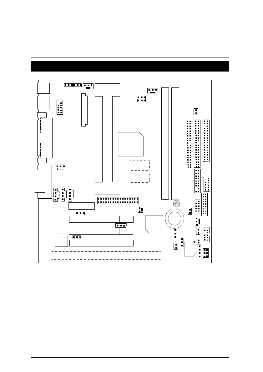
VGA
COMA
FWH32
J7
JP9
J8
CPU
Display
Display
6WMM Series Motherboard Layout
PS/2
USB
JP21
JP13
J15
6WMM
JP33
GMCH
82810
JP12
JP17
JP10
Cache
Cache
JP11
IDE2
IDE1
JP22
ISA
YMF
744
AMR
PCI SLOT1
PCI SLOT2
JP32
PCI SLOT3
J21
TV/DFP
J4
J2
ICH
82801
BAT1
JP6
JP5
BZ1
JP18
J9
J6
J1
J17
J5
JP30
JP7
JP2
JP31
JP1
5
Page 13

6WMM Series Motherboard Layout
$
Page Index for CPU Speed Setup / Connectors / Panel and Jumper
Page
Definition
CPU Speed Setup P.8
Connectors P.9
Game & Audio Port P.9
COMA / VGA / LPT Port P.9
COMB Port / USB Connector P.10
TV/DFP P.11
PS/2 Keyboard & PS/2 Mouse Connector P.11
CPU Cooling FAN Power Connector P.12
PWR Cooling FAN Power Connector P.12
SYSTEM Cooling FAN Power Connector P.13
ATX Power P.13
IR/CIR P.14
Floppy Port P.14
IDE 1(Primary)/ IDE 2(Secondary) Port P.15
J2 (Ring Power On) P.15
J4 (Wake on LAN) P.16
J7 (CD Audio Line In) P.16
JP9 (TEL) P.17
J8 (AUX IN) P.17
JP31 (USB Port Selection) P.18
JP30 (Front Panel USB Port) P.18
J17 (Front Panel Jumper)(Optional) P.19
J22 (Front Audio Jumper) (Optional) P.19
JP33 (SPDIF) P.20
Panel and Jumper Definition P.21
J9 (2x11 pins jumper) P.21
JP13 (Keyboard Power On) P.22
J21 (USB KB / Mouse Power On Selection) P.22
JP6 (Clear CMOS Function) P.23
JP7 (Case Open) P.23
JP2 (STR LED Connector) P.24
JP1 (Top Block Lock) P.24
JP5 (Timeout Reboot Function) P.25
J1 (Buzzer Enable) P.25
6
Page 14

6WMM Series Motherboard
JP32 (Onboard Sound Function Selection) P.26
7
Page 15

6WMM Series Motherboard Layout
JP21 (AMR Selection) P.26
JP11 (STR Enable) P.27
JP18 (Safe mode/Recovery/Normal) P.27
BAT1 P.28
8
Page 16

Page 17

CPU Speed Setup
JP17
JP10
JP17
JP10
1
JP17
JP10
JP17
JP10
1
1
100MHz
JP17
JP10
1
1
(Only GMCH82810E Support)
CPU Speed Setup
The system bus frequency can be switched between 66MHz and 133MHz by adjusting JP17 &
JP10. The CPU Frequency is control by BIOS.
M
The CPU speed must match with the frequency RATIO. It will cause system hanging up
if the frequency RATIO is higher than that of CPU.
Auto detect CPU Speed
1
1
JP10 JP17
Auto 1-2close 1-2close
66M 2-3close 2-3close
100M Open 2-3close
133M Open Open
66MHz
1
«Note: Please set the CPU host frequency in accordance with your processor’s
specifications. We don’t recommend you to set the system bus frequency over
the CPU’s specification because these specific bus frequencies are not the
standard specifications for CPU, chipset and most of the peripherals. Whether
your system can run under these specific bus frequencies properly will depend
on your hardware configurations, including CPU, Chipsets, SDRAM,
Cards….etc.
«Note: JP17 is only available when the mother board use 82810E chipset.
1
1
133MHz
8
Page 18

6WMM Series Motherboard
GAME
Connectors
Game & Audio Port
Port
COM A / VGA / LPT Port
Line Out
LPT PORT
COM A
MIC
Line In
VGA
9
Page 19

COM B Port
2 10
5
USB Connector
COM B
6
1 2 3
9
1
Pin No. Definition
8
7
1 USB V0
2 USB D03 USB D0+
4 GND
5 USB V1
6 USB D17 USB D1+
4
8 GND
Connectors
10
Page 20

6WMM Series Motherboard
TV/DFP : TV-Out / Digital Flat Panel Daughter card connector.
RED LINE
PS/2 Keyboard & PS/2 Mouse Connector
PS/2 Mouse
6
4
2
5
3
1
PS/2 Keyboard
PS/2 Mouse/
Keyboard
Pin No. Definition
1 Data
2 NC
3 GND
4 VCC(+5V)
5 Clock
6 NC
11
Page 21

CPU Cooling FAN Power Connector
1
Pin No. Definition
Power Cooling FAN Power Connector
Connectors
1
1 GND
2 +12V
3 SENSE
Pin No. Definition
1 GND
2 +12V
3 SENSE
12
Page 22

6WMM Series Motherboard
System Cooling FAN Power Connector
Pin No. Definition
ATX Power
11
1
10
20
1
1 GND
2 +12V
3 SENSE
Pin No. Definition
3,5,7,13,
15-17
1,2,11 3.3V
4,6,19,20 VCC
10 +12V
12 -12V
18 -5V
8 Power Good
9 5V SB stand by+5V
14 PS-ON(Soft On/Off)
GND
13
Page 23

J6 : IR/CIR
Floppy Port
10
6
Pin No. Definition
1 VCC
5
2 NC
3 IRRX
1
4 GND
5 IRTX
6 NC
7 CIRRX
8 VCC
9 NC
10 NC
RED LINE
Connectors
14
Page 24

6WMM Series Motherboard
IDE 1
IDE1(Primary) , IDE2 (Secondary) Port
RED LINE
IDE 2
J2 : Ring Power On (Internal Modem Card Wake Up)
1
Pin No. Definition
1 Signal
2 GND
15
Page 25

J4 : Wake on LAN
1
J7 : CD Audio Line In
Connectors
1
Pin No. Definition
1 +5V SB
2 GND
3 Signal
Pin No. Definition
1 CD-L
2 GND
3 GND
4 CD-R
16
Page 26

6WMM Series Motherboard
1
1
JP9 : TEL: The connector is for Modem with internal voice connector
Pin No. Definition
1 Signal -In
2 GND
3 GND
4 Signal-Out
J8 : AUXIN
Pin No. Definition
1 AUX-L
2 GND
3 GND
4 AUX-R
17
Page 27

JP31 : USB Port Selection
9 2
Connectors
6
2
Front Panel USB Enable Back Panel USB Enable
FPUSB(Default) BPUSB
1-3close 3-5close
2-4close 4-6close
JP30 : Front Panel USB Port
Pin No. Definition
1,4,5,10 NC
2 +5V
3,7,9 GND
6 USBP0+
8 USBP0-
5
1
10
1
18
Page 28

6WMM Series Motherboard
J17 : Front Panel Jumper (Optional)
1
15
J22 : Front Audio Jumper (Optional)
1
9
Pin No. Definition
2
1 HD LED+
2 GN LED+
3 HD LED-
4 PWR LED+
5,7 RESET SW
6,8 Soft ON/OFF
10,12 Green SW
16
9 +5V
11 IR RX
13 GND
15 IRTX
14 NC
16 IR Power
Pin No. Definition
2
1 LINE-OUT–L
3 LINE-OUT–R
5 AUX-L
7 AUX-R
10
9 MIC -IN
10 MIC
8 NC
2,4,6 GND
19
Page 29

Connectors
JP33 : SPDIF(The SPDIF output is capable of providing digital audio to
external speakers or compressed AC3 data to an external Dobly Digital
decoder.)
1
Pin No. Definition
1 VCC
2 SPD OUT
3 GND
20
Page 30

6WMM Series Motherboard
RE
GD
PW
P+
HD
1
1
Panel and Jumper Definition
Panel Jumper
1
−
P
−
P
1
1
GN (Green Switch) Open: Normal Operation
Close: Entering Green Mode
GD (Green LED) Pin 1: LED anode(+)
Pin 2: LED cathode(−)
HD (IDE Hard Disk Active LED) Pin 1: LED anode(+)
Pin 2: LED cathode(−)
SPKR (Speaker Connector) Pin 1: VCC(+)
Pin 2- Pin 3: NC
Pin 4: Data(−)
RE (Reset Switch) Open: Normal Operation
Close: Reset Hardware System
P+P−P−(Power LED)
Pin 1: LED anode(+)
Pin 2: LED cathode(−)
Pin 3: LED cathode(−)
PW (Soft Power Connector) Open: Normal Operation
Close: Power On/Off
21
Page 31

JP13 : Keyboard Power On
Pin No. Definition
1-2 close Keyboard Power on
2-3 close Keyboard Power on
JP21 : USB KB/Mouse Wake up Selection
Panel and Jumper Definition
1
Enabled
Disabled (Default)
1
Pin No. Definition
1-2 close
Enable USB KB / Mouse
Wake up
2-3 close Disable USB KB /Mouse
Wake up(Default)
22
Page 32

6WMM Series Motherboard
1
JP6 : Clear CMOS Function
JP7 : Case Open
1
Pin No. Definition
1-2 close Clear CMOS
2-3 close Normal (Default)
Pin No. Definition
1 Signal
2 GND
23
Page 33

JP2 : STR LED Connector
+
JP1 : Top Block Lock
Panel and Jumper Definition
STR LED Connector External.
RAM Indicator LED1
1
1
Pin No. Definition
Open TBL Lock
Close UN Lock
24
Page 34

6WMM Series Motherboard
1
JP5 : Timeout Reboot Function
1
Pin No. Definition
Open Timeout
reboot
Close No Reboot
on timeout
J1 : Buzzer Enable
Pin No.
Definition
Open Internal Buzzer
Disable
Close Internal Buzzer
Enable (Default)
25
Page 35

JP32 : Onboard Sound Function Selection
Pin No. Definition
1-2 close
2-3 close
J21 : AMR Selection
Panel and Jumper Definition
1
Disable
Onboard sound
Enable
Onboard sound
(Default)
1
Pin No. Definition
1-2close Secondary AMR
2-3close Disable CODEC
26
Page 36

6WMM Series Motherboard
JP11 : STR Enable
Pin No. Definition
Open STR Disabled
Close STR Enabled
JP18 : Normal / Safe mode / Recovery
1
(Default)
1
Pin No. Definition
1-2close Normal(Default)
2-3close Safe mode
1-2-3open
Recovery
27
Page 37

BAT1 : Battery
+
Danger of explosion if battery
Panel and Jumper Definition
+
is incorrectly replaced.
+ Replace only with the same or
equivalent type recommended
by the manufacturer.
Dispose of used batteries
+
according to the manufacturer’s
instructions.
28
Page 38

6WMM Series Motherboard
Performance List
The following performance data list is the testing results of some popular
benchmark testing programs.
These data are just referred by users, and there is no responsibility for different
testing data values gotten by users. (The different Hardware & Software
configuration will result in different benchmark testing results.)
• CPU
• DRAM (128x1)MB SDRAM (Winbond 902WB 986408BH-8H)
• CACHE SIZE 512 KB included in CPU
• DISPLAY Onboard Intel Corporation 810 Graphics and Memory
• STORAGE Onboard IDE (IBM DJNA-371800)
• O.S. Windows NT™ 4.0 SPK5
• DRIVER Display Driver at 1024 x 768 x 16bit colors x 75Hz.
Pentium III 500MHz processor
Controller Hub (4MB SDRAM)
Processor
Intel Pentium III
500MHz(100x5)
Winbench99
CPU mark99
FPU Winmark 99
Business Disk Winmark 99
Hi-End Disk Winmark 99
Business Graphics Winmark 99
Hi-End Graphics Winmark 99
38.2
2560
3650
6370
149
344
Winstone99
Business Winstone99
Hi-End Winstone99
29
30
24.7
Page 39

Block Diagram
82801AA
SDRAM
SDRAM
W83627
Block Diagram
Display
Display Cache
ATA66 IDE Channels
2 USB Ports
COM Ports
LPT Ports
INTEL Slot 1
Winbond
IR Floppy
PS/2
Processor
Host Bus 66/100/133MHz
GMCH
82810E
Hub
Interface
ICH
FWH
Game Port
66/100/133 MHz
66/100/133 MHz
3.3V SDRAM
14.318/33/48/66 MHz
PCI Bus 33MHz
AC’97 Link
YMF
744
AC’97
100 MHz
ICS
9248-96
4 PCI
3 COM
30
Page 40

6WMM Series Motherboard
Suspend to RAM Installation
A.1 Introduce STR function:
Suspend-to-RAM (STR) is a Windows 98 ACPI sleep mode function. When
recovering from STR (S3) sleep mode, the system is able, in just a few
seconds, to retrieve the last “state” of the system before it went to sleep and
recover to that state. The “state” is stored in memory (RAM) before the
system goes to sleep. During STR sleep mode, your system uses only
enough energy to maintain critical information and system functions,
primarily the system state and the ability to recognize various “wake up”
triggers or signals, respectively.
A.2 STR function Installation
Please use the following steps to complete the STR function installation.
Step-By-Step Setup
Step 1:
To utilize the STR function, the system must be in Windows 98 ACPI mode.
Putting Windows 98 into ACPI mode is fairly easy.
Setup with Windows 98 CD:
A. Insert the Windows 98 CD into your CD-ROM drive, select Start, and then Run.
B. Type (without quotes) “D:\setup /p j” in the window provided. Hit the enter key or click
OK.
C. After setup completes, remove the CD, and reboot your system
(This manual assumes that your CD-ROM device drive letter is D:).
31
Page 41

Suspend to RAM installation
Step 2:
(If you want to use STR Function, please set jumper JP11 (Closed.)
1
Pin No. Definition
Open STR Disabled
(Default)
Close STR Enabled
Step 3:
Power on the computer and as soon as memory counting starts, press <Del>. You will enter
BIOS Setup. Select the item “POWER MANAGEMENT SETUP”, then select “ACPI Suspend
Type: S3 (Suspend to RAM)”. Remember to save the settings by pressing "ESC" and choose
the “SAVE & EXIT SETUP” option.
Congratulation! You have completed the installation and now can use the STR function.
32
Page 42

6WMM Series Motherboard
A.3 How to put your system into STR mode?
There are two ways to accomplish this:
1. Choose the “Stand by” item in the “Shut Down Windows” area.
A. Press the “Start” button and then select “Shut Down”
B. Choose the “Stand by” item and press “OK”
33
Page 43

Suspend to RAM installation
2. Define the system ”power on” button to initiate STR sleep mode:
A. Double click “My Computer” and then “Control Panel”
B. Double click the “ Power Management” item.
34
Page 44

6WMM Series Motherboard
C. Select the “Advanced” tab and “Standby” mode in Power Buttons.
Step 4:
Restart your computer to complete setup.
Now when you want to enter STR sleep mode, just momentarily press the “Power on” button..
A.4 How to recover from the STR sleep mode?
There are six ways to “wake up” the system:
1. Press the “Power On” button.
2. Use the “Keyboard Power On” function.
3. Use the “Mouse Power On” function.
4. Use the “Resume by Alarm” function.
5. Use the “Modem Ring On” function.
6. Use the “Wake On LAN” function.
35
Page 45

Suspend to RAM installation
+
A.5 Notices :
1. In order for STR to function properly, several hardware and software requirements must be
satisfied:
A. Your ATX power supply must comply with the ATX 2.01 specification (provide more than
720 mA 5V Stand-By current).
B. Your SDRAM must be PC-100 compliant.
2. Jumper JP2 is provided to connect to the STR LED in your system chassis. [Your chassis
may not provide this feature.] The STR LED will be illuminated when your system is in STR
sleep mode.
STR LED Connector External.
RAM Indicator LED1
1
36
Page 46

6WMM Series Motherboard
Memory Installation
The motherboard has 2 dual inline memory module (DIMM) sockets. The BIOS will automatically
detects memory type and size. To install the memory module, just push it vertically into the DIMM
Slot .The DIMM module can only fit in one direction due to the two notch. Memory size can vary
between sockets.
Install memory in any combination table:
DIMM 168-pin SDRAM DIMM Modules
DIMM 1 Supports 16 / 32 / 64 / 128 / 256 / 512 MB X 1 pcs
DIMM 2 Supports 16 / 32 / 64 / 128 / 256 / 512 MB X 1 pcs
37
 Loading...