

Page 1

686LX4
USER'S MANUAL
1. System power on by PS/2 Mouse: First, enable this function
in CMOS Setup, then you can power on the system by
double clicking the right or left button of your PS/2 Mouse.
2. System power on by Keyboard: If your ATX power supply
supports larger than 100~300 mA 5V Stand-By current
(dependent on the specification of keyboard), you can
power on your system by entering password from the
Keyboard after setting the “Keyboard power on” jumper
(JP1) and password in CMOS Setup.
3. Support 3 steps ACPI LED selectable.
4. Support Modem Ring-On on COM A , COM B.
5. Support Wake-up on LAN. (Your ATX power supply must
support larger than 720 mA 5V Stand-By current)
M J16(ATX PWR Ctrl)/J19(Ring Pow On)/JP8(Clear CMOS)
Power FAN/System FAN Jumpers for PCB Rev: 2.0/2.2 use,
please reference P15¡BP16¡BP17
M PCI 2.1 For PCB Rev 2.0
M PCI 2.2 For PCB Rev 2.2
For Intel Pentium II / CeleronTM Processor MAINBOARD
R-22-01-081103
Page 2

REV. 2.2 First Edition
2
Page 3

686LX4
The author assumes no responsibility for any errors or omissions that may
appear in this document nor does it make a commitment to update the
information contained herein.
Sound Blaster is a registered trademark of Creative Technology Ltd in the
United States and certain other countries. Sound Blaster-LINK and SB-LINK
are trademarks of Creative Technology Ltd.
Third-party brands and names are the property of their respective owners.
Dec 03, 1998 Taipei, Taiwan
1
Page 4
Quick Installation Guide
I. Quick Installation Guide :
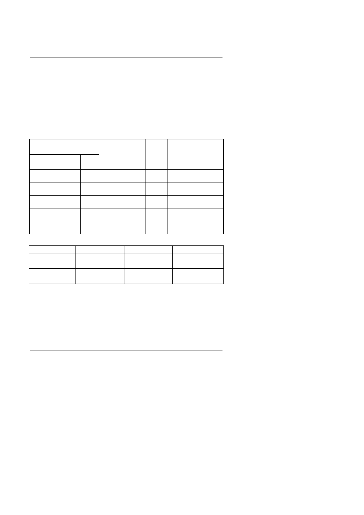
CPU SPEED SETUP
The default system bus speed is 66.6MHz. The user can change the DIP
SWITCH (SW) selection to set up the CPU speed for 233 - 633MHz
processor.
The CPU speed MUST match with the frequency RATIO. It will cause
system hanging up if the frequency RATIO is higher than that of CPU.
DIP SWITCH (SW)
1 2 3 4
OFF OFF ON ON 3.5 66 233
ON ON OFF ON 4 66 266
OFF ON OFF ON 4.5 66 300
ON OFF OFF ON 5 66 333
OFF OFF OFF ON 5.5 66 366
REQ.
RATIO
. MHz
. MHz
CPU Type
Pentium II 233 MHz
(Celeron 233MHz)
Pentium II 266 MHz
(Celeron 266MHz)
Pentium II 300 MHz
(Celeron 300MHz)
Pentium II 333 MHz
(Celeron 333MHz)
Pentium II 366 MHz
(Celeron 366MHz)
MJP2, JP3, JP4 (Select the system speed¡Ð66 / 75 / 83 / 100MHz )
Main Clock JP4 JP3 JP2
66 MHz 1-2 1-2 1-2
75 MHz 1-2 2-3 1-2
83 MHz 2-3 1-2 2-3
100 MHz 1-2 2-3 2-3
«
Note: We don’ t recommend you to setup your system speed to 75,
83 or 100MHz because these frequencies are not the standard
specifications for CPU, Chipset and most of the peripherals.
Whether your system can run under 75, 83 or 100MHz properly
will depend on your hardware configurations: CPU, SDRAM,
Cards, etc.
2
Page 5
686LX4
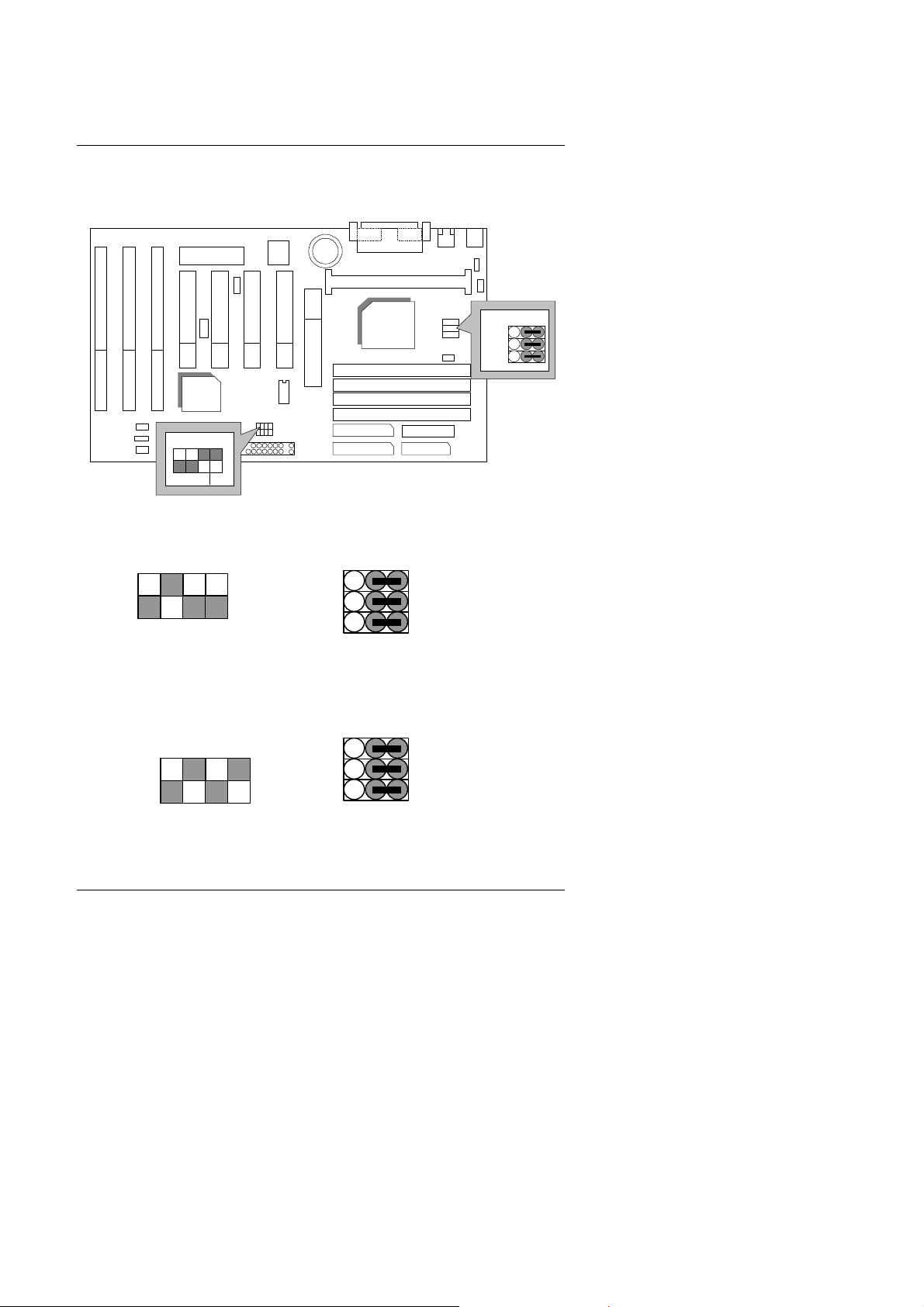
686LX4
1. Pentium II / Celeron 233 MHz / 66MHz FSB
BIOS
INTEL
443LX
PIIX4
1234
ON
JP2
JP3
JP4
2. Pentium II / Celeron 266MHz / 66MHz FSB
4 3
SW
JP2
JP3
ON
JP4
3 2
3. Pentium II / Celeron 300MHz / Celeron 300A MHz / 66MHz
FSB
4 3
JP2
JP3
SW
ON
JP4
3 2
123
3
Page 6
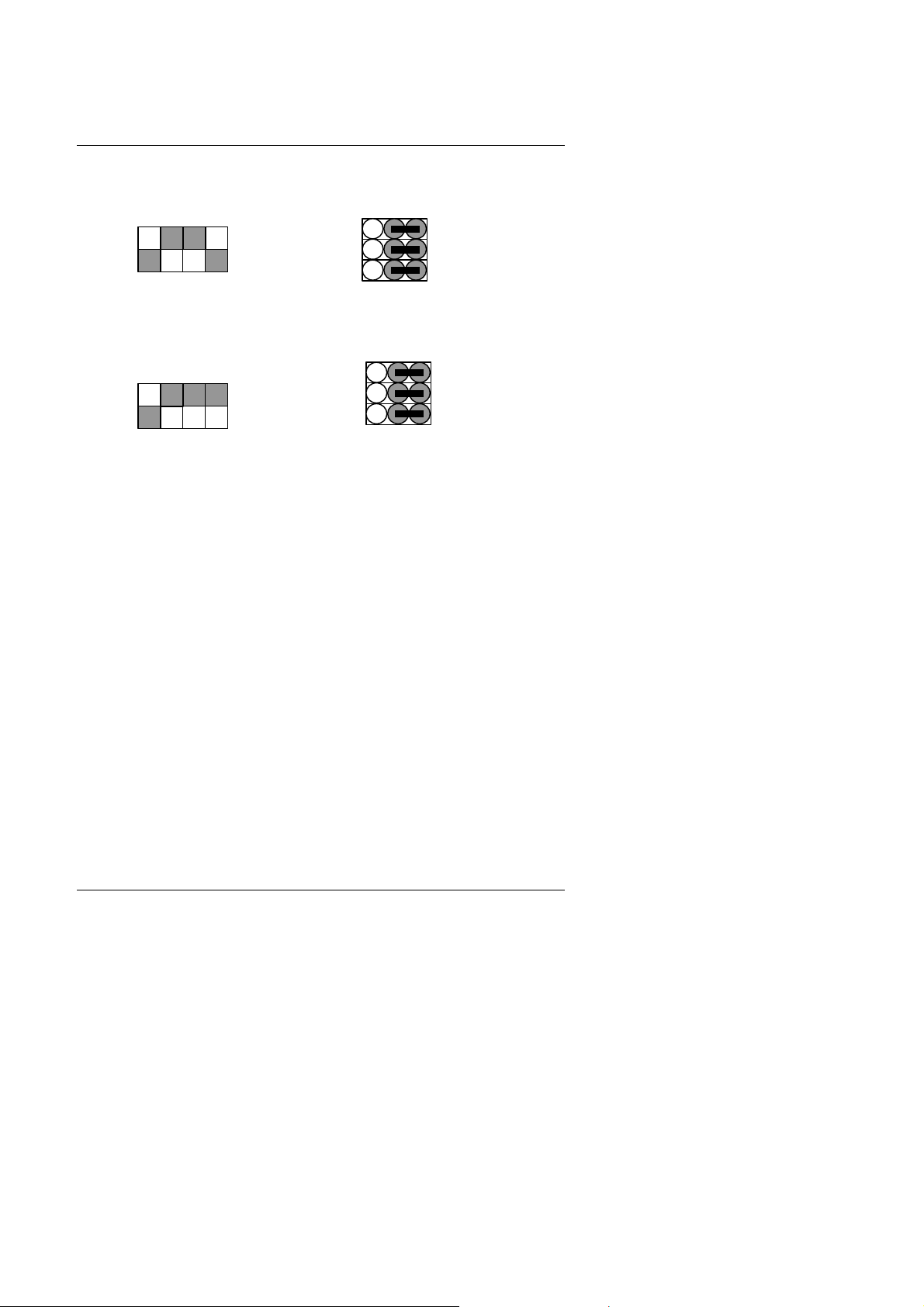
4. Pentium II / Celeron 333MHz / 66MHz FSB
Quick Installation Guide
4 3
JP2
JP3
SW
ON
JP4
3 2
5. Pentium II / Celeron 366 MHz / 66MHz FSB
4 3
JP2
JP3
SW
ON
JP4
3 2
4
Page 7
686LX4
II. Jumper setting :
GN : Green Function Switch
BIOS
PIIX4
GD : Green Function LED
INTEL
443LX
Open:
Normal
operation
Short:
Green mode
1
PIIX4
BIOS
INTEL
443LX
PIN FUNCTION
1
1
LED (+)
2
LED (-)
5
Page 8

HD : IDE Hard Disk Active LED
BIOS
PIIX4
INTEL
443LX
Quick Installation Guide
SPKR : Speaker Connector
BIOS
PIIX4
1
INTEL
443LX
1
PIN FUNCTION
1
LED (+)
2
LED (-)
PIN FUNCTION
1 VCC
2 NC
3 NC
4 Data
6
Page 9

686LX4
RES : Reset Switch
BIOS
PIIX4
PWR : Power LED Connector
BIOS
INTEL
443LX
Open:
Normal
operation
Short:
Reset system
PIIX4
INTEL
443LX
1
PIN FUNCTION
1 LED (+)
2
LED (−)
3
LED (−)
7
Page 10

PWR SW : Soft Power Connector
BIOS
PIIX4
INTEL
443LX
Quick Installation Guide
1
IR : Infrared Connector (Optional)
BIOS
PIIX4
1
PIN FUNCTION
1
CTRL-Signal
2 GND
INTEL
443LX
PIN NO. Function
1
IR Data Output
2
3
4
5
GND
IR Data Input
Signal
POWER (+)
8
Page 11

686LX4
GND
VCC
ATX PWR : ATX Power Connector
BIOS
PIIX4
PS/2 Mouse / Keyboard Connector
BIOS
INTEL
443LX
Pin No.
3,5,7,13,15-17
4,6,19,20
10
12
18
8
9
14
11
1
Function
+12V
-12V
-5V
Power Good
5V SB
(Stand by +5V)
PS-ON
(Soft ON/OFF)
PS/2 Mouse
PIIX4
INTEL
443LX
PS/2 Keyboard
PS/2 Mouse/Keyboard
Pin No.
Function
1
Data
2
NC
3
GND
4
VCC (+5V)
5 Clock
6 NC
9
Page 12

CPU FAN : CPU Cooling Fan Power Connector
BIOS
INTEL
443LX
PIIX4
IDE1: For Primary IDE port
BIOS
Quick Installation Guide
1
PIN FUNCTION
1 GND
2 +12V
3 SENSE
PIIX4
10
INTEL
443LX
RED LINE
1
Page 13

686LX4
IDE2: For Secondary IDE port
BIOS
PIIX4
FLOPPY: FLOPPY PORT
BIOS
INTEL
443LX
RED LINE
1
PIIX4
11
INTEL
443LX
RED LINE
1
Page 14

LPT PORT / COM A / COM B
Quick Installation Guide
BIOS
PIIX4
JP1: Keyboard Power On
BIOS
PIIX4
INTEL
443LX
INTEL
443LX
LPT PORT
COM B
COM A
Keyboard Power On
Default: Disable
1-2
2-3
1
2
3
Enable
Disable
12
Page 15

686LX4
BIOS
CN1: USB Port
PIIX4
J13:Wake On LAN
1
BIOS
Pin No. Function
1 +5V SB
2 GND
3 Signal
INTEL
443LX
Pin No.
1
2
3
4
5
6
7
8
Function
USB V0
USB D0USB D0+
GND
USB V1
USB D1USB D1+
GND
PIIX4
13
INTEL
443LX
Page 16

SB-LINK : For PCI Audio / Sound Card use only
–
(Creative PCI Sound Card Support)
Quick Installation Guide
BIOS
PIIX4
BAT1 : For Battery
BIOS
PIIX4
1 2
5 6
Pin No.
4
Function
1 Signal
2 GND
3 NC
4 Signal
5 GND
6 Signal
INTEL
443LX
INTEL
443LX
+
M Danger of explosion if battery is incorrectly replaced.
M Replace only with the same or equivalent type recommended by the
manufacturer.
M Dispose of used batteries according to the manufacturer’ s instructions.
14
Page 17

686LX4
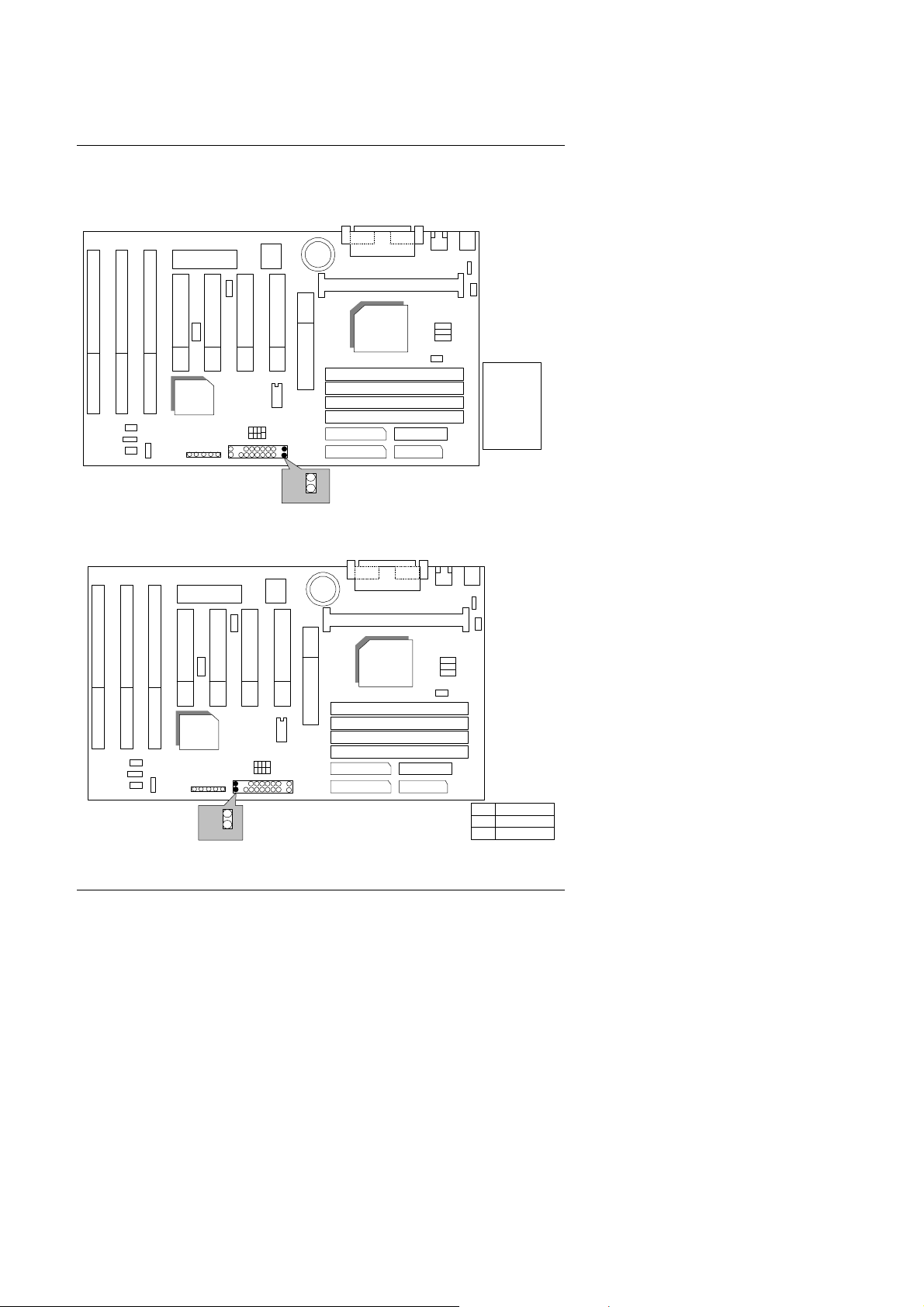
J16: ATX Power Control Selection (Only for PCB Rev:2.0 use)
BIOS
INTEL
443LX
PIIX4
J16
Open: Soft Off
Close: Full On
POWER FAN: Power Fan power connector (Only for PCB Rev:2.2
use)
BIOS
INTEL
443LX
PIIX4
15
1
PIN FUNCTION
1 GND
2 +12V
3 SENSE
Page 18

SYSTEM FAN: System Fan power connector
(Only for PCB Rev:2.2 use)
BIOS
INTEL
443LX
PIIX4
1
JP8: CLEAR CMOS (Only for PCB Rev:2.2 use)
Quick Installation Guide
PIN FUNCTION
1 GND
2 +12V
3 SENSE
BIOS
PIIX4
1-2 Short :Clear CMOS
1
2-3 Short :Normal
Default: 2-3 Short
16
INTEL
443LX
Page 19

686LX4
J19: Ring PWR ON(Only for PCB Rev:2.2 use)
BIOS
INTEL
443LX
PIIX4
1
J19
Pin No. Function
12+5V SB
GND
17
Page 20

Quick Installation Guide
III. Top Performance Test Setting:
The following performance data list is the testing results of some popular
benchmark testing programs.
Users have to modify the value for each item in chipset features as follow
for top performance setting.
18
Page 21

686LX4
These data are just referred by users, and there is no responsibility for
different testing data values gotten by users. (The different Hardware &
Software configuration will result in different benchmark testing results.)
• CPU
• DRAM (32 x 2) MB SDRAM (LGS GM72V16821GT10K)
• CACHE SIZE 512 KB included in CPU
• DISPLAY 600 AGP Display Card (4MB SGRAM)
• STORAGE Onboard IDE (IBM DHEA-34330)
• O.S. Windows® 95 OSR2.1
• DRIVER Display Driver at 1024 x 768 x 64k colors x 75Hz.
Processor
Pentium II processor
Triones Bus Master IDE Driver 3.70
Intel Pentium II
266MHz 300MHz
Winbench97
CPU mark32 692 759
Business Disk 1940 2070
Hi-End Disk 5900 6210
Business Graphics 116 126
Hi-End Graphics 50.8 55.4
Winstone97
Business 62.1 64.8
Hi-End 30.7 32.1
19
Page 22

 Loading...