


Hardware Installation
To complete the mainboard installation, the peripheral device could be
installed now. The basic system needs a display interface card.
If the PCI - Bus device is to be installed in the system, any one of five PCI Bus slots can be used.
3.12. KEYBOARD & PS/2 MOUSE INSTALLATION
The main board supports PS/2 connector type keyboard & Mouse (CN5).
The BIOS will auto detect whether the PS/2 Mouse is installed or nor &
assign IRQ12 for Mouse port if which was installed.
After installing the peripheral device, the user should check everything again,
and prepare to power-on the system.
3.13. KEYBOARD SETTING FUNCTION
After booting the O.S., there are some special functions used by keyboard as
follows:
"CTRL_ALT_DEL" − Pressing these keys simultaneously will cause
system to Warm Start (Software Reset).
3-7


GA-686LX
4. BIOS CONFIGURATION
Award's BIOS ROM has a built-in Setup program that allows users to modify
the basic system configuration.
This type of information is stored in battery-backed CMOS SRAM so that it
retains the Setup information when the power is turned off.
4.1. ENTERING SETUP
Power ON the computer and press <Del> immediately will allow you to enter
Setup.
The other way to enter Setup is to power on the computer, when the below
message appears briefly at the bottom of the screen during the POST
(Power On Self Test), press <Del> key or simultaneously
press <Ctrl>, <Alt>, and <Esc> keys.
Ÿ
TO ENTER SETUP BEFORE BOOT PRESS CTRL-ALT-ESC OR DEL KEY
If the message disappears before you respond and you still wish to enter
Setup, restart the system to try again by turning it OFF then ON or pressing
the "RESET" bottom on the system case.
You may also restart by simultaneously press <Ctrl>, <Alt>, and <Del> keys.
If you do not press the keys at the correct time and the system does not boot,
an error message will be displayed and you will again be asked to,
Ÿ
PRESS F1 TO CONTINUE, CTRL-ALT-ESC OR DEL TO ENTER SETUP
4-1

BIOS Configuration
4.2. CONTROL KEYS
Up arrow Move to previous item
Down arrow Move to next item
Left arrow Move to the item in the left hand
Right arrow Move to the item in the right hand
Esc key Main Menu - Quit and not save changes into CMOS
Status Page Setup Menu and Option Page Setup Menu -
Exit current page and return to Main Menu
PgUp key Increase the numeric value or make changes
PgDn key Decrease the numeric value or make changes
F1 key General help, only for Status Page Setup Menu and
Option Page Setup Menu
F2 key Change color from total 16 colors
F3 key Calendar, only for Status Page Setup Menu
F4 key Reserved
F5 key Restore the previous CMOS value from CMOS, only for
Option Page Setup Menu
F6 key Load the default CMOS value from BIOS default table,
only for Option Page Setup Menu
F7 key Load the default
F8 key Reserved
F9 key Reserved
F10 key Save all the CMOS changes, only for Main Menu
4-2
GA-686LX
4.3. GETTING HELP
4.3.1. Main Menu
The on-line description of the highlighted setup function is displayed at the
bottom of the screen.
4.3.2. Status Page Setup Menu / Option Page Setup Menu
Press F1 to pop up a small help window that describes the appropriate keys
to use and the possible selections for the highlighted item. To exit the Help
Window press <Esc>.
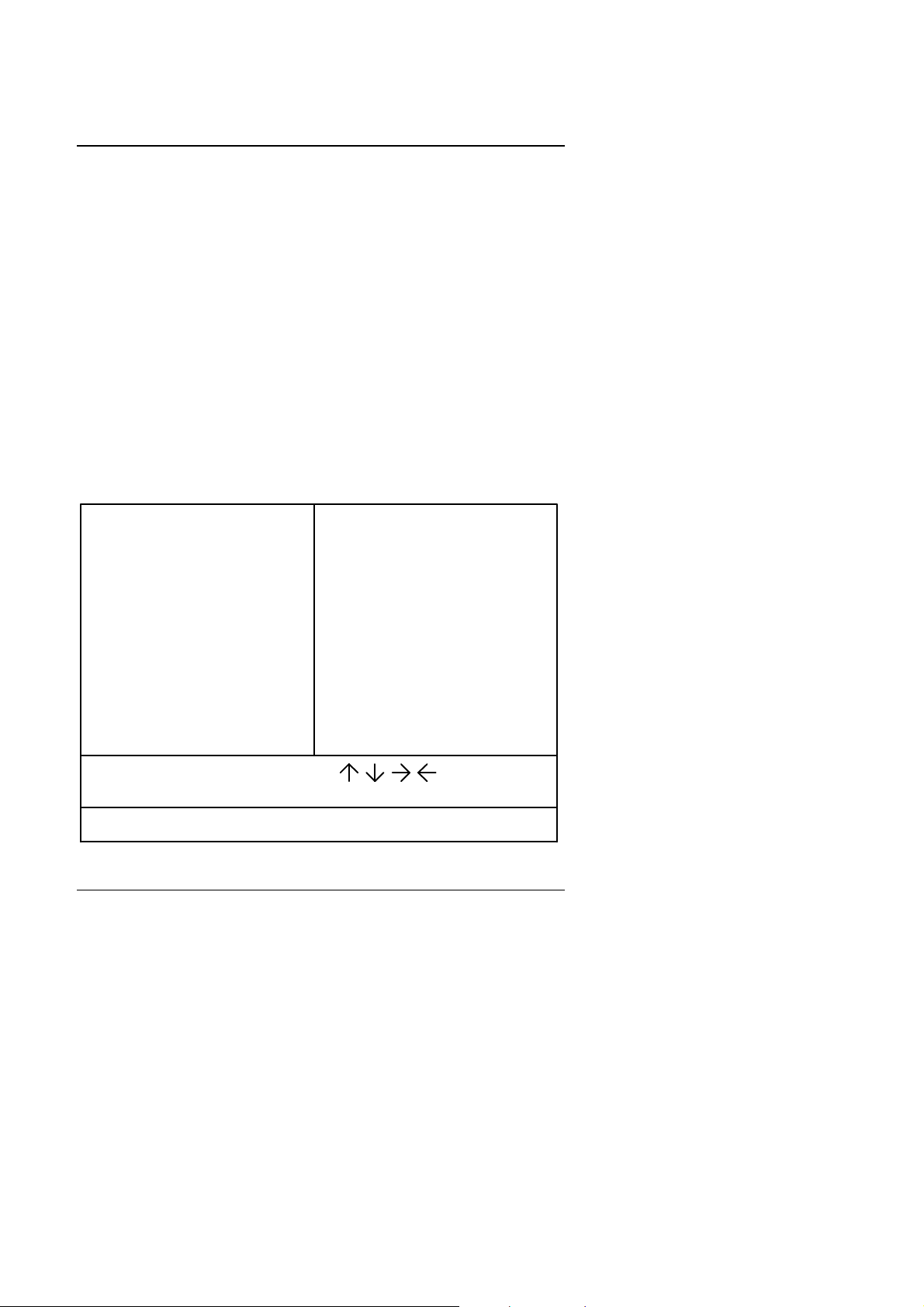
4.4. THE MAIN MENU
Once you enter Award BIOS CMOS Setup Utility, the Main Menu (Figure 4.1)
will appear on the screen.
The Main Menu allows you to select from seven setup functions and two exit
choices. Use arrow keys to select among the items and press <Enter> to
accept or enter the sub-menu.
ROM PCI / ISA BIOS
CMOS SETUP UTILITY
AWARD SOFTWARE, INC.
STANDARD CMOS SETUP
BIOS FEATURES SETUP
CHIPSET FEATURES SETUP
POWER MANAGEMENT SETUP
PNP/PCI CONFIGURATION
INTEGRATED PERIPHERALS
LOAD SETUP DEFAULTS
ESC
: Quit
F10
: Save & Exit Setup (Shift)F2
Time, Date, Hard Disk Type, ...
Figure 4.1: Main Menu
USER PASSWORD
IDE HDD AUTO DETECTION
SAVE & EXIT SETUP
EXIT WITHOUT SAVING
: Select Item
: Change Color
4-3

BIOS Configuration
• Standard CMOS setup
This setup page includes all the items in a standard compatible BIOS.
• BIOS features setup
This setup page includes all the items of Award special enhanced
features.
• Chipset features setup
This setup page includes all the items of chipset special features.
• Power management setup
This setup page includes all the items of Green function features.
• PNP/PCI configuration
This setup page includes all the configurations of PCI & PNP ISA
resources.
• Integrated peripherals
This setup page includes all onboard peripherals.
• Load setup defaults
BIOS defaults indicates the most appropriate value of the system
parameter which the system would be in safe configuration.
• User password
Change, set, or disable password. It allows you to limit access to the
system and Setup, or just to Setup.
• IDE HDD auto detection
Automatically configure hard disk parameter.
• Save & exit setup
Save CMOS value changes to CMOS and exit setup.
• Exit without save
Abandon all CMOS value changes and exit setup.
4-4
GA-686LX
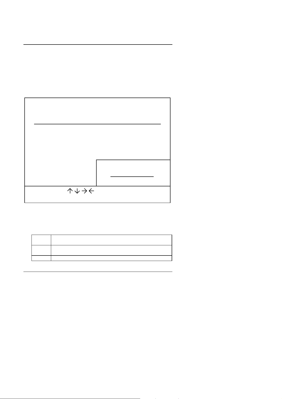
4.5. STANDARD CMOS SETUP MENU
The items in Standard CMOS Setup Menu (Figure 4.2) are divided into 9
categories. Each category includes no, one or more than one setup items.
Use the arrows to highlight the item and then use the <PgUp> or <PgDn>
keys to select the value you want in each item.
ROM PCI / ISA BIOS
STANDARD CMOS SETUP
AWARD SOFTWARE, INC.
Date (mm:dd:yy)
Time (hh:mm:ss)
Primary
Primary
Secondary Master
Secondary
Driver A
Driver B
Floppy 3 Mode Support : Disabled
Video
Halt On : All Errors
ESCF1: Quit
: Help (Shift)F2
: Mon, Aug 25 1997
: 16 : 45 : 02
Master
Slave
Slave
: 1.44M , 3.5 in.
: None
: EGA/VGA
: Auto
: None
: None
: None
HEAD PRECOMP LANDZ SECTOR
CYLSHARD DISKS TYPE MODE
SIZE
0
0
0
0
Extended Memory:
: Select Item
: Change Color
000 0
Base Memory:
Other Memory:
Total Memory:
PU/PD/+/- : Modify
0
0000 0
0000 0
0000 0
640 K
15360 K
384 K
16384 K
Figure 4.2: Standard CMOS Setup Menu
• Date
The date format is <day>, <date> <month> <year>. Press <F3> to show
the calendar.
day The day, from Sun to Sat, determined by the BIOS and is
display-only
date The date, from 1 to 31 (or the maximum allowed in the
month)
month The month, Jan. through Dec.
Auto
---------
---------
---------
4-5
BIOS Configuration
year The year, from 1994 through 2079
• Time
The times format in <hour> <minute> <second>. The time is calculated
base on the 24-hour military-time clock. For example, 1 p.m. is
13:00:00.
• Primary HDDs / Secondary HDDs
The category identifies the types of hard disk drive C drives F 4 devices
that has been installed in the computer. There are 45 pre-defined types
and a user definable type. Type 1 to Type 45 are pre-defined. Type User
is user-definable and type Auto will automatically detect HDD's type.
Press PgUp or PgDn to select a numbered hard disk type or type the
number and press <Enter>. Note that the specifications of your drive
must match with the drive table. The hard disk will not work properly if
you enter improper information for this category.
If your hard disk drive type is not matched or listed, you can use Type
User to define your own drive type manually. If you select Type User,
related information is asked to be entered to the following items. Enter
the information directly from the keyboard and press <Enter>. Those
information should be provided in the documentation form your hard
disk vendor or the system manufacturer.
CYLS. Number of cylinders
HEADS number of heads
PRECOMP write precomp
LANDZONE landing zone
SECTORS number of sectors
If a hard disk has not been installed select NONE and press <Enter>.
• Drive A type / Drive B type
The category identifies the types of floppy disk drive A or drive B that
has been installed in the computer.
None No floppy drive installed
360K, 5.25 in. 5.25 inch PC-type standard drive; 360K byte
capacity.
1.2M, 5.25 in. 5.25 inch AT-type high-density drive; 1.2M byte
capacity (3.5 inch when 3 Mode is Enabled).
4-6

GA-686LX
720K, 3.5 in. 3.5 inch double-sided drive; 720K byte capacity
1.44M, 3.5 in. 3.5 inch double-sided drive; 1.44M byte capacity.
2.88M, 3.5 in. 3.5 inch double-sided drive; 2.88M byte capacity.
• Floppy 3 Mode Support (for Japan Area)
Disable Normal Floppy Drive.
Drive A Drive A is 3 mode Floppy Drive.
Drive B Drive B is 3 mode Floppy Drive.
Both Drive A & B is 3 mode Floppy Drive.
• Video
The category detects the type of adapter used for the primary system
monitor that must matches your video display card and monitor.
Although secondary monitors are supported, you do not have to select
the type in setup.
EGA/VGA Enhanced Graphics Adapter/Video Graphics Array. For
EGA, VGA, SVGA, or PGA monitor adapters
CGA 40 Color Graphics Adapter, power up in 40 column mode
CGA 80 Color Graphics Adapter, power up in 80 column mode
MONO Monochrome adapter, includes high resolution
monochrome adapters
• Halt on
The category determines whether the computer will stop if an error is
detected during power up.
NO errors The system boot will not be stopped for any error
that may be detected
All errors Whenever the BIOS detects a non-fatal error the
system will be stopped and you will be prompted
All, But Keyboard The system boot will not stop for a keyboard
error; it will stop for all other errors
All, But Diskette The system boot will not stop for a disk error; it
will stop for all other errors
4-7

BIOS Configuration
All, But Disk/Key The system boot will not stop for a keyboard or
disk error; it will stop for all other errors
• Memory
The category is display-only which is determined by POST (Power On
Self Test) of the BIOS.
Base Memory
The POST of the BIOS will determine the amount of base (or
conventional) memory installed in the system.
The value of the base memory is typically 512 K for systems
with 512 K memory installed on the motherboard, or 640 K for
systems with 640 K or more memory installed on the
motherboard.
Extended Memory
The BIOS determines how much extended memory is present
during the POST.
This is the amount of memory located above 1 MB in the CPU's
memory address map.
Expanded Memory
Expanded Memory in memory defined by the
Lotus/Intel/Microsoft (LIM) standard as EMS.
Many standard DOS applications can not utilize memory above
640 K; the Expanded Memory Specification (EMS) swaps
memory, which not utilized by DOS with a section, or frame, so
these applications, can access all of the system memory.
Memory can be swapped by EMS is usually 64 K within 1 MB or
memory above 1 MB, depends on the chipset design.
Expanded memory device driver is required to use memory as
Expanded Memory.
Other Memory
This refers to the memory located in the 640 K to 1024 K
address space. This is memory that can be used for different
applications.
DOS uses this area to load device drivers to keep as much
4-8
GA-686LX
base memory free for application programs. Most use for this
area is Shadow RAM.
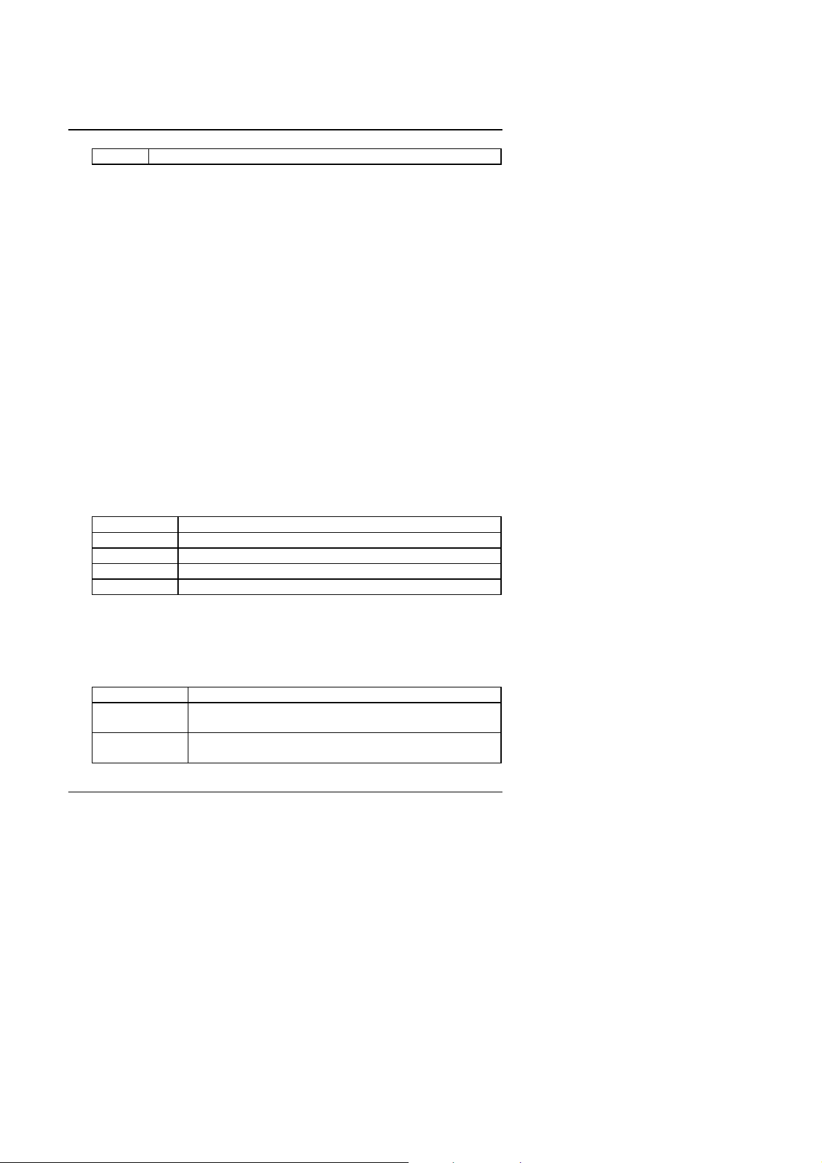
4.6. BIOS FEATURES SETUP
ROM PCI / ISA BIOS
BIOS FEATURES SETUP
AWARD SOFTWARE, INC.
Virus Warning
CPU Internal Cache
External Cache
Quick Power On Self Test
Boot Sequence
Swap Floppy Drive : Disabled
Boot Up Floppy Seek
Boot Up NumLock Status
Typematic Rate Setting
Typematic Rate (Chars/Sec)
Typematic Delay (Msec)
Security Option
PCI/VGA Palette Snoop : Disabled
OS Select For DRAM >64MB : Non-OS2
: Disabled
: Enabled
: Enabled
: Enabled
: A, C, SCSI
: Enabled
: On
: Disabled
: 6
: 250
: Setup
Video BIOS Shadow
C8000 - CBFFF Shadow
CC000 - CFFFF Shadow : Disabled
ESC
: Quit
F1
: Help
F5
: Old Values
F7 : Load Setup Defaults
PU/PD/+/(Shift)F2
: Enabled
: Disabled
: DisabledD0000 - D3FFF Shadow
: DisabledD4000 - D7FFF Shadow
: DisabledD8000 - DBFFF Shadow
: DisabledDC000 - DFFFF Shadow
: Select Item
: Modify
: Color
Figure 4.3: BIOS Features Setup
• Virus Warning
This category flashes on the screen. During and after the system boots
up, any attempt to write to the boot sector or partition table of the hard
disk drive will halt the system and the following error message will
appear, in the mean time, you can run anti-virus program to locate the
problem. Default value is Disabled.
Enabled Activate automatically when the system boots up causing
a warning message to appear when anything attempts to
access the boot sector or hard disk partition table
Disabled No warning message to appear when anything attempts to
access the boot sector or hard disk partition table
• CPU Internal Cache / External Cache
These two categories speed up memory access. However, it depends on
CPU / chipset design. The default value is Enabled.
Enabled Enable cache
4-9

BIOS Configuration
Disabled Disable cache
• Quick Power On Self Test
This category speeds up Power On Self Test (POST) after you power on
the computer. If it is set to Enable, BIOS will shorten or skip some check
items during POST.
The default value is Disabled.
Enabled Enable quick POST
Disabled Normal POST
• Boot Sequence
This category determines which drive computer searches first for the
disk operating system (i.e., DOS). Default value is A, C, SCSI.
X1, X2, X3 System will first search for X1 disk drive then X2 disk
drive and then X3 disk drive.
• Swap Floppy Drive
The default value is Disabled.
Enabled Floppy A & B will be swapped under DOS
Disabled Floppy A & B will be normal definition
• Boot Up Floppy Seek
During POST, BIOS will determine if the floppy disk drive installed is 40
or 80 tracks. 360 K type is 40 tracks while 720 K, 1.2 M and 1.44 M are
all 80 tracks.
The default value is Enabled.
Enabled BIOS searches for floppy disk drive to determine if it is 40
or 80 tracks. Note that BIOS can not tell from 720 K, 1.2 M
or 1.44 M drive type as they are all 80 tracks
Disabled BIOS will not search for the type of floppy disk drive by
track number. Note that there will not be any warning
message if the drive installed is 360 K
• Boot Up NumLock Status
The default value is On.
On Keypad is number keys
4-10

GA-686LX
Off Keypad is arrow keys
• Typematic Rate Setting
The default value is Disabled.
Enabled Enable Keyboard Typematic rate setting.
Disabled Disable Keyboard Typematic rate setting.
• Typematic Rate (Chars / Sec)
The default value is 6.
6-30 Set the maximum Typematic rate from 6 chars. Per
second to 30 chars. Per second.
• Typematic Delay (Msec)
The default value is 250.
250-1000 Set the time delay from first key to repeat the same key
in to computer.
• Security Option
This category allows you to limit access to the system and Setup, or just
to Setup.
The default value is Setup.
System The system will not boot and access to Setup will be
denied if the correct password is not entered at the prompt
Setup The system will boot, but access to Setup will be denied if
the correct password is not entered at the prompt
M
To disable security, select PASSWORD SETTING at Main Menu and
then you will be asked to enter password. Do not type anything and
just press <Enter>, it will disable security. Once the security is
disabled, the system will boot and you can enter Setup freely.
• PCI/VGA Palette Snoop
The default value are Disabled.
Enabled For having Video Card on ISA Bus and VGA Card on PCI
Bus.
Disabled For VGA Card only.
4-11

BIOS Configuration
• OS Select For DRAM>64MB
The default value is Non-OS2.
Non-OS2 Using non-OS2 operating system.
OS2 Using OS2 operating system and DRAM>64MB.
• Video BIOS Shadow
It determines whether video BIOS will copied to RAM, however, it is
optional from chipset design. Video Shadow will increase the video
speed.
The default value is Enable.
Enabled Video shadow is enabled
Disabled Video shadow is disabled
• C8000 - CFFFF Shadow / D0000 - DFFFF Shadow
These categories determine whether optional ROM will be copied to
RAM by 16 K byte.
The default value are Disabled.
Enabled Optional shadow is enabled
Disabled Optional shadow is disabled
4-12
GA-686LX
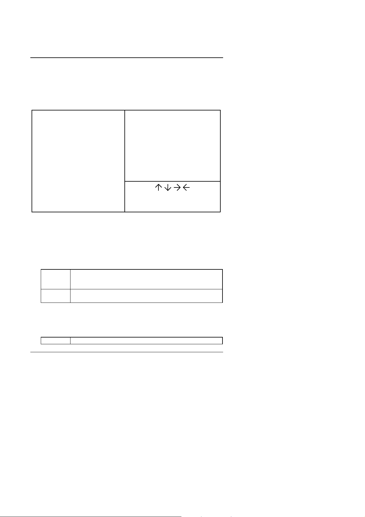
4.7. CHIPSET FEATURES SETUP
ROM PCI / ISA BIOS
CHIPSET FEATURES SETUP
AWARD SOFTWARE, INC.
Auto Configuration
DRAM Speed Selection : Slow
DRAM Data Integrity Mode
Video RAM Cacheable : Disabled
Memory Hole At 15M-16M : Disabled
Delayed Transaction : Disabled
SDRAM RAS-to-CAS Delay
SDRAM RAS Precharge Time
SDRAM CAS latency Time
: Enabled
: Non-ECC
: Slow
: Slow
: 3
Figure 4.4: Chipset Features Setup
• Auto Configuration
The default value is Enabled.
Enable For 50 - 60ns EDO DRAM Timing.
Disable For slow speed DRAM Timing.
• DRAM speed selection
The default value is Slow.
CPU Temperature Select
CPU Temperature : High
Fan Failure Control : Disabled
CPU Fan Status : Fail
Power Supply +12V
Power Supply -12V
Power Supply +5V
Power Supply -5V
Battery Status
CPU VCore Voltage
: Quit
F1
: Help
F5
: Old Values
F7 : Load Setup Defaults
PU/PD/+/(Shift)F2
: 75¢J/167
: OK
: Fail
: OK
: Fail
: OK
: 2.8V
: Select ItemESC
: Modify
: Color
¢K
Slow For normal DRAM operation.
Fast For Fastest DRAM timing operation.
• DRAM Data Integrity Mode
The default value is Non-ECC.
Non-ECC For 64bit standard type DIMM module.
ECC For 72bit ECC type DIMM module.
4-13

BIOS Configuration
• Video RAM Cacheable
The default value is Disabled.
Disabled Disable this function.
Enabled Enable this function to better VGA performance; while
some brands of VGA must be disabled this function
(e.g.ET4000W32P).
• Memory Hole At 15M-16M
The default value is Disabled.
Disabled Normal Setting.
Enabled Set Address=15~16MB remap to ISA BUS.
• Delayed Transaction
The default value is Disabled.
Disabled Normal operation.
Enabled For slow speed ISA device in system.
• SDRAM RAS-to-CAS Delay
The default value is Slow.
Slow For 67 / 83 MHz SDRAM DIMM module.
Fast For 100 MHz SDRAM DIMM module.
• SDRAM RAS Precharge Time
The default value is Slow.
Slow For 67 / 83 MHz SDRAM DIMM module.
Fast For 100 MHz SDRAM DIMM module.
• SDRAM CAS latency Time
The default value is 3.
3 For 67 / 83 MHz SDRAM DIMM module.
2 For 100 MHz SDRAM DIMM module.
4-14

GA-686LX
• CPU Temperature Select
The default value is 75°C / 167°F.
75°C / 167°F Monitor CPU Temp. at 75°C, if Temp. > 75°C will
cause system alarming & slow down CPU speed.
70°C / 158°F Monitor CPU Temp. at 70°C, if Temp. > 70°C will
cause system alarming & slow down CPU speed.
Disabled Disable monitors CPU Temp. (Overheat) function.
• CPU Temperature
The default value depend on CPU TEMP. status.
High CPU overheats. (CPU Temperature is out of SPEC.)
OK CPU Temp. is in SPEC.
• Fan Failure Control
The default value is Disabled.
Disabled Disable monitor CPU FAN working status.
Enabled Enable monitor CPU FAN working if CPU FAN fail to
work, will cause system alarming & slow down CPU
speed.
• CPU Fan Status
The default value depends on system monitoring CPU FAN status.
Fail The CPU FAN fails to work.
OK The CPU FAN works normally.
• Power Supply +12V
The default value depends on system monitoring +12V voltage status.
Fail The +12 voltage from POWER supply is out of SPEC.
OK The +12 voltage from POWER supply is in SPEC.
• Power Supply -12V
The default value depends on system monitoring -12V voltage status.
Fail The -12 voltage from POWER supply is out of SPEC.
OK The -12 voltage from POWER supply is in SPEC.
4-15
 Loading...