

Page 1

GA-4KXSV
Pentium Prescott 1066 Motherboard
USER’S MANUAL
Pentium®Prescott Processor Motherboard
Rev. 1001
12ME-4KXSVRH-1001R
Page 2

GA-4KXSV-RH Motherboard
Table of Content
English
Item Checklist .........................................................................................4
WARNING!...............................................................................................4
Chapter 1 Introduction............................................................................5
Chapter 2 Hardware Installation Process...............................................9
Chapter 3 BIOS Setup ..........................................................................33
Chapter 4 INTEL RAID BIOS Configuration ...........................................53
Features Summary...................................................................................... 5
GA-4KXSV Motherboard Layout.................................................................. 7
2-1: Installing Processor and CPU Haet Sink .............................................9
2-1-1: Installing CPU ......................................................................................................... 9
2-1-2: Installing Heat Sink ............................................................................................... 10
2- 2: Install memory modules ....................................................................11
2-3: Install expansion cards ...................................................................... 13
2- 4: Connect ribbon cables, cabinet wires, and power supply................14
2-4-1 : I/O Back Panel Introduction................................................................................ 14
2-4-2 : L AN LED De sc rip ti on .......................................................................................... 16
2- 5: Connectors Introduction....................................................................17
2- 6: Jumper Setting .................................................................................. 28
2- 7: Block Diagram...................................................................................32
The Main Menu ............................................................................................................... 34
2-1 Standard CMOS Features........................................................................................ 36
2-2 Advanced BIOS Features ........................................................................................ 38
2-3 Integrated Peripherals ............................................................................................... 40
2-4 Power Management Setup ...................................................................................... 43
2-5 PnP/PCI Configurations............................................................................................ 45
2-6 PC Health Status ....................................................................................................... 46
2-7 Frequency/Voltage Control ...................................................................................... 48
2-8 Load Fail-Safe Defaults............................................................................................. 50
2-9 Load Optimized Defaults........................................................................................... 50
2-10 Set Supervisor/User Password ............................................................................ 51
2-11Save & Exit Setup .................................................................................................... 52
2-12Exit Without Saving.................................................................................................. 52
2
Page 3

Introduction
Item Checklist
The GA-4KXSV motherboard Serial ATA cable x 4
IDE (ATA100 ) cable x 1 / Floppy cable x 1 I/O Shield Kit
CD for motherboard driver & utility
GA-4KXSV user’s manual
WARNING!
Computer motherboards and expansion cards contain very delicate Integrated Circuit (IC) chips. To
protect them against damage from static electricity, you should follow some precautions whenever you
work on your computer.
1. Unplug your computer when working on the inside.
2. Use a grounded wrist strap before handling computer components. If you do not have
one, touch both of your hands to a safely grounded object or to a metal object, such as
the power supply case.
3. Hold components by the edges and try not touch the IC chips, leads or connectors, or
other components.
4. Place components on a grounded antistatic pad or on the bag that came with the
components whenever the components are separated from the system.
5. Ensure that the ATX power supply is switched off before you plug in or remove the ATX
power connector on the motherboard.
Installing the motherboard to the chassis…
If the motherboard has mounting holes, but they don’t line up with the holes on the base and
there are no slots to attach the spacers, do not become alarmed you can still attach the spacers to
the mounting holes. Just cut the bottom portion of the spacers (the spacer may be a little hard to
cut off, so be careful of your hands). In this way you can still attach the motherboard to the base
without worrying about short circuits. Sometimes you may need to use the plastic springs to isolate
the screw from the motherboard PCB surface, because the circuit wire may be near by the hole. Be
careful, don’t let the screw contact any printed circuit write or parts on the PCB that are near the
fixing hole, otherwise it may damage the board or cause board malfunctioning.
3
Page 4

GA-4KXSV-RH Motherboard
Chapter 1 Introduction
Features Summary
English
Form Factor y 12” x 9.6” ATX size form factor, 6 layers PCB.
CPU y Supports Intel® Pentium® 4 / Pentium® D processor
Chipset y Intel® 945G Chipset
Memory y 4 x DDRII socket up to 4 GB
I/O Control y ITE IT8712F-A Super I/O
Expansion Slots y Supports 2 PCI slots 32-Bit/33MHz (5V)
SATA RAID Controller y ICH7R built in SAT A RAID 0,1,5, 0+1 without Linux support
IDE RAID Controller y ITE IT8212F built in IDE RAID 0,1, 0+1
On-Board Peripherals y 1 IDE connector
Hardware Monitor y CPU/Power/System Fan Revolution Detect
®
y Intel
y L2 cache on-die per processor from 1M
y Intel
y Intel
y Supports Dual Channel Un-buffered DDRII 400/533/667
y Support 256MB, 512MB, and 1GB memory
y Supports 2 PCI-X slots 64-Bit/133MHz
y Supports 1 PCI-Express x1 slot
y Supports 1 PCI-Express x16 slot
y Supports 4 SAT AII conntectors
y 1 Floppy port supports 2 FDD with 360K, 720K,1.2M, 1.44M
y 2 PS/2 connectors
y 1 Parallel port supports Normal/EPP/ECP mode
y 1 Serial port (COM)
y 4 x USB 2.0
y 1 VGA connector
y 1 x LAN RJ45
y 4 x SAT AII connectors
y CPU shutdown when overheat
y System Voltage Detect
Prescott LGA 775 supports 533/800/1066MHz FSB
®
ICH7R
®
6700 PXH
and 2.88M bytes.
4
Page 5

Introduction
On-Board Graphic y Build in Intel® 945G Chipset
On-Board Audio y Realtek® ALC 880
On-Board LAN y Intel 82573V Gigabit Ethernet controllers
Hardware Monitor y ITE IT8712F-A controller
y Enhanced features with CPU Vcore, DDRII 1.8V reference,
VCC3 (3.3V), VCC5V, +12V, +5V SB, CPU Temperature, and
System Temperature Values viewing by
BIOS y AWARD BIOS on 4Mb flash RAM
Additional Features y PS/2 Mouse wake up from S1 under Windows Operating System
y External Modem wake up
y Supports S1, S3, S5 under Windows Operating System
y Wake on LAN (WOL)
y AC Recovery
y Supports Console Redirection
y Supports 4-pin Fan controller
5
Page 6

GA-4KXSV-RH Motherboard
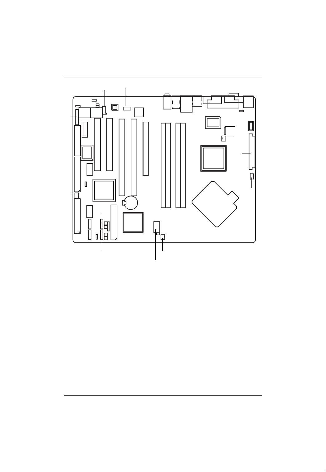
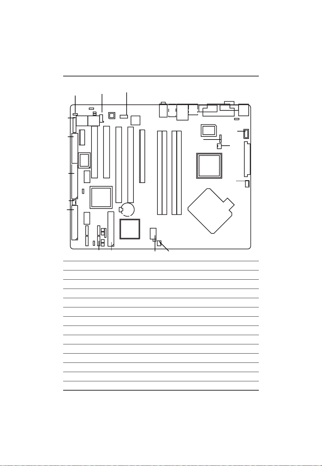
GA-4KXSV Motherboard Layout
English
1. CPU 21. DDRII 3
2. Intel 945G 22. DDRII 4
3. Intel 6700 PXH 23. PCIEX1
4. Intel ICH7R 24. PCI1(Supports 32bit/33MHz)
5. ITE IT8712F 25. PCI2 (Supports 32bit/33MHz)
6. ITE IT8212F GigaRAID 26. PCI-X 1 (Supports 64bit/66~133MHz)
7. Intel 82573V GbE 27. PCI-X 2 (Supports 64bit/66~133MHz)
8. Realtek ALC 880 28. PCIEX16
9. Main BIOS 29. CD_IN
10 Back BIOS 30. F_Audio
11. IDE RAID1 31. IR
12. IDE RAID2 32. F_USB1
13. IDE 33. F_USB2
14. FDD 34. COMB
15 SATA1 35. F_Panel
16. SATA2 36. CPU FAN
17. SATA3 37. NB FAN
18. SATA4 38. System FAN
19. DDRII 1 39. Power FAN
20. DDRII 2 40. ATX
41. ATX12V
6
Page 7
Introduction
35
39
10
23 24 25
14
6
32
11
33
12
15
16
29
30
8
26
27
7
1922 21
20
28
5
31
9
37
40
2
4
36
1
13
18
3
17
38
41
7
Page 8
GA-4KXSV-RH Motherboard
Chapter 2 Hardware Installation Process
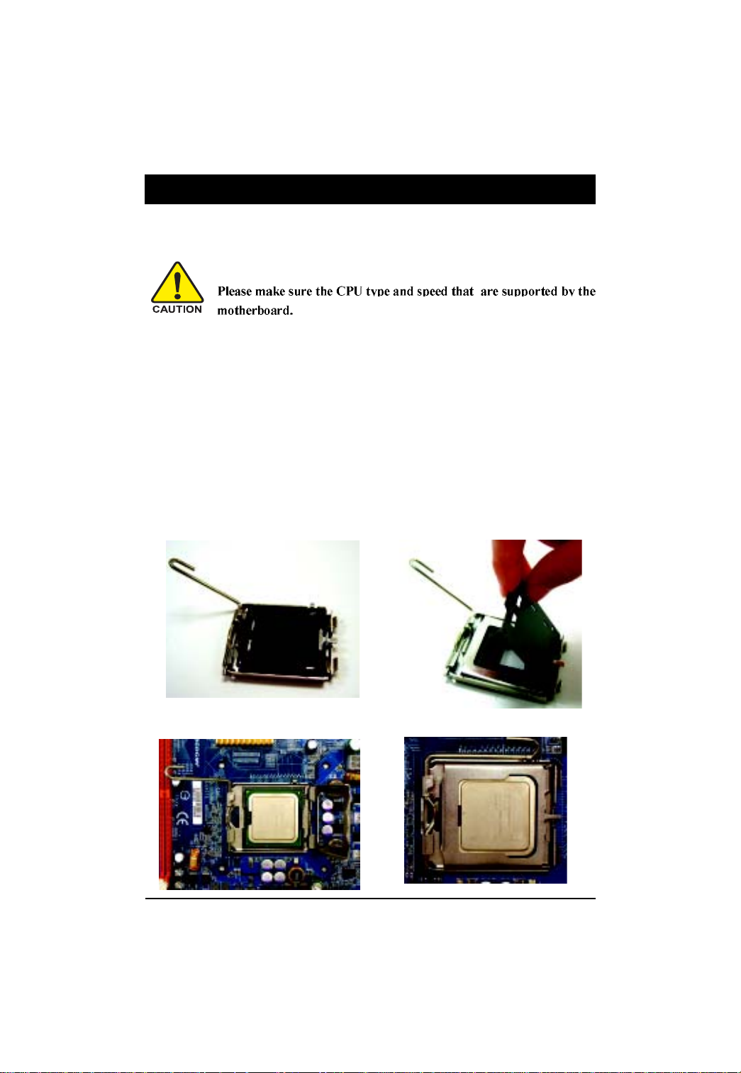
2-1: Installing Processor and CPU Haet Sink
English
2-1-1: Installing CPU
Step 1 Gently lift the metal lever located on the CPU socket to the upper-right position.
Step 2 Remove the plastic covering on the CPU socket.
Step 3 Align the indented corner of the CPU with the triangle and gently insert the CPU into position.
Step 4 Once the CPU is properly inserted, please replace the plastic covering and push the metal
Step 5 Close the lever, reverse step 1 & 2.
(Grasping the CPU firmly between your thumb and forefinger, carefully place it into the socket
in a straight and downwards motion. Avoid twisting or bending motions that might cause
damage to the CPU during installation.)
lever back into its original position.
8
Page 9
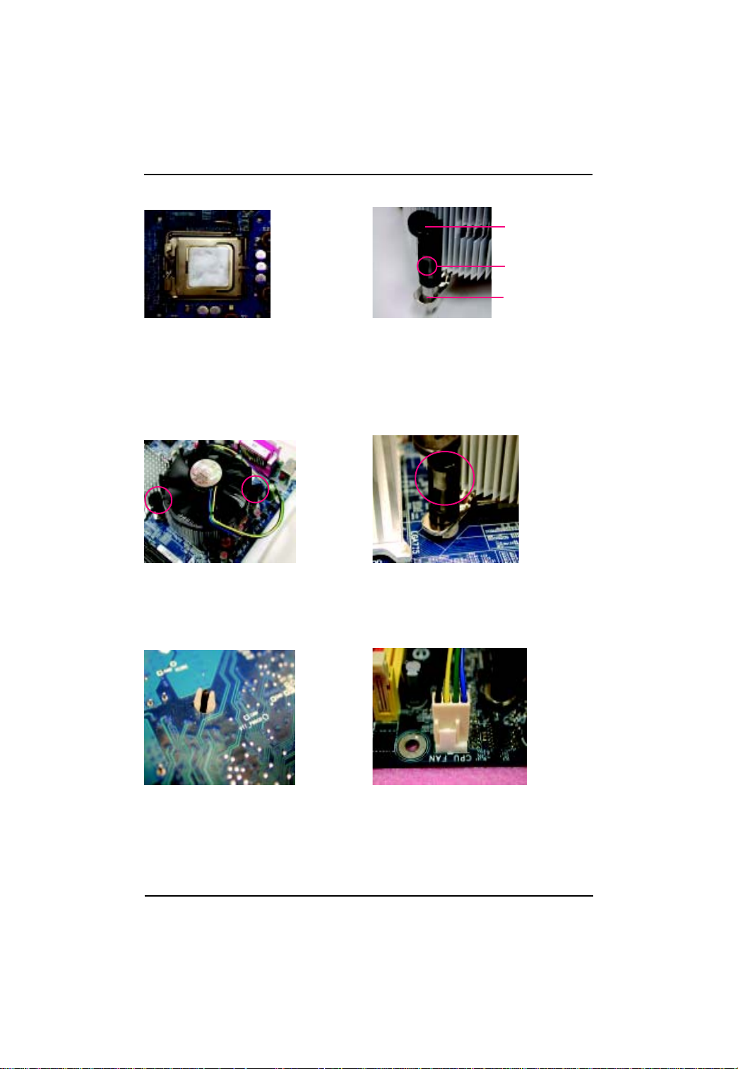
2-1-2: Installing Heat Sink
Hardware Installation Process
Male Push Pin
The top of Female Push Pin
Female Push Pin
Fig.1
Please apply heatsink paste on the surface of
the installed CPU.
Fig. 3
Place the heatsink on top the CPU and make
sure the push pins align to the pin hole on the
motherboard.Push down the push pins
diagonally.
Fig. 2
( to remove the heatsink, turning the push pin along
the direction of arrow; and reverse the previous
step to install the heat sink.)
Please note the direction of arrow sign on the male
push pin doesn't face inwards before installation.
(This instruction is only for Intel boxed fan)
Fig. 4
Please make sure the Male and Female push pin
are brought together. (for detailed installation
instructions, please refer to the heatsink installation
section of the user manual)
Fig. 5
Please check the back side of teh motherboard.
Make sure the push pin is seated firmly as the
picture shown. Installation completed.
Fig. 6
Attach the power connector of the heatsink to the
CPU fan header located on the motherboard.
9
Page 10
GA-4KXSV-RH Motherboard
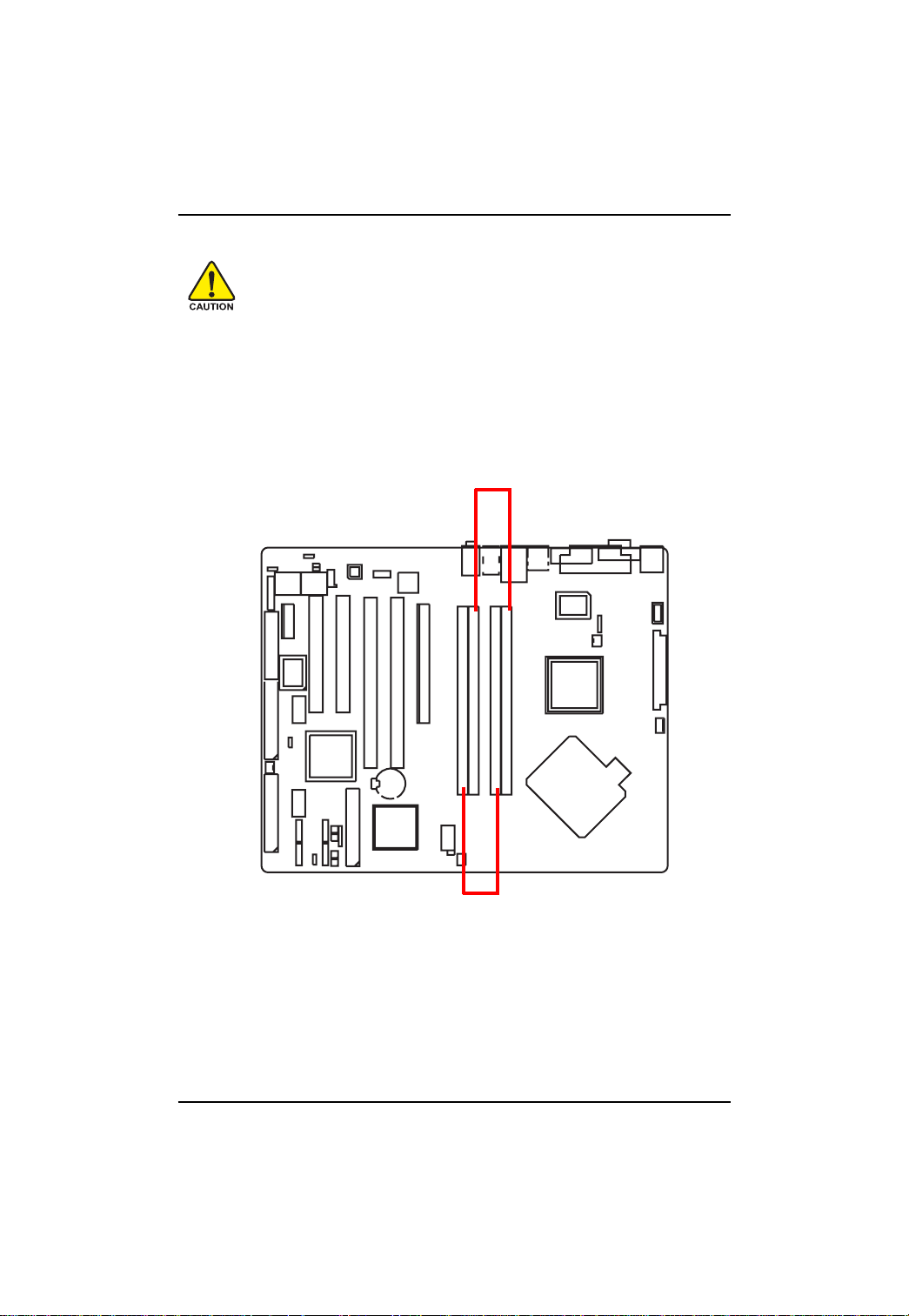
2- 2: Install memory modules
English
When DIMM LED is ON, do not install/remove DIMM from socket.
GA-4KXSV has 4 dual inline memory module (DIMM) socets. It supports the Dual Channel T echnology .
The BIOS will automatically detects memory type and size during system boot. For detail DIMM
installation, please refer to the following instructions.
Before installing the processor and heatsink, adhere to the following warning:
Channel A
Channel B
10
Page 11
Hardware Installation Process
Table 1. Supported DIMM Module Type
Technology Organization SDRAM Chips/DIMM
256MB 8MB x 8 x 4 bks 8
16MB x 4 x 4bks 16
512MB 16MB x 8 x 4bks 8
32MB x 4 x 4bks 16
1GB 32MB x 8 x 4bks 8
64MB x 4 x 4bks 16
Table 2. DIMM Placement DDR2-533/667
DIMM Configuration DIMM1 DIMM2
1 Single Rank Empty Empty
1 Dual Rank Empty Empty
2 Single Rank Empty Single Rank
1 Dual Rank, 1 Single Rank Empty Single Rank
2 Dual Rank Empty Dual Rank
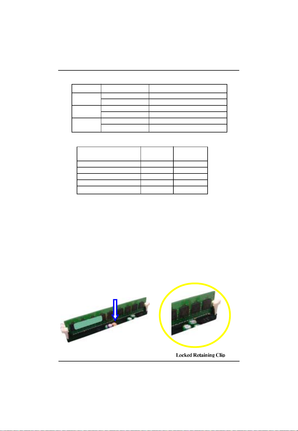
Installation Steps:
1. Unlock a DIMM socket by pressing the retaining clips outwards.
2. Aling a DIMM on the socket such that the notch on the DIMM exactly match the notches in the
socket.
3. Firmly insert the DIMMinto the socket until the retaining clips snap back in place.
4. When installing the DIMM into the DIMM socket, we recommend to populate one DIMM in
Channel A module and one in Channel B module for best performance.
Please note that each logical DIMM must be made of two identical DIMMs having the same
device size on each and the same DIMM size.
5. Reverse the installation steps when you wish to remove the DIMM module.
11
Page 12
GA-4KXSV-RH Motherboard
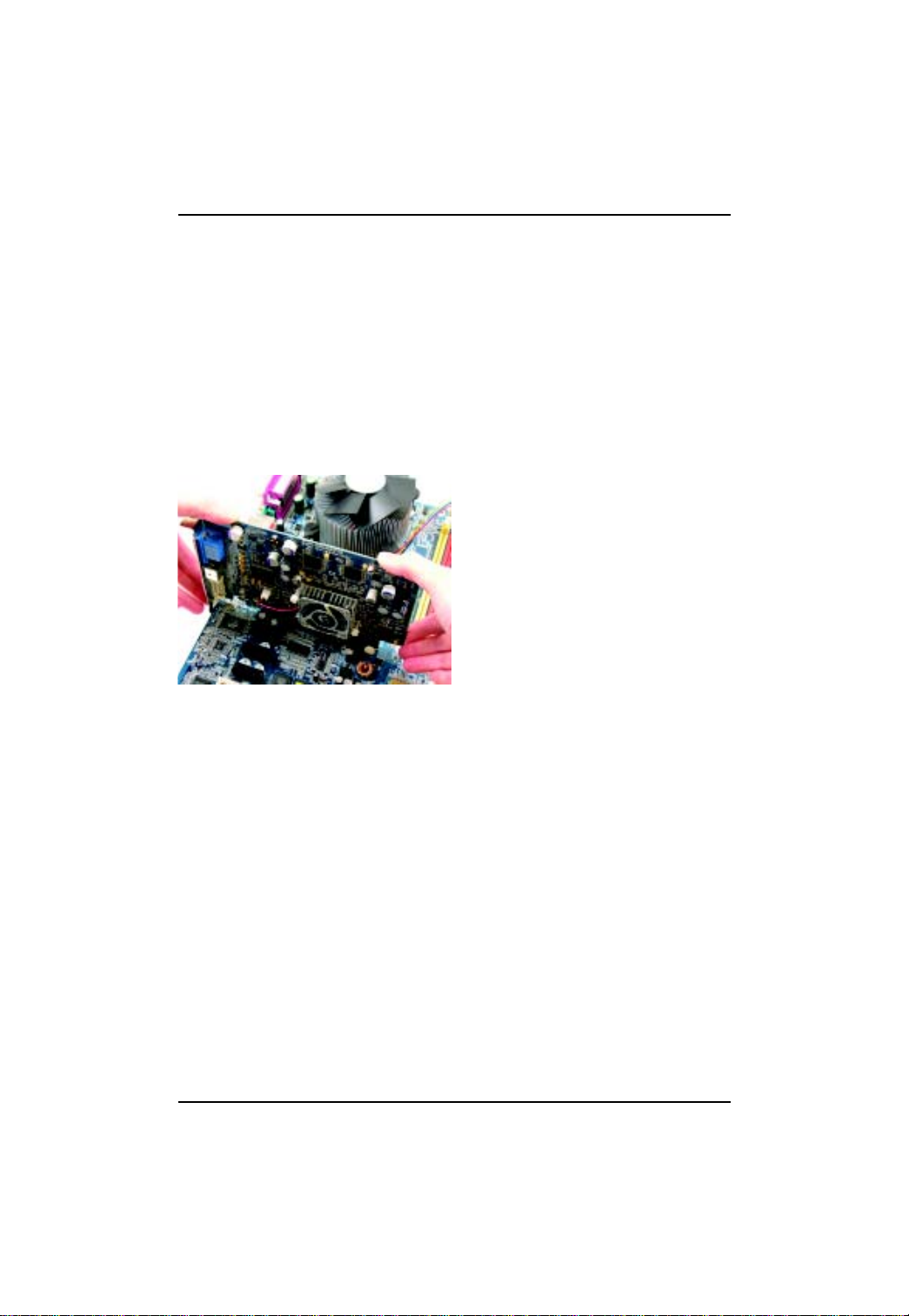
2-3: Install expansion cards
1. Read the related expansion card’s instruction document before install the expansion card into
English
2. Remove your server’s chassis cover, necessary screws and slot bracket from the computer.
3. Press the expansion card firmly into expansion slot in motherboard.
4. Be sure the metal contacts on the card are indeed seated in the slot.
5. Replace the screw to secure the slot bracket of the expansion card.
6. Replace your computer’s chassis cover.
7. Power on the computer, if necessary, setup BIOS utility of expansion card from BIOS.
8. Install related driver from the operating system.
the computer.
12
Page 13
Hardware Installation Process
2- 4: Connect ribbon cables, cabinet wires, and power
supply
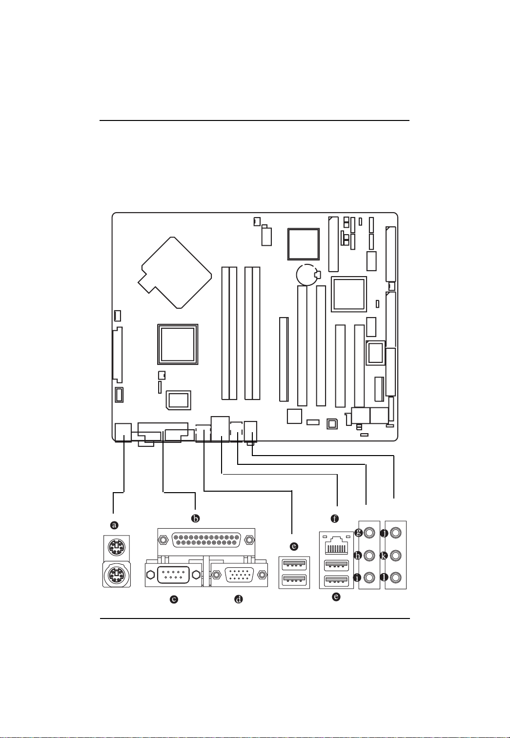
2-4-1 : I/O Back Panel Introduction
13
Page 14

GA-4KXSV-RH Motherboard
English
PS/2 Keyboard and PS/2 Mouse Connector
To install a PS/2 port keyboard and mouse, plug the mouse to the upper port (green) and the keyboard
to the lower port (purple).
Parallel Port
The parallel port allows connection of a printer, scanner and other peripheral devices.
Serial Port
Modem can be connected to Serial port.
VGA Port
Monitor can be connected to VGA port.
LAN Port
The provided Internet connection is Gigabit Ethernet, providing data transfer speeds of
10/100/1000Mbps.
USB Port
Before you connect your device(s) into USB connector(s), please make sure your device(s)
such as USB keyboard, mouse, scanner, zip, speaker...etc. have a standard USB interface.
Also make sure your OS supports USB controller. If your OS does not support USB controller,
please contact OS vendor for possible patch or driver updated. For more information please
contact your OS or device(s) vendors.
Line In
The default Line In jack. Devices like CD-ROM, walkman etc. can be connected to Line In jack.
Line Out (Front Speaker Out)
The default Line Out (Front Speaker Out) jack. Stereo speakers, earphone or front surround
speakers can be connected to Line Out (Front Speaker Out) jack.
MIC In
The default MIC In jack. Microphone must be connected to MIC In jack.
Surround Speaker Out (Rear Speaker Out)
The default Surround Speaker Out (Rear Speaker Out) jack. Rear surround speakers can be
connected to Surround Speaker Out (Rear Speaker Out) jack.
Center/Subwoofer Speaker Out
The default Center/Subwoofer Speaker Out jack. Center/Subwoofer speakers can be connected
to Center/Subwoofer Speaker Out jack.
Side Speaker Out
The default Side Speaker Out jack. Surround side speakers can be connected to Side Speaker
Out jack.
14
Page 15

2-4-2 : LAN LED Description
Hardware Installation Process
Name
LAN
Link/Activity
10/100 LAN
Speed
GbE LAN
Speed
Color Condition Description
Green ON LAN Link / no Access
Green BLINK LAN Access
- OFF Idle
Green ON 100Mbps connection
- OFF 10Mbps connection
Yellow ON 1Gbps connection
Yellow BLINK Port identification with 1Gbps connection
Green ON 100Mbps connection
Green BLINK Port identification with 10 or 100Mbps connection
- OFF 10Mbps connection
15
Page 16
GA-4KXSV-RH Motherboard
2- 5: Connectors Introduction
English
16
18
14
15
6
3
20
4
7
23
8
9
12
10
11
5
1) ATX 15) F_Audio
2) ATX 1 2V 16) Front Panel
3) RAID IDE1 17) IR
4) RAID IDE2 18) PWR_LED
5) IDE 19) CPU FAN
6) FDD 20) PWR FAN
7) F_USB1 21)SYS FAN
8) F_USB2 22)NB F A N
9) SAT A1 23) BAT (Battery)
10) SATA2
11) SATA3
12) SATA4
13) COMB
14)CD_IN
2
21
16
13
17
22
1
19
Page 17
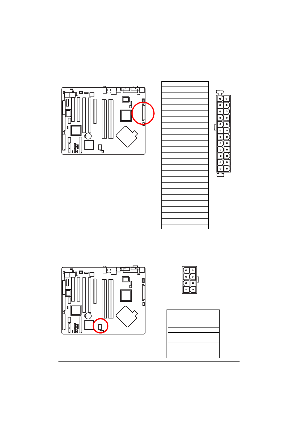
1 ) ATX (ATX Power Connector)
AC power cord should only be connected to
your power supply unit after A TX power cable
and other related devices are firmly connected
to the mainboard.
PIN No. Definition
1 +3.3V
2 +3.3V
3 GND
4 +5V
5 GND
6 +5V
7 GND
8 POK
9 5VSB
10 +12V
11 +12V
12 +3.3V
13 +3.3V
14 -12V
15 GND
16 PSON
17 GND
18 GND
19 GND
20 -5V
21 +5V
22 +5V
23 +5V
24 GND
Connector Introduction
13
1
12
24
2 ) ATX_12V( +12V Power Connector)
This connector (A TX +12V) is used only for
CPU1 Core Voltage.
17
54
8
1
Pin No. Definition
1 GND
2 GND
3 GND
4 GND
5 P12V_CPU
6 P12V_CPU
7 P12V_CPU
8 P12V_CPU
Page 18
GA-4KXSV-RH Motherboard
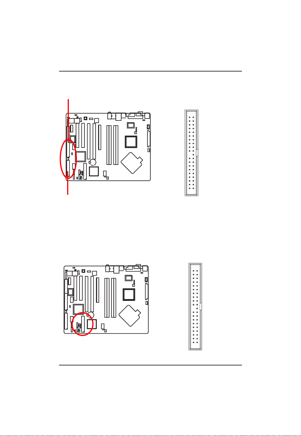
3 /4 ) RAID IDE1/2 (RAID IDE Connectors)
English
These two connectors are for RAID IDE hard disk. The red stripe of the ribbon cable must be the
same side with the Pin1.
RAID IDE1
39 40
RAID IDE2
1
2
5 ) IDE (IDE Connector)
Please connect first hard disk to IDE1. The red stripe of the ribbon cable must be the same side with
the Pin1.
39 40
12
18
Page 19

Connector Introduction
6 ) FDD (Floppy Connector)
Please connect the floppy drive ribbon cables to FDD. It supports 720K,1.2M,1.44M and
2.88Mbytes floppy disk types. The red stripe of the ribbon cable must be the same side with the
Pin1.
1
2
33
34
7/8 ) F_USB1/F_USB2 (Front USB Connector)
Be careful with the polarity of the front panel USB connector. Check the pin assignment while you
connect the front panel USB cable. Please contact your nearest dealer for optional front panel
USB cable.
F_USB1
F_USB2
19
1
2
910
Pin No. Definition
1 Power
2 Power
3 USB DX4 USB Dy5 USB DX+
6 USB Dy+
7 GND
8 GND
9NC
10 NC
Page 20

GA-4KXSV-RH Motherboard
9/10/11/12 ) S_ATA1/ 2/ 3/ 4 (Serial ATA Connectors)
English
You can connect the Serial ATA device to this connector, it provides you high speed transfer rates
(150MB/sec).
SATA3
SATA1
SATA2
13 ) COMB
SATA4
7
1
9
10
2
1
Pin No. Definition
1 GND
2TXP
3 TXN
4 GND
5 RXN
6 RXP
7 GND
Pin No. Definition
1 DCD2 SIN2
3 SOUT2
4 DTR25 GND
6 DSR27 RTS28 CTS29 RI210 NC
20
Page 21

Connector Introduction
14) CD_IN (CD In Connector)
Connect CD-ROM or DVD-ROM audio out to the connector.
Pin No. Definition
1 CD-L
2 GND
3 GND
1
4 CD-R
15) F_AUDIO (Front Audio Connector)
If you want to use Front Audio connector , you must remove 5-6, 9-10 Jumper.
In order to utilize the front audio header, your chassis must have front audio connector . Also please
make sure the pin assigment on the cable is the same as the pin assigment on the MB header. To
find out if the chassis you are buying support front audio connector, please contact your dealer.
Please note, you can have the alternative of using front audio connector or of using rear audio
connector to play sound.
21
Pin No. Definition
1 MIC_L
2
10
1
9
2 GND
3 MIC_R
4 ACI_DET
5 LINE_R
6 GND
7 F_Audio_JD
8 No Pin
9 LINE_L
10 GND
Page 22

GA-4KXSV-RH Motherboard
16 ) F_Panel1 (2X10 Pins Front Panel connector)
Please connect the power LED, PC speaker, reset switch and power switch of your chassis
front panel to the F_PANEL connector according to the pin assignment above.
English
Speaker Connector
SPEAK-
19
20
Reset Switch
SPEAK+
NC
RES-
MSGMSG+
Message LED/
Power/
Sleep LED
2
HDHD+
1
IDE Hard Disk
Active LED
HD (IDE Hard Disk Active LED) Pin 1: LED anode(+)
(Blue) Pin 2: LED cathode(-)
SPEAK (Speaker Connector) Pin 1: VCC(+)
(Amber) Pin 2- Pin 3: NC
Pin 4: Data(-)
RES (Reset Switch) Open: Normal Operation
(Green) Close: Reset Hardware System
PW (Soft Power Connector) Open: Normal Operation
(Red) Close: Power On/Off
MSG(Message LED/ Power/ Sleep LED) Pin 1: LED anode(+)
(Yellow) Pin 2: LED cathode(-)
NC (Purple) NC
RES+
22
Page 23

Connector Introduction
17)IR_CIR
Make sure the pin 1 on the IR device is aling with pin one the connector. T o enable the IR function
on the board, you are required to purchase an option IR module. T o use IR function only, please
connect IR module to Pin1 to Pin5.
Pin No. Definition
1 VCC(5V)
2 Pin Removed
3 IRRX
4 GND
5 IRTX
18) PWR_LED
PWR_LED is connect with the system power indicator to indicate whether the system is on/off.
It will blink when the system enters suspend mode. If you use dual color LED, power LED will turn
to another color.
23
Pin No. Definition
1
1 MPD+
2 MPD3 MPD-
Page 24

GA-4KXSV-RH Motherboard
19 )CPU_FAN (CPU Fan Connector)
English
20) PWR_FAN (Power Fan Connector)
Please note, a proper installation of the CPU cooler is essential to prevent the CPU from running
under abnormal condition or damaged by overheating.The CPU fan connector supports Max.
current up to 1A .
Pin No. Definition
1
This connector allows you to link with the cooling fan on the system case to lower the system
temperature.
1 GND
2 12V
3 Sense
4 Control
24
1
Pin No. Definition
1 GND
2 +12V
3 Sense
Page 25

Connector Introduction
21) SYS_FAN (System Fan Connector)
This connector allows you to link with the cooling fan on the system case to lower the system
temperature.
1
Pin No. Definition
1 GND
2 +12V
3 Sense
22) NB_FAN (Chip Fan Connector)
If you installed wrong direction, the chip fan will not work. Sometimes will damage the chip fan.
(Usually black cable is GND)
1
Pin No. Definition
1 +12V
2 GND
25
Page 26

GA-4KXSV-RH Motherboard
23 ) BAT1 (Battery)
English
If you want to erase CMOS...
1.Turn OFF the computer and unplug the power cord.
2.Remove the battery, wait for 30 second.
3.Re-install the battery.
4.Plug the power cord and turn ON the computer.
CAUTION
Danger of explosion if battery is incorrectly
replaced.
Replace only with the same or equivalent
type recommended by the manufacturer.
Dispose of used batteries according to the
manufacturer’s instructions.
26
Page 27

2- 6: Jumper Setting
Jumper Setting
3
1
7
6
4
8
5
2
1 ) RUSB_PSEL 5 ) JP1
2 ) FUSB_PSEL 6 ) JP2
3 ) SUS_CLK 7 ) JP5
4 ) CLR_CMOS 8 ) JP6
27
Page 28

GA-4KXSV-RH Motherboard
1 / 2 ) FUSB_PSEL/RUSB_PSEL (F_USB1 connector USB power source selection)
RUSB_PSEL
English
FUSB_PSEL
3 ) SUS_CLK (TPM clock selection)
1-2 close: P5V_DUAL
1
2-3 close: P5V (Default value)
1
1
1-2 close: P5V_DUAL
1
2-3 close: P5V (Default value)
1
1-2 close: South Bridge (Deault value)
28
1
2-3 close: Crystal
Page 29

Jumper Setting
4 ) CLR_CMOS (Clear CMOS Function)
Y ou may clear the CMOS data to its default values by this jumper.
Default value doesn’t include the “Shunter” to prevent from improper use this jumper. To
clear CMOS, temporarily short 1-2 pin.
1-2 close: Clear CMOS
1
2-3 close: Normal (Default)
1
29
Page 30

GA-4KXSV-RH Motherboard
5 / 6 / 7 / 8 ) JP1/JP2/JP5/JP6 (PCI-X Bus Speedy Function)
English
JP5
JP1
JP2 JP6
PCI-X1
JP1 1. PCI
2. PCI-X 66MHz
JP2 3. PCI-X 100MHz
4. PCI 33MHz
PCI-X Compatibility
PCI-X 133MHz/100MHz 1 OPEN 2 OPEN
PCI-X 66MHz 1 OPEN 2 CLOSE
PCI 1 CLOSE 2 DON’T CARE
133MHZ Enabled
PCI-X 133MHz 3 OPEN
PCI-X 100MHz 3 CLOSE
66MHz Enabled
PCI 66MHz 4 OPEN
PCI 33MHz 4 CLOSE
30
PCI-X2
JP5 1. PCI
2. PCI-X 66MHz
JP6 3. PCI-X 100MHz
4. PCI 33MHz
Page 31

2- 7: Block Diagram
Motherboard Block Diagram
Clock Generator
ICS954148
Onboard VGA
PCI Express
PCIE x16
USB Ports 0~7
PCI Express
PCIE x1
TEKOR 8257E
Intel 6700 PXH
PCIE-PCIX Bridge
AC97/
Azalia ALC880
PCIE Bus
PCIE Bus
AC97 Link
Intel Pentium4
LGA775
GMCH
(Lakeport)
945G
DMI
Hub Link
ICH7R
PCI Bus
PCI Slot 1,2
TPM SLD9630
Front Panel/
CPU Fan
VID0~4
DDRII SDRAM DIMMx2
DDRII SDRAM DIMMx2
PCI Bus
IDE Bus
ITE8212 RAID
IDE Primary
SATA Bus
LPC Bus
Serial ATA
Dual BIOS
LPC I/O ITE8712G
COMA COMB LPT
PWM/Other
Power
Channel A
Channel B
I/O Ports:
PS/2 FDD
Audio Ports: Front Audio
LIN_OUT LINE_IN MIC
TELE CD_IN AUX_IN
31
Page 32

Page 33

BIOS Setup
Chapter 3 BIOS Setup
BIOS (Basic Input and Output System) includes a CMOS SETUP utility which allows user to
configure
required settings or to activate certain system features.
The CMOS SETUP saves the configuration in the CMOS SRAM of the motherboard.
When the power is turned off, the battery on the motherboard supplies the necessary power to the
CMOS SRAM.
When the power is turned on, pushing the <Del> button during the BIOS POST (Power-On Self Test)
will take you to the CMOS SETUP screen. You can enter the BIOS setup screen by pressing "Ctrl
+ F1".
When setting up BIOS for the first time, it is recommended that you save the current BIOS to a disk
in the event that BIOS needs to be reset to its original settings. If you wish to upgrade to a new
BIOS, either
Gigabyte's Q-Flash or @BIOS utility can be used.
Q-Flash allows the user to quickly and easily update or backup BIOS without entering the operating
system.
@BIOS is a Windows-based utility that does not require users to boot to DOS before upgrading BIOS
but directly download and update BIOS from the Internet.
CONTROL KEYS
< >< >< >< > Move to select item
<Enter> Select Item
<Esc> Main Menu - Quit and not save changes into CMOS Status Page Setup Menu
and Option Page Setup Menu - Exit current page and return to Main Menu
<Page Up> Increase the numeric value or make changes
<Page Down> Decrease the numeric value or make changes
<F1> General help, only for Status Page Setup Menu and Option Page Setup Menu
<F2> Item Help
<F5> Restore the previous CMOS value from CMOS, only for Option Page Setup Menu
<F6> Load the file-safe default CMOS value from BIOS default table
<F7> Load the Optimized Defaults
<F8> Dual BIOS/Q-Flash utility
<F9> System Information
<F10> Save all the CMOS changes, only for Main Menu
Main Menu
The on-line description of the highlighted setup function is displayed at the bottom of the screen.
Status Page Setup Menu / Option Page Setup Menu
Press F1 to pop up a small help window that describes the appropriate keys to use and the
possible selections for the highlighted item. To exit the Help Window press <Esc>.
33
Page 34

GA-4KXSV-RH Motherboard
The Main Menu
Once you enter Award BIOS CMOS Setup Utility, the Main Menu (as figure below) will appear on the
screen. Use arrow keys to select among the items and press <Enter> to accept or enter the sub-menu.
CMOS Setup Utility-Copyright (C) 1984-2005 Award Software
` Standard CMOS Features
` Advanced BIOS Features
` Integrated Peripherals
` Power Management Setup
` PnP/PCI Configurations
` PC Health Status
` Frequency/Voltage Control
ESC: Quit KLJI: Select Item
F8: Dual BIOS1/Q-Flash F10: Save & Exit Setup
Time, Date, Hard Disk Type...
If you can't find the setting you want, please press "Ctrl+F1" to search the advanced option
hidden.
Please Load Optimized Defaults in the BIOS when somehow the system works not stable as
usual. This action makes the system reset to the default for stability.
Standard CMOS Features
This setup page includes all the items in standard compatible BIOS.
Advanced BIOS Features
This setup page includes all the items of Award special enhanced features.
Integrated Peripherals
This setup page includes all onboard peripherals.
Power Management Setup
This setup page includes all the items of Green function features.
PnP/PCI Configuration
This setup page includes all the configurations of PCI & PnP ISA resources.
PC Health Status
This setup page is the System auto detect Temperature, voltage, fan, speed.
Frequency/V oltage Control
This setup page is control CPU clock and frequency ratio.
Load Fail-Safe Defaults
Fail-Safe Defaults indicates the value of the system parameters which the system would be in safe
configuration.
Load Fail-Safe Defaults
Load Optimized Defaults
Set Supervisor Password
Set User Password
Save & Exit Setup
Exit Without Saving
34
Page 35

Load Optimized Defaults
Optimized Defaults indicates the value of the system parameters which the system would be in best
performance configuration.
Set Supervisor Password
Change, set, or disable password. It allows you to limit access to the system and Setup, or just to Setup.
Set User Password
Change, set, or disable password. It allows you to limit access to the system.
Save & Exit Setup
Save CMOS value settings to CMOS and exit setup.
Exit Without Saving
Abandon all CMOS value changes and exit setup.
BIOS Setup
35
Page 36

GA-4KXSV-RH Motherboard
2-1 Standard CMOS Features
CMOS Setup Utility-Copyright (C) 1984-2005 Award Software
Date (mm:dd:yy) Fri, Mar 18 2005
Time (hh:mm:ss) 18:25:04
` IDE Channel 0 Master [None]
` IDE Channel 0 Slave [None]
` IDE Channel 2 Master [None]
` IDE Channel 2 Slave [None]
` IDE Channel 3 Master [None]
` IDE Channel 3 Slave [None]
Drive A [1.44M, 3.5"]
Drive B [None]
Floppy 3 Mode Suport [Disabled]
Halt On [All, But Keyboard]
Base Memory 640K
Extended Memory 511M
KLJI: Move Enter: Select +/-/PU/PD: Value F10: Save ESC: Exit F1: General Help
F5: Previous Values F6: Fail-Safe Defaults F7: Optimized Defaults
Date
The date format is <week>, <month>, <day>, <year>.
Week The week, from Sun to Sat, determined by the BIOS and is display only
Month The month, Jan. Through Dec.
Day The day, from 1 to 31 (or the maximum allowed in the month)
Year The year, from 1999 through 2098
Time
The times format in <hour> <minute> <second>. The time is calculated base on the 24-hour
military-time clock. For example, 1 p.m. is 13:00:00.
IDE Channel 0/2/3 Master, Slave
IDE HDD Auto-Detection Press "Enter" to select this option for automatic device detection.
IDE Chaneel 0 Master: You can use one of three methods:
Auto Allows BIOS to automatically detect IDE devices during POST(default)
None Select this if no IDE devices are used and the system will skip the automatic
detection step and allow for faster system start up.
Manual User can manually input the correct settings
Access Mode Use this to set the access mode for the hard drive. The four options are:
CHS/LBA/Large/Auto(default:Auto)
Capacity Capacity of currently installed hard disk.
Hard drive information should be labeled on the outside drive casing. Enter the appropriate option
based on this information.
Cylinder Number of cylinders
Head Number of heads
Precomp Write precomp
Standard CMOS Features
36
Item Help
Menu Level`
Change the day, month,
year
<Week>
Sun. to Sat.
<Month>
Jan. to Dec.
<Day>
1 to 31 (or maximum
allowed in the month)
<Year>
1999 to 2098
Page 37

Landing Zone Landing zone
Sector Number of sectors
Drive A / Drive B
The category identifies the types of floppy disk drive A or drive B that has been installed in the
computer.
None No floppy drive installed
360K, 5.25" 5.25 inch PC-type standard drive; 360K byte capacity.
1.2M, 5.25" 5.25 inch AT-type high-density drive; 1.2M byte capacity
(3.5 inch when 3 Mode is Enabled).
720K, 3.5" 3.5 inch double-sided drive; 720K byte capacity
1.44M, 3.5" 3.5 inch double-sided drive; 1.44M byte capacity.
2.88M, 3.5" 3.5 inch double-sided drive; 2.88M byte capacity.
Floppy 3 Mode Support (for Japan Area)
Disabled Normal Floppy Drive. (Default value)
Drive A Drive A is 3 mode Floppy Drive.
Drive B Drive B is 3 mode Floppy Drive.
Both Drive A & B are 3 mode Floppy Drives.
Halt on
The category determines whether the computer will stop if an error is detected during power up.
No Errors The system boot will not stop for any error that may be detected and you
will be prompted.
All Errors Whenever the BIOS detects a non-fatal error the system will be stopped.
All, But Keyboard The system boot will not stop for a keyboard error; it will stop for all other
errors. (Default value)
All, But Diskette The system boot will not stop for a disk error; it will stop for all other errors.
All, But Disk/Key The system boot will not stop for a keyboard or disk error; it will stop for all
other errors.
Memory
The category is display-only which is determined by POST (Power On Self Test) of the BIOS.
Base Memory
The POST of the BIOS will determine the amount of base (or conventional) memory installed
in the system.
The value of the base memory is typically 512K for systems with 512K memory installed on
the motherboard, or 640K for systems with 640K or more memory installed on the motherboard.
Extended Memory
The BIOS determines how much extended memory is present during the POST.
This is the amount of memory located above 1 MB in the CPU's memory address map.
Total Memory
This item displays the memory size that used.
BIOS Setup
37
Page 38

GA-4KXSV-RH Motherboard
2-2 Advanced BIOS Features
CMOS Setup Utility-Copyright (C) 1984-2005 Award Software
` Hard Disk Boot Priority [Press Enter]
First Boot Device [Floppy]
Second Boot Device [Hard Disk]
Third Boot Device [CDROM]
Password Check [Setup]
# CPU Hyper-Threading [Enabled]
Limit CPUID Max. to 3 [Disabled]
No-Execute Memory Protect
CPU Enhanced Halt (C1E)
CPU Thermal Monitor 2(TM2)
CPU EIST Function
On-Chip Frame Buffer Size [8MB]
KLJI: Move Enter: Select +/-/PU/PD: Value F10: Save ESC: Exit F1: General Help
F3: Language1 F5: Previous Values F6: Fail-Safe Defaults F7: Optimized Defaults
(Note)
(Note)
(Note)
" # " System will detect automatically and show up when you install the Intel® Pentium® 4
processor with HT Technology.
Hard Disk Boot Priority
Select boot sequence for onboard(or add-on cards) SCSI, RAID, etc.
Use < > or < > to select a device, then press<+> to move it up, or <-> to move it down the list. Press
<ESC> to exit this menu.
First / Second / Third Boot Device
Floppy Select your boot device priority by Floppy.
LS120 Select your boot device priority by LS120.
Hard Disk Select your boot device priority by Hard Disk.
CDROM Select your boot device priority by CDROM.
ZIP Select your boot device priority by ZIP.
USB-FDD Select your boot device priority by USB-FDD.
USB-ZIP Select your boot device priority by USB-ZIP.
USB-CDROM Select your boot device priority by USB-CDROM.
USB-HDD Select your boot device priority by USB-HDD.
LAN Select your boot device priority by LAN.
Disabled Select your boot device priority by Disabled.
Password Check
Setup The system will boot but will not access to Setup page if the correct
password is not entered at the prompt. (Default value)
System The system will not boot and will not access to Setup page if the correct
password is not entered at the prompt.
If you want to cancel the setting of password, please just press ENTER to make [SETUP] empty.
(Note) This item will show up when you install a processor which supports this function.
Advanced BIOS Features
(Note)
[Enabled]
[Enabled]
[Enabled]
[Enabled]
Item Help
Menu Level`
Select Hard Disk Boot
Device Priority
38
Page 39

BIOS Setup
CPU Hyper-Threading
Enabled Enables CPU Hyper Threading Feature. Please note that this feature is only working
for operating system with multi processors mode supported. (Default value)
Disabled Disables CPU Hyper Threading.
Limit CPUID Max. to 3
Enabled Limit CPUID Maximum value to 3 when use older OS like NT4.
Disabled Disables CPUID Limit for windows XP. (Default value)
No-Execute Memory Protect
(Note)
Enabled Enables No-Execute Memory Protect function. (Default value)
Disabled Disables No-Execute Memory Protect function.
CPU Enhanced Halt (C1E)
(Note)
Enabled Enables CPU Enhanced Halt (C1E) function. (Default value)
Disabled Disables CPU Enhanced Halt (C1E) function.
CPU Thermal Monitor 2 (TM2)
(Note)
Enabled Enable CPU Thermal Monitor 2 (TM2) function. (Default value)
Disabled Disable CPU Thermal Monitor 2 (TM2) function.
CPU EIST Function
(Note)
Enabled Enable CPU EIST function. (Default value)
Disabled Disable EIST function.
On-Chip Frame Buffer Size
1MB Set On-chip frame buffer size to 1MB.
8MB Set On-chip frame buffer size to 8MB. (Default value)
(Note) This item will show up when you install a processor which supports this function.
39
Page 40

GA-4KXSV-RH Motherboard
2-3 Integrated Peripherals
CMOS Setup Utility-Copyright (C) 1984-2005 Award Software
On-Chip Primary PCI IDE [Enabled]
SATA RAID/AHCI Mode [Disabled]
On-Chip SATA Mode [Auto]
x PATA IDE Set to Ch.0 Master/Slave
SATA Port 0/2 Set to Ch.2 Master/Slave
SATA Port 1/3 Set to Ch.3 Master/Slave
USB Controller [Enabled]
USB 2.0 Controller [Enabled]
USB Keyboard Support [Disabled]
USB Mouse Support [Disabled]
Legacy USB Storage detect [Enabled]
Azalia Codec [Auto]
Onboard H/W GigaRAID [Enabled]
GigaRAID Function [RAID]
Onboard H/W LAN [Enabled]
Onboard LAN Boot ROM [Disabled]
Onboard Serial Port 1 [3F8/IRQ4]
Onboard Serial Port 2 [2F8/IRQ3]
KLJI: Move Enter: Select +/-/PU/PD: Value F10: Save ESC: Exit F1: General Help
F5: Previous Values F6: Fail-Safe Defaults F7: Optimized Defaults
Integrated Peripherals
Item Help
Menu Level`
CMOS Setup Utility-Copyright (C) 1984-2005 Award Software
Onboard Parallel Port [378/IRQ7]
Parallel Port Mode [SPP]
x ECP Mode Use DMA 3
KLJI: Move Enter: Select +/-/PU/PD: Value F10: Save ESC: Exit F1: General Help
F5: Previous Values F6: Fail-Safe Defaults F7: Optimized Defaults
Integrated Peripherals
Item Help
Menu Level`
On-Chip Primary PCI IDE
Enabled Enable onboard 1st channel IDE port. (Default value)
Disabled Disable onboard 1st channel IDE port.
40
Page 41

BIOS Setup
SATA RAID / AHCI Mode
RAID Set the onboard SATA controller to RAID mode.
AHCI Set the onboard SATA controller to AHCI mode. Advanced Host
Controller Interface (AHCI) is an interface specification that allows the
storage driver to enable advanced Serial ATA features such as Native
Command Queuing and hot plug. For more details about AHCI, please
visit Intel's website.
Disabled Set the onboard SATA controller to IDE mode. (Default value)
On-Chip SATA Mode
Disabled Disable this function.
Auto BIOS will auto detect. (Default value)
Combined Set On-Chip SATA mode to Combined, you can use up to 4 HDDs on
the motherboard; 2 for SATA and the other for PATA IDE.
Enhanced Set On-Chip SATA mode to Enhanced, the motherboard allows up to 6
HDDs to use.
Non-Combined Set On-Chip SATA mode to Non-Combined, SATA will be simulated to
PATA mode.
PATA IDE Set to
Ch.1 Master/Slave Set PATA IDE to Ch. 1 Master/Slave. (Default value)
Ch.0 Master/Slave Set PATA IDE to Ch. 0 Master/Slave.
SATA Port 0/2 Set to
This value will auto make by the setting "On-Chip SATA Mode" and "PATA IDE Set to".
If PATA IDE were set to Ch. 1 Master/Slave,this function will auto set to Ch. 0 Master/Slave.
SATA Port 1/3 Set to
This value will auto make by the setting "On-Chip SATA Mode" and "PATA IDE Set to".
If PATA IDE were set to Ch. 0 Master/Slave,this function will auto set to Ch. 1 Master/Slave.
USB Controller
Enabled Enable USB Controller. (Default value)
Disabled Disable USB Controller.
USB 2.0 Controller
Disable this function if you are not using onboard USB 2.0 feature.
Enabled Enable USB 2.0 Controller. (Default value)
Disabled Disable USB 2.0 Controller.
USB Keyboard Support
Enabled Enable USB Keyboard Support.
Disabled Disable USB Keyboard Support. (Default value)
USB Mouse Support
Enabled Enable USB Mouse Support.
Disabled Disable USB Mouse Support. (Default value)
Legacy USB Storage detect
Enabled Enable legacy USB storage detect. (Default value)
Disabled Disable legacy USB storage detect.
41
Page 42

GA-4KXSV-RH Motherboard
Azalia Codec
Auto Auto detect Azalia audio function. (Default value)
Disabled Disable Azalia audio function.
Onboard H/W GigaRAID
Enabled Enable Onboard H/W GigaRAID function. (Default value)
Disabled Disable this function.
GigaRAID Function
RAID Select onboard GigaRAID chip function as RAID. (Default value)
ATA Select onboard GigaRAID chip function asa ATA.
Onboard H/W LAN
Enabled Enable Onboard H/W LAN function. (Default value)
Disabled Disable this function.
Onboard Onboard LAN Boot ROM
Enabled Enable Onboard Onboard LAN Boot ROM function.
Disabled Disable this function. (Default value)
Onboard Serial Port 1
Auto BIOS will automatically setup the port 1 address.
3F8/IRQ4 Enable onboard Serial port 1 and address is 3F8/IRQ4. (Default value)
2F8/IRQ3 Enable onboard Serial port 1 and address is 2F8/IRQ3.
3E8/IRQ4 Enable onboard Serial port 1 and address is 3E8/IRQ4.
2E8/IRQ3 Enable onboard Serial port 1 and address is 2E8/IRQ3.
Disabled Disable onboard Serial port 1.
Onboard Serial Port 2
Auto BIOS will automatically setup the port 1 address.
3F8/IRQ4 Enable onboard Serial port 2 and address is 3F8/IRQ4.
2F8/IRQ3 Enable onboard Serial port 2 and address is 2F8/IRQ3. (Default value)
3E8/IRQ4 Enable onboard Serial port 2 and address is 3E8/IRQ4.
2E8/IRQ3 Enable onboard Serial port 2 and address is 2E8/IRQ3.
Disabled Disable onboard Serial port 2.
Onboard Parallel port
Disabled Disable onboard LPT port.
378/IRQ7 Enable onboard LPT port and address is 378/IRQ7. (Default value)
278/IRQ5 Enable onboard LPT port and address is 278/IRQ5.
3BC/IRQ7 Enable onboard LPT port and address is 3BC/IRQ7.
Parallel Port Mode
SPP Using Parallel port as Standard Parallel Port. (Default value)
EPP Using Parallel port as Enhanced Parallel Port.
ECP Using Parallel port as Extended Capabilities Port.
ECP+EPP Using Parallel port as ECP & EPP mode.
ECP Mode Use DMA
3 Set ECP Mode Use DMA to 3. (Default value)
1 Set ECP Mode Use DMA to 1.
42
Page 43

2-4 Power Management Setup
CMOS Setup Utility-Copyright (C) 1984-2005 Award Software
ACPI Suspend Type [S1(POS)]
Soft-Off by PWR-BTTN [Instant-off]
PME Event Wake Up [Enabled]
Power On by Ring [Enabled]
Resume by Alarm [Disabled]
x Date (of Month) Alarm Everyday
x Time (hh:mm:ss) Alarm 0 : 0 : 0
Power On By Mouse [Disabled]
Power On By Keyboard [Disabled]
x KB Power ON Password Enter
AC Back Function [Soft-Off]
KLJI: Move Enter: Select +/-/PU/PD: Value F10: Save ESC: Exit F1: General Help
F5: Previous Values F6: Fail-Safe Defaults F7: Optimized Defaults
ACPI Suspend Type
S1(POS) Set ACPI suspend type to S1/POS(Power On Suspend). (Default value)
S3(STR) Set ACPI suspend type to S3/STR(Suspend To RAM).
Soft-off by PWR-BTTN
Instant-off Press power button then Power off instantly. (Default value)
Delay 4 Sec. Press power button 4 sec. to Power off. Enter suspend if button is pressed
less than 4 sec.
PME Event Wake Up
Disabled Disable this function.
Enabled Enable PME Event Wake up. (Default value)
Power On by Ring
Disabled Disable Power on by Ring function.
Enabled Enable Power on by Ring function. (Default value)
Resume by Alarm
You can set "Resume by Alarm" item to enabled and key in Date/time to power on system.
Disabled Disable this function. (Default value)
Enabled Enable alarm function to POWER ON system.
If Resume by Alarm is Enabled.
Date (of Month) Alarm : Everyday, 1~31
Time (hh: mm: ss) Alarm : (0~23) : (0~59) : (0~59)
Power On By Mouse
Disabled Disabled this function. (Default value)
Double Click Double click on PS/2 mouse left button to power on the system.
Power Management Setup
Item Help
Menu Level`
BIOS Setup
Only for GA-8I945G Pro.
43
Page 44

GA-4KXSV-RH Motherboard
Power On By Keyboard
Password Enter from 1 to 5 characters to set the Keyboard Power On Password.
Disabled Disabled this function. (Default value)
Keyboard 98 If your keyboard have "POWER Key" button, you can press the key to
power on the system.
KB Power ON Password
When "Power On by Keyboard" set at Password, you can set the password here.
Enter Input password (from 1 to 5 characters) and press Enter to set the Keyboard
Power On password.
AC Back Function
Soft-Off When AC-power back to the system, the system will be in "Off" state.
(Default value)
Full-On When AC-power back to the system, the system always in "On" state.
Memory When AC-power back to the system, the system will return to the Last state
before AC-power off.
44
Page 45

2-5 PnP/PCI Configurations
CMOS Setup Utility-Copyright (C) 1984-2005 Award Software
PCI 1 IRQ Assignment [Auto]
PCI 2 IRQ Assignment [Auto]
KLJI: Move Enter: Select +/-/PU/PD: Value F10: Save ESC: Exit F1: General Help
F3: Language1 F5: Previous Values F6: Fail-Safe Defaults F7: Optimized Defaults
PCI 1 IRQ Assignment
Auto Auto assign IRQ to PCI 1. (Default value)
3,4,5,7,9,10,11,12,14,15 Set IRQ 3,4,5,7,9,10,11,12,14,15 to PCI 1.
PCI 2 IRQ Assignment
Auto Auto assign IRQ to PCI 2. (Default value)
3,4,5,7,9,10,11,12,14,15 Set IRQ 3,4,5,7,9,10,11,12,14,15 to PCI 2.
PnP/PCI Configurations
Menu Level`
Item Help
BIOS Setup
Only for GA-8I945G Pro.
45
Page 46

GA-4KXSV-RH Motherboard
2-6 PC Health Status
CMOS Setup Utility-Copyright (C) 1984-2005 Award Software
Vcore OK
VCC18 OK
+3.3V OK
+5V OK
+12V OK
5VSB OK
Current CPU Temperature 47oC
Current CPU FAN Speed RPM
Current POWER FAN Speed RPM
Current SYSTEM FAN Speed RPM
CPU Warning Temperature [Disabled]
CPU FAN Fail Warning [Disabled]
POWER FAN Fail Warning [Disabled]
SYSTEM FAN Fail Warning [Disabled]
CPU Smart FAN Control [Enabled]
CPU Smart FAN Mode [Auto]
KLJI: Move Enter: Select +/-/PU/PD: Value F10: Save ESC: Exit F1: General Help
F5: Previous Values F6: Fail-Safe Defaults F7: Optimized Defaults
Current Voltage(V) Vcore / VCC18V / +3.3V / +5V / +12V / 5VSB
Detect system's voltage status automatically.
Current CPU Temperature
Detect CPU temperature automatically.
Current CPU/POWER/SYSTEM FAN Speed (RPM)
Detect CPU/POWER/SYSTEM Fan speed status automatically.
CPU Warning Temperature
60oC / 140oF Monitor CPU temperature at 60oC / 140oF.
70oC / 158oF Monitor CPU temperature at 70oC / 158oF.
80oC / 176oF Monitor CPU temperature at 80oC / 176oF.
90oC / 194oF Monitor CPU temperature at 90oC / 194oF.
Disabled Disable this function. (Default value)
CPU/POWER /SYSTEM FAN Fail Warning
Disabled Fan warning function disable. (Default value)
Enabled Fan warning function enable.
CPU Smart FAN Control
Disabled Disable this function.
Enabled When this function is enabled, CPU fan will run at different speed depending on
CPU temperature. Users can adjust the fan speed with Easy Tune based on
their requirements.
PC Health Status
Menu Level`
Item Help
46
Page 47

BIOS Setup
CPU Smart FAN Mode
This option is available only when CPU Smart FAN Control is enabled.
Auto BIOS autodetects the type of CPU fan you installed and sets the optimal CPU
Smart FAN control mode for it. (Default Value)
Voltage Set to Voltage when you use a CPU fan with a 3-pin fan power cable.
PWM Set to PWM when you use a CPU fan with a 4-pin fan power cable.
Note: In fact, the Voltage option can be used for CPU fans with 3-pin or 4-pin power cables.
However, some 4-pin CPU fan power cables are not designed following Intel 4-Wire fans PWM
control specifications. With such CPU fans, selecting PWM will not effectively reduce the fan
speed.
47
Page 48

GA-4KXSV-RH Motherboard
2-7 Frequency/Voltage Control
CMOS Setup Utility-Copyright (C) 1984-2005 Award Software
Robust Graphics Booster [Auto]
C.A.M [High]
CPU Host Clock Control [Disabled]
x CPU Host Frequency (Mhz) 200
System Memory Multiplier [Auto]
x Memory Frequency (Mhz) 667
KLJI: Move Enter: Select +/-/PU/PD: Value F10: Save ESC: Exit F1: General Help
F5: Previous Values F6: Fail-Safe Defaults F7: Optimized Defaults
Wrong frequency may cause system can’t boot. Clear CMOS will overcome wrong
frequency setting issue.
Robust Graphics Booster
Select the options can enhance the VGA graphics card bandwidth to get higher performance.
Auto Set Robust Graphics Booster to Auto. (Default value)
Fast Set Robust Graphics Booster to Fast.
Turbo Set Robust Graphics Booster to Turbo.
C.A.M
High Set clock ratio for frequency-locked CPU to High. (Default value)
Low Set clock ratio for frequency-locked CPU to Low.
CPU Host Clock Control
Please note that if your system is overclocked and cannot restart, please wait 20secs.
for automatic system restart or clear the CMOS setup data and perform a safe restart.
Disabled Disable CPU Host Clock Control. (Default value)
Enabled Enable CPU Host Clock Control.
CPU Host Frequency (Mhz)
100MHz ~ 600MHz Set CPU Host Frequency from 100MHz to 600MHz.
If you use FSB533 Pentium 4 processor, please set "CPU Host Frequency" to 133MHz.If you use
FSB800 Pentium 4 processor, please set "CPU Host Frequency" to 200MHz.
Incorrect using it may cause your system broken. For power End-User use only!
Auto Set Memory frequency by DRAM SPD data. (Default value)
MB Intelligent Tweaker(M.I.T.)
Item Help
Menu Level`
48
Page 49

BIOS Setup
System Memory Multiplier
Wrong frequency may make system can't boot, clear CMOS to overcome wrong frequency issue.
for FSB(Front Side Bus) frequency=533MHz,
3 Memory Frequency = Host clock X 3.
4 Memory Frequency = Host clock X 4.
Auto Set Memory frequency by DRAM SPD data. (Default value)
for FSB(Front Side Bus) frequency=800MHz,
2.0 Memory Frequency = Host clock X 2.0.
2.66 Memory Frequency = Host clock X 2.66.
3.33 Memory Frequency = Host clock X 3.33.
Auto Set Memory frequency by DRAM SPD data. (Default value)
for FSB(Front Side Bus) frequency=1066MHz,
1.5 Memory Frequency = Host clock X 1.5.
2.0 Memory Frequency = Host clock X 2.0.
2.5 Memory Frequency = Host clock X 2.5.
Auto Set Memory frequency by DRAM SPD data. (Default value)
Memory Frequency (Mhz)
The values depend on CPU Host Frequency (Mhz) and System Memory Multiplier setting.
49
Page 50

GA-4KXSV-RH Motherboard
2-8 Load Fail-Safe Defaults
CMOS Setup Utility-Copyright (C) 1984-2005 Award Software
` Standard CMOS Features
` Advanced BIOS Features
` Integrated Peripherals
` Power Management Setup
` PnP/PCI Configurations
` PC Health Status
` Frequency/Voltage Control
ESC: Quit KLJI: Select Item
F8: Dual BIOS1/Q-Flash F10: Save & Exit Setup
Load Fail-Safe Defaults (Y/N)? N
Load Fail-Safe Defaults
Load Fail-Safe Defaults
Load Optimized Defaults
Set Supervisor Password
Set User Password
Save & Exit Setup
Exit Without Saving
Fail-Safe defaults contain the most appropriate values of the system parameters that allow minimum
system performance.
2-9 Load Optimized Defaults
CMOS Setup Utility-Copyright (C) 1984-2005 Award Software
` Standard CMOS Features
` Advanced BIOS Features
` Integrated Peripherals
` Power Management Setup
` PnP/PCI Configurations
` PC Health Status
` Frequency/Voltage Control
ESC: Quit KLJI: Select Item
F8: Dual BIOS1/Q-Flash F10: Save & Exit Setup
Load Optimized Defaults (Y/N)? N
Load Optimized Defaults
Load Fail-Safe Defaults
Load Optimized Defaults
Set Supervisor Password
Set User Password
Save & Exit Setup
Exit Without Saving
Selecting this field loads the factory defaults for BIOS and Chipset Features which the system
automatically detects.
50
Page 51

BIOS Setup
2-10 Set Supervisor/User Password
CMOS Setup Utility-Copyright (C) 1984-2005 Award Software
` Standard CMOS Features
` Advanced BIOS Features
` Integrated Peripherals
` Power Management Setup
` PnP/PCI Configurations
` PC Health Status
` Frequency/Voltage Control
ESC: Quit KLJI: Select Item
F8: Dual BIOS1/Q-Flash F10: Save & Exit Setup
Enter Password:
Change/Set/Disa ble Password
When you select this function, the following message will appear at the center of the screen to
assist you in creating a password.
Type the password, up to eight characters, and press <Enter>. You will be asked to confirm the
password. Type the password again and press <Enter>. You may also press <Esc> to abort the
selection and not enter a password.
To disable password, just press <Enter> when you are prompted to enter password. A message
"PASSWORD DISABLED" will appear to confirm the password being disabled. Once the password
is disabled, the system will boot and you can enter Setup freely.
The BIOS Setup program allows you to specify two separate passwords:
SUPERVISOR PASSWORD and a USER PASSWORD. When disabled, anyone may access all
BIOS Setup program function. When enabled, the Supervisor password is required for entering the
BIOS Setup program and having full configuration fields, the User password is required to access
only basic items.
If you select "System" at "Password Check" in Advance BIOS Features Menu, you will be
prompted for the password every time the system is rebooted or any time you try to enter Setup
Menu.
If you select "Setup" at "Password Check" in Advance BIOS Features Menu, you will be prompted
only when you try to enter Setup.
Load Fail-Safe Defaults
Load Optimized Defaults
Set Supervisor Password
Set User Password
Save & Exit Setup
Exit Without Saving
51
Page 52

GA-4KXSV-RH Motherboard
2- 11 Save & Exit Setup
CMOS Setup Utility-Copyright (C) 1984-2005 Award Software
` Standard CMOS Features
` Advanced BIOS Features
` Integrated Peripherals
` Power Management Setup
` PnP/PCI Configurations
` PC Health Status
` Frequency/Voltage Control
ESC: Quit KLJI: Select Item
F8: Dual BIOS1/Q-Flash F10: Save & Exit Setup
Save to CMOS and EXIT (Y/N)? Y
Save Data to CMOS
Load Fail-Safe Defaults
Load Optimized Defaults
Set Supervisor Password
Set User Password
Save & Exit Setup
Exit Without Saving
Type "Y" will quit the Setup Utility and save the user setup value to RTC CMOS.
Type "N" will return to Setup Utility.
2-12 Exit Without Saving
CMOS Setup Utility-Copyright (C) 1984-2005 Award Software
` Standard CMOS Features
` Advanced BIOS Features
` Integrated Peripherals
` Power Management Setup
` PnP/PCI Configurations
` PC Health Status
` Frequency/Voltage Control
ESC: Quit KLJI: Select Item
F8: Dual BIOS1/Q-Flash F10: Save & Exit Setup
Quit Without Saving (Y/N)? N
Abandon all Data
Load Fail-Safe Defaults
Load Optimized Defaults
Set Supervisor Password
Set User Password
Save & Exit Setup
Exit Without Saving
Type "Y" will quit the Setup Utility without saving to RTC CMOS.
Type "N" will return to Setup Utility.
Only for GA-8I945G Pro.
52
Page 53

INTEL RAID BIOS Configuration
Chapter 4 INTEL RAID BIOS Configuration
Configuring the Intel RAID BIOS
The Intel RAID BIOS setup lets you choose the RAID array type and which hard drives you want to
make part of the array.
Entering the RAID BIOS Setup
1. After rebooting your computer, wait until you see the RAID software prompting you to press Ctrl + I.
The RAID prompt appears as part of the system POST and boot process prior to loading the OS. You
have a few seconds to press Ctrl + I before the window disappears.
Intel(R) Matrix Storage Manager option ROM V5.0.0.1011 ICH7R wRAID5
Copyright(C) 2003-04 Intel Corporation. All Rights Reversed.
RAID Volumes :
None Defined.
Physical Disks :
Port Driver Model Serial # Size Type/Status(Vol ID)
0 ST3120026AS 3JT354CP 111.7GB Non-RAID Disk
1 ST3120026AS 3JT329JX 111.7GB Non-RAID Disk
Press <CTRL - I> to enter Configuration Utility
Press Ctrl + I. The Intel RAID Utility - Create RAID Volume window appears (as illustrated below).
Intel(R) Matrix Storage Manager option ROM V5.0.0.1011 ICH7R wRAID5
Copyright(C) 2003-04 Intel Corporation. All Rights Reversed.
RAID Volumes :
None Defined.
Physical Disks :
Port Driver Model Serial # Size Type/Status(Vol ID)
0 ST3120026AS 3JT329JX 111.7GB Non-RAID Disk
1 ST3120026AS 3JT354CP 111.7GB Non-RAID Disk
[ MAIN MENU ]
1. Create RAID Volume
2. Delete RAID Volume
3. Reset Disks to Non-RAID
4. Exit
[ DISK/VOLUME INFORMATION ]
[KL]-Select [ESC]-Exit [ENTER]-Select Menu
53
Page 54

GA-4KXSV-RH Motherboard
Create RAID Volume
Press Enter under Create RAID Volume to set up RAID.
Intel(R) Matrix Storage Manager option ROM V5.0.0.1011 ICH7R wRAID5
Copyright(C) 2003-04 Intel Corporation. All Rights Reversed.
Enter a string between 1 and 16 characters in length that can be used
to uniquely identify the RAID volume. This name is case sensitive and
[KL]-Change [TAB]-Next [ESC]-Previous Menu [ENTER]-Select
After entering the Create Volume Menu, you can set disk name with 1~16 letters (letters cannot be
special characters) under Name item.
After setting disk name, press Enter to select RAID Level.
Intel(R) Matrix Storage Manager option ROM V5.0.0.1011 ICH7R wRAID5
Copyright(C) 2003-04 Intel Corporation. All Rights Reversed.
RAID0- Data striped across multiple physical drives for performance.
RAID1- Data mirrored across multiple physical drives for redundancy.
RAID0+1- Striped volume whose segments are RAID 1 volumes. Requires
four hard drives. Functionally equivalent to RAID 0+1.
RAID5- Data and parity striped across three or more physical drives
[KL]-Change [TAB]-Next [ESC]-Previous Menu [ENTER]-Select
[ CREATE VOLUME MENU ]
Name : RAID_Volume0
RAID Level : RAID0(Stripe)
Disks : Select Disks
Strip Size : 128KB
Capacity : 223.5 GB
RAID Level : RAID0(Stripe)
Strip Size : 128KB
Capacity : 223.5 GB
Choose the RAID level best suited to your usage model.
for performance and redundancy.
Create Volume
[ HELP ]
can not contain special characters.
[ CREATE VOLUME MENU ]
Name : RAID_Volume0
Disks : Select Disks
Create Volume
[ HELP ]
There are four RAID levels: RAID0(Stripe), RAID1(Mirror), RAID 0+1 (Striping + Mirroring) and RAID5.
After selecting the RAID level, press Enter to select Strip Size.
54
Page 55

INTEL RAID BIOS Configuration
The KB is a unit of Strip Size. You can set disk block size with this item.
The disk block size can be set from 4KB to 128KB. After you set disk block size, press Enter to set
disk Capacity.
Intel(R) Matrix Storage Manager option ROM V5.0.0.1011 ICH7R wRAID5
Copyright(C) 2003-04 Intel Corporation. All Rights Reversed.
[KL]-Change [TAB]-Next [ESC]-Previous Menu [ENTER]-Select
Intel(R) Matrix Storage Manager option ROM V5.0.0.1011 ICH7R wRAID5
Copyright(C) 2003-04 Intel Corporation. All Rights Reversed.
[ CREATE VOLUME MENU ]
Name : RAID_Volume0
RAID Level : RAID0(Stripe)
Disks : Select Disks
Strip Size : 128KB
Capacity : 223.5 GB
RAID Level : RAID0(Stripe)
Strip Size : 128KB
Capacity : 223.5 GB
Create Volume
[ HELP ]
The following are typical values:
RAID 0 - 128KB
RAID 1 - 64KB
RAID 5 - 64KB
[ CREATE VOLUME MENU ]
Name : RAID_Volume0
Disks : Select Disks
Create Volume
[ HELP ]
Enter the volume capacity. The default value indicates the
maximum volume capacity using the selected disks. If less
than the maximum capacity is chosen, creation of a second
volume is needed to utilize the remaining space.
[KL]-Change [TAB]-Next [ESC]-Previous Menu [ENTER]-Select
Press Enter to enter Create Volume after setting disk capacity.
55
Page 56

GA-4KXSV-RH Motherboard
Press Enter under the Create Volume item.
Intel(R) Matrix Storage Manager option ROM V5.0.0.1011 ICH7R wRAID5
Copyright(C) 2003-04 Intel Corporation. All Rights Reversed.
[KL]-Change [TAB]-Next [ESC]-Previous Menu [ENTER]-Select
[ CREATE VOLUME MENU ]
Name : RAID_Volume0
RAID Level : RAID0(Stripe)
Disks : Select Disks
Strip Size : 128KB
Capacity : 223.5 GB
Press "ENTER" to Create the specified volume
Create Volume
[ HELP ]
An alert bar will be displayed warning you that all data on selected disks will be lost. Please press Y
to complete the set-up of RAID.
Intel(R) Matrix Storage Manager option ROM V5.0.0.1011 ICH7R wRAID5
Copyright(C) 2003-04 Intel Corporation. All Rights Reversed.
WARNING : ALL DATA ON SELECTED DISKS WILL BE LOST.
[ CREATE VOLUME MENU ]
Name : RAID_Volume0
RAID Level : RAID0(Stripe)
Disks : Select Disks
Strip Size : 128KB
Capacity : 223.5 GB
Are you sure you want to creat this volume? (Y/N) :
Create Volume
[ HELP ]
Press "ENTER" to Create the specified volume
[KL]-Change [TAB]-Next [ESC]-Previous Menu [ENTER]-Select
56
Page 57

INTEL RAID BIOS Configuration
After the completion, you will see the detailed information about the RAID, such as RAID level, disk
block size, disk name and disk capacity, etc.
Intel(R) Matrix Storage Manager option ROM V5.0.0.1011 ICH7R wRAID5
Copyright(C) 2003-04 Intel Corporation. All Rights Reversed.
RAID Volumes :
ID Name Level Strip Size Status
Bootable
0 RAID_Volume0 RAID(Stripe) 128KB 223.5GB Normal Yes
Physical Disks :
Port Driver Model Serial # Size Type/Status(Vol ID)
0 ST3120026AS 3JT329JX 111.7GB Member Disk(0)
1 ST3120026AS 3JT354CP 111.7GB Member Disk(0)
[KL]-Select [ESC]-Exit [ENTER]-Select Menu
[ MAIN MENU ]
1. Create RAID Volume
2. Delete RAID Volume
3. Reset Disks to Non-RAID
4. Exit
[ DISK/VOLUME INFORMATION ]
Delete RAID Volume
If you want to delete a RAID volume, please select the Delete RAID Volume option. Press Enter key
and follow the instructions on the screen.
Intel(R) Matrix Storage Manager option ROM V5.0.0.1011 ICH7R wRAID5
Copyright(C) 2003-04 Intel Corporation. All Rights Reversed.
RAID Volumes :
ID Name Level Strip Size Status
Bootable
0 RAID_Volume0 RAID(Stripe) 128KB 223.5GB Normal Yes
Physical Disks :
Port Driver Model Serial # Size Type/Status(Vol ID)
0 ST3120026AS 3JT329JX 111.7GB Member Disk(0)
1 ST3120026AS 3JT354CP 111.7GB Member Disk(0)
[ MAIN MENU ]
1. Create RAID Volume
2. Delete RAID Volume
3. Reset Disks to Non-RAID
4. Exit
[ DISK/VOLUME INFORMATION ]
[KL]-Select [ESC]-Exit [ENTER]-Select Menu
57
 Loading...