

GIGABYTE GA-3CCWL-RH, GA-3CCWV-RH Owner's Manual

GA-3CCWV-RH
GA-3CCWL-RH
AMD Socket F Dual Processor Motherboard
USER’S MANUAL
AMD Opteron™ Socket F Dual Processor Motherboard
Rev. 1001
12ME-3CCWVRH-1001R
* The WEEE marking on the product indicates this product must not be disposed of with
user's other household waste and must be handed over to a designated collection point
for the recycling of waste electrical and electronic equipment!!
* The WEEE marking applies only in European Union's member states.

GA-3CCWV-RH/GA-3CCWL-RH Motherboard
Table of Content
English
Item Checklist .........................................................................................4
WARNING!...............................................................................................4
Chapter 1 Introduction............................................................................5
Chapter 2 Hardware Installation Process.............................................12
Chapter 3 BIOS Setup ..........................................................................35
1.1 Features Summary................................................................................ 5
1.2 GA-3CCWV-RH Motherboard Components.......................................... 8
1.3 GA-3CCWL-RH Motherboard Components .......................................10
2-1: Installing Processor and CPU Haet Sink ...........................................12
2-1-1: Installing CPU ....................................................................................................... 12
2-1-2: Installing Heat Sink ............................................................................................... 14
2-2: Install Memory Modules..................................................................... 15
2-3: Connect ribbon cables, cabinet wires, and power supply ................ 18
2-3-1 : I/O Back Panel Introduction................................................................................ 18
2-4: Connectors Introduction..................................................................... 21
2-5: Jumper Setting ...................................................................................31
2-7: Block Diagram...................................................................................34
Main........................................................................................................... 37
Advanced Processor Options ........................................................................................ 40
Advanced ...................................................................................................41
Memory Configuration ..................................................................................................... 42
PCI Configuration............................................................................................................. 43
I/O Device Configuration................................................................................................. 46
Advanced Chipset Control ............................................................................................. 49
Hardware Monitor ............................................................................................................ 51
Security ......................................................................................................54
Server.........................................................................................................56
System Management...................................................................................................... 57
Console Redirection........................................................................................................ 58
Boot............................................................................................................ 61
2

Table of Content
Exit ............................................................................................................. 62
Chapter 4 Application Driver Installation ...............................................67
A.NVDIA Chipset Driver Installation............................................................................... 67
B.Audio Hot Fix Driver Installation ................................................................................. 72
(For Windows 64-bit operating system)........................................................................ 72
C.Realtek ALC883 Audio Driver Installation ................................................................. 76
D.DirectX 9.0 Driver Installation...................................................................................... 78
Chapter 5 Appendix..............................................................................81
Appexdix: PCI-X Card QVL ........................................................................................... 81
English
3
GA-3CCWV-RH/GA-3CCWL-RH Motherboard
Item Checklist
GA-3CCWV-RH motherboard GA-3CCWL-RH Motherborad
English
Serial ATA cable x 6 I/O Shield Kit
IDE (ATA133 ) cable x 1 / Floppy cable x 1 SATA Power cable x 3
CD for motherboard driver & utility
GA-3CCWV-RH/GA-3CCWL-RH user’s manual
Computer motherboards and expansion cards contain very delicate Integrated Circuit (IC) chips. T o
protect them against damage from static electricity, you should follow some precautions whenever you
work on your computer.
WARNING!
1. Unplug your computer when working on the inside.
2. Use a grounded wrist strap before handling computer components. If you do not have
one, touch both of your hands to a safely grounded object or to a metal object, such as
the power supply case.
3. Hold components by the edges and try not touch the IC chips, leads or connectors, or
other components.
4. Place components on a grounded antistatic pad or on the bag that came with the
components whenever the components are separated from the system.
5. Ensure that the A TX power supply is switched of f before you plug in or remove the ATX
power connector on the motherboard.
Installing the motherboard to the chassis…
If the motherboard has mounting holes, but they don’t line up with the holes on the base and there are
no slots to attach the spacers, do not become alarmed you can still attach the spacers to the mounting
holes. Just cut the bottom portion of the spacers (the spacer may be a little hard to cut off, so be careful
of your hands). In this way you can still attach the motherboard to the base without worrying about short
circuits. Sometimes you may need to use the plastic springs to isolate the screw from the motherboard
PCB surface, because the circuit wire may be near by the hole. Be careful, don’t let the screw contact
any printed circuit write or parts on the PCB that are near the fixing hole, otherwise it may damage the
board or cause board malfunctioning.
4

Introduction
Chapter 1 Introduction
1.1 Features Summary
Form Factor y 12” x 10.5” CEB form factor, 8 layers PCB.
CPU y Support Dual AMD OpteronTM Dual Core Processors (Socket F)
y The HyperTransport link of the AMD Opteron processor is capable
of operating at 400, 800, 1200, and 1600 MT/s.
y Supports L2/3 Cache with 1MB/2MB
®
Chipset y NVIDIA
y NEC
Memory y 8 x DDRII DIMM sockets
y Supports up to 32GB 533/667 memory
y Dual Channel memory bus
y ECC Registered DDRII 533/667
y Supports 512MB, 1GB, 2GB and 4GB memory
I/O Control y ITE IT8716F Super I/O
Expansion Slots y 1 PCI slots 32-Bit/33MHz (5V)
(GA-3CCWV-RH) y 1 PCI-Express x8 slot
y 1 PCI-X slot (by NEC UDP 702404 PCI-X bridge)
Expansion Slots y 1 PCI slots 32-Bit/33MHz (5V)
(GA-3CCWL-RH) y 1 PCI-Express x8 slot
y 1 PCI-Express x4 slot
SATA RAID Controller y Built in NVIDIA ® MCP55 Pro with Software RAID 0,1,0+1, 5
y Supports 6 SATA 3.0 Gb/s connectors
On-Board Audio y VISTA premium
On-Board Peripherals y 1 A T A 100 connector
y 1 Floppy connector
y 6 SAT A 3.0 Gb/s connectors
y 2 PS/2 connectors
y 1 Parallel port supports Normal/EPP/ECP mode
y 1 Serial port (COM)
y 10 x USB 2.0 (6 by cable)
y 2 x LAN RJ45
y 6 x Audio ports (4 x Line-out/ 1 x Line-in/ 1 x MIC)
y 2 x SPDIF Out (Optical + Coaxial)
NFP3600 Chipset
®
UDP 702404 (For GA-3CCWV-RH Only)
1 PCI-Express x16 slot (Supports LSI graphics card)
1 PCI-Express x16 slot (Supports LSI graphics card)
5

GA-3CCWV-RH/GA-3CCWL-RH Motherboard
Hardware Monitor y Enhanced features with CPU Vcore, 1.5V reference,
English
On-Board LAN y Dual Marvell® 88E1116 GbE PHY
BIOS y Phoenix BIOS on 8Mb flash ROM
Additional Features y PS/2 Mouse wake up from S1 under Windows Operating System
VCC3 (3.3V) , VBAT3V, +5VSB, CPUA/B Temperature, and
System T emperature V alues viewing
y CPU/Power/System Fan Revolution Detect
y CPU shutdown when overheat
y System Voltage Detect
y Supports WOL, PXE
y External Modem wake up
y Supports S1, S4, S5 under Windows Operating System
y Wake on LAN (WOL)
y Wake on Ring (WOR)
y AC Recovery
y Supports Console Redirection
y Supports 4-pin Fan controller
6

GA-3CCWV-RH/GA-3CCWL-RH Motherboard
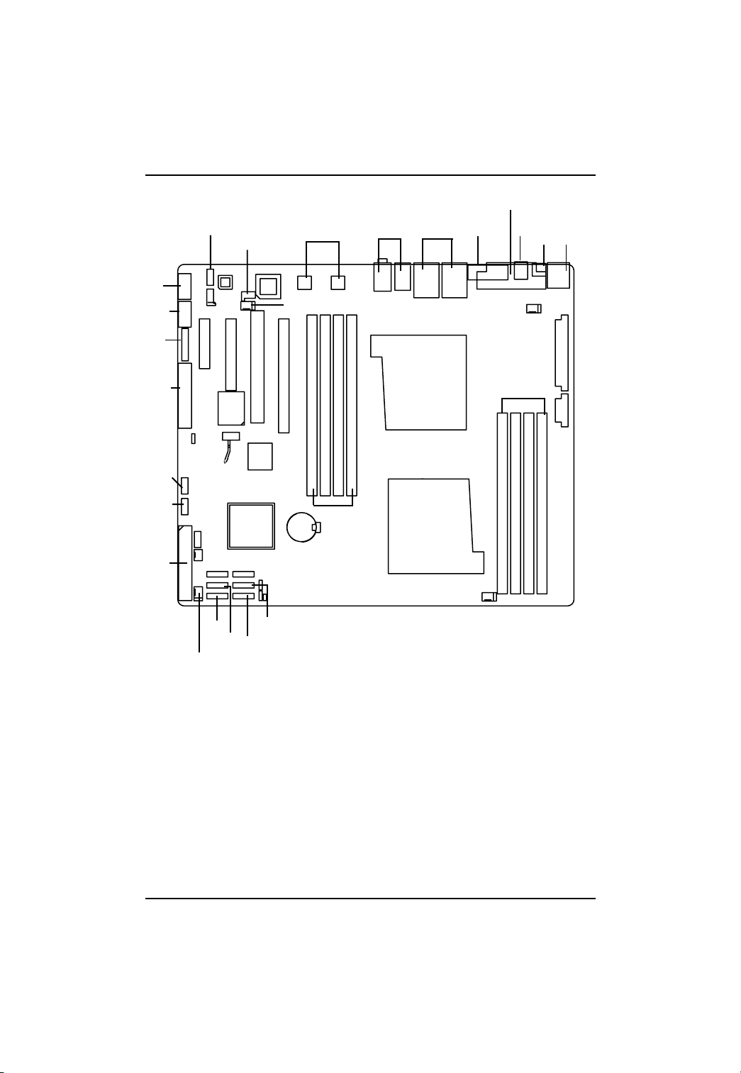
1.2 GA-3CCWV-RH Motherboard Components
1. Primary CPU 24. SATA5 Connector
English
2. Secondary CPU 25. SATA6 Connector
3. NVIDIA 26.
4. 27. Front Fan Connector
5. BIOS Flash 28. Rear Fan Connector
6. ITE IT8716F 29. CPU0 Fan Connector
7. Realtek ALC 883 30. CPU1 Fan Connector
8. Marvell 88E1116 31. PCI-E x4 Slot
9. IDE Connector 32. PCI-X Slot (64bit/133MHz)
10. Floppy Connector 33. PCI Slot(32bit/33MHz)
11. Front Panel Connector 34. PCI-E x16 Slot
12. 1394a Connector 35. DIMMA1/B1/A2/B2 (CPU0)
13. 1394a Connector 36. DIMMA1/B1/A2/B2 (CPU1)
14. Front USB1 Connector 37. Audio Connectors
15. Front USB2 Connector 38. RJ45 Lan Ports/USB Ports
16. Front USB3 Connector 39. COM Port
17. CD IN 40. Parallel Port
18. Front Audio Connector 41. SPDIF out ( )
19. SPDIF In 42. SPDIF out (
20. SATA1 Connector 43. PS/2 Connectors
21. SATA2 Connector 44. Auxiliary Power (ATX1)
22. SAT A3 Connector 45. Auxiliary Power (A TX 12V)
23. SATA4 Connector 46. Battery
)
8

40
Introduction
13
12
11
10
15
16
18
19
8
37
3938
41
42
43
7
17
31
28
3332
34
30
44
2
35
6
5
4
36
3
46
1
45
14
9
26
20
23
29
27
22
24
21
25
9
GA-3CCWV-RH/GA-3CCWL-RH Motherboard
1.3 GA-3CCWL-RH Motherboard Components
1. Primary CPU 24. SATA5 Connector
English
2. Secondary CPU 25. SATA6 Connector
3. NVIDIA 26.
4. BIOS Flash 27. Front Fan Connector
5. Battery 28. Rear Fan Connector
6. ITE IT8716F 29. CPU0 Fan Connector
7. Realtek ALC 883 30. CPU1 Fan Connector
8. Marvell 88E1116 31. PCI-E x8 Slot
9. IDE Connector 32. PCI-E x8 Slot
10. Floppy Connector 33. PCI Slot(32bit/33MHz)
11. Front Panel Connector 34. PCI-E x16 Slot
12. 1394a Connector 35. DIMMA1/B1/A2/B2 (CPU0)
13. 1394a Connector 36. DIMMA1/B1/A2/B2 (CPU1)
14. Front USB1 Connector 37. Audio Connectors
15. Front USB2 Connector 38. RJ45 Lan Ports/USB Ports
16. Front USB3 Connector 39. COM Port
17. CD IN 40. Parallel Port
18. Front Audio Connector 41. SPDIF out ( )
19. SPDIF In 42. SPDIF out (
20. SATA1 Connector 43. PS/2 Connectors
21. SATA2 Connector 44. Auxiliary Power (ATX1)
22. SAT A3 Connector 45. Auxiliary Power (A TX 12V)
23. SATA4 Connector
)
10
40
Introduction
13
18
19
8
37
3938
41
42
43
7
17
12
11
31
10
6
28
3332
34
30
44
2
35
45
4
16
15
14
3
36
5
1
26
9
20
23
29
21
24
25
22
27
11

GA-3CCWV-RH/GA-3CCWL-RH Motherboard
Chapter 2 Hardware Installation Process
2-1: Installing Processor and CPU Haet Sink
English
2-1-1: Installing CPU
Step 1 Raise the metal locking lever on the socket.
Step 2 Remove the plastic covering on the CPU socket.
Step 3 Insert the CPU with the correct orientation. The CPU only fits in one orientation.
Step 4 Once the CPU is properly placed, please replace the plastic covering and push the metal
Before installing the processor and cooling fan, adhere to the following
cautions:
1. The processor will overheat without the heatsink and/or fan, resulting in permanent
irreparable damage.
2. Never force the processor into the socket.
3. Apply thermal grease on the processor before placing cooling fan.
4. Please make sure the CPU type is supported by the motherboard.
5. If you do not match the CPU socket Pin 1 and CPU cut edge well, it will cause
improper installation. Please change the insert orientation.
lever back into locked position.
12

Hardware Installation Process
Step 4. When the processor installation is completed, apply thermal grease to the processor(as
prior to installing the heatsink. AMD recommends using a high thermal conductivity grease
for the thermal interface material rather than a phase change material.
Phase change materials develop strong adhesive forces between the heatsink and
processor.
Removing the heatsink under such conditions can cause the processor to be
removed from the socket without moving the socket lever to the unlocked
position and then damage the processor pins or socket contacts.
** We recommend you to apply the thermal tape to provide better heat conduction between
your CPU and heatsink. (The CPU cooling fan might stick to the CPU due to the
hardening of the thermal paste. During this condition if you try to remove the cooling fan,
you might pull the processor out of the CPU socket alone with the cooling fan, and might
damage the processor.
T o avoid this from happening, we suggest you to either use thermal tape instead of thermal
paste, orremove the cooling fan with extreme caution)
13
GA-3CCWV-RH/GA-3CCWL-RH Motherboard
2-1-2: Installing Heat Sink
Step 1. Attach th cooling fan clip to the processor scoket. Align the heatsink assembly with the
English
Step 2. Coonect the processor fan cable to the processor fan connector.
support frame mating with the backer plate standoffs as shown in Figure 5&6.
NOTE: We recommend you to buy the type of cooling fan which is shown in Figure 7.
This type of cooling fan will provide the best performance for heat releasing.
14
GA-3CCWV-RH/GA-3CCWL-RH Motherboard
2-2: Install Memory Modules
English
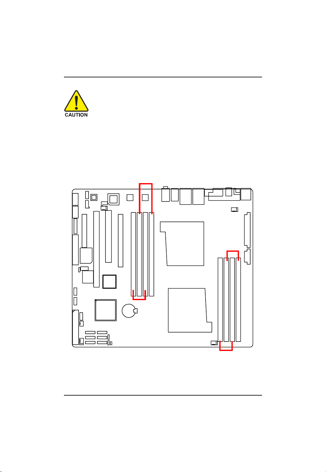
The motherboard has 8 dual inline memory module (DIMM) sockets. The BIOS will automatically
detects memory type and size. To install the memory module, just push it vertically into the DIMM
socket .The DIMM module can only fit in one direction due to the notch. Memory size can vary
between sockets.
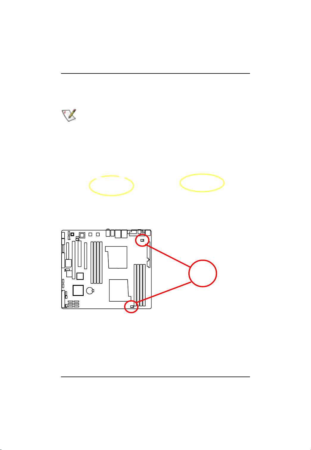
Before installing the processor and heatsink, adhere to the following warning:
When DIMM LED is ON, do not install/remove DIMM from socket.
Channel A (Red)
Channel B (Yellow)
Channel B
(Yellow)
Channel A (Red)
15
Hardware Installation Process
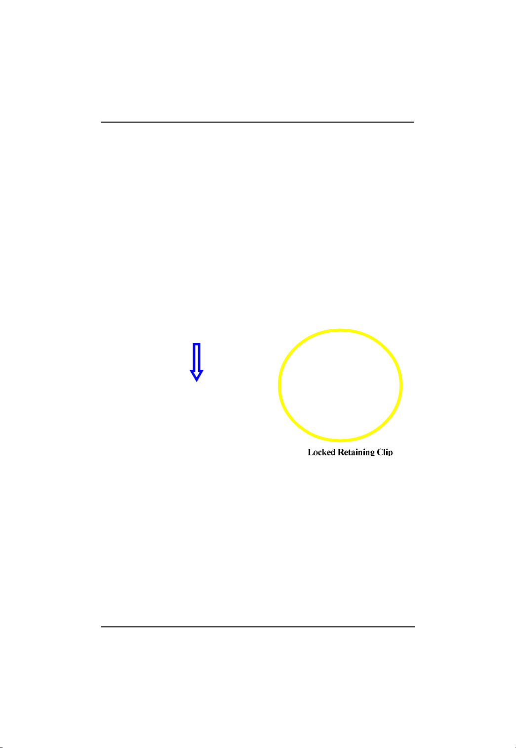
Installation Step:
1. Unlock a DIMM socket by pressing the retaining clips outwards.
2. Aling a DIMM on the socket such that the notch on the DIMM exactly match the notches in the
socket. Firmly insert the DIMMinto the socket until the retaining clips snap back in place.
3. The processor supports 64-bit mode and 128-bit mode configuration of the DIMMs. In 64 bit mode,
only DIMM 0 and 2 can be populated. Possible combinations of DIMMs in 64 bit mode are listed in
T able 1. In 128 bit mode, minimum of two DIMMs is required to create the 128 bit bus; therefore,
DIMMs can only be populated in even numbered pairs in slot 0 & 1, and 2& 3. Each logical DIMM
must be madeof two identical DIMMs having the same device size on each and the same DIMM
size. Regardless of mode, DIMM must be populated in order starting at the farest slotfrom the
processor. Table 2 & 3 shows the possible combination of DIMMs for 128 mode. Not all possbile
combinations are listed in the tables.
4. Installed DIMMs must be the same speed and must all be registered. For a list of suuported
memrory, please refer to the table of previous page.
5. Reverse the installation steps when you wish to remove the DIMM module.
16
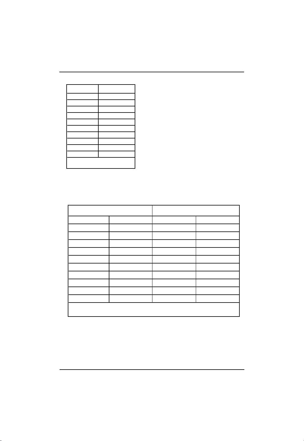
Table 1. Vaild DIMM Configuration for 64 bit Mode
DIMM 0 (MB) DIMM 2 (MB)
X 256
256 256
X 512
512 512
X 1024
1024 1024
X 2048
2048 2048
X 4096
4096 4096
Note: X = Do not populate
Table 2. Vaild DIMM Configuration for 128 bit Mode
Logical DIMM 0 Ligical DIMM1
DIMM 0 (MB) DIMM 1 (MB) DIMM 2 (MB) DIMM 3 (MB)
X X 256 256
256 256 256 256
X X 512 512
512 512 512 512
X X 1024 1024
1024 1024 1024 1024
X X 2048 2048
2048 2048 2048 2048
X X 4096 4096
4096 4096 4096 4096
Note: X = Do Not populate
Hardware Installation Process
17
GA-3CCWV-RH/GA-3CCWL-RH Motherboard
2-3: Connect ribbon cables, cabinet wires, and power
supply
English
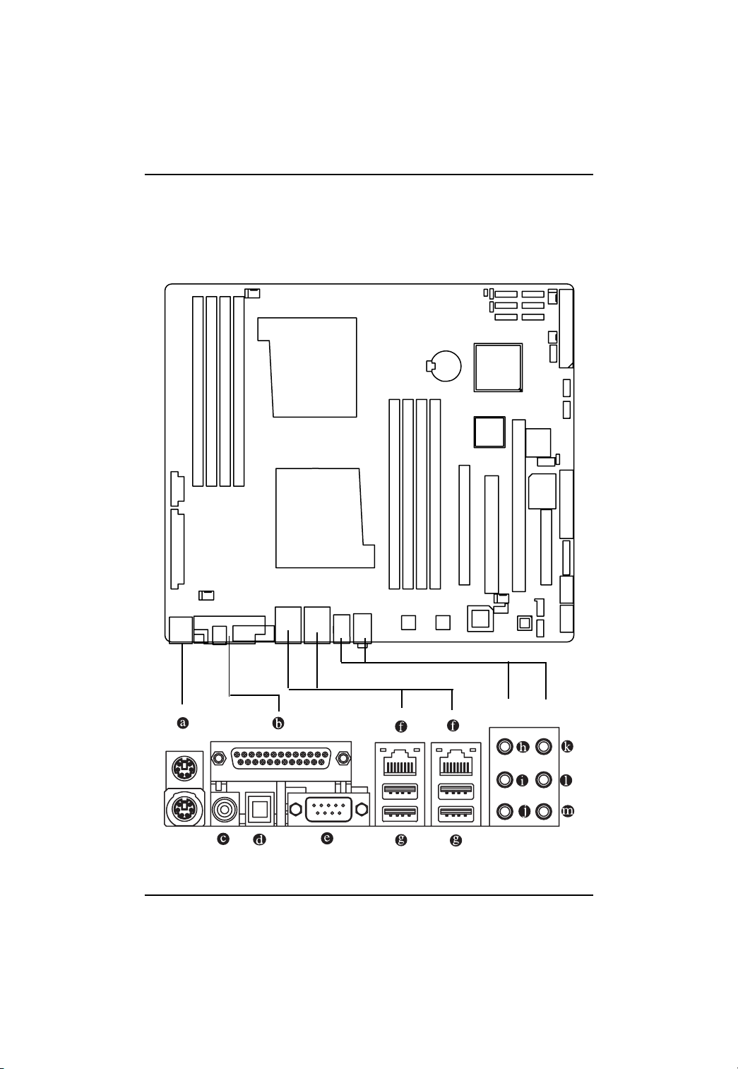
2-3-1 : I/O Back Panel Introduction
18

Hardware Installation Process
PS/2 Keyboard and PS/2 Mouse Connector
To install a PS/2 port keyboard and mouse, plug the mouse to the upper port (green) and the
keyboard to the lower port (purple).
Parallel Port
The parallel port allows connection of a printer, scanner and other peripheral devices.
COAXIAL (SPDIF Out)
The SPDIF coaxial output port is capable for providing digital audio to external speakers or
compressed AC3 data to an external Dolby Digital Decoder via a coaxial cable.
OPTICAL (SPDIF Out)
The SPDIF optical output port is capable for providing digital audio to external speakers or
com-pressed AC3 data to an external Dolby Digital Decoder via an optical cable.
Serial Port
Modem can be connected to Serial port.
LAN Port
The provided Internet connection is Gigabit Ethernet, providing data transfer speeds of
10/100/1000Mbps.
USB Port
Before you connect your device(s) into USB connector(s), please make sure your device(s)
such as USB keyboard, mouse, scanner, zip, speaker...etc. have a standard USB interface.
Also make sure your OS supports USB controller. If your OS does not support USB controller,
please contact OS vendor for possible patch or driver updated. For more information please
contact your OS or device(s) vendors.
Line In
The default Line In jack. Devices like CD-ROM, walkman etc. can be connected to Line In jack.
Line Out (Front Speaker Out)
The default Line Out (Front Speaker Out) jack. Stereo speakers, earphone or front surround
speakers can be connected to Line Out (Front Speaker Out) jack.
MIC In
The default MIC In jack. Microphone must be connected to MIC In jack.
Surround Speaker Out (Rear Speaker Out)
The default Surround Speaker Out (Rear Speaker Out) jack. Rear surround speakers can be
connected to Surround Speaker Out (Rear Speaker Out) jack.
Center/Subwoofer Speaker Out
The default Center/Subwoofer Speaker Out jack. Center/Subwoofer speakers can be connected
to Center/Subwoofer Speaker Out jack.
Side Speaker Out
The default Side Speaker Out jack. Surround side speakers can be connected to Side Speaker
Out jack.
19
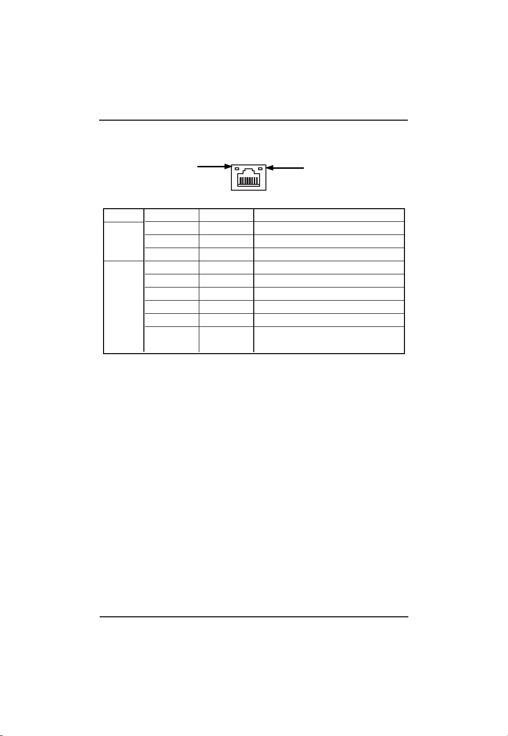
LAN LED Description
Hardware Installation Process
LED2 (Green/Yellow)
Name
LED1
Color Condition Description
Green ON LAN Link / no Access
Green BLINK LAN Access
- OFF Idle
LED2
- OFF 10Mbps connection
Green BLINK Port identification with 10 Mbps connection
Green ON 100Mbps connection
Green BLINK Port identification with 100Mbps connection
Yellow ON 1Gbps connection
Yellow BLINK Port identification with 1Gbps connection
LED1 (Green)
20
GA-3CCWV-RH/GA-3CCWL-RH Motherboard
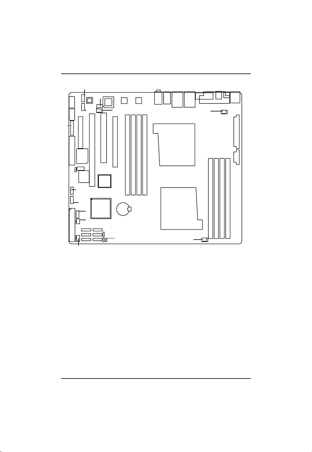
2-4: Connectors Introduction
English
16
15
14
17
19
18
4
13
24
21
1
2
12
11
22
3
5
8
6
9
10
7
23
1. ATX1 15. F1_1394 (IEEE 1394 connector)
2. ATX2 16. F2_1394 (IEEE 1394 connector)
3. IDE 17. F_Audio (Front Audio Connector)
4. FDD (Floppy Connector) 18. CD_IN
5. SA TA 1 (SATA Connector) 19 . SPDIF_IN
6. SA TA 2 (SATA Connector) 2 0. CPU0_FAN(CPU0 Fan Connector)
7. SA TA 3 (SATA Connector) 2 1. CPU1_FAN(CPU1 Fan Connector)
8. SA TA 4 (SATA Connector) 22. MCP55_FAN (NB Fan Connector)
9. SA TA 5 (SATA Connector) 23. FRONT_FAN
10. SATA 6 (SATA Connector) 24. REAR_FAN
11. F_USB1 (Front USB Connector) 25. BATTERY
12. F_USB2 (Front USB Connector) 26. CI
13. F_USB3 (Front USB Connector)
14. F_Panel (Front Panel Connector)
26
25
20
21
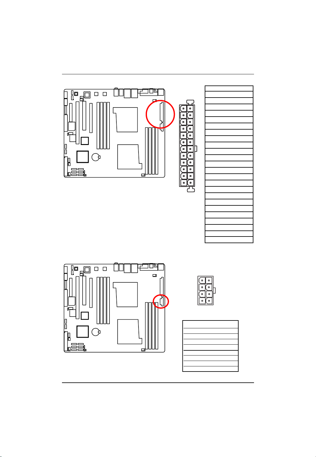
1) ATX1 (Auxukiary Power Connector)
AC power cord should only be connected to
your power supply unit after A TX power cable
and other related devices are firmly connected
to the mainboard.
Connector Introduction
PIN No. Definition
1 +3.3V
24
12
1
13
2 +3.3V
3 GND
4 +5V
5 GND
6 +5V
7 GND
8 POK
9 5VSB
10 +12V
11 +12V
12 +3.3V
13 +3.3V
14 -12V
15 GND
16 PSON
17 GND
18 GND
19 GND
20 -5V
21 +5V
22 +5V
23 +5V
24 GND
2 ) ATX2 (Auxukiary +12V Power Connector)
This connector (A TX +12V) is used only for
CPU Core Voltage.
22
8
4
1
5
Pin No. Definition
1 GND
2 GND
3 GND
4 GND
5 P12V_CPU1
6 P12V_CPU1
7 P12V_CPU0
8 P12V_CPU0
GA-3CCWV-RH/GA-3CCWL-RH Motherboard
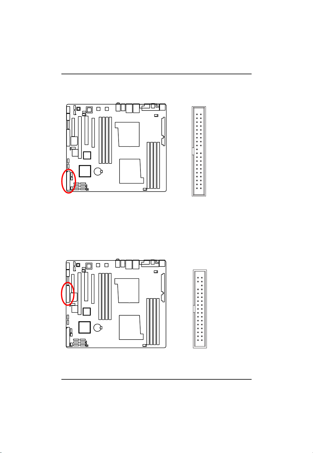
3 ) IDE (IDE Connector)
English
Please connect first harddisk to IDE1. The red stripe of the ribbon cable must be the same side with
the Pin1.
1
39
2
40
4 ) FDD (Floppy Connector)
Please connect the floppy drive ribbon cables to FDD. It supports 720K,1.2M,1.44M and
2.88Mbytes floppy disk types. The red stripe of the ribbon cable must be the same side with the
Pin1.
2
1
34
33
23
GA-3CCWV-RH/GA-3CCWL-RH Motherboard
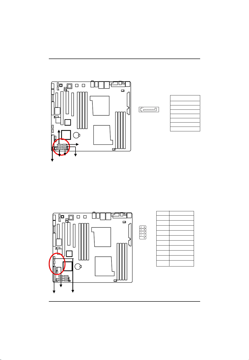
5/ 6/ 7/ 8/9/10 ) SATA 1~6 (Serial ATA Connectors)
English
SATA2
11/ 12/13 ) F_USB1/2/3 (Front USB Connectors)
Y ou can connect the Serial A T A device to this connector , it provides you high speed transfer rates
(3.0 Gb/sec).
Pin No. Definition
1 GND
2 TXP
1
SATA1
7
3 TXN
4 GND
5 RXN
6 RXP
7 GND
SATA4
SATA6
SATA3
SATA5
Be careful with the polarity of the front USB connector. Check the pin assignment carefully while
you connect the front USB cable, incorrect connection between the cable and connector will make
the device unable to work or even damage it. For optional front USB cable, please contact your
local dealer.
Pin No. Definition
12
10
9
1 Power
2 Power
3 USB Dx4 USB Dy5 USB Dx+
6 USB Dy+
7 GND
8 GND
9 No Pin
10 N C
F_USB1
F_USB2
F_USB3
24
Connector Introduction
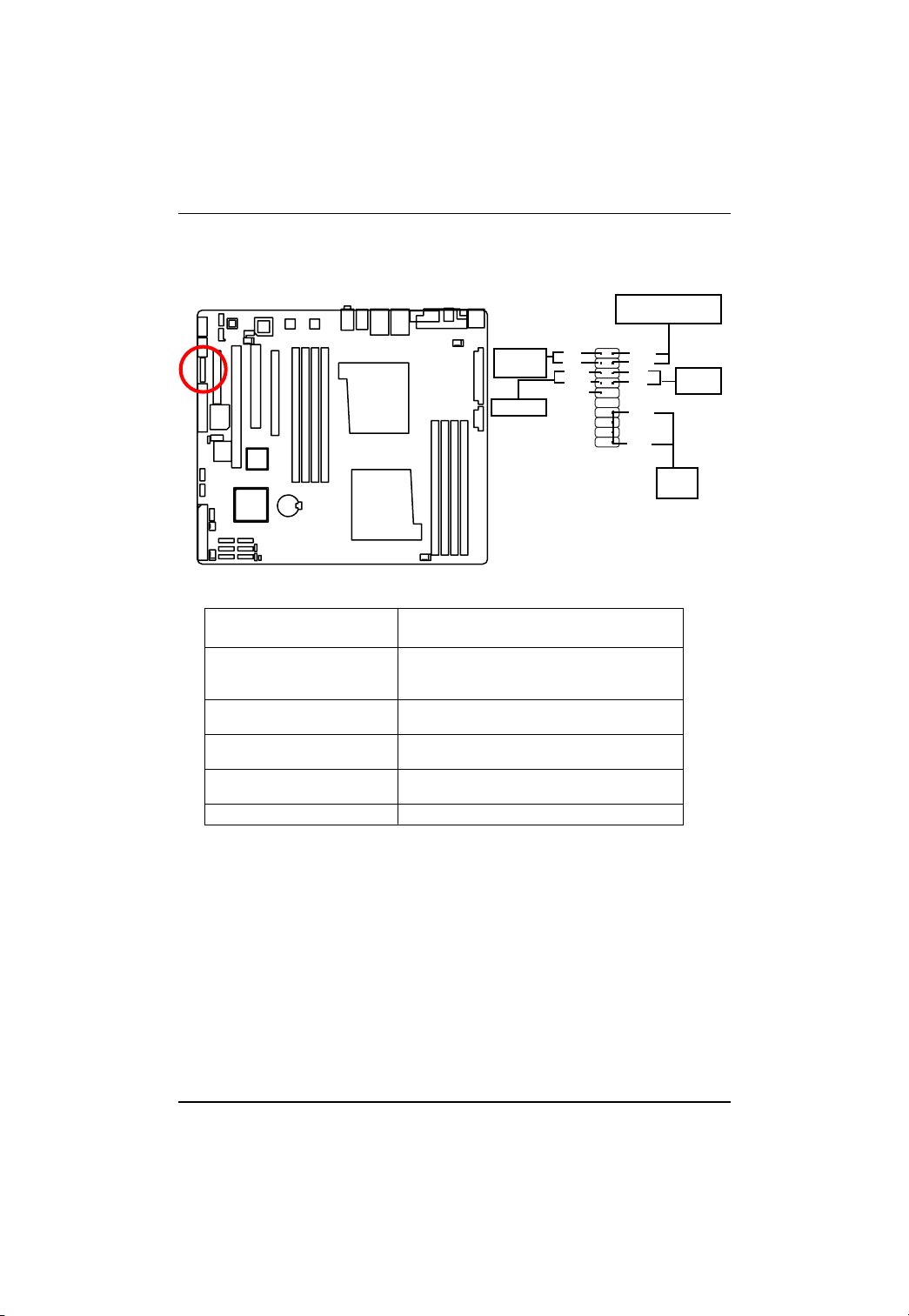
14 ) F_Panel (2X10 Pins Front Panel connector)
Please connect the power LED, PC speaker, reset switch and power switch of your chassis
front panel to the F_PANEL connector according to the pin assignment above.
Message LED/Power/Sleep
LED
2
1
IDE Hard Disk
Active LED
Reset Switch
HD (IDE Hard Disk Active LED) Pin 1: LED anode(+)
Pin 2: LED cathode(-)
SPK (Speaker Connector) Pin 1: VCC(+)
Pin 2- Pin 3: NC
Pin 4: Data(-)
RES (Reset Switch) Open: Normal Operation
Close: Reset Hardware System
PW (Soft Power Connector) Open: Normal Operation
Close: Power On/Off
MSG(Message LED/Power/ Pin 1: LED anode(+)
Sleep LED) Pin 2: LED cathode(-)
NC NC
HD+
HD-
RSE+
RSE-
NC
MSG+
MSGPW+
PW-
SPK+
SPK-
19
20
Speaker
Connector
Soft Power
Connector
25
GA-3CCWV-RH/GA-3CCWL-RH Motherboard
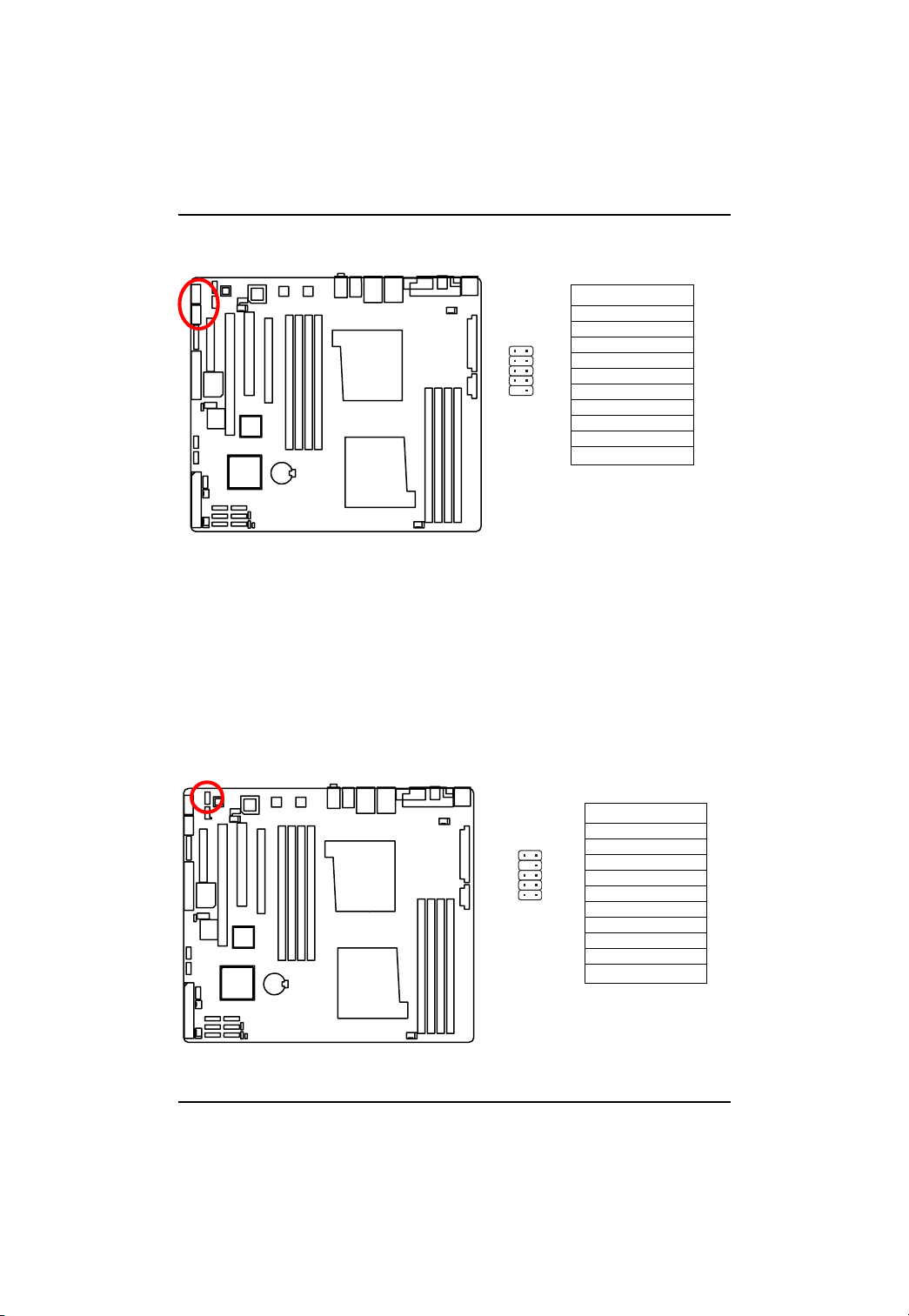
15/16 ) F1_1394/F2_1394 (IEEE 1394 connectors)
English
17) F_AUDIO (Front AUDIO Connector)
Pin No. Definition
1 FTPA1+
1
2
10
9
2 FTPA13 GND
4 GND
5 FTPB1+
6 FTPB17 BUSVCC0
8 BUSVCC0
9 No Pin
10 N C
If you want to use Front Audio connector , you must remove 5-6, 9-10 Jumper . In order to utilize the
front audio header, your chassis must have front audio connector . Also please make sure the pin
assigment on the cable is the same as the pin assigment on the MB header. To find out if the chassis
you are buying support front audio connector, please contact your dealer.
26
Pin No. Definition
910
12
1 MIC
2 GND
3 REF
4 POWER
5 FrontAudio(R)
6 RearAudio(R)
7 Reserved
8 No Pin
9 FrontAudio (L)
10 RearAudio(L)
 Loading...