

Page 1

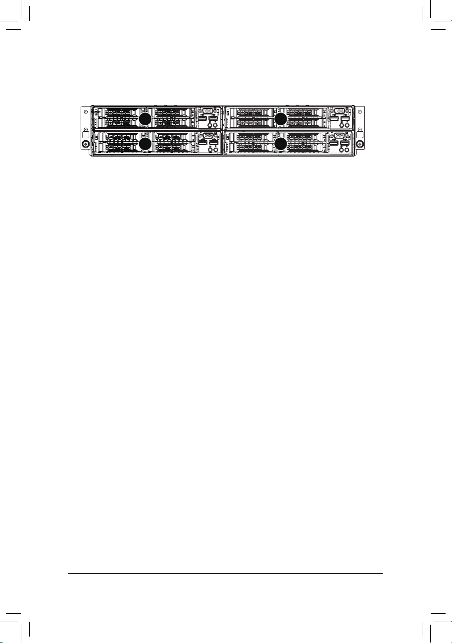
G210-H4G
Four hot-pluggable systems (nodes)
Dual LGA1150 socket motherboard for Intel® Xeon® series processors
Service Guide
Rev. 1.0
Page 2

Copyright
© 2014 GIGA-BYTE TECHNOLOGY CO., LTD. All rights reserved.
The trademarks mentioned in this manual are legally registered to their respective owners.
Disclaimer
Information in this manual is protected by copyright laws and is the property of GIGABYTE.
Changes to the specifications and features in this manual may be made by GIGABYTE
without prior notice. No part of this manual may be reproduced, copied, translated, transmitted, or
published in any form or by any means without GIGABYTE's prior written permission.
Documentation Classications
In order to assist in the use of this product, GIGABYTE provides the following types of documentations:
For detailed product information, carefully read the Serice Guide.
For product-related information, check on our website at:
http://www.gigabyte.com
Page 3

Preface
Before using this information and the product it supports, please read the following general infor-
mation.
1. This Service Guide provides you with all technical information relating to the BASIC CON-
FIGURATION decided for GIGABYTE’s “global” product offering. To better t local market-
requirements and enhance product competitiveness, your regional ofce MAY have decided
toextend the functionality of a machine (e.g. add-on card, modem, or extra memory capabil-
ity).These LOCALIZED FEATURES will NOT be covered in this generic service guide. In
suchcases, please contact your regional ofces or the responsible personnel/channel to
provide youwith further technical details.
2. Please note WHEN ORDERING SPARE PARTS, you should check the most up-to-date
informationavailable on your regional web or channel. For whatever reason, if a part num-
ber change is made,it will not be noted in the printed Service Guide. For GIGABYTE-AU-
THORIZED SERVICEPROVIDERS, your GIGABYTE ofce may have a DIFFERENT part
number code to thosegiven in the FRU list of this printed Service Guide. You MUST use the
list provided by yourregional GIGABYTE ofce to order FRU parts for repair and service of
customer machines.
Page 4

Table of Contents
Box Contents ...................................................................................................................6
Safety, Care and Regulatory Information ........................................................................7
Chapter 1 Hardware Installation ...................................................................................10
1-1 Installation Precautions .................................................................................. 10
1-2 Product Specications (Per Node) ................................................................. 11
Chapter 2 System Hardware Installation ......................................................................13
2-1 System Components ...................................................................................... 14
2-2 Replacing Power Supply Board Cage Cover ................................................. 15
2-3 Replacing the Motherboard Tray .................................................................... 16
2-4 Removing and Installing the Fan Duct ........................................................... 17
2-5 Installing the CPU ......................................................................................... 18
2-6 Installing the Heat Sink ................................................................................. 19
2-7 Installing the Memory ..................................................................................... 20
2-7-1 Dual Channel Memory Conguration .....................................................................20
2-7-2 Installing a Memory ...............................................................................................21
2-8 Installing the GPGPU Card ............................................................................ 22
2-9 Installing the Hard Disk Drive ......................................................................... 24
2-10 Replacing the Power Supply .......................................................................... 25
Chapter 3 System Appearance ..................................................................................... 26
3-1 Front View ...................................................................................................... 26
3-2 Rear View ....................................................................................................... 26
3-3 HDD and Nodes Connection .......................................................................... 27
3-4 Front Panel LED and Buttons ........................................................................ 28
3-5 Rear System LEDs and Button ...................................................................... 29
3-6 Rear System LAN LEDs ................................................................................. 30
3-7 Hard Disk Drive LEDs .................................................................................... 31
Chapter 4 Motherboard Components ...........................................................................32
4-1 GA-6LISL Motherboard Components ............................................................. 32
4-2 Jumper Setting ............................................................................................... 34
Chapter 5 BIOS Setup .................................................................................................. 35
5-1 The Main Menu .............................................................................................. 37
5-2 Advanced Menu ............................................................................................. 39
- 4 -
Page 5

5-2-1 ACPI Conguration .................................................................................................40
5-2-2 Trusted Computing (Optional) ................................................................................41
5-2-3 PCI Subsystem Settings .........................................................................................42
5-2-3-1 PCI Express Settings ..............................................................................................44
5-2-4 CPU Conguration ..................................................................................................46
5-2-5 SATA Conguration.................................................................................................51
5-2-5-1 Software Feature Mask Conguration ....................................................................53
5-2-6 Info Report Conguration .......................................................................................55
5-2-7 USB Conguration ..................................................................................................56
5-2-8 Super IO Conguration ...........................................................................................57
5-2-9 Serial Port Console Redirection .............................................................................59
5-2-10 Network Stack ........................................................................................................62
5-2-11 iSCSI Conguration ................................................................................................63
5-2-12 Intel (R) I210 Gigabit Network Connection .............................................................64
5-3 Chipset Menu ................................................................................................. 66
5-3-1 System Agent (SA)Conguration ............................................................................67
5-3-1-1 Graphic Conguration .............................................................................................68
5-3-1-2 NB PCIe Conguration ...........................................................................................69
5-3-1-3 Memory Conguration ............................................................................................71
5-3-2 PCH-IO Conguration .............................................................................................73
5-3-2-1 PCI Express Conguration .....................................................................................75
5-3-2-2 USB Conguration ..................................................................................................76
5-3-3 Intel Server Platform Services ................................................................................77
5-4 Security Menu ................................................................................................ 78
5-4-1 Secure Boot menu .................................................................................................79
5-4-1-1 Image Execution Policy ........................................................................................80
5-4-1-2 Key Management .................................................................................................81
5-5 Server Management Menu ............................................................................. 83
5-5-1 BMC LAN Conguration .........................................................................................84
5-5-2 View FRU Information ...........................................................................................85
5-5-3 System Event Log ..................................................................................................86
5-6 Event Logs Menu ........................................................................................... 87
5-6-1 Change Smbios Event Log Settings .......................................................................88
5-6-2 View Smbios Event Log ..........................................................................................90
5-7 Boot Menu ...................................................................................................... 91
5-7-1 CSM16 Parameters ...............................................................................................93
5-7-2 CSM Parameters ...................................................................................................94
5-8 Exit Menu ....................................................................................................... 96
5-9 BIOS Beep Codes .......................................................................................... 97
5-10 BIOS Recovery Instruction ............................................................................. 98
- 5 -
Page 6

Box Contents
Server System
Driver CD
User's Manual
Rail Kit
4 x Heat sinks
• The box contents above are for reference only and the actual items shall depend on the product package you obtain.
The box contents are subject to change without notice.
• The motherboard image is for reference only.
- 6 -
Page 7

Safety, Care and Regulatory Information
Important safety information
Read and follow all instructions marked on the product and in the documentation before you operateyour sys-
tem. Retain all safety and operating instructions for future use.
• The product should be operated only from the type of power source indicated on the rating label.* If your
computer has a voltage selector switch, make sure that the switch is in the proper position foryour area.
The voltage selector switch is set at the factory to the correct voltage.
• The plug-socket combination must be accessible at all times because it serves as the main disconnect-
ing device.
• All product shipped with a three-wire electrical grounding-type plug only fits into a grounding-type
poweroutlet. This is a safety feature. The equipment grounding should be in accordance with local and
nationalelectrical codes. The equipment operates safely when it is used in accordance with its marked
electricalratings and product usage instructions
• Do not use this product near water or a heat source.* Set up the product on a stable work surface or so
as to ensure stability of the system.
• Openings in the case are provided for ventilation. Do not block or cover these openings. Make sure
youprovide adequate space around the system for ventilation when you set up your work area. Never
insertobjects of any kind into the ventilation openings.
• To avoid electrical shock, always unplug all power cables and modem cables from the wall outletsbefore
removing covers.
• Allow the product to cool before removing covers or touching internal components.
Precaution for Product with Laser Devices
Observe the following precautions for laser devices:
• Do not open the CD-ROM drive, make adjustments, or perform procedures on a laser device other than
those specied in the product's documentation.
• Only authorized service technicians should repair laser devices.
Precaution for Product with Modems, Telecommunications, ot Local AreaNetwork Options
Observe the following precautions for laser devices:
• Do not connect or use a modem or telephone during a lightning storm. There may be a risk of electri-
calshock from lightning.
• To reduce the risk of re, use only No. 26 AWG or larger telecommunications line cord.
• Do not plug a modem or telephone cable into the network interface controller (NIC) receptacle.
• Disconnect the modem cable before opening a product enclosure, touching or installing internalcompo-
nents, or touching an uninsulated modem cable or jack.
• Do not use a telephone line to report a gas leak while you are in the vicinity of the leak.
Federal Communications Commission (FCC) Statement
Warning
This is a class A product. In a domestic environment this product may cause radiointerfer-
- 7 -
Page 8

enceIn which case the user may be required to take adequate measures.
This equipment has been tested and found to comply with the limits for a Class A digital device,pursuant to
Part 15 of the FCC Rules. These limits are designed to provide reasonable protection againstharmful interfer-
ence when the equipment is operated in a commercial environment. This equipmentgenerates, uses, and can
radiate radio frequency energy and, if not installed and used in accordance withthe instruction manual, may
cause harmful interference to radio communications. Operation of thisequipment in a residential area is likely
to cause harmful interference in which case the user will berequired to correct the interference at his own ex-
pense.Properly shielded and grounded cables and connectors must be used in order to meet FCC emission-
limits. Neither the provider nor the manufacturer are responsible for any radio or television interferencecaused
by using other than recommended cables and connectors or by unauthorized changes ormodications to this
equipment. Unauthorized changes or modications could void the user's authority tooperate the equipment.
This device complies with Part 15 of the FCC Rules. Operation is subject to the following two conditions:
(1) this device may not cause harmful interference, and
(2) this device must accept any interference received, including interference that may cause undesired opera-
tion.
FCC part 68 (applicable to products tted with USA modems)
The modem complies with Part 68 of the FCC Rules. On this equipment is a label that contains, amongother
information, the FCC registration number and Ringer Equivalence Number (REN) for this equipment.You
must, upon request, provide this information to your telephone company.If your telephone equipment causes
harm to the telephone network, the Telephone Company maydiscontinue your service temporarily. If possible,
they will notify in advance. But, if advance notice is notpractical, you will be notied as soon as possible. You
will be informed of your right to le a complaint with the FCC.Your telephone company may make changes in
its facilities, equipment, operations, or procedures thatcould affect proper operation of your equipment. If they
do, you will be notied in advance to give you anopportunity to maintain uninterrupted telephone service.The
FCC prohibits this equipment to be connected to party lines or coin-telephone service.The FCC also requires
the transmitter of a FAX transmission be properly identied (per FCC Rules Part68, Sec. 68.381 (c) (3)./ for
Canadian users only
Canadian Department of Communications Compliance Statement
This digital apparatus does not exceed the Class A limits for radio noise emissions from digitalapparatus as
set out in the radio interference regulations of Industry Canada.Le present appareil numerique n'emet pas
de bruits radioelectriques depassant les limites applicables auxappareils numeriques de Classe A prescrites
dans le reglement sur le brouillage radioelectrique edicte parIndustrie Canada.
DOC notice (for products tted with an Industry Canada-compliant modem)
The Canadian Department of Communications label identies certied equipment. This certicationmeans
that the equipment meets certain telecommunications network protective, operational and safetyrequire-
ments. The Department does not guarantee the equipment will operate to the user satisfaction.Before install-
ing this equipment, users ensure that it is permissible to be connected to the facilities of thelocal Telecom-
munications Company. The equipment must also be installed using an acceptable methodof connection. The
customer should be aware that compliance with the above conditions might not preventdegradation of service
in some situations.Repairs to certied equipment should be made by an authorized Canadian maintenance
- 8 -
Page 9

facility designatedby the supplier. Any repairs or alterations made by the user to this equipment, or equip-
ment malfunctions,may give the telecommunications company cause to request the user to disconnect the
equipment.Users should ensure for their own protection that the electrical ground connections of the power
utility,telephone lines and internal metallic water pipe system, if resent are connected together. This precau-
tionmay be particularly important in rural areas.Caution: Users should not attempt to make such connections
themselves, but should contact theappropriate electric inspection authority, or electrician, as appropriate.
NOTICE: The Load Number (LN) assigned to each terminal device denotes the percentage of the totalload
to be connected to a telephone loop which is used by the device, to prevent overloading. Thetermination on a
loop may consist of any combination of devices subject only to the requirement that thesum of the Load Num-
bers of all the devices does not exceed 100./ for European users only /
Class A equipment
This device has been tested and found to comply with the limits for a class A digital device pursuantPart 15 of
the FCC Rules. These limits are designed to provide reasonable protection againstharmful interference when
the equipment is operated in a commercial environment. This equipmentgenerate, uses, and can radiate
radio frequency energy, and if not installed and used in accordancewith the instructions, may cause harmful
interference to radio communication. Operation of thisequipment in a residential area is likely to cause harm-
ful interference, in which case the user will berequired to correct the interference at personal expence.
However, there is no guarantee that interference will not occur in a particular installation. If thisdevice does
cause harmful interference to radio or television reception, which can be determined bytuning the device off
and on, the user is encouraged to try to correct the interference by on or more ofthe following measures:
• Reorient or relocate the receiving antenna
• Increase the separation between the device and receiver
• Connect the device into an outlet on a circuit different from that to which the receiver isconnectedConsult
the dealer or an experienced radio/television technician for help.
- 9 -
Page 10

Hardware Installation
Chapter 1 Hardware Installation
1-1 Installation Precautions
The motherboard/system contain numerous delicate electronic circuits and components which
can become damaged as a result of electrostatic discharge (ESD). Prior to installation, carefully
read the service guide and follow these procedures:
• Prior to installation, do not remove or break motherboard S/N (Serial Number) sticker or
warranty sticker provided by your dealer. These stickers are required for warranty validation.
• Always remove the AC power by unplugging the power cord from the power outlet before
installing or removing the motherboard or other hardware components.
• When connecting hardware components to the internal connectors on the motherboard,
make sure they are connected tightly and securely.
• When handling the motherboard, avoid touching any metal leads or connectors.
• It is best to wear an electrostatic discharge (ESD) wrist strap when handling electronic
components such as a motherboard, CPU or memory. If you do not have an ESD wrist
strap, keep your hands dry and rst touch a metal object to eliminate static electricity.
• Prior to installing the motherboard, please have it on top of an antistatic pad or within an
electrostatic shielding container.
• Before unplugging the power supply cable from the motherboard, make sure the power
supply has been turned off.
• Before turning on the power, make sure the power supply voltage has been set according to
the local voltage standard.
• Before using the product, please verify that all cables and power connectors of your
hardware components are connected.
• To prevent damage to the motherboard, do not allow screws to come in contact with the
motherboard circuit or its components.
• Make sure there are no leftover screws or metal components placed on the motherboard or
within the computer casing.
• Do not place the computer system on an uneven surface
• Do not place the computer system in a high-temperature environment.
• Turning on the computer power during the installation process can lead to damage to
system components as well as physical harm to the user.
• If you are uncertain about any installation steps or have a problem related to the use of the
product, please consult a certied computer technician.
.
- 10 -
Page 11
Hardware Installation
1-2 Product Specications (Per Node)
CPU Support for Intel® Xeon® E3-1200 V3 family processors in the LGA1150 package
L3 cache varies with CPU
Chipset Intel® C226 Chipset
Memory 2 x 1.35V/1.5V DDR3 DIMM sockets supporting up to 16 GB of system memory
Dual channel architecture
Support for DDR3 1333/1600 MHz memory modules
Support for ECC/non-ECC, un-buffered memory modules
LAN 2 x Intel® I210 supports 10/100/1000 Mbps
Expansion Slot 1 x PCIe x16 slot (Gen3 x16 bus)
Supports 2 x PCIe x8 slots (Gen3 x8 bus) via riser card and CFG5 jumper
Onboard
Graphics
Mass Storage 4 x 2.5” Hot-Swap SATA HDDs
System Fans
(Per node)
USB Up to 4 USB 2.0 ports (2 on the back panel, 2 via the USB brackets connected
Internal
Connectors
(Motherboard)
output. You can use this port to connect your HDMI-supported monitor. The maximum supported resolution is
4096x2160@24Hz or 2560x1600@60Hz, but the actual resolutions supported are dependent on the monitor
being used.
ASPEED AST2300 supports 128MB VRAM
Support for Intel IRSTe SATA RAID 0, RAID 1, RAID 5, RAID 10
4 x 40x40x56mm 23000rpm
1 x 38x38x48mm 17600rpm
to the internal USB headers)
2 x USB 3. 0 po rt s ( 2 via the USB bra ckets conne ct ed to th e inter nal US B headers)
1 x 24-pin ATX main power connector
1 x 4-pin ATX 12V power connector
5 x SATA 6Gb/s connectors
3 x System fan header
1 x Front panel header
1 x PMBus header
1 x Front USB 3.0 header
1 x Front USB 2.0 header
1 x SATA SGPIO header
1 x Trusted Platform Module connector
1 x Front panel VGA header
1 x HDMI connector
The HDMI port is HDCP compliant and supports Dolby True HD and DTS HD
Master Audio formats. It also supports up to 192KHz/24bit 8-channel LPCM audio
- 11 -
Page 12
Hardware Installation
Rear Panel I/O 2 x USB 2.0 ports
2 x RJ-45 ports
1 x COM port
1 x VGA port
1 x NMI button
1 x Reset button
1 x ID Switch button/LED
1 x Power button/LED
Front Panel
LED/Buttons
1 x Power button/LED
1 x ID button/LED
BMC Controller ASPEED® AST2300 BMC chip
Hardware
Monitor
System voltage detection
CPU/System temperature detection
CPU/System fan speed detection
CPU/System fan speed control
* Whether the CPU/system fan speed control function is supported will depend on
the CPU/system cooler you install.
BIOS 64 Mb ash
AMI BIOS
Environment
Ambient
Operating Temperature: 5oC to 35oC
Non-operating Temperature: 0oC to 40oC
Temperature
10-80% operating Humidity at 30oC
Relative
Humidity
System
447Wx87.2Hx780D (mm)
Dimension
Electrical
Power Supply
* GIGABY TE reserves the right to make any changes to the product specications and product-related information
without prior notice.
2 x Hot-swap 1600W 80 Plus Gold with redundancy function (When system
total power consumption over of 1600W, the system will not support PSU
redundancy function.)
- 12 -
Page 13

Hardware Installation
Chapter 2 System Hardware Installation
Pre-installation Instructions
Perform the steps below before you open the server or before you remove or replaceany
component.
• Back up all important system and data les before performing any hardwareconguration.
• Turn off the system and all the peripherals connected to it.
• Locate the pin one of the CPU. The CPU cannot be inserted if oriented incorrectly. (Or you may
locate the notches on both sides of the CPU and alignment keys on the CPU socket.)
• Apply an even and thin layer of thermal grease on the surface of the CPU.
• Do not turn on the computer if the CPU cooler is not installed, otherwise overheating and
damage of the CPU may occur.
• Set the CPU host frequency in accordance with the CPU specications. It is not recommended
that the system bus frequency be set beyond hardware specications since it does not meet the
standard requirements for the peripherals. If you wish to set the frequency beyond the standard
specifications, please do so according to your hardware specifications including the CPU,
graphics card, memory, hard drive, etc.
- 13 -
Page 14

Hardware Installation
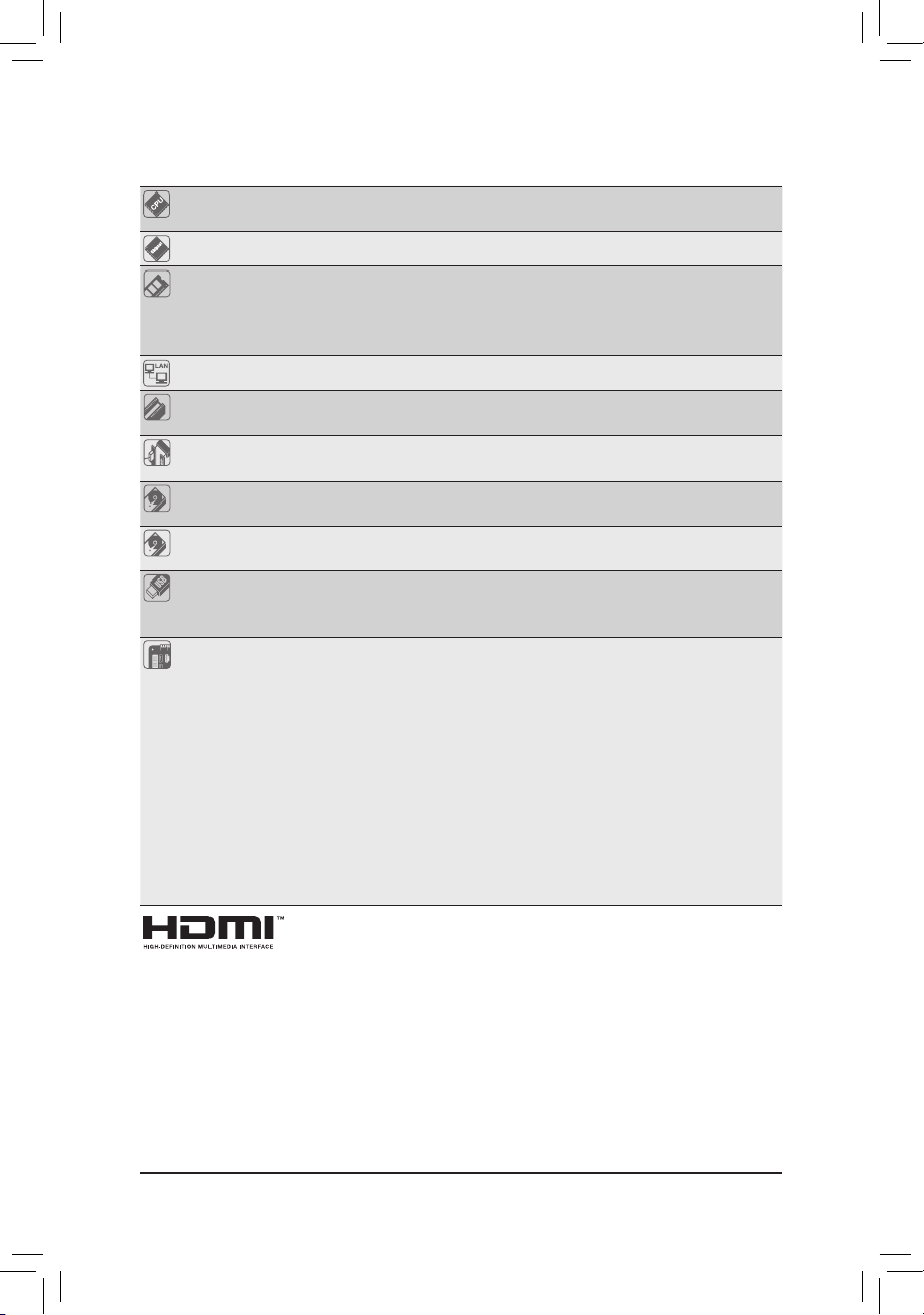
2-1 System Components
1
5
3
6
4
7
2
3
4
7
56
Item Decription
Power module
1.
2. Power supply board cage
3. Fan duct
4. GPU cooling fan
5. GPGPU card
6. System fans
7. Hard drive
- 14 -
Page 15
Hardware Installation
2-2 Replacing Power Supply Board Cage Cover
Before you remove or install the power supply board cage cover
• Make sure the system is not turned on or connected to AC power.
Follow these instructions to remove the power supply board cage cover:
1. Loosen and remove the screw securing the cover.
2. Holding the cage and vertically lift it from the system.
1
2
- 15 -
Page 16
Hardware Installation
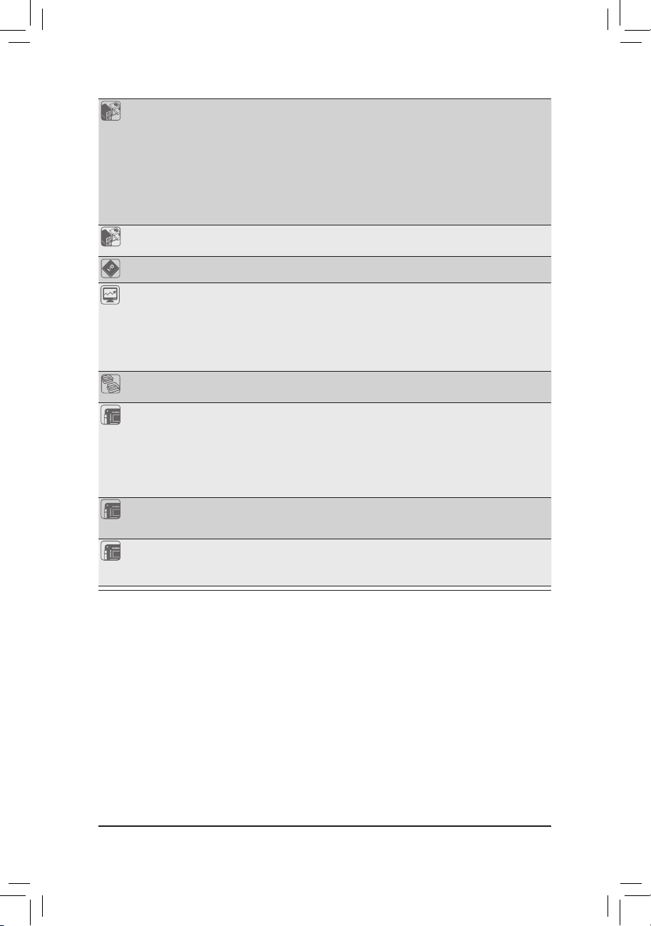
2-3 Replacing the Motherboard Tray
Follow these instructions to replace the motherboard tray:
1. Disconnect the power, SATA, front panel, and mainboard cable connectors.
2. Press the retaining clip on the left side of the tray along the direction of the arrow.
3. At the same time, pull out the tray by using its handle.Pull up the tray handle and slide of the
motherboard tray along the direction of the arrow.
1
2
3
- 16 -
Page 17
Hardware Installation
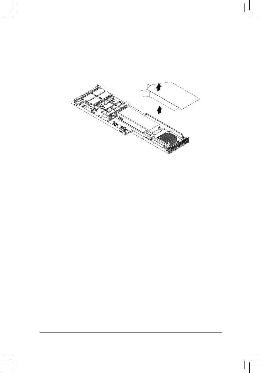
2-4 Removing and Installing the Fan Duct
Follow these instructions to remove/install the fan duct:
1. Lift up to remove the fan duct
2. To install the fan duct, align the fan duct with the guiding groove. Push down the fan duct into
chassis until its rmly seats.
- 17 -
Page 18
Hardware Installation
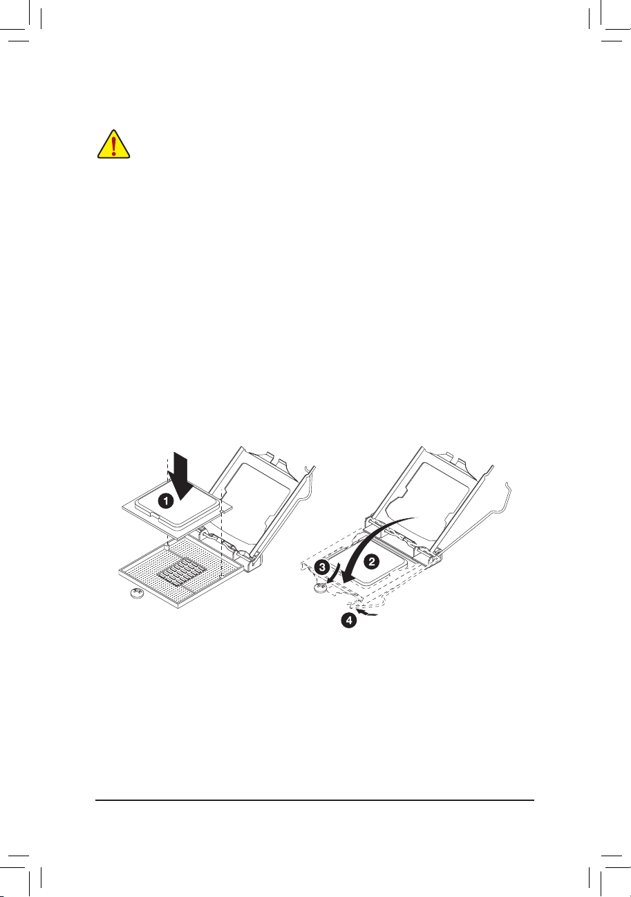
2-5 Installing the CPU
Read the following guidelines before you begin to install the CPU:
• Make sure that the motherboard supports the CPU.
• Always turn off the computer and unplug the power cord from the power outlet before installing
the CPU to prevent hardware damage.
• Unplug all cables from the power outlets.
• Disconnect all telecommunication cables from their ports.
• Place the system unit on a at and stable surface.
• Open the system according to the instructions.
WARNING!
Failure to properly turn off the server before you start installing componentsmay causeserious
damage. Do not attempt the procedures described in the following sections unless youare a
qualied servicetechnician.
Follow these instructions to install the CPU:
1. Raise the metal locking lever on the socket.
2. Remove the plastic covering on the CPU socket.Insert the CPU with the correct orientation. The
CPU only ts in one orientation.
3. Replace the metal cover.
4. Push the metal lever back into locked position.
- 18 -
Page 19

Hardware Installation
2-6 Installing the Heat Sink
Follow these instructions to install the heat sinks:
1. Apply thermal compound evenly on the top of the CPU.
2. Remove the protective cover from the underside of the heat sink.
3. Place the heat sink on top of the CPU and tighten the four positioning screws.
2
1
- 19 -
Page 20
Hardware Installation
2-7 Installing the Memory
Read the following guidelines before you begin to install the memory:
• Make sure that the motherboard supports the memory. It is recommended that memory of the
same capacity, brand, speed, and chips be used.
• Always turn off the computer and unplug the power cord from the power outlet before installing
the memory to prevent hardware damage.
• Memory modules have a foolproof design. A memory module can be installed in only one
direction. If you are unable to insert the memory, switch the direction.
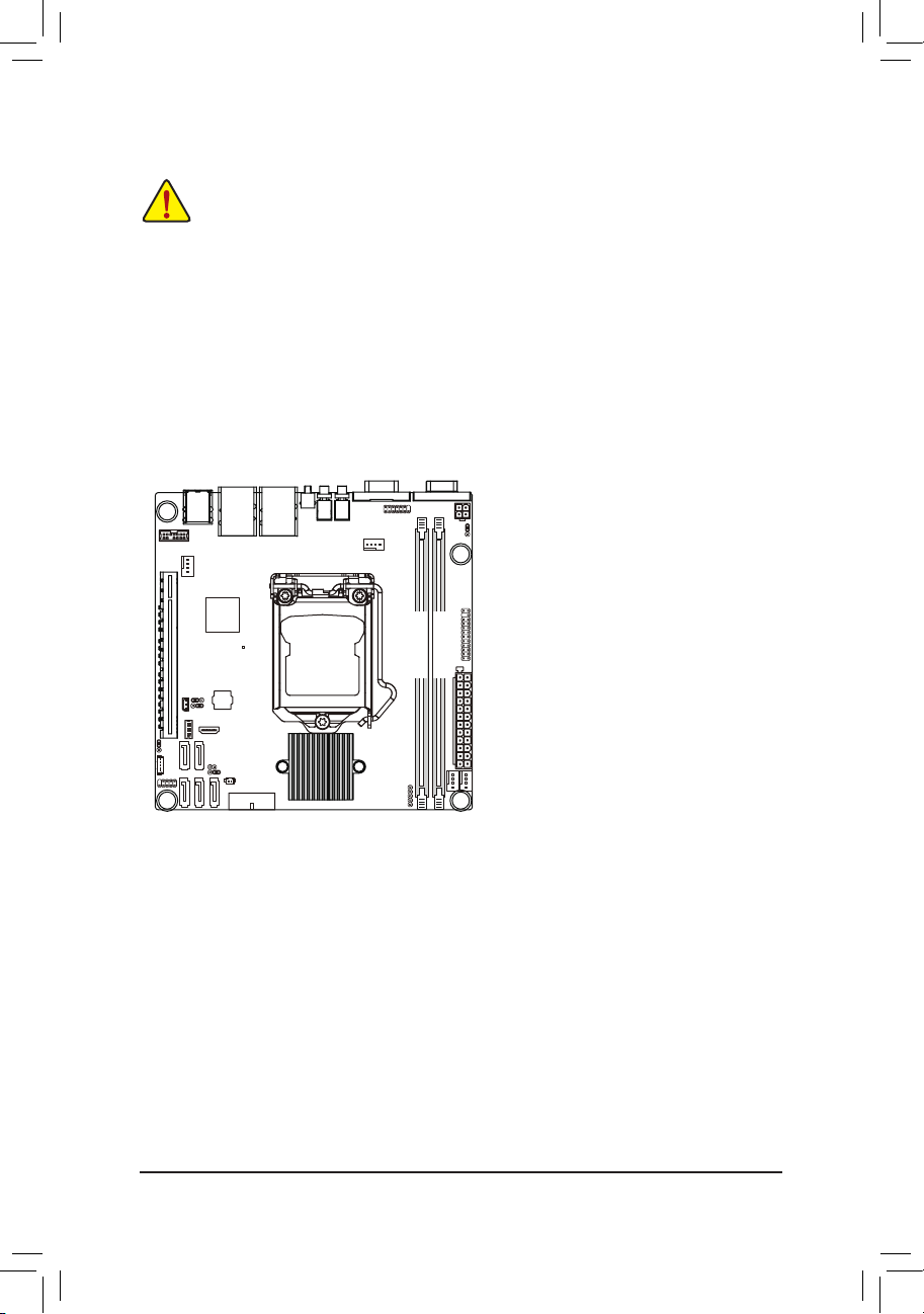
2-7-1 Dual Channel Memory Conguration
This motherboard provides two DDR3 memory sockets and supports Dual Channel Technology. When
the memory is installed, the BIOS will automatically detect the specications and capacity of the memory.
Enabling Dual Channel memory mode will double the original memory bandwidth.
DDR3_P0_B0
DDR3_P0_A0
Due to CPU limitations, read the following guidelines before installing the memory in Dual Channel mode.
1. Dual Channel mode cannot be enabled if only one DDR3 memory module is installed.
2. When enabling Dual Channel mode with two or four memory modules, it is recommended that
memory of the same capacity, brand, speed, and chips be used for optimum performance.
- 20 -
Page 21
Hardware Installation
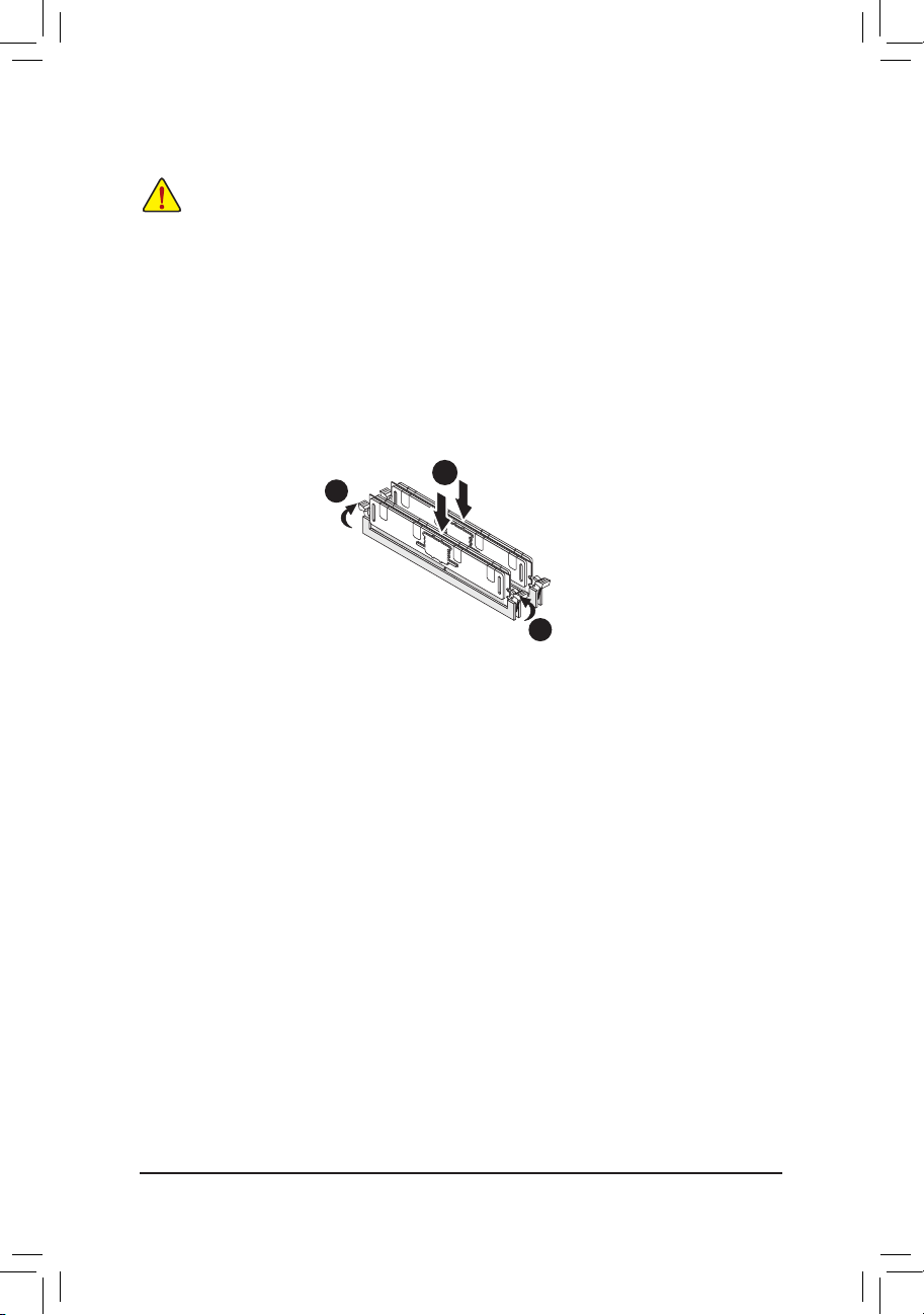
2-7-2 Installing a Memory
Before installing a memory module, make sure to turn off the computer and unplug the power
cord from the power outlet to prevent damage to the memory module.
Be sure to install DDR3 DIMMs on this motherboard.
Follow these instructions to install the Memory:
1. Insert the DIMM memory module vertically into the DIMM slot, and push it down.
2. Close the plastic clip at both edges of the DIMM slots to lock the DIMM module.
3. Reverse the installation steps when you wish to remove the DIMM module.
2
1
2
- 21 -
Page 22
Hardware Installation
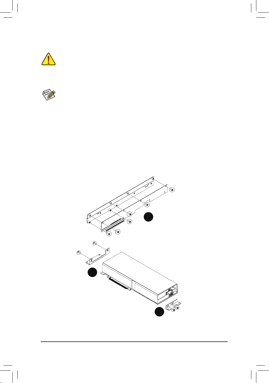
2-8 Installing the GPGPU Card
• Voltages can be present within the server whenever an AC power source is connected. This
voltage is present even when the main power switch is in the off position. Ensure that the
system is powered-down and all power sources have been disconnected from the server prior to
installing a GPGPU card.
Failure to observe these warnings could result in personal injury or damage to equipment.
• The riser assembly does not include a riser card or any cabling as standard. To install a GPGPU
card, a riser card must be installed.
Follow these instructions to GPGPU card:
1. Attach the mini card to the riser bracket and x the mini card with screws.
2. Attach the support bracket with two screws to the GPGPU card.
3. Insert the GPGPU card to the mini card slot
4. Orient the GPGPU card with the riser guide slot and push in the direction of the arrow until the
GPGPU card sits in the PCI card connector.
5. Fix the riser bracket with screws.
6. Fix the GPGPU card with the screws.
1
2
2
- 22 -
Page 23
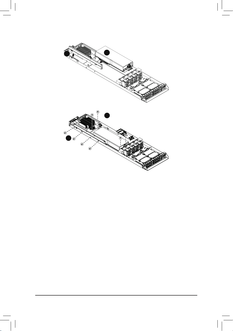
Hardware Installation
4
3
5
- 23 -
Page 24

Hardware Installation
2-9 Installing the Hard Disk Drive
Read the following guidelines before you begin to install the Hard disk drive:
• Take note of the drive tray orientation before sliding it out.
• The tray will not t back into the bay if inserted incorrectly.
• Make sure that the HDD is connected to the HDD connector on the backplane.
Follow these instructions to Hard disk drive:
1. Press the release button.
2. Pull the locking lever to remove the HDD tray.
3. Slide hard disk into blank.
4. Secure the hard drive to the tray with four (4) screws as shown. Do not over tighten thescrews.
Slide the blank into the bay until it locks into place.
5. Engage the HDD Security Lock. For detail instruction, please see the following section.
2
4
3
4
1
- 24 -
Page 25
Hardware Installation
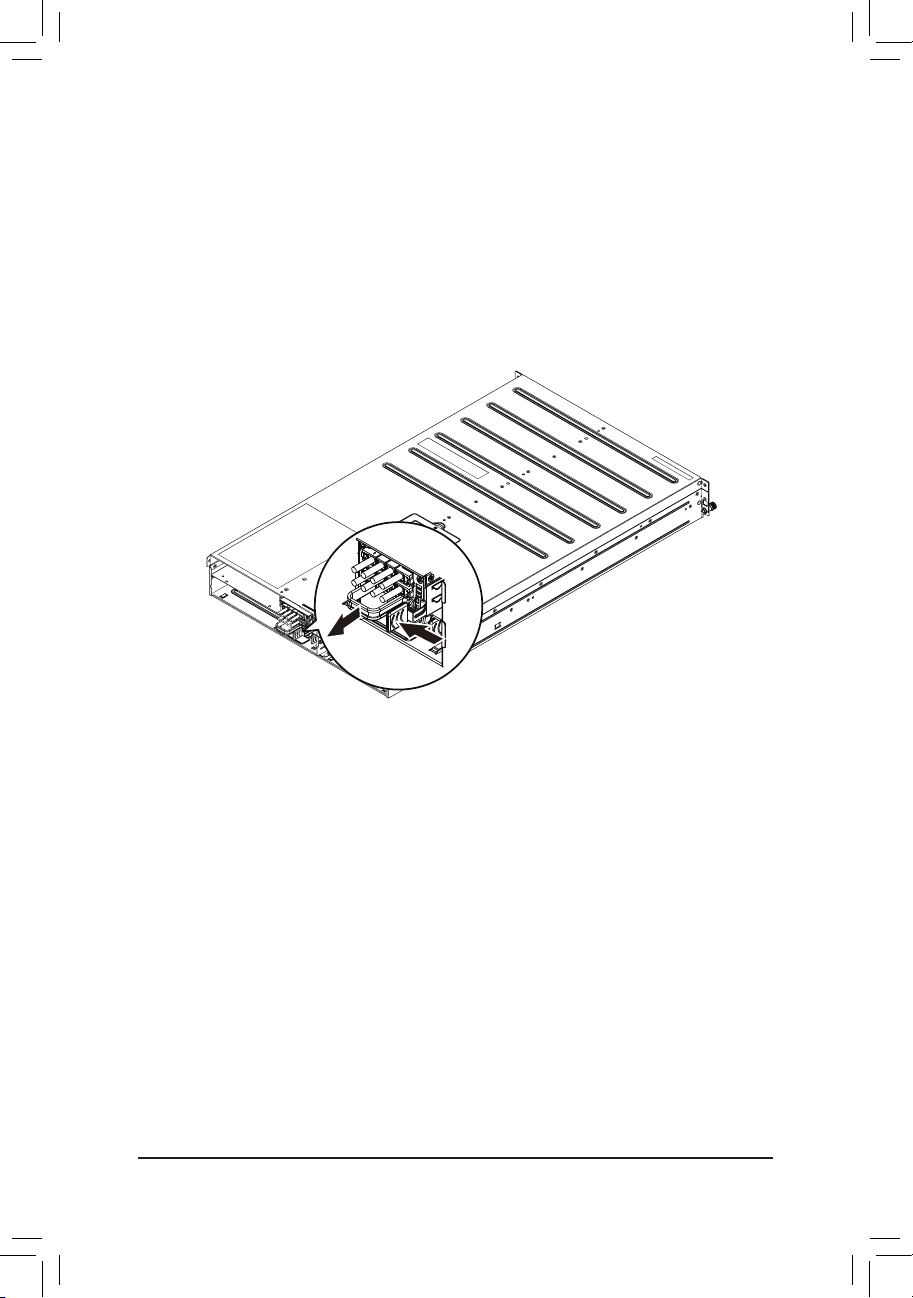
2-10 Replacing the Power Supply
Follow these instructions to replace the power supply:
1. Disconnect the three power cables.
2. Pull up the power supply handle.
3. Press the retaining clip on the right side of the power supply along the direction of the arrow.
4. At the same time, pull out the power supply by using its handle.
5. Insert the replacement power supply rmly into the chassis. Connect the AC power cord to the
replacement power supply.
- 25 -
Page 26
Hardware Installation
Chapter 3 System Appearance
3-1 Front View
3
4
21
3
4 21
5
1 23
4
No. Decription
ID button and LED
1
2. Power button and LED
3. VGA port
4. USB 3.0 ports
5. HDD bays
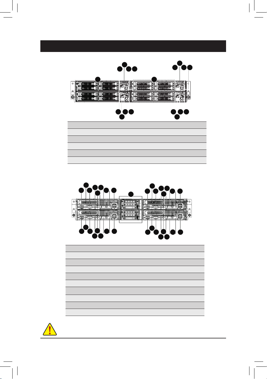
3-2 Rear View
2
6
4
1
3
7 8
5
2
5
1 3
7 8
4
6
No. Decription
VGA port
1
2. PCIe slot cover
3. Serial port
4. Power button and LED
5. ID Button and LED
6. Reset button (top)/NMI button (bottom)
7. LAN ports
8. USB 2.0 ports
9. Power module
NOTE! For detail LED description, please see the following section:
Front Panel LED and Buttons and Rear System LEDs and Button.
9
2
1
2
1 3
5
1 23
4
6
4
3
7 8
5
5
7 8
4
6
- 26 -
Page 27
Hardware Installation
3-3 HDD and Nodes Connection
1 3
42
- 27 -
Page 28
Hardware Installation
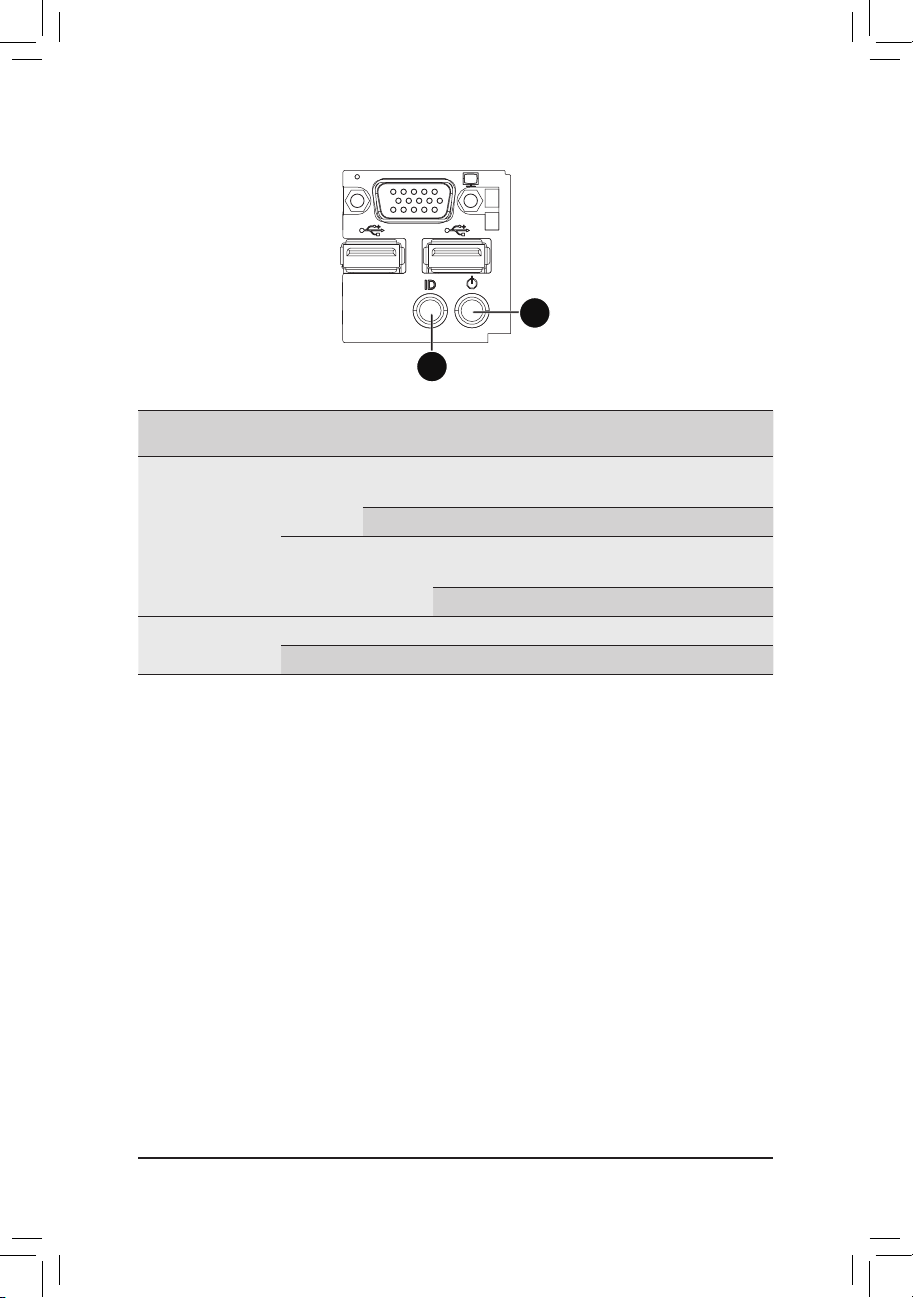
3-4 Front Panel LED and Buttons
2
1
No.
Name Color Status
Power button
and LED
1.
2. ID button
and LED
Critical
Event
Amber
Green On
Blue On N/A
N/A Off N/A
On No
Blink Yes
Description
System has power applied to it or ACPI
S0 state
System is in ACPI S5 state (Power off)
System has power applied to it or ACPI
No
S0 State
System is in ACPI S1 state (Entry S1)
No
Unit selected for identication.
No identication.
- 28 -
Page 29
Hardware Installation
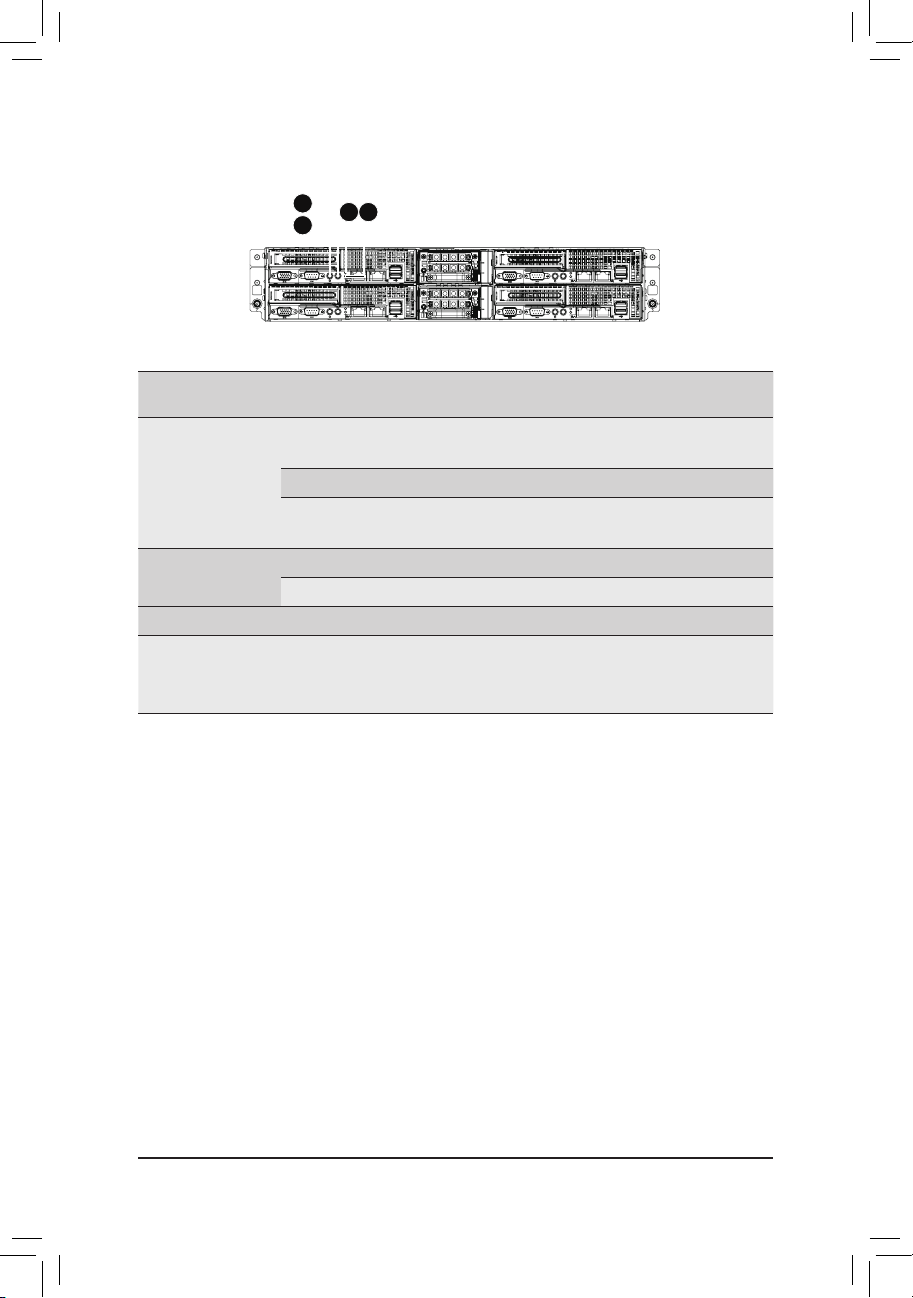
3-5 Rear System LEDs and Button
2
3
1
4
No.
1.
2.
3.
4.
Name Color Status
Green On N/A System has power applied to it or ACPI
Power button
and LED
Green Blink N/A System is in ACPI S1 state (sleep mode)
N/A Off N/A System is powered off.
ID button
and LED
Blue On N/A Unit selected for identication.
N/A Off N/A No identication.
Reset button
NMI button
Critical
Event
Description
S0 state
System is in ACPI S4 state (hlbernate mode)
Press this button to reset the system.
The NMI button allows a technician
servicing the server to generate a NMI to
the processor to help solve server errors.
- 29 -
Page 30
Hardware Installation
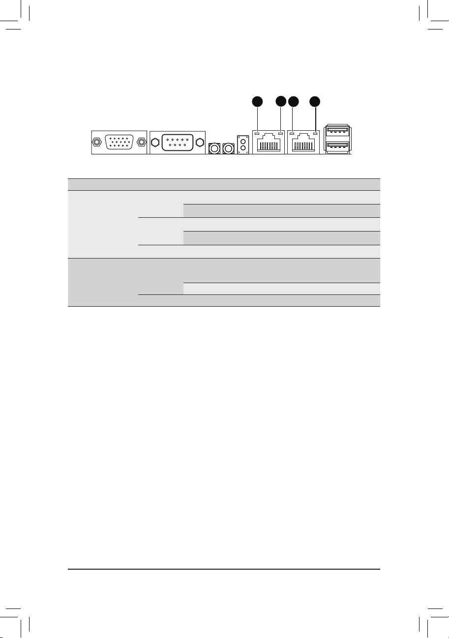
3-6 Rear System LAN LEDs
2
1 1
No. Name Color Status Description
On 1 Gbps data rate
Blink Identify 1 Gbps data rate
On 100 Mbps data rate
Blink Identify 100 Mbps data rate
On Link between system and
network or no access
Blink Data transmission or receiving is occurring
1
2.
Speed LED
Link/
Activity LED
Yel lo w
Green
N/A Off 10 Mbps data rate
Green
N/A Off No data transmission or receiving is occurring
2
- 30 -
Page 31

Hardware Installation
3-7 Hard Disk Drive LEDs
1
2
LED
No.
Mode Description
Hard disk drive is not present Off Off
Non-RAID
Onboard
RAID
1
SAS RAID
Card
2 Reserve Reserve Reserve Reserve
Hard disk drive is present but not active On Off
Hard disk drive is present and active Blink Off
Hard disk drive is not present Off Off
Hard disk drive is present but not active On Off
Hard disk drive is present and active Blink Off
Location On
RAID failed On On
Hard disk drive is rebuilding Blink Blink @ 1 Hz
Hard disk drive is not present Off Off
Hard disk drive is present but not active On Off
Hard disk drive is present and active Blink Off
Location On
RAID failed On On
Hard disk drive is rebuilding Blink Blink @ 1 Hz
Multi-Color LED
LED Active
Green
LED Active
Amber
Blink @ 4 Hz
(Alternative)
Blink @ 4 Hz
(Alternative)
- 31 -
Page 32

Hardware Installation
Chapter 4 Motherboard Components
4-1 GA-6LISL Motherboard Components
421 5 6
3
7
9
36
35
29
28
27
34
31
33
23
32
2526
30
24
22
8
12
13
10
11
14
15
16
1718192021
- 32 -
Page 33

Hardware Installation
Item Code Description
1 R_USB1 USB 2.0 ports
2 LAN2 LAN2 port
3 LAN1 L AN1 port
4 NMI_BMCRST Reset button (top)/NMI button (bottom)
5 ID_SW ID Switch button
6 PWR_SW Power button
7 COM1 Serial port
8 F P_VGA1 Front panel VGA header
9 VGA1 VGA port
10 P12V_ AUX1 4 pin power connector
11 CFG5
12 DDR3_P0_B0 DIMM slot
13 DDR3_P0_A0 DIMM slot
14 FP_1 Front panel header
15 ATX1 24 pin main power connector
16 SYS_ FAN2 System fan connector#2
17 SYS_FAN3 System fan connector#3
18 PWR_DET PMBus connector
19 CPU0 Intel LGA1150 socket
20 U 516 Intel C226 chipset
21 F_USB 3 USB 3.0 header
22 SATA_ DOM 4 SATA port 4 DOM support jumper
23 CASE_OPEN Case open intrusion header
24 HDMI* HDMI connector*
25 B AT Battery power cable connector
26 S ATA0~4 SATA 6Gb/s connectors
27 F_ USB2_1 USB 2.0 header
28 S ATA_SG PIO SATA SGPIO header
29 CLRCMOS Clear CMOS jumper
30 ME_UPDATE ME Update jumper
31 BIOSRCVR BIOS recovery jumper
32 BMC_LED1 BMC readiness LED
33 U546 ASPEED 2300 BMC chipset
34 IPMB1 IPMB connector
35 PCIE _1 PCI-E x16 slot
36 TPM TPM module connector
PCI-E x16 and x8 bandwid th sw itch
jumper
The HDMI connector is HDCP compliant and supports Dolby True HD and DTS HD
Master Audio formats. It also supports up to 192KHz/24bit 8-channel LPCM audio
output. You can use this port to connect your HDMI-supported monitor. The maximum supported resolution is
4096x2160@24Hz or 2560x1600@60Hz, but the actual resolutions supported are dependent on the monitor
being used.
- 33 -
Page 34

Hardware Installation
4-2 Jumper Setting
3
2
4
1
No. Jumper Code Jumper Setting
CAUTION!
If the SATA DOM power is supplied by the
motherboard, set the jumper to pin 1-2.
If the SATA DOM power is supplied by external
power, set the jumper to pin 2-3.
SATA _DO M4
1.
(SATA port 4 DOM Jumpers)
If a SATA type hard drive is connected to the motherboard,
please ensure the jumper is closed and set to 2-3 pins (Default
setting), in order to reduce any risk of hard disk damage.
5
ME_UPDATE
2.
(ME Recover Jumpers)
BIOSRCVR
3.
(BIOS Recovery Jumper)
CLR_CMOS
4.
(Clearing CMOS Jumper)
CFG5
(PCIE_1 bandwidth
5.
switch Jumper)
Pin No. Denition
1 P5V
2 SATA_DOM4
3 GND
1-2 Close: ME recovery mode.
2-3 Close: Normal operation (Default setting)
1-2 Close: Normal operation (Default setting)
2-3 Close: BIOS recovery mode.
1-2 Close: Normal operation (Default setting)
2-3 Close: Clear CMOS data
1-2 Close: PCIE_1 operates in x16 bandwidth. (Default setting)
2-3 Close: PCIE_1 operates in x8 bandwidth.
- 34 -
Page 35

BIOS Setup
Chapter 5 BIOS Setup
BIOS (Basic Input and Output System) records hardware parameters of the system in the EFI on the
motherboard. Its major functions include conducting the Power-On Self-Test (POST) during system startup,
saving system parameters and loading operating system, etc. BIOS includes a BIOS Setup program that
allows the user to modify basic system conguration settings or to activate certain system features. When the
power is turned off, the battery on the motherboard supplies the necessary power to the CMOS to keep the
conguration values in the CMOS.
To access the BIOS Setup program, press the <F2> key during the POST when the power is turned on.
• BIOS ashing is potentially risky, if you do not encounter problems of using the current BIOS
version, it is recommended that you don't ash the BIOS. To ash the BIOS, do it with caution.
Inadequate BIOS ashing may result in system malfunction.
• It is recommended that you not alter the default settings (unless you need to) to prevent system
instability or other unexpected results. Inadequately altering the settings may result in system's
failure to boot. If this occurs, try to clear the CMOS values and reset the board to default values.
(Refer to the Exit section in this chapter or introductions of the battery/clearing CMOS jumper in
Chapter 1 for how to clear the CMOS values.)
BIOS Setup Program Function Keys
<f><g> Move the selection bar to select the screen
<h><i> Move the selection bar to select an item
<+> Increase the numeric value or make changes
<-> Decrease the numeric value or make changes
<Enter> Execute command or enter the submenu
<Esc> Main Menu: Exit the BIOS Setup program
Submenus: Exit current submenu
<F1> Show descriptions of general help
<F3> Restore the previous BIOS settings for the current submenus
<F9> Load the Optimized BIOS default settings for the current submenus
<F10> Save all the changes and exit the BIOS Setup program
- 35 -
Page 36

BIOS Setup
Main
This setup page includes all the items in standard compatible BIOS.
Advanced
This setup page includes all the items of AMI BIOS special enhanced features.
(ex: Auto detect fan and temperature status, automatically congure hard disk parameters.)
Chipset
This setup page includes all the submenu options for conguring the function of North Bridge and South
Bridge.
(ex: Auto detect fan and temperature status, automatically congure hard disk parameters.)
Security
Change, set, or disable supervisor and user password. Conguration supervisor password allows you to
restrict access to the system and BIOS Setup.
A supervisor password allows you to make changes in BIOS Setup.
A user password only allows you to view the BIOS settings but not to make changes.
Server Management
Server additional features enabled/disabled setup menus.
Event Logs
This setup page provides items for conguration of Smbios Event Log settings and display the Smbios
event logs information.
Boot
This setup page provides items for conguration of boot sequence.
Exit
Save all the changes made in the BIOS Setup program to the CMOS and exit BIOS Setup. (Pressing
<F10> can also carry out this task.)
Abandon all changes and the previous settings remain in effect. Pressing <Y> to the confirmation
message will exit BIOS Setup. (Pressing <Esc> can also carry out this task.)
- 36 -
Page 37

BIOS Setup
5-1 The Main Menu
Once you enter the BIOS Setup program, the Main Menu (as shown below) appears on the screen. Use
arrow keys to move among the items and press <Enter> to accept or enter other sub-menu.
Main Menu Help
The on-screen description of a highlighted setup option is displayed on the bottom line of the Main Menu.
Submenu Help
While in a submenu, press <F1> to display a help screen (General Help) of function keys available for the
menu. Press <Esc> to exit the help screen. Help for each item is in the Item Help block on the right side of
the submenu.
• When the system is not stable as usual, select the Restore Defaults item to set your system to
its defaults.
• The BIOS Setup menus described in this chapter are for reference only and may differ by BIOS
version.
- 37 -
Page 38

BIOS Setup
BIOS Information
BIOS Version
Display version number of the BIOS setup utility.
BIOS Build Date and Time
Displays the date and time when the BIOS setup utility was created.
BMC Information
BMC Firmware Version
Display version number of the BMC setup utility.
SDR Version
Display the SDR version of the BMC setup utility.
FRU Version
Display the FRU version of the BMC setup utility.
Processor Information
Processor Information
CPU Type/Brand String/Frequency/Processor ID/Stepping/Number of Processors/
Microcode Revison
Displays the technical specications for the installed processor.
Memory Information
Memory Frequency
Display the frequency information of the installed memory.
System Date
Set the date following the weekday-month-day- year format.
System Time
Set the system time following the hour-minute- second format.
- 38 -
Page 39

BIOS Setup
5-2 Advanced Menu
The Advanced menu display submenu options for conguring the function of various hardware components.
Select a submenu item, then press Enter to access the related submenu screen.
- 39 -
Page 40

BIOS Setup
5-2-1 ACPI Conguration
ACPI Settings
ACPI Sleep State
Select the highest ACPI sleep state the system will enter, when the suspend button is pressed.
Options available: Suspend Disabled/S1 only (CPU Stop Clock) for OS to choose from.
Default setting is S1 only (CPU Stop Clock).
- 40 -
Page 41

BIOS Setup
5-2-2 Trusted Computing (Optional)
Conguration
Security Device Support
Select Enabled to activate TPM support feature.
Options available: Enabled/Disabled. Default setting is Disabled.
Current Status Information
Display current TPM status information.
- 41 -
Page 42

BIOS Setup
5-2-3 PCI Subsystem Settings
PCI Express Slot #1 I/O ROM
When enabled, This setting will initialize the device expansion ROM for the related PCI-E slot.
Options available: Enabled/Disabled. Default setting is Enabled.
Onboard LAN I/O ROM Option
Congure onboard LAN devices and initialize device expansion ROM.
Options available: PXE/iSCSI. Default setting is PXE.
Onboard LAN1/2 I/O ROM
Enable/Disable onboard LAN devices and initialize device expansion ROM.
Options available: Enabled/Disabled. Default setting is Enabled.
PCI 64bit Resources Handling
Above 4G Decoding
Enable/Disable Above 4G Decoding.
Options available: Enabled/Disabled. Default setting is Disabled.
PCI Common Settings
PCI Latency Timer
Value to be programmed into PCI Latency Timer Register.
Options available: 32 PCI Bus Clocks/64 PCI Bus Clocks/96 PCI Bus Clocks/128 PCI Bus Clocks/160
PCI Bus Clocks/192 PCI Bus Clocks/224 PCI Bus Clocks/248 PCI Bus Clocks/.
Default setting is 32 PCI Bus Clocks.
- 42 -
Page 43

BIOS Setup
VGA Palette Snoop
Enable/Disable VGA Palette Tegisters Snooping.
Options available: Enabled/Disabled. Default setting is Disabled.
PERR Generation
When this item is set to enabled, PCI bus parity error (PERR) is generated and is routed to NMI.
Options available: Enabled/Disabled. Default setting is Disabled.
SERR Generation
When this item is set to enabled, PCI bus system error (SERR) is generated and is routed to NMI.
Options available: Enabled/Disabled. Default setting is Disabled.
PCI Express Settings
Press [Enter] for conguration of advanced items.
- 43 -
Page 44

BIOS Setup
5-2-3-1 PCI Express Settings
PCI Express Device Register Settings
Relaxed Ordering
Enable/DIsable PCI Express Device Relaxed Ordering feature.
Options available: Enabled/Disabled. Default setting is Disabled.
Extended Tag
Wnen this feature is enabled, the system will allow device to use 8-bit Tag eld as a requester.
Options available: Enabled/Disabled. Default setting is Disabled.
No Snoop
Enable/Disable PCI Express Device No Snoop option.
Options available: Enabled/Disabled. Default setting is Enabled.
Maximum Playload
Set maximum playload for PCI Express Device or allow system BIOS to select the value.
Options available: Auto/128 Bytes/256 Bytes/512 Bytes/1024 Bytes/2048 Bytes/4096 Bytes.
Default setting is Auto.
Maximum Read Request
Set maximum Read Reuest size for PCI Express Device or allow system BIOS to select the value.
Options available: Auto/128 Bytes/256 Bytes/512 Bytes/1024 Bytes/2048 Bytes/4096 Bytes.
Default setting is Auto.
Extended Synch
Wnen this feature is enabled, the system will allow generation of Extended Synchronization patterns.
Options available: Enabled/Disabled. Default setting is Disabled.
- 44 -
Page 45

BIOS Setup
Link Training Retry
Dene the number of Retry Attempts software wil take to retrain the link if previous training attempt was
unsuccessful. Press <+> / <-> keys to increase or decrease the desired values.
Link Training Timeout (us)
Dene the number of Microseconds software will wait before polling 'Link Training' bit in Link Status
register. Press <+> / <-> keys to increase or decrease the desired values. Value rang is from 10 to
10000 us.
Unpopulated Links
When this item is set to 'Disable Link, the system will operate power save feature for those unpopulated
PCI Express links.
Options available: Keep Link ON/ Disable Link. Default setting is Keep Link ON.
Restore PCIE Registers
When this item is enabled, the system will restore PCI Express device conguration on S3 resume.
Warning: Enabling this may cause issues with other hardware after S3 resume.
Options available: Enabled/Disabled. Default setting is Disabled.
- 45 -
Page 46

BIOS Setup
5-2-4 CPU Conguration
- 46 -
Page 47

BIOS Setup
CPU Conguration
CPU Type/Signature/Processor Family/Microcode Patch/FSB Speed/Max CPU Speed/
Min CPU Speed/ Processor Cores/Intel HT Technology/Intel VT-x Technology/
Intel SMX Technology
Displays the technical specications for the installed processor.
64-bit
Display the supported information of installed CPU.
EIST Technology
Display Intel EIST Technology function support information.
CPU C3 state
Display the support information of CPU C3 state feature.
CPU C6 state
Display the support information of CPU C6 state feature.
CPU C7 state
Display the support information of CPU C7 state feature.
Cache Information
L1 Data Cache / L1 Code Cache / L2 Cache / L3 Cache
Displays the technical specications for the installed processor.
Hyper-threading
The Intel Hyper Threading Technology allows a single processor to execute two or more separate
threads concurrently. When hyper-threading is enabled, multi-threaded software applications can
execute their threads, thereby improving performance.
Options available: Enabled/Disabled. Default setting is Enabled.
- 47 -
Page 48

BIOS Setup
Active Processor Cores
Allows you to determine whether to enable all CPU cores.
Options available: All/1/2/3. Default setting is All.
(Note)
Overclocking lock
Enable/Disable Overclocking lock.
Options available: Enabled/Disabled. Default setting is Disabled.
Limit CPUID Maximum
When enabled, the processor will limit the maximum COUID input values to 03h when queried, even if
the processor suppports a higher CPUID input value.
When disabled, the processor will return the actual maximum CPUID input value of the processor when
queried.
Options available: Enabled/Disabled. Default setting is Disabled.
Execute Disable Bit
When enabled, the processor prevents the execution of code in data-only memory pages. This provides
some protection against buffer overow attacks.
When disabled, the processor will not restrict code execution in any memory area. This makes the
processor more vulnerable to buffer overow attacks.
Options available: Enabled/Disabled. Default setting is Enabled.
Intel Virtualization Technology
Select whether to enable the Intel Virtualization Technology function. VT allows a single platform to run
multiple operating systems in independent partitions.
Options available: Enabled/Disabled. Default setting is Enabled.
Hardware Prefetcher
Select whether to enable the speculative prefetch unit of the processor.
Options available: Enabled/Disabled. Default setting is Enabled.
Adjacent Cache Line Prefetch
When enabled, cache lines are fetched in pairs. When disabled, only the required cache line is fetched.
Options available: Enabled/Disabled. Default setting is Enabled.
CPU AES
Enable/Disable CPU Advanced Encryption Standard instructions.
Options available: Enabled/Disabled. Default setting is Enabled.
Boot performance mode
Congure the Boot performance mode.
Options available: Turbo Performance/Max Non-Turbo Performance/Max bettery/Turbo Performance.
Default setting is Turbo Performance.
EIST (Enhanced Intel SpeedStep Technology)
Conventional Intel SpeedStep Technology switches both voltage and frequency in tandem between high
and low levels in response to processor load.
Options available: Enabled/Disabled. Default setting is Enabled.
(Note) This item is present only if you install a CPU that supports this feature. For more information about
Intel CPUs' unique features, please visit Intel's website.
- 48 -
Page 49

BIOS Setup
Turbo Mode
When this item is enabled, tje processor will automatically ramp up the clock speed of 1-2 of its
processing cores to improve its performance.
When this item is disabled, the processor will not overclock any of its core.
Options available: Enabled/Disabled. Default setting is Enabled.
Energy Performance
Energy Performance Bias is Intel CPU function.
The larger value in MSR_ENERGY_PERFORMANCE_BIAS register,
CPU will save more power but lose more performance.
Note: This register will be changed by OS too if OS support it like Windows 2008 or newer Linux.
Options available:
Performance : Write value 0 into MSR_ENERGY_PERFORMANCE_BIAS
Balanced Performance: Write value 7 into MSR_ENERGY_PERFORMANCE_BIAS
Balanced Energy: Write value 11 into MSR_ENERGY_PERFORMANCE_BIAS
Energy Efcient: Write value 15 into MSR_ENERGY_PERFORMANCE_BIAS
Default setting is Performance.
Platform power limit lock
Options available: Enabled/Disabled. Default setting is Enabled.
CPU C State
Enable/Disable CPU C State feature.
Options available: Enabled/Disabled. Default setting is Enabled.
Enhanced C1 state
Enable/Disable C1E State feature.
Options available: Enabled/Disabled. Default setting is Enabled.
CPU C3/C6 Report
Allows you to determine whether to let the CPU enter C3/C6 mode in system halt state. When enabled,
the CPU core frequency and voltage will be reduced during system halt state to decrease power
consumption. The C3/C6 state is a more enhanced power-saving state than C1.
Options available: Enabled/Disabled. Default setting is Enabled.
CPU C7 Report
Allows you to enable or disable the CPU C7 (ACPI C3) report.
Options available: Disabled/CPU C7/CPU C7s. Default setting is CPU C7s.
(Note)
(Note)
Package C state demotion
Congure state for the C-State package demotion.
Options available: Enabled/Disabled. Default setting is Disabled.
Package C state undemotion
Congure state for the C-State package undemotion.
Options available: Enabled/Disabled. Default setting is Disabled.
CFG lock
Options available: Enabled/Disabled. Default setting is Enabled.
- 49 -
Page 50

BIOS Setup
Package C State Limit
Congure state for the C-State package limit.
Options available: C0/C1/C3/C6/C7/C7s/C8/C9/C10/Auto. Default setting is Auto.
Intel TXT (LT) Support
Enable/Disable Intel TXT (LT) support.
Options available: Enabled/Disabled. Default setting is Disabled.
ACPI T State
Enable/Disable ACPI T state support.
Options available: Enabled/Disabled. Default setting is Disabled.
CPU DTS
Enable/Disable CPU DTS support.
Options available: Enabled/Disabled. Default setting is Disabled.
(Note) This item is present only if you install a CPU that supports this feature. For more information about
Intel CPUs' unique features, please visit Intel's website.
- 50 -
Page 51

BIOS Setup
5-2-5 SATA Conguration
- 51 -
Page 52

BIOS Setup
SATA Controller(s)
Enable/Disable the SATA controller.
Options available: Enabled/Disabled. Default setting is Enabled.
SATA Mode Selection
Select the on chip SATA type.
IDE Mode: When set to IDE, the SATA controller disables its RAID and AHCI functions and runs in the
IDE emulation mode. This is not allowed to access RAID setup utility.
RAID Mode: When set to RAID, the SATA controllerenables both its RAID and AHCI functions. You will
be allows access the RAID setup utility at boot time.
ACHI Mode: When set to AHCI,the SATA controller enables its AHCI functionality. Then the RAID
function is disabled and cannot be access the RAID setup utility at boot time.
Options available: IDE/RAID/ACHI/Disabled. Default setting is ACHI Mode.
SATA Test Mode
Enable/Disable SATA Test Mode.
Options available: Enabled/Disabled. Default setting is Disabled.
Aggressive LPM Support
Enable PCH to aggressively enter link power state.
Options available: Enabled/Disabled. Default setting is Enabled.
SATA Controller Speed
Indicates the maximum speed that the SATA controller can support.
Options available: Default/Gen1/Gen2/Gen3. Default setting is Default.
Software Feature Mask Conguration
Press [Enter] for conguration of advanced items.
Serial Port 0/1/2/3/4/5
The category identies Serial ATA type of hard disk that are installed in the computer.
System will automatically detect HDD type.
Port 0/1/2/3/4/5
Enable/Disable Port 0/1/2/3/4/5.
Options available: Enabled/Disabled. Default setting is Enabled.
Hot Plug (for Serial SATA Port 0/1/2/3/4/5)
Enable/Disable Hot Plug support for Serial ATA Port 0/1/2/3/4/5.
Options available: Enabled/Disabled. Default setting is Disabled.
External SATA (for Serial SATA Port 0/1/2/3/4/5)
Enable/Disable External SATA support for Serial ATA Port 0/1/2/3/4/5.
Options available: Enabled/Disabled. Default setting is Disabled.
SATA Device Type (for Serial SATA Port 0/1)
Dene the SATA Device for Serial ATA Port 0/1.
Options available: Hard Disk Drive/Solid State Drive. Default setting is Disabled.
Spin Up Device (for Serial SATA Port 0/1/2/3/4/5)
On an edge detect from 0 to 1, the PCH starts a COMreset initialization to the device.
Options available: Enabled/Disabled. Default setting is Disabled.
- 52 -
Page 53

BIOS Setup
5-2-5-1 Software Feature Mask Conguration
RAID 0
Enable/Disable RAID 0 feature.
Options available: Enabled/Disabled. Default setting is Enabled.
RAID 1
Enable/Disable RAID 1 feature.
Options available: Enabled/Disabled. Default setting is Enabled.
RAID 10
Enable/Disable RAID 10 feature.
Options available: Enabled/Disabled. Default setting is Enabled.
RAID 5
Enable/Disable RAID 5 feature.
Options available: Enabled/Disabled. Default setting is Enabled.
Intel Rapid Recovery Technology
Enable/Disable the Intel Rapid Start Technology (IRSTe) funciton. The IRSTe enables your system to get
up and running faster from even the deepest sleep, saving time and power consumption.
Options available: Enabled/Disabled. Default setting is Enabled.
OROM UI and BANNER
Enable/Disable OROM UI and BANNER feature.
Options available: Enabled/Disabled. Default setting is Enabled.
HDD Unlock
When this item is enabled, the HDD password unlock in the OS is enabled.
Options available: Enabled/Disabled. Default setting is Enabled.
- 53 -
Page 54

BIOS Setup
LED Locate
When this item is enabled, the LED/SGPIO hardware is attached and ping to locate feature is enabled
on the OS.
Options available: Enabled/Disabled. Default setting is Enabled.
IRRT Only on eSATA
When this item is enabled, only IRRT volumes can span internal and eSATA drives. If disabled, then any
RAID volue can span internal and eSATA drives
Options available: Enabled/Disabled. Default setting is Enabled.
Smart Response Technlogy
Enable/Disable Intel Smart Response Technlogy.
Options available: Enabled/Disabled. Default setting is Enabled.
OROM UI Delay
Options available: 2 Seconds/4 Seconds/6 Seconds/8 Seconds. Default setting is 2 Seconds.
- 54 -
Page 55

BIOS Setup
5-2-6 Info Report Conguration
Info Report Conguration
Post Report
Enable/Disable Post Report support.
Options available: Enabled/Disabled. Default setting is Enabled.
Delay Time
Options available: 0/1/2/3/4/5/6/78/9/10/Util Press ESC. Default setting isUntil Press ESC.
Error Message Report
Info Error Message
Enable/Disable Info Error Message support.
Options available: Enabled/Disabled. Default setting is Enabled.
Summary Screen
Summary Screen
Enable/Disable Summary Screen support.
Options available: Enabled/Disabled. Default setting is Disabled.
- 55 -
Page 56

BIOS Setup
5-2-7 USB Conguration
Legacy USB Support
Enables or disables support for legacy USB devices.
Options available: Auto/Enabled/Disabled. Default setting is Enabled.
XHCI Hand-off
Enable/Disable XHCI (USB 3.0) Hand-off support.
Options available: Enabled/Disabled. Default setting is Enabled.
EHCI Hand-off
Enable/Disable EHCI (USB 2.0) Hand-off function.
Options available: Enabled/Disabled. Default setting is Disabled.
USB Mass Storage Driver Support
Enable/Disable USB Mass Storage Driver Support.
Options available: Enabled/Disabled. Default setting is Enabled.
Port 60/64 Emulation
Enable I/O port 60h/64h emulation support. This should be enabled for the complete USB Keyboard
Legacy support for non-USB aware OS.
Options available: Enabled/Disabled. Default setting is Enabled.
(Note)
(Note) This item is present only if you attach USB types of device.
- 56 -
Page 57

BIOS Setup
5-2-8 Super IO Conguration
- 57 -
Page 58

BIOS Setup
Super IO Chip
Display the model name of Super IO chip.
Serial Port 0 Conguration
Serial Port 0
When enabled allows you to congure the serial port settings. When set to Disabled, displays no
conguration for the serial port.
Options available: Enabled/Disabled. Default setting is Enabled.
Device Settings
Display the Serial Port 0 base I/O addressand IRQ.
Change Settings
Change Serial Port 0 device settings. When set to Auto allows the server’s BIOS or OS to select a
conguration.
Options available: Auto/IO=3F8; IRQ=4/IO=3F8h; IRQ=3,4,5,6,7,10,11,12/
IO=2F8h; IRQ=3,4,5,6,7,10,11,12 /IO=3E8h; IRQ=3,4,5,6,7,10,11,12/IO=2E8h; IRQ=3,4,5,6,7,10,11,12.
Default setting is Auto.
- 58 -
Page 59

BIOS Setup
5-2-9 Serial Port Console Redirection
- 59 -
Page 60

BIOS Setup
COM1/Serial Port for Out-of Band Management/Windows Emergency
Management Service (EMS)
Console Redirection
Select whether to enable console redirection for specied device. Console redirection enables users to
manage the system from a remote location.
Options available: Enabled/Disabled. Default setting is Disabled.
(Note)
Console Redirection Settings
Terminal Type
Select a terminal type to be used for console redirection.
Options available: VT100/VT100+/ANSI /VT-UTF8.
Bits per second
Select the baud rate for console redirection.
Options available: 9600/19200/57600/115200.
Data Bits
Select the data bits for console redirection.
Options available: 7/8.
Parity
A parity bit can be sent with the data bits to detect some transmission errors.
Even: parity bi is 0 if the num of 1's in the data bits is even.
Odd: parity bit is0if num of 1's the data bits is odd.
Mark: parity bit is always 1. Space: Parity bit is always 0.
(Note) Advanced items prompt when this item is dened.
- 60 -
Page 61

BIOS Setup
Mark and Space Parity do not allow for error detection.
Options available: None/Even/Odd/Mark/Space.
Stop Bits
Stop bits indicate the end of a serial data packet. (A start bit indicates the beginning). The standard
setting is 1 stop bit. Communication with slow devices may require more than 1 stop bit.
Options available: 1/2.
Flow Control
Flow control can prevent data loss from buffer overow. When sending data, if the receiving buffers are
full, a 'stop' signal can be sent to stop the data ow. Once the buffers are empty, a 'start' signal can be
sent to re-start the ow. Hardware ow control uses two wires to send start/stop signals.
Options available: None/Hardware RTS/CTS.
VT-UTF8 Combo Key Support
(Note)
Enable/Disable VT-UTF8 Combo Key Support.
Options available: Enabled/Disabled. Default setting is Enabled.
Recorder Mode
(Note)
When this mode enabled, only text will be send. This is to capture Terminal data.
Options available: Enabled/Disabled.
Resolution 100x31
(Note)
Enables or disables extended terminal resolution.
Options available: Enabled/Disabled.
Legacy OS Redirection Resolution
(Note)
On Legacy OS, the number of Rows and Columns supported redirection.
Options available: 80x24/80X25.
Putty KeyPad
(Note)
Select function FunctionKey and KeyPad on Putty.
Options available: VT100/LINUX/XTERMR6/SCO/ESCN/VT400.
Redirection After BIOS POST
(Note)
This option allows user to enable console redirection after O.S has loaded.
Options available: Always Enable/Boot Loader. Default setting is Always Enable.
Out-of-Bnad Mgmt Port
Microsoft Windows Emerency Management Service (EMS) allows for remote management of a Windows
Server OS through a serial port.
Options available: COM1/COM2.
SOL Switch
When enabled, COM1 Switch to AST2300 SOL UART.
When disabled, COM1 Switch to IT8728 SOL UART.
Options available: Enabled/Disabled. Default setting is Disabled.
(Note) Advanced items prompt when this item is dened.
- 61 -
Page 62

BIOS Setup
5-2-10 Network Stack
Network stack
Enable/Disable UEFI network stack.
Options available: Enabled/DIsabled. Default setting is Disabled.
Ipv4 PXE Support
Enable/Disable Ipv4 PXE feature.
Options available: Enabled/DIsabled. Default setting is Enabled.
Ipv6 PXE Support
Enable/Disable Ipv6 PXE feature.
Options available: Enabled/DIsabled. Default setting is Enabled.
(Note)
(Note)
(Note) This item appears when Network Stack is set to Enabled.
- 62 -
Page 63

BIOS Setup
5-2-11 iSCSI Conguration
iSCSI Initiator Name
Add an Attempts
Press [Enter] for conguration of advanced items.
Delete Attempts
Press [Enter] for conguration of advanced items.
Change Attempt Order
Press [Enter] for conguration of advanced items.
- 63 -
Page 64

BIOS Setup
5-2-12 Intel (R) I210 Gigabit Network Connection
- 64 -
Page 65

BIOS Setup
PORT CONFIGURATION MENU
NIC Conguration
Press [Enter] for conguration of advanced items.
Blink LEDs (range 0-15 seconds)
Blink LEDs for the specied duration (up to 15 seconds).
Press the numberic keys to input the desired value.
PORT CONFIGURATION INFORMATION
UEFI Driver
Display the UEFI driver information.
Adapter PBA
Display the Adapter PBA information.
Chip Type
Display the Chip type.
PCI Device ID
Display the PCI device ID.
Bus:Device:Function
Display the number of Bus/Device/Function
Link Status
Display the link status.
MAC Address
Display the Factory MAC address information.
Virtual MAC Address
Display the virtual MAC address information.
Link Speed
Change link speed duplex for current port.
Options available: Auto Negotiated/10Mbps Half/10Mbps Half/10Mbps Half/100Mbps Full.
Default setting is Auto Neg0tiated.
Wake On LAN
Enable/Disable Wake On LAN feature.
Options available: Enabled/DIsabled. Default setting is Enabled.
- 65 -
Page 66

BIOS Setup
5-3 Chipset Menu
The Chipset menu display submenu options for conguring the function of North Bridge and South Bridge.
Select a submenu item, then press Enter to access the related submenu screen.
- 66 -
Page 67

BIOS Setup
5-3-1 System Agent (SA)Conguration
System Agent Bridge Name
Display the System Agent (SA) Bridge Name.
System Agent RC Version
Display the version number of System Agent RC.
VT-d Capability
Display the VT-d support information.
VT-d
Enable/Disable Intel Virtualization Technology for Directed I/O (VT-d) feature.
Options available: Enabled/DIsabled. Default setting is Enabled.
Options available: Enabled/DIsabled. Default setting is Enabled.
Enable NB CRID
Options available: Enabled/DIsabled. Default setting is Disabled.
Graphics Conguration
Press [Enter] for conguration of advanced items.
NB PCIe Conguration
Press [Enter] for conguration of advanced items.
Memory Conguration
Press [Enter] for conguration of advanced items.
- 67 -
Page 68

BIOS Setup
5-3-1-1 Graphic Conguration
Graphic Conguration
Primary Display Device
Congure the Primary display device.
Options available: Auto/IGFX(if the CPU support graphic)/PEG/Onboard VGA. Default setting is Auto.
- 68 -
Page 69

BIOS Setup
5-3-1-2 NB PCIe Conguration
NB PCIe Conguration
PEG0
Display PEG0 conguration information.
PEG0 - Gen X
Congure PEG0 B0:D1:F0 Gen1-Gen3.
Options available: Auto/Gen1/Gen2/Gen3. Default setting is Auto.
PEG1
Display PEG1 conguration information.
PEG1 - Gen X
Congure PEG1 B0:D1:F1 Gen1-Gen3.
Options available: Auto/Gen1/Gen2/Gen3. Default setting is Auto.
PEG2
Display PEG2 conguration information.
PEG2 - Gen X
Congure PEG2 B0:D1:F2 Gen1-Gen3.
Options available: Auto/Gen1/Gen2/Gen3. Default setting is Auto.
Run-time C7 Allowed
Congure Run-time C7 feature.
Options available: Enabled/Disabled. Default setting is Enabled.
Enable PEG
Enable/Disable PEG.
Options available: Enabled/Disabled. Default setting is Auto.
- 69 -
Page 70

BIOS Setup
Detect Non-Compliance Device
Detect Non-Compliance PCI Express Device in PEG.
Options available: Enabled/Disabled. Default setting is Disabled.
Program PCIe ASPM after OpROM
Enable/Disable Program PCIe ASPM after OpROM.
Options available: Enabled/Disabled. Default setting is Disabled.
PEG0 De-emphasis Control
PEG0:Congure the De-emphasis control on PEG.
Options available: Options available: -6 dB/-3.5 dB. Default setting is -3.5 dB.
PEG1 De-emphasis Control
PEG1:Congure the De-emphasis control on PEG.
Options available: Options available: -6 dB/-3.5 dB. Default setting is -3.5 dB.
PEG2 De-emphasis Control
PEG2:Congure the De-emphasis control on PEG.
Options available: Options available: -6 dB/-3.5 dB. Default setting is -3.5 dB.
PEG0 - ASPM
Control ASPM support for the PEG Device. This has no effect if PEG is not the currently active device.
Options available: Enabled/Disabled. Default setting is Disabled.
PEG1 - ASPM
Control ASPM support for the PEG Device. This has no effect if PEG is not the currently active device.
Options available: Enabled/Disabled. Default setting is Disabled.
PEG2 - ASPM
Control ASPM support for the PEG Device. This has no effect if PEG is not the currently active device.
Options available: Enabled/Disabled. Default setting is Disabled.
PEG Sampler Calibrate
Enable or disable PEG Sampler Calibrate\nAuto means Disabled for SNB MB/DT, Enabled for IVB A0
B0.
Options available: Enabled/Disabled. Default setting is Disabled.
Swing Control
Perform PEG Swing Control, on IVB C0 and Later.
Options available: Reduced/Half/Full. Default setting is Full.
PEG Gen3 Equalization
Perform PEG Gen3 Equalization steps.
Options available: Enabled/Disabled. Default setting is Enabled.
Gen3 Eq Preset Search
Perform PEG Gen3 Preset Search algorithm, on IVB C0 and Later.
Options available: Enabled/Disabled. Default setting is Enabled.
PEG RxCEM LoopBack Mode
Options available: Enabled/Disabled. Default setting is Disabled.
- 70 -
Page 71

BIOS Setup
5-3-1-3 Memory Conguration
Memory Information
Memory RC Version
Display version number of installed memeory.
Memory Frequency
Display the frequency information of installed memory.
Total Memory
Determines how much total memory is present during the POST.
Memory Voltage
Display the voltage information of installed memory.
DIMM Information:
DDR3_P0_A0/DDR3_P0_A1/DDR3_P0_B0/DDR3_P0_B1 Status
The size of memory installed on each of the DDR3 slots.
CAS Latency (tCL)
Display the CAS Latency (tCL) information of installed memory.
Minimum delay time
CAS to RAS (tRCDmin)
Display the CAS to RAS (tRCDmin) information of installed memory.
Row Precharge (tRPimin)
Display the Row Precharge (tRPimin) information of installed memory.
Active to Precharge (tRCDmin)
Display the Active to Precharge (tRCDmin) information of installed memory.
- 71 -
Page 72

BIOS Setup
Memory Frequency Limiter
Maximum Memory Frequency Selections in Mhz.
Options available: Auto/1067/1333/1600/1867/2133/2400/2667. Default setting is Auto.
Max TOLUD
Maximum Value of TOLUD. Dynamic assignment would adjust TOLUD automatically based on largest
MMIO length of installed graphic controller.
Options available: Dynamic/3.5 GB/3.25 GB/3 GB/2.75 GB/2.5 GB/2.25 GB/2 GB/1.75 GB/1.5 GB/
1.25 GB/1 GB. Default setting is Dynamic.
- 72 -
Page 73

BIOS Setup
5-3-2 PCH-IO Conguration
Intel PCH RC Version/Intel PCH SKU/Intel PCH Rev ID Information
Displays the RC version, SKU and Reverison ID information of PCH.
PCI Express Conguration
Press [Enter] for conguration of advanced items.
USB Conguration
Press [Enter] for conguration of advanced items.
DeepSx Power Policies
Congure the DeepSx Mode conguration.
Options available: Disabled/Enabled in S5/Enabled in S4-S5. Default setting is Disabled.
GP27 Wake From DeepSx
Wake from DeepSx by the assertion of GP27 pin.
Options available: Enabled/Disabled. Default setting is Enabled.
PCIE Wake From DeepSx
Wake from DeepSx by the assertion of PCIe.
Options available: Enabled/Disabled. Default setting is Disabled.
Serial IRQ Mode
Congure Serial IRQ Mode.
Options available: Quiet/Continuous. Default setting is Quiet.
SB CRID
Enable/Disable SB CRID.
Options available: Enabled/Disabled. Default setting is Disabled.
- 73 -
Page 74

BIOS Setup
SLP_S4 Assertion Width
Select a minimum assertion width of the SLP_S4# signal.
Options available: 1-2 Seconds/2-3 Seconds/3-4 Seconds/4-5 Seconds.
Default setting is 4-5 Seconds.
Restore AC Power Loss
This option provides user to set the mode of operation if an AC / power loss occurs.
Power On: System power state when AC cord is re-plugged.
Power Off: Do not power on system when AC power is back.
Last State: Set system to the last sate when AC power is removed.
Options available: Power On/Power Off/Last State. Default setting is Last State.
- 74 -
Page 75

BIOS Setup
5-3-2-1 PCI Express Conguration
PCI Express Clock Gating
Enable/Disable PCI Express Clock Gating for each root port.
Options available: Enabled/Disabled. Default setting is Enabled.
DMI Link ASPM Control
The control of Active State Power Management on both NB side and SB side of the DMI Link.
Options available: Enabled/Disabled. Default setting is Disabled.
DMI Link Extended Synch Control
The control of Extended Synch on SB side of the DMI Link.
Options available: Enabled/Disabled. Default setting is Disabled.
PCIe-USB Glitch W/A
PCIe-USB Glitch W/A for bad USB device(s) connected behind PCIE/PEG Port.
Options available: Enabled/Disabled. Default setting is Disabled.
PCIe Root Port Function Swapping
Options available: Enabled/Disabled. Default setting is Disabled.
- 75 -
Page 76

BIOS Setup
5-3-2-2 USB Conguration
USB Conguration
USB Precondition
Precondition work on USB host controller and root ports for faster enumeration.
Options available: Enabled/Disabled. Default setting is Disabled.
XHCI Mode
Mode of operation of xHCI controller.
Options available: Smart Auto/Auto/Enabled/Disabled/Manual. Default setting is Smart Auto.
BTCG
Options available: Enabled/Disabled. Default setting is Enabled.
USB Ports Per-Port Disable Control
Control each of the USB ports (0~13) disabling.
Options available: Enabled/Disabled. Default setting is Disabled.
- 76 -
Page 77

BIOS Setup
5-3-3 Intel Server Platform Services
Intel Server Platform Services
Enable/Disable Intel Server Platform Services Help.
Options available: Enabled/Disabled. Default setting is Enabled.
- 77 -
Page 78

BIOS Setup
5-4 Security Menu
The Security menu allows you to safeguard and protect the system from unauthorized use by setting up
access passwords.
There are two types of passwords that you can set:
• Administrator Password
Entering this password will allow the user to access and change all settings in the Setup Utility.
• User Password
Entering this password will restrict a user’s access to the Setup menus. To enable or disable
this eld, a Administrator Password must rst be set. A user can only access and modify the
System Time, System Date, and Set User Password elds.
Administrator Password
Press Enter to congure the Administrator password.
User Password
Press Enter to congure the user password.
Secure Boot menu
Press [Enter] for conguration of advanced items.
- 78 -
Page 79

BIOS Setup
5-4-1 Secure Boot menu
The Secure Boot Menu is applicable when your device is installed the Windows® 8 operatin system.
Platform Mode
Display the System Platform Mode State.
Secure Boot
Display the status of Secure Boot.
Secure Boot Control
Enable/Disable Secure Boot function.
Options available: Enabled/Disabled. Default setting is Disabled.
Secure Boot Mode
Secure Boot requires all the applications that are running during the booting process to be pre-signed
with valid digital certicates. This way, the system knows all the les being loaded before Windows 8
loads and gets to the login screen have not been tampered with.
When set to Standard, it will automatically load the Secure Boot keys form the BIOS databases.
When set to Custom, you can customize the Secure Boot settings and manually load its keys from the
BIOS database.
Options available: Standard/Custom. Default setting is Standard.
Image Execution Policy
Press [Enter] for conguration of advanced items.
Key Management
Press [Enter] for conguration of advanced items.
(Note)
(Note)
(Note) Advanced items prompt when this item is set to Cutom.
- 79 -
Page 80

BIOS Setup
5-4-1-1 Image Execution Policy
Image Execution policy
Internal FV
Image Execution Policy per device path on Security Violation.
Options available: Always Execute. Default setting is Always Execute.
Option ROM
Image Execution Policy per device path on Security Violation.
Options available: Always Execute/Always Deny/Allow Execute/Defer Execute/ Deny Execute/ Query
User. Default setting is Deny Execute.
Removable Media
Image Execution Policy per device path on Security Violation.
Options available: Always Execute/Always Deny/Allow Execute/Defer Execute/ Deny Execute/ Query
User. Default setting is Deny Execute.
Fixed Media
Image Execution Policy per device path on Security Violation.
Options available: Always Execute/Always Deny/Allow Execute/Defer Execute/ Deny Execute/ Query
User. Default setting is Deny Execute.
- 80 -
Page 81

BIOS Setup
5-4-1-2 Key Management
Key Management
This item appears only when the Secure Boot Mode is set to Custom.
Factory Default Key Provisioning
Force the system to Setup Mode. This will clear all Secure Boot Variables such as Platform Key (PK),
Key-exchange Key (KEK), Authorized Signature Database (db), and Forbidden Signaures Database (dbx).
Options available: Enabled/Disabled. Default setting is Disabled.
Install All Factory Default Keys
Press [Enter] to install all factory default keys.
Save All Secure Boot Variables
Press [Enter] to save all Secure Boot Variables.
Platform Key (PK)
Display the status of Platform Key.
Delete the PK
Press [Enter] to delete the existed PK. Once the PK is deleted, all the system's Secure Boot keys will not
be activated.
Set new PK File
Press [Enter] to congure a new PK.
Key Exchange Key Database (KEK)
Display the status of Platform Key.
Delete KEK
Press [Enter] to delete the KEK from your system.
- 81 -
Page 82

BIOS Setup
Set new KEK
Press [Enter] to congure a new KEK.
Append Var to KEK
Press [Enter] to load additional KEK from a storage devices for an additional db and dbx management.
Authorized Signature Database (DB)
Display the status of Authorized Signature Database.
Delete DB
Press [Enter] to delete the db from your system.
Set new DB
Press [Enter] to congure a new db.
Append aVar to DB
Press [Enter] to load additional db from a storage devices.
Forbidden Signature Database (DBX)
Display the status of Forbidden Signature Database.
Delete the DBX
Press [Enter] to delete the dbx from your system.
Set DBX from File
Press [Enter] to congure a new dbx.
Append Var to DBX
Press [Enter] to load additional db from a storage devices.
- 82 -
Page 83

BIOS Setup
5-5 Server Management Menu
BMC LAN Conguration
BMC LAN Conguration. Press Enter to access the related submenu.
View FRU information
The FRU information submenu is a simple display page for basic system ID information, as well as
system product information. Items on this window are non-congurable.
System Event Log
Displays Event Log advanced settings. Press Enter to access the related submenu.
- 83 -
Page 84

BIOS Setup
5-5-1 BMC LAN Conguration
Lan Channel 1
Conguration Source
Select to congure LAN channel parameters statically or dynamically (DHCP). Do nothing option will not
modify any BMC network parameters during BIOS phase.
Options available: Static/Dynamic/Do Nothing.
IP Address
(Note)
Display IP Address information.
Subnet Mask
(Note)
Display Subnet Mask information.
Please note that the IP address must be in three digitals, for example, 192.168.000.001.
Default Gateway Address
(Note)
Display Default Gateway Address information.
(Note) This item appears when Conguration Source is set to Dynamic.
- 84 -
Page 85

BIOS Setup
5-5-2 View FRU Information
The FRU Information menu is a simple display page for basic system ID information, as well as System
product information. Items on this window are non-congurable.
- 85 -
Page 86

BIOS Setup
5-5-3 System Event Log
Enabling/Disabling Options
SEL Components
Change this to enable or disable all features of System Event Logging during boot.
Options available: Enabled/Disabled. Default setting is Disabled.
Erasing Settings
Erasing SEL
Choose options for erasing Smbios Event Log Erasing is done prior to any logging activation during
reset.
Options available: No/Yes, On next reset/Yes, On every reset. Default setting is No.
When SEL is Full
Choose options for reactions to a full System Event Log.
Options available: Do Nothing/Erase Immediately. Default setting is Do Nothing.
Custom EFI Logging Options
Log EFI Status Codes
Enable/Disable the logging of EFI Status Codes (if not already converted to legacy).
Options available: Disabled/Both/Error code/Progress code. Default setting is Both.
- 86 -
Page 87

BIOS Setup
5-6 Event Logs Menu
Change Smbios Event Log Settings
Press [Enter] for conguration of advanced items.
View Smbios Event Log
Press [Enter] to view event logs.
- 87 -
Page 88

BIOS Setup
5-6-1 Change Smbios Event Log Settings
Enabling/Disabling Options
Smbios Event Log
Choose options to Enable/Disable logging of System boot event.
Options available: Enabled/Disabled. Default setting is Enabled.
Erasing Settings
Erasing Event Log
Choose options for erasing Smbios Event Log Erasing is done prior to any logging activation during
reset.
Options available: No/Yes, On next reset/Yes, On every reset. Default setting is No.
When Log is Full
Choose options for reactions to a full Smbios Event Log.
Options available: Do Nothing/Erase Immediately. Default setting is Do Nothing.
Smbios Event Log Standard Settings
Log System Boot Event
Choose options to Enable/Dsiable logging of System boot event.
Options available: Enabled/Disabled. Default setting is Enabled.
MECI
Multiple Event Count Increment: The number of occurrences of a duplicate event that must paass before
the multi-event counter associated with the log entry is updated, specied as numberic value in the
range 1 to 33. Press <+> / <-> keys to increase or decrease the desired values.
- 88 -
Page 89

BIOS Setup
METW
Multiple Event Time Window: The number of minutes which must pass between duplicate log entries
which utilize a multiple-event counter. The value ranges from 0 to 99 minutes. Press <+> / <-> keys to
increase or decrease the desired values.
Custom Options
Log OEM Codes
Enable/Disable the logging of EFI Status Codes as OEM Codes.
Options available: Enabled/Disabled. Default setting is Disabled.
Convert OEM Codes
Enable/Disable the converting of EFI Status Codes to Standard Smbios Type.
Options available: Enabled/Disabled. Default setting is Disabled.
- 89 -
Page 90

BIOS Setup
5-6-2 View Smbios Event Log
The Smbios Event Log is a display page of Smbios Event Log information. Items on this window are non-
congurable. Press Enter to View Smbios Event Log
- 90 -
Page 91

BIOS Setup
5-7 Boot Menu
The Boot menu allows you to set the drive priority during system boot-up. BIOS setup will display an error
message if the legacy drive(s) specied is not bootable.
Boot Conguration
Setup Prompt Timeout
Number of seconds to wait for setup activation key. 65535(0xFFFF) means indenite waiting."
Press the numberic keys to input the desired value.
Bootup NumLock State
Enable or Disable Bootup NumLock function.
Options available: On/Off. Default setting is On.
Quiet Boot
Enables or disables showing the logo during POST.
Options available: Enabled/Disabled. Default setting is Enabled.
Boot Priority Order
Boot Option #1/#2/#3/#4
Press Enter to congure the boot priority.
By default, the server searches for boot devices in the following secquence:
1. UEFI device.
2. Hard drive.
3. Network device.
4. Removable device.
- 91 -
Page 92

BIOS Setup
Hard Drive BBS Priorities
Press Enter to congure the boot priority.
Network Device BBS Priorities
Press Enter to congure the boot priority.
CSM16 Parameters
Press [Enter] for conguration of advanced items.
CSM parameters
Press [Enter] for conguration of advanced items.
- 92 -
Page 93

BIOS Setup
5-7-1 CSM16 Parameters
CSM16 Module Version
Display CSM Module version information.
Gate20 Active
Upon Request: GA20 can be disabled using BIOS services.
Always: Do not allow disabling GA20; this option is useful when any RT code is executed above 1MB.
Options available: Upon Request/Always. Default setting is Upon Request.
Option ROM Messages
Option ROM Messages.
Options available: Force BIOS/Keep Current. Default setting is Force BIOS.
INT19 Endless Retry
Enabled: Allowed headless retry boot
Options available: Enabled/Disabled. Default setting is Disabled.
INT19 Trap Response
BIOS reaction on INT19 trapping by Option ROM
Immediate: execute the trap right away.
Postpone: execute the trap during legacy boot.
Options available: Immediate/Postpone. Default setting is Immediate.
- 93 -
Page 94

BIOS Setup
5-7-2 CSM Parameters
CSM parameters
Press Enter to congure the advanced items.
Launch
CSM (Compatibility Support Module)
Enable/Disable Compatibility Support Module (CSM) launch.
Options available: Enabled/Disabled. Default setting is Enabled.
• The following ve items appears and congurable when the Launch CSM is set to Enabled.
• If the Launch CSM is set to Disabled, the following ve items will not be able to support Legacy
mode.
Boot option lter
Determines which devices system will boot to.
Options available: UEFI and Legacy/Legacy only/UEFI only. Default setting is UEFI and Legacy.
Launch PXE OpROM policy
Determines which devices system will boot to.
Options available: Do not launch/UEFI only/Legacy only/Legacy rst/UEFI rst. Default setting is
Legacy Only.
Launch Storage OpROM policy
Determines which devices system will boot to.
Options available: Do not launch/UEFI only/Legacy only/Legacy rst/UEFI rst. Default setting is Legacy
only.
Launch Video OpROM policy
Determines which devices system will boot to.
Options available: Do not launch/UEFI only/Legacy only/Legacy rst/UEFI rst. Default setting is Legacy
only.
- 94 -
Page 95

BIOS Setup
Other PCI device ROM priority
For PCI devices other than Network, Mass storage or Video device, denes which OpROM to launch.
Options available: UEFI OpROM/Legacy OpROM. Default setting is UEFI OpROM.
- 95 -
Page 96

BIOS Setup
5-8 Exit Menu
The Exit menu displays the various options to quit from the BIOS setup. Highlight any of the exit options then
press Enter.
Save Changes and Exit
Saves changes made and close the BIOS setup.
Options available: Yes/No.
Discard Changes and Exit
Discards changes made and close the BIOS setup.
Options available: Yes/No.
Save Options
Save Changes
Saves changes made in the BIOS setup.
Options available: Yes/No.
Restore Defaults
Loads the default settings for all BIOS setup parameters. Setup Defaults are quite demanding in terms
of resources consumption. If you are using low-speed memory chips or other kinds of low-performance
components and you choose to load these settings, the system might not function properly.
Options available: Yes/No.
Boot Override
Press Enter to congure the device as the boot-up drive.
UEFI: Built-in in EFI Shell
Press <Enter> on this item to Launch EFI Shell from lesystem device.
- 96 -
Page 97

BIOS Setup
5-9 BIOS Beep Codes
# of Beeps Description
1 Invalid password
2 Recovery started
4 S3 Resume failed
4
5 No Console Input/Output Devices are found
6 Flash update is failed
DXEIPL was not found
- 97 -
Page 98

BIOS Setup
5-10 BIOS Recovery Instruction
The system has an embedded recovery technique. In the event that the BIOS becomes corrupt the boot block
can be used to restore the BIOS to a working state. To restore your BIOS, please follow the instructions listed
below:
Recovery Instruction:
1. Change xxx.CAP to ashabl.CAP.
2. Copy ashabl.CAP to USB diskette.
3. Setting BIOS Recovery jump to enabled status.
BIOS Recovery Jumper
4. Boot into BIOS recovery.
5. Run Proceed with ash update.
6. BIOS update.
- 98 -
 Loading...