

Page 1
Page 2
GIGABYTE FB Series Quick Insatllation Guide / GIGABYTE FB系列快速安裝指南 /
GIGABYTE FBシリーズクリックインストールガイド
PrefaceandWarningsPrefaceandWarnings
PrefaceandWarnings
PrefaceandWarningsPrefaceandWarnings
Thank you for purchasing and adopting the GIGABYTE FB Series as your favorite
computer product. To assure the safe application of this product, please carefully read
the following:
1
♦ Strictly follow the labeled warnings and instructions given.
♦ Before disassembling or cleaning this product, make sure the power connector is
unplugged.
♦ Never wipe the interior of the system with water or dip the system in water.
♦ Before connecting to any peripheral, please turn off the power of the system.
♦ The type of power should be used according to the power specified on the label of
this product. If you are not sure what type of power supply should be used, contact
your distributor.
FCC Compliance StatementFCC Compliance Statement
FCC Compliance Statement
FCC Compliance StatementFCC Compliance Statement
For Users in the USA
This equipment has been tested and found to comply with the limits for a
Class B digital device, pursuant to Part 15 of FCC Rules. These rules are
designed to provide reasonable protection against harmful interference
when the equipment is operated in a residential installation. This equipment generates,
uses, and can radiate radio frequency energy, and if not installed and used in
accordance with the installation, may cause harmful interference to radio
communications.
However, there is no guarantee that interference will not occur in a particular installation.
If this equipment does cause harmful interference to radio or television reception, which
can be determined by turning the equipment off and on, you are encouraged to try to
correct the interference by one or more of the following measures:
♦ Reorient the receiving antenna.
♦ Increase the separation between the equipment and receiver.
♦ Connect the equipment into an outlet on a circuit different from that to which the
receiver is connected.
♦ Consult the dealer or an experienced radio/TV technician for help.
Notes:
Unauthorized changes or modifications may void the user’s right to operate the
equipment.
Only equipment certified to comply with Class B (computer input/output devices,
terminals, printers, etc.) should be attached to this equipment and all such equip-
ment must be connected with shielded interface cable.
December/2004
Page 3
GIGABYTE FB Series Quick Installation Guide / GIGABYTE FB系列快速安裝指南 /
GIGABYTE FBシリーズクリックインストールガイド
2
nn
n Specifications/
nn
規格規格
規格/
規格規格
仕様仕様
仕様
仕様仕様
• Book size chassis/書本大小的機殼/
ブックサイズのシャーシ
• Gigabyte Micro or Flex ATX
motherboard (Option)/Gigabyte Micro
或Flex ATX主機板(選用)/Gigabyte
MicroまたはFlexATXマザーボード
(オプション)
• Power supply/電源供應器/電源装置
• DVD-ROM / CD-ROM / CD-RW
(Option)/DVD-ROM / CD-ROM / CDRW(選用)/DVD-ROM / CD-ROM /
CD-RW(オプション)
• Card Reader (Option)/
讀卡機(選用)/カードリーダー(オプ
ション)
• 1.44-MB floppy/1.44MB軟碟機/1.44イ
ンチフロッピー
• Power cord/電源線/電源コード
nn
n Accessory Box Content/
nn
配件盒內含物配件盒內含物
配件盒內含物/
配件盒內含物配件盒內含物
アクセサリボックスの内容アクセサリボックスの内容
アクセサリボックスの内容
アクセサリボックスの内容アクセサリボックスの内容
• Motherboard User's Manual/主機板
使用者手冊/マザーボードユーザー
ズマニュアル
• System Installation Guide/系統安裝
指南/システム取り付けガイド
• Driver CD/驅動程式光碟/ドライバ
CD
• HDD Cable/硬碟排線/HDDケーブル
• Screwbag/螺絲包/ネジ袋
• Mouse (Option)/滑鼠(選用)/マウ
ス(オプション)
• Foot Stand (option)/ 腳座(選用)/
フットスタンド(オプション)
• Keyboard (Option)/鍵盤(選用)/キー
ボード(オプション)
• Multi I/O card (Option)/多重I/O卡
(選用)/マルチI/Oカード(オプショ
ン)
• Front decorative panel/前裝飾面板/
前面の装飾パネル
•
•
Page 4

GIGABYTE FB Series Quick Insatllation Guide / GIGABYTE FB系列快速安裝指南 /
GIGABYTE FBシリーズクリックインストールガイド
3
nn
n Chassis/
nn
Dimensions:430 (D) mm x 92 (W) mm x 326 (H) mm
The casing of this computer adopts UL certified materials and bases with the convenient
design of saving space and screws for installing two 5.25-inch and three 3.5-inch storage
devices. It is very easy to remove the upper casing by loosening one screw and removing the
lower panel and upper casing with one movement for the purpose of attaining an easy and
convenient maintenance. The design of the computer casing allows for the function of
electromagnetic interference (EMI) control, and meets the requirements of the computer safety
specifications.
尺寸: 430 (厚) 公釐 x 92 (寬) 公釐 x 326 (高) 公釐
本電腦之外殼採用通過U L 認證的材料,在設計上也以節省空間為主要設計概念,並附
贈了安裝兩部5.25英吋及三部3 . 5 英吋儲存裝置所需的螺絲。卸除上方機殼是很容易的,
您只需要轉開一顆螺絲,然後卸下下方面板及上方機殼,即可達到便利維修的目的。電
腦機殼的設計可以允許對電磁干擾進行控制,並符合電腦安全規格的需求。
サイズ:430(奥行き)mmx92 (幅)mm x326(高さ)mm
本コンピュータのケーシングはUL 指定素材を採用し、5.25インチ3.5インチの記憶装 置を2
台取り付けるために、スペースとネジを節約した使い勝手のいいデザインとな っています。
上部ケーシングの取り外しはとても簡単です。1本のネジを緩め下のパ ネルと上部ケーシン
グを一度動かして取り外すだけで、メンテナンスを手早く行うこ とができコンピュータケー
シングのデザインにより、電磁波妨害(EMI)制御が機能 し、コンピュータ安全仕様の要件が
満たされています。
nn
n Motherboard/
nn
Refer to the Motherboard User's Guide for the specifications and related introduction of the
motherboard equipment in this system.
關於本系統中主機板的規格與相關介紹,請參考主機板使用者指南。
本装置のマザーボード機器の仕様と関連情報については、マザーボードのユーザーズ ガイド
を参照してください。
nn
n Power Supply/
nn
This computer adopts a T.F.X. power supply, and supports the functions of turning off the
system by software. The factory default voltage is 230V.
本電腦採用T.F.X.電源供應器,並支援軟體關機功能。原廠預設電壓為230V。
本コンピュータはT.F.X.電源装置を採用し、ソフトウェアでシステムの電源をオフに する
機能をサポートしています。工場出荷時設定の電圧は230Vです。
Confirm the default voltage of the country before turning on the computer.
電腦機殼電腦機殼
電腦機殼/シャーシ
電腦機殼電腦機殼
主機板主機板
主機板/
主機板主機板
在開啟電腦電源之前,請確認貴國所使用的預設電壓。
コンピュータの電源をオンにする前に、国の既定値の電圧を確認してください。
マザーボードマザーボード
マザーボード
マザーボードマザーボード
電源供應器電源供應器
電源供應器/
電源供應器電源供應器
電源装置電源装置
電源装置
電源装置電源装置
Page 5
GIGABYTE FB Series Quick Installation Guide / GIGABYTE FB系列快速安裝指南 /
GIGABYTE FBシリーズクリックインストールガイド
4
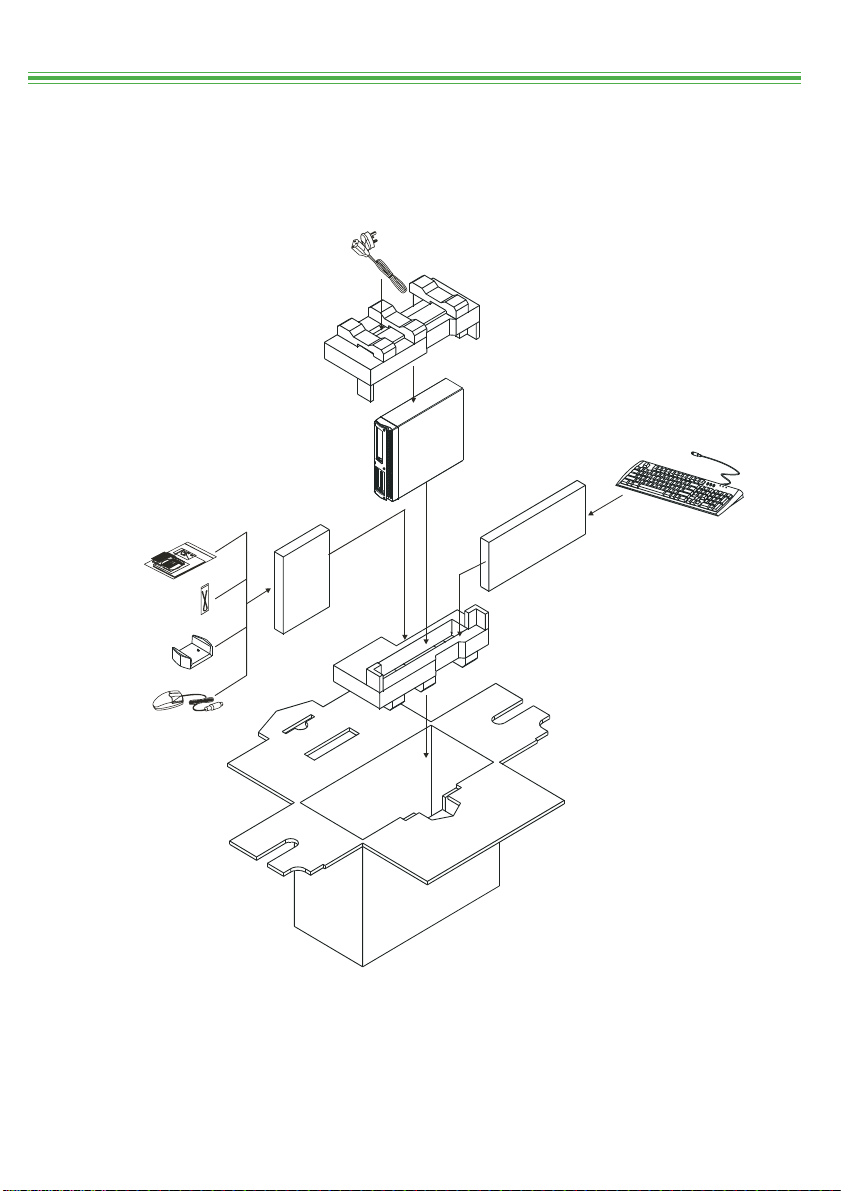
Items included in the package/
Software and Manuals/
Ⱇ㋥⎟༇Ҫ/࠰ࡈ࠻࠙ࠚࠕߣࡑ࠾ࡘࠕ࡞
Cables/ℭ/
ࠤࡉ࡞
Foot Stand/⌴ಛ/
ࡈ࠶࠻ࠬ࠲ࡦ࠼
包裝內含物包裝內含物
包裝內含物/
包裝內含物包裝內含物
Power Cord/テℭ/㔚Ḯࠦ࠼
P C
パッケージに含まれるアイテムパッケージに含まれるアイテム
パッケージに含まれるアイテム
パッケージに含まれるアイテムパッケージに含まれるアイテム
*Keyboard (Option)/
*⼬Ჸ!)ⴇᮣ*/
*ࠠࡏ࠼ࠝࡊ࡚ࠪࡦ
*Mouse (Option)/
*ᝲ㔱!(ⴇᮣ*/!
*ࡑ࠙ࠬ㧔ࠝࡊ࡚ࠪࡦ㧕
Specifications marked with “Option” are subject to change without notice.
ᐼ⥇ᣆȶⴇᮣȷ≜ʡ⣴ጂሸ⩑ሪඵʄס⠘ⳈᵨȰ!
!!!ޟࠝࡊ࡚ࠪࡦޠߢࡑࠢߐࠇߚ᭽ߪޔ᧪๔ߥߒߦᄌᦝߔࠆߎߣ߇ࠅ߹ߔޕ
Page 6

GIGABYTE FB Series Quick Insatllation Guide / GIGABYTE FB系列快速安裝指南 /
GIGABYTE FBシリーズクリックインストールガイド
5
Installing the System/
Installing the Hard Disk Drive/
付ける付ける
付ける
付ける付ける
1. Remove the screw from the rear casing, and slide the upper casing toward the front panel as
shown.
將螺絲從後方機殼上卸下,然後將上方機殼往前面板的方向滑動,如圖所示。
背面ケーシングからネジを取り外し、図に示すように上部ケーシングを前面パネルの方に
スライドさせます。
Remove/
卸下/
取り外し
2. After loosening the 3 front screws and pulling out the optical disk drive, loosen the
screws of the hard disk drive rack and then remove the hard disk drive rack.
當卸下3 顆前方螺絲並取出光碟機之後,再卸下硬碟機架的螺絲,並拆下硬碟機架。
3本の前面ネジを緩め光ディスクドライブを引き出した後、ハードディスクドライ
ブのラックのネジを緩めハードディスクドライブのラックを取り外します。
安裝系統安裝系統
安裝系統/
安裝系統安裝系統
安裝硬碟機安裝硬碟機
安裝硬碟機/
安裝硬碟機安裝硬碟機
システムをインストールするシステムをインストールする
システムをインストールする
システムをインストールするシステムをインストールする
ハードディスクドライブを取りハードディスクドライブを取り
ハードディスクドライブを取り
ハードディスクドライブを取りハードディスクドライブを取り
Pull and lift the optical
disk drive rack./
取出光碟機架。/ 光
ディスクドライイブ
のラックを引きなが
ら持ち上げます
3. Put the hard disk drive into the rack, and align the screws at the screw holes.
將硬碟機放入機架中,然後將螺絲對準螺絲孔。
ハードディスクドライブをラックにセット
し、ネジをネジ穴に合わせます。
Loosen the screws, and
remove the hard disk drive
rack./ 卸下螺絲,然後拆下
硬碟機架。/ ネジを緩め、
ハードディスクドライブの
ラックを取り外し
Page 7

GIGABYTE FB Series Quick Installation Guide / GIGABYTE FB系列快速安裝指南 /
GIGABYTE FBシリーズクリックインストールガイド
安裝安裝
CPUCPU
CPUCPU
Installing the CPU/
The FB Series accommodates two types of CPU and heatsinks, depending upon which
motherboard is installed.
根據所安裝的主機板類型,F B 系列可安裝兩型C P U 與散熱片。
FB シリーズは取り付けているマザーボードに従って、2 種類のCPU とヒートシンクを提供しま
す。
If you need to set up the frequency of the CPU, please do so in the BIOS SETUP. Refer to
the Motherboard User's Manual for the setup.
如果您需要設定C P U 的頻率,請在BIOS SETUP中設定。關於設定的操作指示,
請參考主機板使用者。
CPU の周波数をセットアップする必要がある場合、BIOSセットアップで行ってく
ださい。セットアップについては、マザーボードユーザー
ズマニュアルを参照し
てください。
安裝
安裝安裝
CPU/
CPUCPU
を取り付けるを取り付ける
CPU
を取り付ける
CPUCPU
を取り付けるを取り付ける
Type A (Intel Pentium® 4 LGA775 CPU)
型型
A
型
(Intel Pentium® 4 LGA775 CPU)
型型
タイプタイプ
タイプA(Intel Pentium® 4 LGA775 CPU)
タイプタイプ
1. Unhook the CPU socket lever from the socket as shown
by the arrows.
請依照圖上的箭頭指示方向拉開CPU座上的CPU固定
桿。
矢印で示すように、ソケットからCPUソケットレバー
のフックを外します。
6
2. Rotate the security cover and lever up.
旋轉安全蓋,將其往上掀起。
セキュリティカバーを回転しレバーを上に上げます。
3. There is a gold triangle located at one corner of the
CPU. Align the indented corner of the CPU with the
triangle and gently insert the CPU into the socket in
a straight and downwards motion. Avoid twisting
or bending the CPU while inserting it; otherwise,
you may damage the CPU.
在C P U 的其中一角上有一個金色的三角形符號。
請將C P U 往內縮的一角對準三角形的方向,
然後輕輕地、垂直地將C P U 插入C P U 座中。
在插入C P U 的過程中,請避免轉動或彎曲CPU,
否則可能會損壞C P U 。
CP U の1つの隅には金色の三角形があります。
CPU の目的の隅を三角形に合わせ、CPUをソケ
ットにまっすぐ下向きに挿入します。CPUを
挿入している間ねじったり曲げたりしないで
ください。CP Uが損傷すること があります。
Gold triangle/
金色三角形/
金の三角形
Page 8

GIGABYTE FB Series Quick Insatllation Guide / GIGABYTE FB系列快速安裝指南 /
GIGABYTE FBシリーズクリックインストールガイド
4. Lower the security cover and return the CPU socket lever to its original position.
按下安全蓋,然後轉動C P U 座固定桿,使其回到原有位置。
セキュリティカバーを下げ、CP U ソケットレバーを元の位置に戻します。
5. Spread heat dispersal paste evenly on the top of the CPU.
將散熱膏均勻塗抹於C P U 的上方表面。
熱放散糊をCP U の上部に均等に広げます。
6. Pull the pins up on the heatsink as shown.
將散熱片上的固定柱往上拉,如圖所示。
図のように、ヒートシンクのピンを引き出します。
7. Place the heatsink over the CPU and insert the heatsink pegs
into the motherboard. After the pegs are inserted, rotate them
clockwise to lock them in place.
將散熱片放到C P U 上,然後將散熱釘插入主機板中。
插入散熱釘之後,請以順時針方向旋轉以將散熱片固定
好。
CPUの上にヒートシンクを置き、ヒートシンクのペグをマ
ザーボードに挿入します。ペグを挿入した後、時計回りに
回転し正しい位置にロックします。
7
8. Plug the heatsink fan power cable into the CPU fan power
connector on the motherboard.
將散熱風扇電源線插到主機板上的C P U 風扇電源接頭上。
ヒートシンクファンの電源ケーブルを、マザーボードの
CPU ファン電源コネクタに差し込みます。
Page 9

GIGABYTE FB Series Quick Installation Guide / GIGABYTE FB系列快速安裝指南 /
GIGABYTE FBシリーズクリックインストールガイド
Type B (Intel Pentium® 4 Socket 478 CPU)/
型型
B
型
(Intel Pentium® 4 Socket 478 CPU)/
型型
タイプタイプ
タイプB (Intel Pentium® 4 Socket 478 CPU)
タイプタイプ
1. Raise the CPU socket lever as shown by the arrows.
依照箭頭指示方向拉起C P U 座固定桿。
矢印で示すように、CPUのソケットレバーを持ち上げます。
2. Place the CPU into the CPU socket, aligning the pin 1 of the CPU
with pin 1 of the socket.
將C P U 插入C P U 座中,並使C P U 的針腳1 對準插槽的針腳1 。
CP U のピン1をソケットのピン1に合わせながら、CP U を CP U
ソケットに取り付けます。
3. Lower the CPU socket lever to secure the CPU.
按下C P U 座固定桿以固定C P U 。
CPUソケットレバーを下げ、CP Uを固定します。
4. Apply heat dispersion paste evenly to the top of the CPU.
將散熱膏均勻塗抹於C P U 上方表面。
熱放散糊をCP U の上部に均等に塗ります。
8
5. Place the heatsink on the CPU and secure it with the locking
levers.
將散熱片安裝於C P U 上,並用固定桿固定好CPU。
ヒートシンクをCPU に取り付け、ロッキングレバーで固定します。
6. Plug the heatsink fan power cable into the CPU fan power
connector on the motherboard.
將散熱風扇電源纜線插到主機板上的CPU風扇電源接頭上。
ヒートシンクファンの電源ケーブルを、マザーボードの
CPUファン電源コネクタに差し込みます。
Page 10

GIGABYTE FB Series Quick Insatllation Guide / GIGABYTE FB系列快速安裝指南 /
GIGABYTE FBシリーズクリックインストールガイド
9
Installing Memory/
When installing the memory, align the notch on the bottom with the memory
slot on the motherboard. For successful installation, the hooks on both sides must be latched
completely into the grooves.
安裝記憶體時,請將底部的凹槽對準主機板上的記憶體插槽。要成功安裝記憶
體,插槽兩側的勾鎖必須完全拴緊到溝槽上。
メモリを取り付けるとき、底面の切り込みをマザーボードのメモリスロットに合わせます。
取り付けを正常に行うため、両方の側のフックを溝にしっかりかける必要があります。
Grooves on both sides/兩側的溝槽/両側の溝
Hooks/勾鎖/フック
安裝記憶體安裝記憶體
安裝記憶體/
安裝記憶體安裝記憶體
メモリを取り付けるメモリを取り付ける
メモリを取り付ける
メモリを取り付けるメモリを取り付ける
Notch/凹槽/切り込み
DDR Memory/
記憶體記憶體
DDR
記憶體/
記憶體記憶體
メモリメモリ
DDR
メモリ
メモリメモリ
Page 11

GIGABYTE FB Series Quick Installation Guide / GIGABYTE FB系列快速安裝指南 /
GIGABYTE FBシリーズクリックインストールガイド
10
Connecting Cables/
ケーブルを接続するケーブルを接続する
ケーブルを接続する
ケーブルを接続するケーブルを接続する
The FB series accommodates two types of
hard disk drive: SATA or IDE.
FB系列可安裝兩種硬碟機:SATA或IDE。
FBシリーズは、次の2種類のハードディスクドライブを提供します。SATAとIDE。
IDE Hard Disk Drive/IDE
ハードディスクドライブハードディスクドライブ
IDE
ハードディスクドライブ
ハードディスクドライブハードディスクドライブ
2. Connect the connector of the power supply to the power supply socket of the hard disk drive.
將電源供應器接頭連接到硬碟機的電源供應插槽上。
電源装置のコネクタをハードディスクドライブの電源装置のソケットに接続します。
連接排線連接排線
連接排線/
連接排線連接排線
硬碟機硬碟機
硬碟機/
硬碟機硬碟機
Power Supply Socket/
電源供應插槽/
電源装置のソケット
Connect to hard
disk drive/
連接到硬碟機上/
ハードディス
クドライブに接
続します
SATA Hard Disk Drive/SATA硬碟機/
ハードディスクドライブハードディスクドライブ
SATA
ハードディスクドライブ
ハードディスクドライブハードディスクドライブ
3. After the above steps are completed, reinstall the hard disk drive rack back to the casing
and tighten the screws.
完成上述步驟之後,請將硬碟機架重新安裝到機殼上,並鎖緊螺絲。
上のステップが完了したら、ハードディスクドライブのラックをケーシングに
取り付け直し、ネジを締めます。
Tighten the screws on the hard
disk drive rack./
鎖緊硬碟機架上的螺絲。/
ハードディスクドライブのラック
のネジを締め付けます。
Page 12

GIGABYTE FB Series Quick Insatllation Guide / GIGABYTE FB系列快速安裝指南 /
GIGABYTE FBシリーズクリックインストールガイド
4. Connect the other end of the IDE bus cable to the data bus slot labeled as IDE-1 on the
motherboard. Connect the other end of the SATA cable to the SATA-1 connector.
將IDE排線的另一端連接到主機板上標示為IDE-1的資料匯流排插槽。
將SATA排線的另一端連接到SATA-1接頭上。
IDEバスケーブルのもう一方の端を、マザーボードにIDE-1とラベルされたデー
タバススロットに接続します。SATAケーブルのもう一方の端をSATA-1コネクタに
接続します。
Connect to the data bus slot labeled as IDE-1
on the motherboard./連接到主機板上標示為
IDE-1的資料匯流排插槽。/ マザーボードの
IDE-1とラベルされたデータバススロットに接
続します。
Connect to the data bus slot labeled as
SATA-1 on the motherboard./連接到主機
板上標示為SATA-1的資料匯流排插槽。/
マザーボードのSATA-1とラベルされた
データバススロットに接続します。
11
5. Reinstall the optical disk drive back into position on the casing, and tighten the screws.
將光碟機重新安裝回機殼上的原有位置,並鎖緊螺絲。
光ディスクドライブをケーシングの元の場所に再び取り付け、ネジで締め付けます。
6. Reconfirm that all connections are properly made.
請再次確認所有連接皆已正確完成。
すべてのコネクタが正しく取り付けられていることを再確認します。
7. Install the upper casing and tighten the screws back into place.
安裝上方機殼,並將螺絲鎖回正確位置。
上部ケーシングを取り付け、ネジで元の場所に締め付けます。
Page 13

GIGABYTE FB Series Quick Installation Guide / GIGABYTE FB系列快速安裝指南 /
GIGABYTE FBシリーズクリックインストールガイド
12
FB Series Components/FB
Front Panel Components/
CD-ROM Eject Button/光
CD-ROMイジェクトボタン
CD-ROM Tray/
CD-ROMトレイ
CD-ROM Eject Button/
CD-ROMイジェクト
*Card Reader LED/
*讀卡機LED指示燈/
*カードリーダーLED
* Items are factory optional./
該項目為原廠選用配備。
アイテムは出荷時のオプションです。
系列組件系列組件
系列組件/FB
系列組件系列組件
碟退出按鈕/
光碟托盤/
光碟退出按鈕/
CD-ROM Tray/
光碟托盤/
CD-ROMトレイ
*USB
*CF/MD
*SM
*MS/MS PRO
*SD/MMC
シリーズコンポーネントシリーズコンポーネント
シリーズコンポーネント
シリーズコンポーネントシリーズコンポーネント
前面板組件前面板組件
前面板組件/
前面板組件前面板組件
面パネルコンポーネント面パネルコンポーネント
面パネルコンポーネント
面パネルコンポーネント面パネルコンポーネント
Power Button/
電源按鈕/
電源ボタン
Power LED/
電源LED指示燈/
電源LED
HDD LED/硬碟
LED指示燈
Audio Output/
聲音輸出/
オーディオ出力
MIC Port/
麥克風連接埠/
マイクポート
USB Ports/
USB連接埠/
USBポート
Power Button/
電源按鈕/
電源ボタン
Power LED/電源
LED指示燈/
電源LED
HDD LED/硬碟
LED指示燈
*IEEE1394 Port/
*IEEE1394連接埠/
*IEEE1394ポート
Audio Output/聲音輸出
オーディオ出力
MIC Port/
麥克風連接埠/
マイクポート
USB Ports/
USB連接埠/
USBポート
*SPDIF Port/
*SPDIF連接埠/
*SPDIFポート
Page 14

GIGABYTE FB Series Quick Insatllation Guide / GIGABYTE FB系列快速安裝指南 /
GIGABYTE FBシリーズクリックインストールガイド
13
Rear Panel Components/
Version 1.0/1.0
Power Socket/電源插槽/
キーボードポート(PS/2)
USB Ports/USB連接埠/
電源ソケット
Keyboard Port(PS/2)/
鍵盤連接埠(PS/2)/
USB Ports/
USB連接埠
COM Port/COM連接埠/
COMポート
VGA
USBポート
MIC In/麥克風輸入/
マイク入力
Power Socket/電源插槽/電源ソケット
Keyboard Port (PS/2)/鍵盤連接埠 (PS/2)/
キーボードポート(PS/2)
SPDIF out/SPDIF輸出/SPDIF出力
SPDIF in/SPDIF輸入/SPDIF入力
VGA Port/VGAポート
USB Ports/USB連接埠/USBポート
MIC In/麥克風輸入/マイク入力
Side speaker out/側面揚聲器輸出/
側面スピーカー出力
後面板組件後面板組件
後面板組件/
後面板組件後面板組件
版本版本
バージョンバージョン
版本/
バージョン1.0
版本版本
バージョンバージョン
Voltage Switch/
電壓切換開關/
電圧スイッチ
Mouse Port
(PS/2)/
滑鼠連接埠
(PS/2)/
マウスポート
(PS/2)
LPT Port/LPT連接埠/
LPTポート
LAN Port/LAN連接埠/
LANポート
Audio In/聲音輸入/
オーディオ入力
Audio Out/聲音輸出/
オーディオ出力
Version 3.0/3.0
背面パネルコンポーネント背面パネルコンポーネント
背面パネルコンポーネント
背面パネルコンポーネント背面パネルコンポーネント
Version 2.0/2.0
Power Socket/
電源插槽/
電源ソケット
Keyboard Port(PS/2)/
鍵盤連接埠(PS/2)
COM Port/COM連接埠/
版本版本
版本/
版本版本
COMポート
VGA
USB Ports/
USB連接埠
USBポート
MIC In/
麥克風輸入/
マイク入力
バージョンバージョン
バージョン3.0
バージョンバージョン
Voltage Switch/電壓切換開關/電圧スイッチ
Mouse Port (PS/2)/
滑鼠連接埠(PS/2)/ マウスポート(PS/2)
LPT Port/LPT連接埠/
LPTポート
LAN Port/
LAN連接埠/
LANポート
Audio In/聲音輸入/オーディオ入力
Rear speaker out/後方揚聲器輸出/
背面スピーカー出力
Center/Subwoofer speaker out/
中央/重低音揚聲器輸出/中央/ サブウーファス
*IEEE1394 Ports/*IEEE1394連接埠/
*IEEE1394ポート
版本版本
バージョンバージョン
版本/
バージョン2.0
版本版本
バージョンバージョン
Voltage Switch/
電壓切換開關/
電圧スイッチ
Mouse Port (PS/2)/
滑鼠連接埠(PS/2)/
マウスポート(PS/2)
LPT Port/LPT連接埠/
LPT ポート
LAN Port/LAN連接埠/
LANポート
Audio In/聲音輸入/
オーディオ入力
Audio Out/聲音輸出/
オーディオ出力
*IEEE1394 Ports/
*IEEE1394 連接埠/
*IEEE1394ポート
Audio Out (Front Speaker Out)/
聲音輸出( 前方揚聲器輸出) /
オーディオ出力
(前面スピーカー出力)
* Items are factory optional.
該項目為原廠選用配備。
アイテムは出荷時のオプションです。
Page 15

GIGABYTE FB Series Quick Installation Guide / GIGABYTE FB系列快速安裝指南 /
GIGABYTE FBシリーズクリックインストールガイド
14
Remarks/
1. It is recommended to use a high-quality optical disk to avoid the risk of broken disks during the
operation of the high-speed optical disk drive.
建議您使用高品質光碟機,以避免於高速操作光碟機時損壞光碟。
高速光ディスクドライブを操作中にディスクが破損する危険を避けるために、高品質の光
ディスクを使用することをお勧めします。
2. Some of the items labeled with “*” may be different from the hardware specifications listed in
this manual, and such items are based on the actual shipment.
部分標記有“* ”的項目可能與本手冊中所標記的硬體規格有所不同,此類項目需視
實際出貨項目為準。
「*」のラベルが付いたアイテムの中には本書でリストアップしたハードウェア仕様 と異
なるものがありますが、そのようなアイテムは実際の出荷に基づいています。
3. If you want to obtain the most updated information of the drivers, please link to the following
website:
http://www.gigabyte.com.tw/products/plat_index.htm
如果您想要取得驅動程式的最新資訊,請連結以下網站:
http://www.gigabyte.com.tw/products/plat_index.htm
ドライバの最新の更新情報の入手については、次のWebサイト:
http://www.gigabyte.com.tw/products/plat_index.htmにリンクしてください。
Cautions for Safety/
1. There is a risk of explosion if the Lithium battery of the system is not instaleld properly.
Therefore, make sure you are using the same branded battery or equivalent one
recommended by the manufacturer when replacing the batteries. Follow the instructions given
by the manufacturer to handle the disposed batteries.
如未正確安裝系統鋰電池,可能會有爆炸的危險。因此,更換電池時,請使用製造商
指定的品牌或相等類型的電池。若要丟棄用後的電池,請依照製造商的指示來處理。
システムのリチウムバッテリを正しく取り付けないと、爆発の危険があります。 従って、
バッテリを交換するときは同じブランドのバッテリまたはメーカーが推奨 するものと同等
のバッテリを使用していることを確認してください。
メ[カーの指示に従って、使用済みバッテリを処分してください。
注意注意
注意
注意注意
//
/
//
備考備考
備考
備考備考
安全注意事項安全注意事項
安全注意事項/
安全注意事項安全注意事項
安全に関する注意事項安全に関する注意事項
安全に関する注意事項
安全に関する注意事項安全に関する注意事項
2. When the users install a modem card on their own, please pay attention to the following:
當使用者自行安裝數據卡時,請注意以下細節:
ユーザーが自分でモデムカードを取り付けるとき、以下の点に注意してください:
i. Please avoid using the telephone wire smaller than that of the No. 26 AWG to prevent
fire accidents.
請避免使用細於No.26AWG的電話線,以防發生火災的意外。
火災の恐れがあるため、No.26AWGより細い電話線の使用は避けてください。
ii.When the modem card is installed or uninstalled, please unplug the telephone line from
the socket.
當安裝或解除安裝數據卡時,請將電話線從插槽上拔下。
モデムカードのインストール/アンインストールの際は、ソケットから電話線
を抜いてください。
 Loading...