

Page 1

CLN4C44
ConnectX®-4 Quad Port 25Gb/s Adapter
User Manual
Rev. 1.0
Page 2
- 2 -
Chapter 1 Features
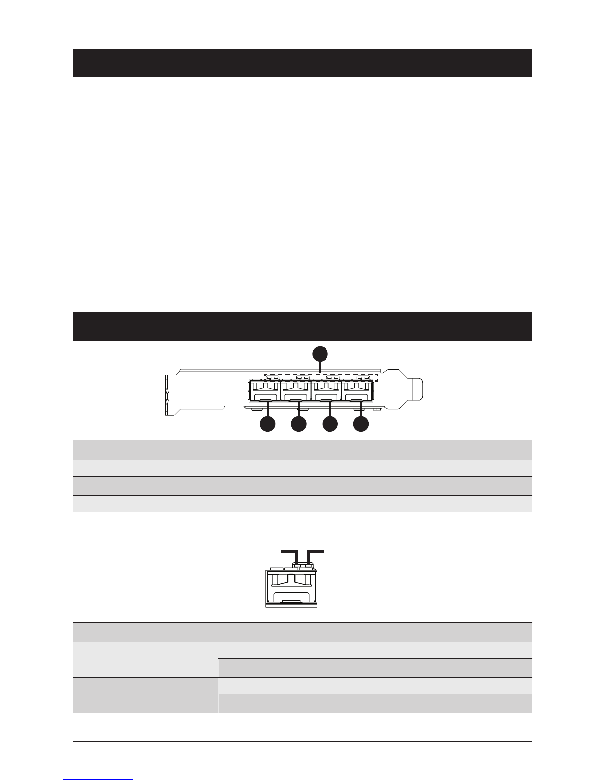
Chapter 2 Components
The following is a list of features for your CLN4C44 Network Adapter:
LED Behavior
• Four SPF28 LAN Connectors
• MD2 Low-Profile Form Factor
• Dual Mellnox ConnectX
®
- 4 Lx EN Ethernet
Controller
• CPU Offloading of Transport Operations
• Low Latency RDMA over Converged
Ethernet (RoCE)
• Jumbo Frames Support Up to 9.6kB
• End-to-End QoS and Congestion Control
• RoHS-R6
• Up to 4 x 25Gb/s Ethernet per port
• PCIe 3.0 x16 Interface**
• Hardware Offloads for VXLAN, NVGRE and
GENEVE Encapsulated Traffic
• Hardware-based I/O Virtualization
• Mellanox PeerDirect™ Communication
Acceleration
• PXE Support
• Erasure Coding Offload
1
2 3 4 5
No.
1.
2.
3.
Description
LEDs (see the table below for LED behavior)
LAN Port 1
LAN Port 2
No.
4.
5.
Description
LAN Port 3
LAN Port 4
LED
Speed (Physical Link)
Activity (Logical Link)
Color
Green
Green
Yellow
Yellow
Behavior
On
Off
Blinking
Off
Description
Port Physical Link
No Connection
Port Access
No Access
Speed (Green) Activity (Yellow)
**NOTE: Based on this product controller specification, the PCIe x16 interface needs to re-defined to 1 x PCIe x8 + 1 x PCIe x8 bus
in the BIOS setting, to allow system detection of 4 Ethernet ports.
Page 3

- 3 -
Chapter 2 Components (Cont.)
NCSI Connector Pin Definitions
No.
1.
Description
NCSI Connector (see the table below for pin definitions)
No.
2.
Description
Chip Heatsink Connector
1
2
12
19 20
NCSI_CLK
NCSI_RX_D0
NCSI_RX_D1
NCSI_CRS_DV
NCSI_RX_ER
P3V3_AUX
NCSI_TX_D1
NCSI_TX_D0
NCSI_TX_EN
NCSI_PRESENT
P3V3_AUX_EN
GND
GND
GND
GND
GND
GND
GND
GND
P3V3_AUX
Pin 2
Pin 20
Pin 1
Pin 19
Page 4

- 4 -
Chapter 3 Pre-Installation Instructions
Before installing the CLN4C44 Network Adapter ensure that you review the contents of this
chapter.
Hardware Requirements
In order for the CLN4C44 Network Adapter to work properly in your system, ensure that your
system meets the following mimimum hardware requirements:
•
A system with a PCI Express x16 slot.
Also ensure that the following connection requirements are met:
•
Interoperable with EDR InfiniBand or 1/10/25 Gb/s Ethernet switches
Supported Cables
For a list of supported cables refer to the following website:
http://download.gigabyte.eu/FileList/QVL/server_accessory_qvl_cln4c44_v1.0.pdf
Software Requirements
In order for the CLN4C44 Network Adapter to work properly in your system, ensure that your
system has one of the following operating systems installed:
•
Windows Server 2012 R2 x64 Update 1
•
Windows Server 2016 x64
•
Red Hat Enterprise Linux server 7.3 x64
•
Red Hat Enterprise Linux server 6.8 x64
•
SUSE Linux Enterprise 12 SP2 x64
•
SUSE Linux Enterprise 11 Service Pack 4 x64
•
Ubuntu 16.04.2 LTS x64
•
Ubuntu 14.04.5 LTS x64
Safety Precautions
This adapter is beting installed in a system that operates with voltages that can be
lethal. Before opening the chassis of the system, observe the following precautions
to avoid injury and prevent damage to the system.
•
Remove any metallic objects from your hands and wrists.
•
Make sure to use only insulated tools.
•
Verify that the system is powered off and unplugged.
•
Use an ESD strap or other anti-static devices/equipment.
Page 5

- 5 -
Chapter 4 Installation Instructions
Before you begin the installation process, ensure that your system has been
powered off and unplugged, and that you have reviewed all the precautions in the
Pre-Installation Instructions chapter.
To install the CLN4C44 Network Adapter into your system follow the instructions below:
1. Open the chassis of the system you want to install the adapter in.
2. Locate the PCI Express x16 slot you want to install the adapter in.
3. Remove any existing brackets covering the slot.
4. Align the adapter to the slot.
5. Ensure that the ports on the adapter extend through the opening for the PCI Express x16 slot,
then while applying even pressure at both corners of the top side of the adapter insert the
adapter into the PCI Express slot until it is firmly seated.
Page 6

Chapter 4 Installation Instructions (Cont.)
NOTE: The cable connection is required to download the drivers for the adapter.
As a result, failure to connect the SFP cable will prevent completion of the installation
process.
- 6 -
6. Once the adapter is properly seated, the ports on the adapter should be properly aligned with
the slot opening, and the adapter faceplate should be visible against the system chassis.
7. Secure the adapter with adapter clips or screws.
8. Connect an SFP cable with internet access to LAN port 1 (for supported cables, refer to the
Supported Cables section in Chapter 3).
To remove the adapter from the system reverse the installation process described above.
 Loading...