

Page 1

GA-C621-SU8
User's Manual
Rev. 1001
Page 2
Page 3

Copyright
© 2018 GIGA-BYTE TECHNOLOGY CO., LTD. All rights reserved.
The trademarks mentioned in this manual are legally registered to their respective owners.
Disclaimer
Information in this manual is protected by copyright laws and is the property of GIGABYTE.
Changes to the specications and features in this manual may be made by GIGABYTE without
prior notice.
No part of this manual may be reproduced, copied, translated, transmitted, or published in any
form or by any means without GIGABYTE's prior written permission.
For product-related information, check on our website at: https://www.gigabyte.com
Page 4

Table of Contents
GA-C621-SU8 Motherboard Layout ................................................................................5
Box Contents ...................................................................................................................6
Chapter 1 Hardware Installation .....................................................................................7
1-1 Installation Precautions .................................................................................... 7
1-2 Product Specications ...................................................................................... 8
1-3 Installing the CPU .......................................................................................... 11
1-4 Installing the Memory ..................................................................................... 12
1-5 Back Panel Connectors .................................................................................. 13
1-6 Internal Connectors ........................................................................................ 15
Chapter 2 BIOS Setup .................................................................................................. 26
2-1 Startup Screen ............................................................................................... 26
2-2 Main ............................................................................................................... 27
2-3 Advanced ....................................................................................................... 28
2-4 Platform Conguration ................................................................................... 31
2-5 Socket Conguration ...................................................................................... 33
2-6 Server Mgmt .................................................................................................. 35
2-7 Security .......................................................................................................... 36
2-8 Boot ................................................................................................................ 37
2-9 Save & Exit ..................................................................................................... 38
Chapter 3 Application....................................................................................................39
Regulatory Statements .............................................................................................. 48
Contact Us ................................................................................................................ 49
- 4 -
Page 5
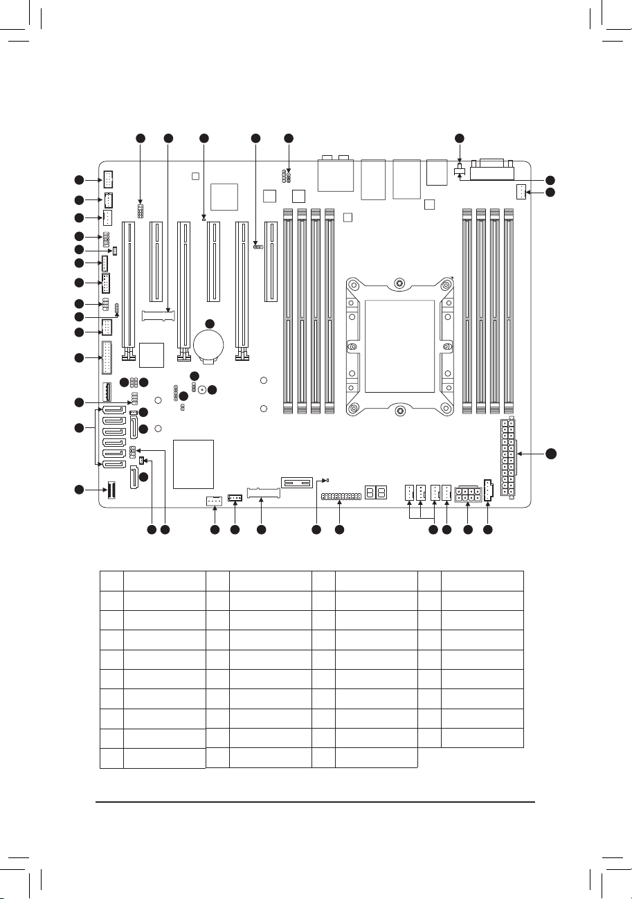
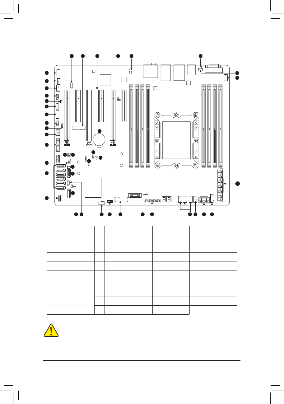
GA-C621-SU8 Motherboard Layout
39
33
34
25
4
8
5
10
7
9
18
16
1415
6
29
32
12
28
28
13 11 25 17 31 35 19 25 24 27 20
38
22
3
23
123730
36
21
25
26
1 BMC_VGA
2 BMC_WATCHD
3 Buzzer
4 COMB
5 SMB_IPMB
6 I_SGPIO1
7 I_SGPIO2
8 WOL
9 SMB
10 TPM
11 S_SGPIO
12 SATA_DOM0
13 SATA_DOM1
14 VRM_SCL
15 VRM_SDA
16 FUSB30
17 VROC
18 FUSB2
19 F_PANEL
20 PMBUS
21 UID
22 CLR_CMOS
23 CI
24 CPU_FAN1
25 SYS_FAN1~6
26 AT X
27 ATX8P
28 S-SATA0~1
29 I-SATA0~5
30 PCIEX4_M2
- 5 -
31 PCIEX2_M2
32 F_USB30C
33 F_AUDIO
34 THB_C
35 F_LED1
36 F_LED2
37 BMC_LED1
38 B AT
39 SMB_VMD
Page 6

Box Contents
5 GA-C621-SU8 motherboard
5 Motherboard driver disk 5 Six SATA cables
5 Quick Installation Guide 5 I/O Shield
- 6 -
Page 7

Chapter 1 Hardware Installation
1-1 Installation Precautions
The motherboard contains numerous delicate electronic circuits and components which can become
damaged as a result of electrostatic discharge (ESD). Prior to installation, carefully read the user's
manual and follow these procedures:
• Prior to installation, make sure the chassis is suitable for the motherboard.
• Prior to installation, do not remove or break motherboard S/N (Serial Number) sticker or
warranty sticker provided by your dealer. These stickers are required for warranty validation.
• Always remove the AC power by unplugging the power cord from the power outlet before
installing or removing the motherboard or other hardware components.
• When connecting hardware components to the internal connectors on the motherboard, make
sure they are connected tightly and securely.
• When handling the motherboard, avoid touching any metal leads or connectors.
• It is best to wear an electrostatic discharge (ESD) wrist strap when handling electronic
components such as a motherboard, CPU or memory. If you do not have an ESD wrist strap,
keep your hands dry and rst touch a metal object to eliminate static electricity.
• Prior to installing the motherboard, please have it on top of an antistatic pad or within an
electrostatic shielding container.
• Before connecting or unplugging the power supply cable from the motherboard, make sure
the power supply has been turned off.
• Before turning on the power, make sure the power supply voltage has been set according to
the local voltage standard.
• Before using the product, please verify that all cables and power connectors of your hardware
components are connected.
• To prevent damage to the motherboard, do not allow screws to come in contact with the
motherboard circuit or its components.
• Make sure there are no leftover screws or metal components placed on the motherboard or
within the computer casing.
• Do not place the computer system on an uneven surface.
• Do not place the computer system in a high-temperature or wet environment.
• Turning on the computer power during the installation process can lead to damage to system
components as well as physical harm to the user.
• If you are uncertain about any installation steps or have a problem related to the use of the
product, please consult a certied computer technician.
• If you use an adapter, extension power cable, or power strip, ensure to consult with its installation
and/or grounding instructions.
- 7 -
Page 8
1-2 ProductSpecications
CPU 1st and 2nd Generation Intel® Xeon® Scalable Processors, LGA 3647 Socket P
(Narrow) with 2 UPI support of up to 10.4 GT/s, CPU TDP support up to 165W
Chipset Intel® C621 Chipset
Memory 8 x DDR4 DIMM sockets supporting up to 1 TB of system memory
6 channel memory architecture
Support for DDR4 2666 MHz memory modules if use a Skylake CPU
Support for DDR4 2933 MHz memory modules if use a Cascade lake CPU
Support for ECC RDIMM/RDIMM 3DS/LRDIMM/LRDIMM 3DS memory modules
Onboard
Graphics
Audio Realtek® ALC1220-VB2 codec
LAN
Expansion Slots 1 x PCI Express x16 slot, running at x16 (PCIEX16_5)
Storage Interface Chipset:
USB Chipset+ ASMedia® USB 3.1 Gen 2 Controller:
ASPEED® AST2500:
- 1 x D-Sub port, supporting a maximum resolution of 1920x1200@60 Hz
* The back panel line out jack supports DSD audio.
High Denition Audio
2/4/5.1/7.1-channel
Support for S/PDIF Out
1 x Realtek RTL8211E chip (10/100/1000 Mbit) (LAN1)
2 x Intel® 210AT GbE LAN chips (10/100/1000 Mbit) (LAN2, LAN3)
* For optimum performance, if only one PCI Express graphics card is to be installed,
be sure to install it in the PCIEX16 slot.
2 x PCI Express x16 slots, running at x8 (PCIEX8_1, PCIEX8_3)
2 x PCI Express x8 slots, running at x8 (PCIEX8_4, PCIEX8_6)
1 x PCI Express x8 slot, running at x4 (PCIEX4_2)
(All of the PCI Express slots conform to PCI Express 3.0 standard.)
- 1 x M.2 connector (Socket 3, M key, type 2260/2280 SATA and PCIe x2 SSD
support) (PCIEX2_M2)
- 1 x M.2 connector (Socket 3, M key, type 2242/2260/2280 PCIe x4/x2 SSD
support) (PCIEX4_M2)
- 2 x SATA 6Gb/s connectors (S-SATA0~1)
- 6 x SATA 6Gb/s connectors (I-SATA0~5)
- Support for RAID 0, RAID 1, RAID 5, and RAID 10
- 2 x USB 3.1 Gen 2 Type-A ports (red) on the back panel
Chipset:
- 5 x USB 3.1 Gen 1 ports (2 ports on the back panel, 1 port onboard, 2 ports
available through the internal USB header)
- 2 x USB 2.0/1.1 ports available through the internal USB header
- 8 -
Page 9

Internal
Connectors
Back Panel
Connectors
1 x 24-pin ATX main power connector
1 x 8-pin ATX 12V power connector
1 x CPU fan header
6 x system fan headers
8 x SATA 6Gb/s connectors
2 x SATA DOM power headers
2 x M.2 Socket 3 connectors
1 x front panel header
1 x front panel audio header
1 x USB Type-C™ port, with USB 3.1 Gen 1 support
1 x USB 3.1 Gen 1 header
1 x USB 2.0/1.1 header
1 x Thunderbolt™ add-in card connector
1 x Trusted Platform Module (TPM) header
1 x serial port header
1 x chassis intrusion header
1 x Clear CMOS jumper
3 x SATA SGPIO headers
1 x BMC_VGA jumper
1 x BMC_WATCHD jumper
1 x wake on LAN header
1 x IPMB connector
1 x SMB jumper
1 x VRM SMB Clock jumper
1 x VRM SMB Data jumper
1 x Intel® VROC Upgrade Key header
1 x NVMe SMBus (I2C) header
1 x buzzer
1 x NVMe SMBUS Control header
1 x D-Sub port
1 x serial port
1 x UID button
2 x USB 3.1 Gen 2 Type-A ports (red)
2 x USB 3.1 Gen 1 ports
3 x RJ-45 ports
1 x optical S/PDIF Out connector
5 x audio jacks
- 9 -
Page 10
I/O Controller ASPEED® AST2500 BMC chip
Hardware
Monitor
Voltage detection
Temperature detection
Fan speed detection
Fan speed control
* Whether the fan speed control function is supported will depend on the fan you install.
BIOS 1 x 256 Mbit ash
Use of licensed AMI BIOS
PnP 1.0a, DMI 2.7, WfM 2.0, SM BIOS 2.7, ACPI 5.0
Operating
System
Support for Windows 10 64-bit
Form Factor ATX Form Factor; 30.5cm x 24.4cm
* GIGABYTE reserves the right to make any changes to the product specications and product-related information without
prior notice.
- 10 -
Page 11
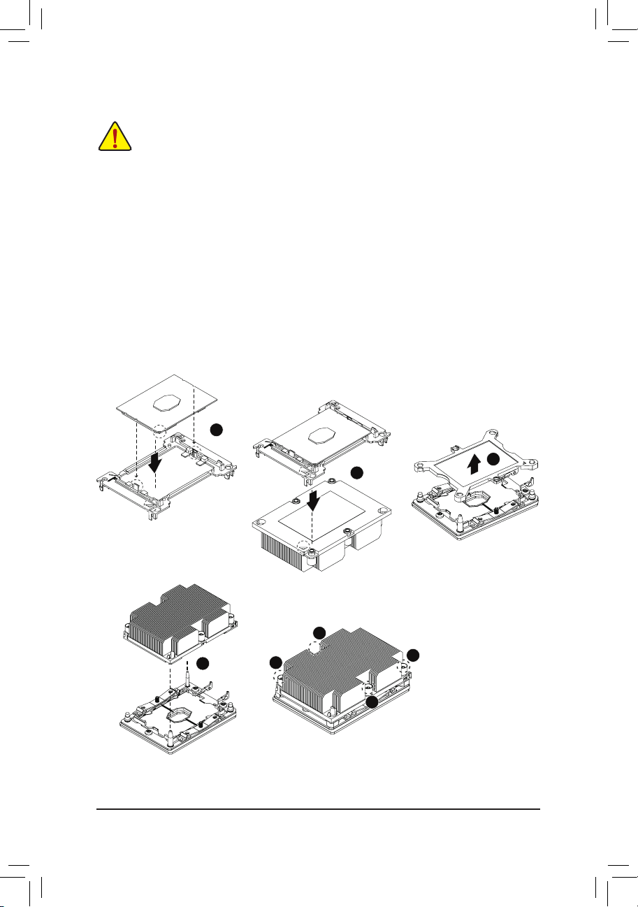
1-3 Installing the CPU
Read the following guidelines before you begin to install the CPU:
• Make sure that the motherboard supports the CPU.
• Always turn off the computer and unplug the power cord from the power outlet before installing the
CPU to prevent hardware damage.
• Locate the pin one of the CPU. The CPU cannot be inserted if oriented incorrectly. (Or you may
locate the notches on both sides of the CPU and alignment keys on the CPU socket.)
• Apply an even and thin layer of thermal grease on the surface of the CPU.
• Do not turn on the computer if the CPU cooler is not installed, otherwise overheating and damage
of the CPU may occur.
• Set the CPU host frequency in accordance with the CPU specications. It is not recommended
that the system bus frequency be set beyond hardware specications since it does not meet the
standard requirements for the peripherals. If you wish to set the frequency beyond the standard
specications, please do so according to your hardware specications including the CPU, graphics
card, memory, hard drive, etc.
Installing the CPU
Locate the alignment keys on the motherboard CPU socket and the notches on the CPU.
C
B
A
B
A
1
C
2
3
8
4
6
5
7
- 11 -
Page 12
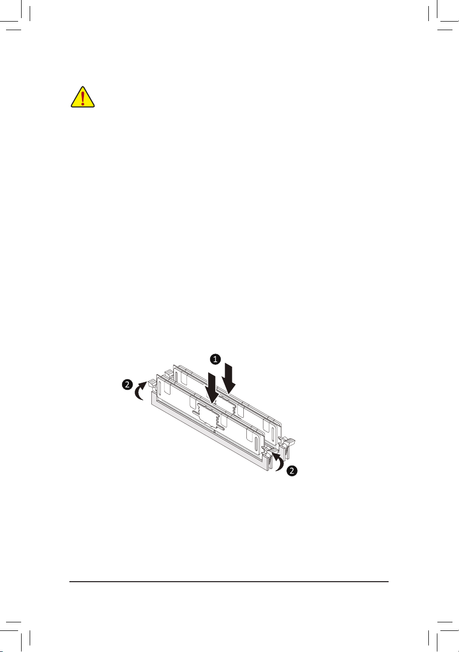
1-4 Installing the Memory
Read the following guidelines before you begin to install the memory:
• Make sure that the motherboard supports the memory. It is recommended that memory of the same
capacity, brand, speed, and chips be used.
(Go to GIGABYTE's website for the latest supported memory speeds and memory modules.)
• Always turn off the computer and unplug the power cord from the power outlet before installing the
memory to prevent hardware damage.
• Memory modules have a foolproof design. A memory module can be installed in only one direction.
If you are unable to insert the memory, switch the direction.
6ChannelMemoryConguration
This motherboard supports 6 Channel Technology. After the memory is installed, the BIOS will automatically
detect the specications and capacity of the memory.
The eight DDR4 memory sockets are divided into 6 channels as following:
Channel 1: DIMM-A1, DIMM-A2
Channel 2: DIMM-B1
Channel 3: DIMM-C1
Channel 4: DIMM-D1, DIMM-D2
Channel 5: DIMM-E1
Channel 6: DIMM-F1
Due to CPU limitations, read the following guidelines before installing the memory in 6 Channel mode.
1. 6 Channel mode cannot be enabled if only one memory module is installed.
2. It is recommended that memory of the same capacity, brand, speed, and chips be used.
Note: When installing the memory in Channel 1 or Channel 4, make sure to begin with DIMM-A1 or DIMM-D1,
or the system will not boot properly.
- 12 -
Page 13
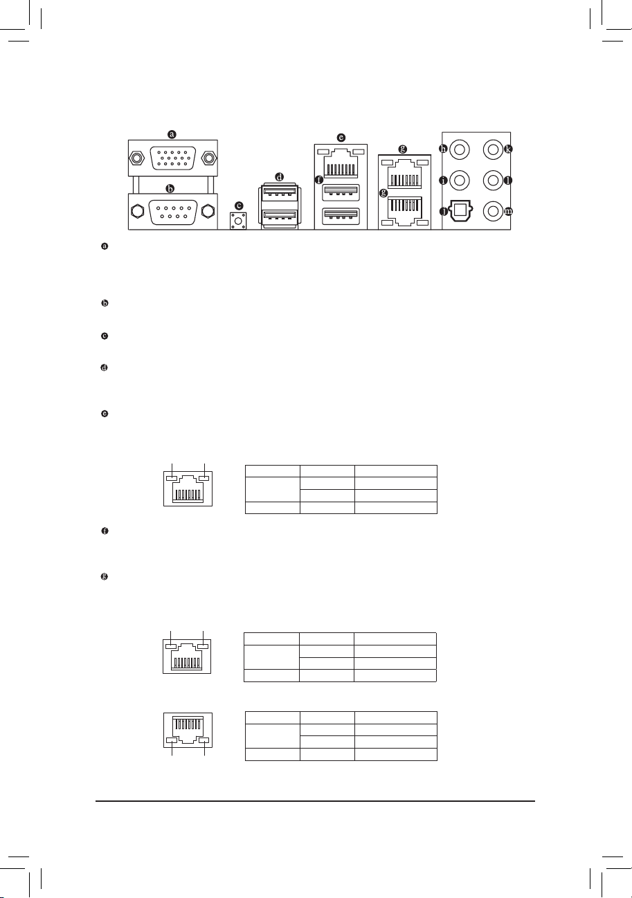
1-5 Back Panel Connectors
D-Sub Port
The D-Sub port supports a 15-pin D -Sub connector and supports a maximum resolution of 1920x1200@60 Hz
(the actual resolutions supported depend on the monitor being used). Connect a monitor that supports
D-Sub connection to this port.
Serial Port
Use the serial port to connect devices such as a mouse, modem or other peripherals.
UID Button
The UID button.
USB 3.1 Gen 2 Type-A Port (Red)
The USB 3.1 Gen 2 Type-A port supports the USB 3.1 Gen 2 specication and is compatible to the USB
3.1 Gen 1 and USB 2.0 specication. Use this port for USB devices.
IPMI Port (LAN1)
The Gigabit Ethernet LAN port provides Internet connection at up to 1 Gbps data rate. The following
describes the states of the LAN port LEDs.
Activity LEDLink LED
LAN Port
USB 3.1 Gen 1 Port
The USB 3.1 Gen 1 port supports the USB 3.1 Gen 1 specication and is compatible to the USB 2.0
specication. You can use this port for USB devices.
GbE LAN Port (LAN2)(LAN3)
The Gigabit Ethernet LAN port provides Internet connection at up to 1 Gbps data rate. The following
describes the states of the LAN port LEDs.
Link LEDActivity LED
LAN Port
LED State Description
Link (Left)
Activity (Right) Blinking Yellow Active
LED State Description
Link (Right)
Activity (Left) Blinking Yellow Active
Solid Green 100 Mbps data rate
Solid Amber 1 Gbps data rate
Solid Green 100 Mbps data rate
Solid Amber 1 Gbps data rate
LAN Port
LED State Description
Link (Right)
Activity LEDLink LED
Activity (Left) Blinking Yellow Active
Solid Green 100 Mbps data rate
Solid Amber 1 Gbps data rate
- 13 -
Page 14

Center/Subwoofer Speaker Out
Use this audio jack to connect center/subwoofer speakers in a 5.1/7.1-channel audio conguration.
Rear Speaker Out
This jack can be used to connect rear speakers in a 4/5.1/7.1-channel audio conguration.
Optical S/PDIF Out Connector
This connector provides digital audio out to an external audio system that supports digital optical audio.
Before using this feature, ensure that your audio system provides an optical digital audio in connector.
Line In
The line in jack. Use this audio jack for line in devices such as an optical drive, walkman, etc.
Line Out
The line out jack. Use this audio jack for a headphone or 2-channel speaker. This jack can be used to
connect front speakers in a 4/5.1/7.1-channel audio conguration.
Mic In
The Mic in jack.
• When removing the cable connected to a back panel connector, rst remove the cable from your
device and then remove it from the motherboard.
• When removing the cable, pull it straight out from the connector. Do not rock it side to side to
prevent an electrical short inside the cable connector.
- 14 -
Page 15
1-6 Internal Connectors
373739
123730
36
33
34
25
4
8
5
10
7
9
18
16
1415
6
29
32
12
28
28
1 BMC_VGA
2 BMC_WATCHD
3 Buzzer
4 COMB
5 SMB_IPMB
6 I_SGPIO1
7 I_SGPIO2
8 WOL
9 SMB
10 TPM
38
22
3
23
13 11 25 17 31 35 19 25 24 27 20
11 S_SGPIO
12 SATA_DOM0
13 SATA_DOM1
14 VRM_SCL
15 VRM_SDA
16 FUSB30
17 VROC
18 FUSB2
19 F_PANEL
20 PMBUS
21 UID
22 CLR_CMOS
23 CI
24 CPU_FAN1
25 SYS_FAN1~6
26 AT X
27 ATX8P
28 S-SATA0~1
29 I-SATA0~5
30 PCIEX4_M2
31 PCIEX2_M2
32 F_USB30C
33 F_AUDIO
34 THB_C
35 F_LED1
36 F_LED2
37 BMC_LED1
38 B AT
39 SMB_VMD
21
25
26
Read the following guidelines before connecting external devices:
• First make sure your devices are compliant with the connectors you wish to connect.
• Before installing the devices, be sure to turn off the devices and your computer. Unplug the power
cord from the power outlet to prevent damage to the devices.
• After installing the device and before turning on the computer, make sure the device cable has
been securely attached to the connector on the motherboard.
- 15 -
Page 16

1) BMC_VGA
1
2) BMC_WATCHD
1
3) Buzzer
Pin Denition
1-2 Enable (Default)
2-3 Disable
Pin Denition
1-2 Enable
2-3 Disable (Default)
4) COMB (Serial Port Header)
2101
9
Pin Denition Pin Denition
1 NDCD- 2 NSIN
3 NSOUT 4 NDTR-
5 GND 6 NDSR-
7 NRTS- 8 NCTS-
9 NRI- 10 -
- 16 -
Page 17

5) SMB_IPMB
1
6) I_SGPIO1 (For I-SATA0~2)
7) I_SGPIO2 (For I-SATA3~5)
Pin Denition
1 SMB_DATA
2 GND
3 SMB_CLK
4 NA
718
2
8) WOL (Wake On Lan)
1
9) SMB
1
Pin Denition Pin Denition
1 NA 2 -
3 SATA_DATA 4 GND
5 GND 6 SATA_LOAD
7 NA 8 SATA_CLK
Pin Denition
1 P5V_AUX
2 GND
3 WAKE_EN
Pin Denition
1 SMB_DATA
2 GND
3 SMB_CLK
- 17 -
Page 18

10) TPM (Trusted Platform Module/Port 80 Header)
2121
11
Pin Denition Pin Denition
1 LPC_IO0 2 P3V3
3 LPC_IO1 4 -
5 LPC_IO2 6 TPM_CLK
7 LPC_IO3 8 GND
9 LFRAME# 10 NA
11 SERIRQ 12 TPM_RST
11) S_SGPIO (For S-SATA0~1)
Pin Denition Pin Denition
718
2
1 NA 2 -
3 SATA_DATA 4 GND
5 GND 6 SATA_LOAD
7 NA 8 SATA_CLK
12) SATA_DOM0 (SATA DOM0 Power Header)
13) SATA_DOM1 (SATA DOM1 Power Header)
1
1
Pin Denition
1 P5V
2 GND
3 NA
14) VRM_SCL (For VRM SMB_CLK)
15) VRM_SDA (For VRM SMB_DATA)
1
1
Pin Denition
1-2 SMB to PCH
2-3 SMB to BMC
- 18 -
Page 19

16) FUSB30
Pin Denition Pin Denition
11
10
20
1
1 VBUS 11 D2+
2 SSRX1- 12 D2-
3 SSRX1+ 13 GND
4 GND 14 SSTX2+
5 SSTX1- 15 SSTX2-
6 SSTX1+ 16 GND
7 GND 17 SSRX2+
8 D1- 18 SSRX2-
9 D1+ 19 VBUS
10 NC 20 -
17) VROC (RAID Key for CPU NVMe SSD)
Pin Denition
1
1 GND
2 P3V3_AUX
3 GND
4 PCH RAID KEY
18) FUSB2
2
1
10
9
Pin Denition Pin Denition
1 Power (5V) 2 Power (5V)
3 USB DX- 4 USB DY-
5 USB DX+ 6 USB DY+
7 GND 8 GND
9 - 10 NC
- 19 -
Page 20

19) F_PANEL
Pin Denition Pin Denition
2 24
1 23
1 Power LED+ 2 5V Standby
3 - 4 ID LED+
5 Power LED- 6 ID LED-
7 HDD LED+ 8 System Status LED+
9 HDD LED1 10 System Status LED11 Power Button 12 LAN1 Active LED+
13 GND 14 LAN1 Link LED-
15 Reset Button 16 SMBus Data
17 GND 18 SMBus Clock
19 ID Button 20 Case Open
21 GND 22 LAN2 Active LED+
23 NMI Switch 24 LAN2 Link LED-
20) PMBUS (Power Supply I2C Connector)
Pin Denition
1 SMB_CLK
2 SMB_DATA
1
3 PSU_ALERT
4 GND
5 P3V3
21) UID
Pin Denition
1 UID_BTN
2 GND
3 GND
4 GND
- 20 -
Page 21

22) CLR_CMOS
1
23) CI
1
24) CPU_FAN1
1
Pin Denition
1-2 NA (Default)
2-3 Clear CMOS
Pin Denition
1 Intrusion Input
2 GND
Pin Denition
1 GND
2 P12V
3 FAN_TACH
4 FAN_PWM
25) SYS_FAN1~6
1
1
Pin Denition
1 GND
2 P12V
3 FAN_TACH
4 FAN_PWM
- 21 -
Page 22

26) ATX (2x12 Main Power Connector)
12 24
1 13
27) ATX8P (2x4, 12V Power Connector)
5
1
8
4
28) S-SATA0~1 (SATA 6Gb/s Connectors, Supported by the Intel® PCH)
29) I-SATA0~5 (SATA 6Gb/s Connectors, Supported by the Intel® SCU)
- 22 -
Page 23

30/31) PCIEX4_M2/PCIEX2_M2 (M.2 Socket 3 Connectors)
PCIEX4_M2 PCIEX2_M2
80
60
60
80
32) F_USB30C (USB Type-C™ Header with USB 3.1 Gen 1 Support)
Pin Denition Pin Denition
1
20
10
11
1 VBUS 11 VBUS
2 TX1+ 12 TX2+
3 TX1- 13 TX2-
4 GND 14 GND
5 RX1+ 15 RX2+
6 RX1- 16 RX2-
7 VBUS 17 GND
8 CC1 18 D-
9 NC 19 D+
10 NC 20 CC2
- 23 -
Page 24

33) F_ AUD I O
34) THB_C
910
12
5
1
Pin Denition
1 FORCE_POWER
2 SCI_EVENT
3 SLP_S3
4 SLP_S4
5 GND
35) F_LED1 (Onboard Power LED)
36) F_LED2(UIDLED,UnitIdentierLED)
F_LED1 F_LED2
State Description
Solid Red Standby
Solid Green Power On
State Description
Solid Blue Unit Identied
- 24 -
Page 25

37) BMC_LED1 (BMC Heartbeat LED)
State Description
Blinking
Yellow
BMC Normal
38) BAT
39) SMB_VMD (NVMe SMBUS Control Header)
910
12
Pin Denition
1 SMB_CPU1_NVME_CLK
2 SMB_CPU1_NVME_DATA
3 GND
4 GND
5 SMB_CPU2_NVME_CLK
6 SMB_CPU2_NVME_DATA
7 GND
8 -
9 SMB_PCH_NVME_CLK
10 SMB_PCH_NVME_DATA
- 25 -
Page 26

Chapter 2 BIOS Setup
BIOS (Basic Input and Output System) records hardware parameters of the system in the CMOS on the
motherboard. Its major functions include conducting the Power-On Self-Test (POST) during system startup,
saving system parameters and loading operating system, etc. BIOS includes a BIOS Setup program that allows
the user to modify basic system conguration settings or to activate certain system features.
When the power is turned off, the battery on the motherboard supplies the necessary power to the CMOS to
keep the conguration values in the CMOS.
To access the BIOS Setup program, press the <Delete> key during the POST when the power is turned on.
• Because BIOS ashing is potentially risky, if you do not encounter problems using the current version of BIOS,
it is recommended that you not ash the BIOS. To ash the BIOS, do it with caution. Inadequate BIOS ashing
may result in system malfunction.
• It is recommended that you not alter the default settings (unless you need to) to prevent system instability or
other unexpected results. Inadequately altering the settings may result in system's failure to boot. If this occurs,
try to clear the CMOS values and reset the board to default values. (Refer to the "Restore Defaults" section in
this chapter or introductions of the battery/clear CMOS jumper in Chapter 1 for how to clear the CMOS values.)
2-1 Startup Screen
The following startup Logo screen will appear when the computer boots.
- 26 -
Page 27

2-2 Main
Once you enter the BIOS Setup program, the Main Menu (as shown below) appears on the screen. Use arrow
keys to move among the items and press <Enter> to accept or enter a sub-menu.
Main Menu Help
The on-screen description of a highlighted setup option is displayed on the right of the Main Menu.
Submenu Help
While in a submenu, press <F1> to display a help screen (General Help) of function keys available for the menu.
Press <Esc> to exit the help screen. Help for each item is in the Item Help block on the right side of the submenu.
(Sample BIOS Version: SU8E0007)
• When the system is not stable as usual, select the Restore Defaults item to set your system to its
defaults.
• The BIOS Setup menus described in this chapter are for reference only and may differ by BIOS
version.
This section provides information on your motherboard model and BIOS version. You can also select the default
language used by the BIOS and manually set the system time.
& System Language
Selects the default language used by the BIOS.
& System Date
Sets the system date. The date format is week (read-only), month, date, and year. Use <Enter> to switch
between the Month, Date, and Year elds and use the <+> or <-> key to set the desired value.
& System Time
Sets the system time. The time format is hour, minute, and second. For example, 1 p.m. is 13:00:00. Use
<Enter> to switch between the Hour, Minute, and Second elds and use the <+> or <-> key to set the
desired value.
- 27 -
Page 28

2-3 Advanced
` iSCSIConguration
Congure the iSCSI parameters.
` Intel(R) Virtual RAID on CPU
This
sub-menu
allows the user to manage Intel(R) Virtual RAID on CPU.
` Intel(R) I210 Gigabit Network Connection (Dual_Lan)
This sub-menu provides information on LAN conguration and related conguration options.
` Intel(R) I210 Gigabit Network Connection (Dual_Lan)
This sub-menu provides information on LAN conguration and related conguration options.
` Trusted Computing
Enables or disables Trusted Platform Module (TPM).
` Serial Port Console Redirection
This section allows you to enable/disable serial port console redirection for remote server management
through a serial port.
` SIOConguration
& Serial Port 1/2
Enables or disables the onboard serial port.
- 28 -
Page 29

` PCI Subsystem Settings
& Above 4G Decoding
Enables or disables 64-bit capable devices to be decoded in above 4 GB address space (only if your system
supports 64-bit PCI decoding). Set to Enabled if more than one advanced graphics card are installed and
their drivers are not able to be launched when entering the operating system (because of the limited 4 GB
memory address space).
` NetworkStackConguration
& Network Stack
Disables or enables booting from the network to install a GPT format OS, such as installing the OS from
the Windows Deployment Services server.
& Ipv4 PXE Support
Enables or disables IPv4 PXE Support. This item is congurable only when Network Stack is enabled.
& Ipv4 HTTP Support
Enables or disables HTTP boot support for IPv4. This item is congurable only when Network Stack is
enabled.
& Ipv6 PXE Support
Enables or disables IPv6 PXE Support. This item is congurable only when Network Stack is enabled.
& Ipv6 HTTP Support
Enables or disables HTTP boot support for IPv6. This item is congurable only when Network Stack is
enabled.
& PXE boot wait time
Allows you to congure how long to wait before you can press <Esc> to abort the PXE boot. This item is
congurable only when Network Stack is enabled.
& Media detect count
Allows you to set the number of times to check the presence of media. This item is congurable only when
Network Stack is enabled.
` CSMConguration
& CSM Support
Enables or disables UEFI CSM (Compatibility Support Module) to support a legacy PC boot process.
Enabled Enables UEFI CSM.
Disabled Disables UEFI CSM and supports UEFI BIOS boot process only.
& GateA20 Active
Upon Request GA20 can be disabled using BIOS services.
Always GA20 cannot be disabled.
This option is useful when any RT code is executed above 1MB. This item is congurable only when CSM
Support is set to Enabled.
& Option ROM Message
Set display mode for Option ROM. Options available: Force BIOS, Keep Current.
This item is congurable only when CSM Support is set to Enabled.
& INT19 Trap Response
Congures BIOS reaction on INT19 trapping by Option ROM.
Immediate The system executes the trap right away.
Postponed The system executes the trap during legacy boot.
This item is congurable only when CSM Support is set to Enabled.
- 29 -
Page 30

& Bootoptionlter
Controls Legacy/UEFI ROMs priority.
UEFI and Legacy Disables option ROM.
Legacy only Enables legacy option ROM only.
UEFI only Enables UEFI option ROM only.
This item is congurable only when CSM Support is set to Enabled.
& Network
Allows you to select whether to enable the legacy option ROM for the LAN controller.
Legacy Enables legacy option ROM only.
UEFI Enables UEFI option ROM only.
This item is congurable only when CSM Support is set to Enabled.
& Storage
Allows you to select whether to enable the UEFI or legacy option ROM for the storage device controller.
Legacy Enables legacy option ROM only.
UEFI Enables UEFI option ROM only.
This item is congurable only when CSM Support is set to Enabled.
& Video
Allows you to select whether to enable the UEFI or Legacy option ROM for the graphics controller.
Legacy Enables legacy option ROM only.
UEFI Enables UEFI option ROM only.
This item is congurable only when CSM Support is set to Enabled.
& Other PCI devices
Allows you to select whether to enable the UEFI or Legacy option ROM for the PCI device controller other
than the LAN, storage device, and graphics controllers.
Legacy Enables legacy option ROM only.
UEFI Enables UEFI option ROM only.
This item is congurable only when CSM Support is set to Enabled.
` Thunderbolt(TM)Conguration
& TBT Root port Selector
Allows you to select Thunderbolt AIC location.
` USBConguration
& Legacy USB Support
Allows USB keyboard/mouse to be used in MS-DOS.
& USB Mass Storage Driver Support
Enables or disables support for USB storage devices.
- 30 -
Page 31

2-4 PlatformConguration
` PCHConguration
` PCH Devices
& PCH state after G3
Allows you to select S0 or S5 for ACPI state after a G3.
` PCHSATAConguration(I-SATA0~5Connectors)
& SATA Controller
Enables or disables the integrated SATA controllers.
& CongureSATAas
Enables or disables RAID for the SATA controllers integrated in the Chipset or congures the SATA controllers
to AHCI mode.
RAID Enables RAID for the SATA controller.
AHCI Congures the SATA controllers to AHCI mode. Advanced Host Controller
` SATA Mode options
& SATA HDD Unlock
Enables or disables hard drive password unlock in the OS.
& SATA Led locate
If enabled, LED/SGPIO hardware is attached.
Interface (AHCI) is an interface specication that allows the storage driver
to enable advanced Serial ATA features such as Native Command Queuing
and hot plug.
& Support Aggressive Link Power Management
Enables or disables the power saving feature, ALPM (Aggressive Link Power Management), for the Chipset
SATA controllers.
& Load EFI Driver for RAID
Allows you to select whether to load EFI driver in RAID mode. If disabled, loads legacy OPROM.
- 31 -
Page 32

& SATA Port 0/1/2/3/4/5/x2 M.2 SATA Port
Enables or disables each SATA port.
` PCHsSATAConguration
& sSATA Controller (S-SATA0~1 Connectors)
Enables or disables the integrated SATA controllers.
& ConguresSATAas
Enables or disables RAID for the SATA controllers integrated in the Chipset or congures the SATA controllers
to AHCI mode.
RAID Enables RAID for the SATA controller.
AHCI Congures the SATA controllers to AHCI mode. Advanced Host Controller
Interface (AHCI) is an interface specication that allows the storage driver
to enable advanced Serial ATA features such as Native Command Queuing
and hot plug.
` SATA Mode options
& SATA HDD Unlock
Enables or disables hard drive password unlock in the OS.
& SATA Led locate
If enabled, LED/SGPIO hardware is attached.
& Support Aggressive Link Power Management
Enables or disables the power saving feature, ALPM (Aggressive Link Power Management), for the Chipset
SATA controllers.
& Load EFI Driver for RAID
Allows you to select whether to load EFI driver in RAID mode. If disabled, loads legacy OPROM.
& sSATA Port 0/1
Enables or disables each SATA port.
` MiscellaneousConguration
& Active Video
Allows you to select the active video type. Options are Auto, Onboard Device, PCIE Device.
& Single Bit Error
Enables or disables Single Bit Error selection.
- 32 -
Page 33

2-5 SocketConguration
` ProcessorConguration
The sub-menu displays and provides options to change the processor settings.
& Hyper-Threading [ALL]
The Hyper Threading Technology allows a single processor to execute two or more separate threads
concurrently. When hyper-threading is enabled, multi-threaded software applications can execute their.
& VMX
Enables or Disables the Vanderpool Technology. This will take effect after rebooting the system.
& PPIN Control
Select Unlock/Enable to use the Protected-Processor Inventory Number (PPIN) in the system.
& Hardware Prefetcher
Select whether to enable the speculative prefetch unit of the processor.
& Adjacent Cache Prefetch
When enabled, cache lines are fetched in pairs. When disabled, only the required cache line is fetched.
& DCU Streamer Prefetcher
Prefetches the next L1 data line based upon multiple loads in same cache line.
& DCU IP Prefetcher
Prefetches the next L1 data line based upon sequential load history.
& LLC Prefetch
Enables or disables LLC prefetch on all threads.
& Extended APIC
Enables or disables APIC support.
& AES-NI
Enables or disables AES-NI support.
- 33 -
Page 34

` UPI Status
The sub-menu displays UPI status.
` MemoryConguration
The sub-menu displays and provides options to change the memory settings.
` Memory Topology
Displays memory topology with DIMM population information.
` MemoryRASConguration
Displays and provides option to change the memory RAS settings.
& Single Bit Error ECC Threshold
Correctable Error Threshold (1-7fff) used for sparing, tagging, and leaky bucket.
` IIOConguration
The sub-menu displays and provides options to change the IIO settings.
` Socket0Conguration
Press [Enter] for conguration of advanced items.
` IIOGeneralConguration
The sub-menu provides options enable or disable the IIO IOAPIC Stacks 0~5.
` Intel® VT for Directed I/O (VT-d)
Enables or disables Intel® Virtualization Technology for Directed I/O.
` Intel® VMD technology
Enables or disables Intel® Volume Management Device (Intel® VMD) technology.
` AdvancedPowerManagementConguration
The sub-menu displays and provides options to change the power management settings.
& Turbo Mode
When this item is enabled, the processor will automatically ramp up the clock speed of 1-2 of its
processing cores to improve its performance. When this item is disabled, the processor will not
overclock any of its core.
` CPU C State Control
& Autonomous Core C-State
Enables or Disables Autonomous Core C-State Control.
& CPU C6 Report
Allows you to determine whether to let the CPU enter C6 mode in system halt state. When enabled, the
CPU core frequency and voltage will be reduced during system halt. Auto lets the BIOS automatically
congure this setting.
& Enhanced Halt State (C1E)
Enables or disables Intel® CPU Enhanced Halt (C1E) function, a CPU power-saving function in system halt
state.
When enabled, the CPU core frequency and voltage will be reduced during system halt state to
decrease power consumption.
& OS ACPI Cx
Reports CPU C3/C6 to OS ACPI C2 or ACPI C3.
` Package C State Control
& Package C State
Congures the state for the C-State package limit. Options are C0/C1 state, C2 state, C6(non Retention)
state, C6(Retention) state, No Limit, Auto.
- 34 -
Page 35

2-6 Server Mgmt
& BMC Support
Enables or disables interfaces to communicate with BMC.
& Wait For BMC
Allows you to determine whether to wait for BMC response for specied time out. In PILOTII, BMC starts
at the same time when BIOS starts during AC power ON. It takes around 30 seconds to initialize Host to
BMC interfaces.
` System Event Log
Press [Enter] to change the SEL event log conguration.
` Bmc self test log
Logs the report returned by BMC self test command.
` View FRU information
Press [Enter] to view FRU information.
` BMCnetworkconguration
Press [Enter] to congure BMC network parameters.
` View System Event Log
Press [Enter] to view the system event log records.
- 35 -
Page 36

2-7 Security
& Administrator Password
Allows you to congure an administrator password. Press <Enter> on this item, type the password, and
then press <Enter>. You will be requested to conrm the password. Type the password again and press
<Enter>. You must enter the administrator password (or user password) at system startup and when entering
BIOS Setup. Differing from the user password, the administrator password allows you to make changes to
all BIOS settings.
& User Password
Allows you to congure a user password. Press <Enter> on this item, type the password, and then press
<Enter>. You will be requested to conrm the password. Type the password again and press <Enter>.
You must enter the administrator password (or user password) at system startup and when entering BIOS
Setup. However, the user password only allows you to make changes to certain BIOS settings but not all.
To cancel the password, press <Enter> on the password item and when requested for the password, enter
the correct one rst. When prompted for a new password, press <Enter> without entering any password.
Press <Enter> again when prompted to conrm.
NOTE: Before setting the User Password, be sure to set the Administrator Password rst.
- 36 -
Page 37

2-8 Boot
& Bootup NumLock State
Enables or disables Numlock feature on the numeric keypad of the keyboard after the POST.
& Quiet Boot
Allows you to determine whether to display the GIGABYTE Logo at system startup.
& Boot mode select
Selects the boot mode. Options are LEGACY/UEFI.
& Boot Option #1/2/3/4/5/6/7/8/9
Species the boot order for a specic device type, such as hard drives, optical drives, oppy disk drives,
and devices that support Boot from LAN function, etc. Press <Enter> on this item to enter the submenu that
presents the devices of the same type that are connected. This item is present only if at least one device
for this type is installed.
- 37 -
Page 38

2-9 Save & Exit
& Save Changes and Exit
Press <Enter> on this item and select Yes. This saves the changes to the CMOS and exits the BIOS Setup
program. Select No or press <Esc> to return to the BIOS Setup Main Menu.
& Discard Changes and Exit
Press <Enter> on this item and select Yes. This exits the BIOS Setup without saving the changes made
in BIOS Setup to the CMOS. Select No or press <Esc> to return to the BIOS Setup Main Menu.
& Save Changes and Reset
Press <Enter> on this item and select Yes to save the changes to the CMOS. Select No or press <Esc>
to return to the BIOS Setup Main Menu. Reboot the system after saving the changes.
& Discard Changes and Reset
Press <Enter> on this item and select Yes to cancel the BIOS changes. Select No or press <Esc> to return
to the BIOS Setup Main Menu. Reboot the system without saving any changes.
& Save Changes
Press <Enter> on this item and select Yes to save the changes to the CMOS. Select No or press <Esc>
to return to the BIOS Setup Main Menu.
& Discard Changes
Press <Enter> on this item and select Yes to cancel the BIOS changes. Select No or press <Esc> to return
to the BIOS Setup Main Menu.
& Restore Defaults
Press <Enter> on this item and select Yes to load the BIOS factory default settings. The BIOS defaults
settings help the system to operate in optimum state. Always load the Optimized defaults after updating
the BIOS or after clearing the CMOS values.
& Save as User Defaults
Save to current BIOS settings as user-dened default settings.
& Restore User Defaults
Load the user-dene default settings for all BIOS options.
& Boot Override
Allows you to select a device to boot immediately. Press <Enter> on the device you select and select Yes
to conrm. Your system will restart automatically and boot from that device.
- 38 -
Page 39

Chapter 3 Application
Dashboard
This page shows the summary monitoring information of the board.
Dashboard- Event Log
This page displays the list of events incurred by the different sensors on this device. Click on a record to see the
details of that entry. With your cursor, hover over the graph to view the number of events by date. You can also
sele ct bet ween BMC or Client Time zone. You can use the dat e ra nge, sen sor typ e, or sensor nam e l te r opti ons
to view those specic events. Click Clear Event Logs option to delete all existing records for all sensors. Click
Download Event Logs option to download the logs in a text le format.
- 39 -
Page 40

Dashboard- Audit Log
This page displays audit events for this device (if congured).
Note: For conguration, go to "Settings/Log Settings/Advanced Log Settings."
Sensor
On this page, details for all the available sensors e.g. Name, Type, Status, Current Reading and Behavior are
displayed Th e sensor readings are avail able for Temperature, Fan, Watchdo g and Voltage Sensors as wel l as for
suppor ted Discrete Senso rs. This page will refr esh automatically w ith the latest data retr ieved from the databa se.
Please note that there may be some delay in retrieving this live data. Sensors are organized by their Type and
State (Critical, Discrete, Normal and Disabled).
Sensor Details
Click on any sensor to view more information about it. For each sensor, thresholds (if supported) and graphical
representation of all associated events (read-only) are shown. If you select a sensor from the Normal Sensors
sections, a Live Widget is also displayed showing its behavior over time.
- 40 -
Page 41

FRU Information
This page displays Basic Information, Chassis Information, Board Information, and Product Information for the
BMC's FRU devices.
FRU Device ID
Select a FRU Device ID from the drop-down list to view the details of that device.
FRU Device Name
The device name of the selected FRU will be displayed.
System Information
The BIOS, CPU and DIMM Device information list.
- 41 -
Page 42

Logs & Reports- IPMI Event Log
This page displays the list of events incurred by the different sensors on this device. Click on a record to see the
details of that entry. With your cursor, hover over the graph to view the number of events by date. You can also
sele ct bet ween BMC or Client Time zone. You can use the dat e ra nge, sen sor typ e, or sensor nam e l te r opti ons
to view those specic events. Click Clear Event Logs option to delete all existing records for all sensors. Click
Download Event Logs option to download the logs in a text le format.
Logs & Reports- System Log
This page displays logs of system events for this device (if the options have been congured).
Note: Logs must be congured under "Settings/Log Settings/Advanced Log Settings" to display any entries.
Filtering options are also available for this and all logs in this section.
- 42 -
Page 43

Logs & Reports- Audit Log
This page displays audit events for this device (if congured).
Note: For conguration, go to "Settings/Log Settings/Advanced Log Settings."
Logs & Reports- Video Log
This page displays available recorded video les (if the options have been congured).
Note: For conguration, go to "Settings/Video Recording/Auto Video Settings/Video Trigger Settings."
- 43 -
Page 44

Settings
This page allows you to congure BMC options. The options are: Captured BSOD, Date & Time, External
User Services, KVM Mouse Setting, Log Settings, Media Redirection Settings, Network Settings, PAM Order
Settings, Platform Event Filter, Services, SMTP Settings, SSL Settings, System Firewall, User Management,
and Video Recording.
Remote Control
On this page, you can remote control your host system on BIOS Setup or Operating System.
- 44 -
Page 45

Remote Control- Example 1
This page shows the BIOS Setup settings.
Remote Control- Example 2
This page shows the operating system settings.
- 45 -
Page 46

Image Redirection
The displayed table shows remote images available to the BMC. You can start redirection or clear the images
from here. Up to 4 images can be added for each image type, depending on your conguration.
Power Control
On this page, you can remote control the power of your host system.
- 46 -
Page 47

Maintenance
This page allows you to congure BMC options. The options are Backup Conguration, BMC Recovery, Firmware
Image Location, Firmware Information, Firmware Update, Preserve Conguration, Restore Conguration, Restore
Factory Defaults, and System Administrator.
- 47 -
Page 48

Regulatory Statements
Regulatory Notices
This document must not be copied without our written permission, and the contents there of must not be imparted to a
third party nor be used for any unauthorized purpose.
Contravention will be prosecuted. We believe that the information contained herein was accurate in all respects at the
time of printing. GIGABYTE cannot, however, assume any responsibility for errors or omissions in this text. Also note
that the information in this document is subject to change without notice and should not be construed as a commitment
by GIGABYTE.
Our Commitment to Preserving the Environment
In addition to high-efciency performance, all GIGABYTE motherboards fulll European Union regulations for RoHS
(Restriction of Certain Hazardous Substances in Electrical and Electronic Equipment) and WEEE (Waste Electrical and
Electronic Equipment) environmental directives, as well as most major worldwide safety requirements. To prevent releases
of harmful substances into the environment and to maximize the use of our natural resources, GIGABYTE provides the
following information on how you can responsibly recycle or reuse most of the materials in your "end of life" product.
Restriction of Hazardous Substances (RoHS) Directive Statement
GIGABYTE products have not intended to add and safe from hazardous substances (Cd, Pb, Hg, Cr+6, PBDE and
PBB). The parts and components have been carefully selected to meet RoHS requirement. Moreover, we at GIGABYTE
are continuing our efforts to develop products that do not use internationally banned toxic chemicals.
Waste Electrical & Electronic Equipment (WEEE) Directive Statement
GIGABYTE will fulll the national laws as interpreted from the 2002/96/EC WEEE (Waste Electrical and Electronic
Equipment) directive. The WEEE Directive species the treatment, collection, recycling and disposal of electric and
electronic devices and their components. Under the Directive, used equipment must be marked, collected separately,
and disposed of properly.
WEEE Symbol Statement
that it is recycled in a manner that protects human health and the environment. For more information about where you
can drop off your waste equipment for recycling, please contact your local government ofce, your household waste
disposal service or where you purchased the product for details of environmentally safe recycling.
Finally, we suggest that you practice other environmentally friendly actions by understanding and using the energy-saving
features of this product (where applicable), recycling the inner and outer packaging (including shipping containers) this
product was delivered in, and by disposing of or recycling used batteries properly. With your help, we can reduce the
amount of natural resources needed to produce electrical and electronic equipment, minimize the use of landlls for
the disposal of "end of life" products, and generally improve our quality of life by ensuring that potentially hazardous
substances are not released into the environment and are disposed of properly.
Battery Information
European Union—Disposal and recycling information
GIGABYTE Recycling Program (available in some regions)
The symbol shown below is on the product or on its packaging, which indicates that this product must
not be disposed of with other waste. Instead, the device should be taken to the waste collection centers
for activation of the treatment, collection, recycling and disposal procedure. The separate collection and
recycling of your waste equipment at the time of disposal will help to conserve natural resources and ensure
When your electrical or electronic equipment is no longer useful to you, "take it back" to your local or regional waste
collection administration for recycling.
If you need further assistance in recycling, reusing in your "end of life" product, you may contact us at the Customer
Care number listed in your product's user's manual and we will be glad to help you with your effort.
This symbol indicates that this product and/or battery should not be disposed of with household waste. You must use
the public collection system to return, recycle, or treat them in compliance with the local regulations.
- 48 -
Page 49

Contact Us
GIGA-BYTE TECHNOLOGY CO., LTD.
Address: No.6, Baoqiang Rd., Xindian Dist., New Taipei City 231, Taiwan
TEL: +886-2-8912-4000, FAX: +886 -2-8912-4005
Tech. and Non-Tech. Support (Sales/Marketing) : https://esupport.gigabyte.com
WEB address (English): https://www.gigabyte.com
WEB address (Chinese): https://www.gigabyte.com/tw
• GIGABYTE eSupport
To submit a technical or non-technical (Sales/Marketing) question, please link to:
https://esupport.gigabyte.com
- 49 -
 Loading...