

Page 1

When you installing AGP card, please make sure the following
notice is fully understood and practiced. If your AGP card has
"AGP 4X/8X (1.5V) notch"(show below), please make sure your
AGP card is AGP 4X/8X (1.5V).
AGP 4X/8X notch
Caution: AGP 2X card is not supported by Intel® 845(GE/PE) / 845(E/
G) / 850(E) / E7205 / 865(G/PE/P) / 875P. You might experience system
unable to boot up normally. Please insert an AGP 4X/8X card.
Example 1: Diamond Vipper V770 golden finger is compatible with 2X/4X
mode AGP slot. It can be switched between AGP 2X(3.3V) or 4X(1.5V)
mode by adjusting the jumper. The factory default for this card is
2X(3.3V). The GA-8IPE775 Series (or any AGP 4X/8X only)
motherboards might not function properly, if you install this card without
switching the jumper to 4X(1.5V) mode in it.
Example 2: Some ATi Rage 128 Pro graphics cards made by "Power Color",
the graphics card manufacturer & some SiS 305 cards, their golden finger
is compatible with 2X(3.3V)/4X(1.5V) mode AGP slot, but they support 2X
(3.3V) only. The GA-8IPE775 Series (or any AGP 4X/8X only)
motherboards might not function properly, If you install this card in it.
Note : Although Gigabyte's AG32S(G) graphics card is based on ATi Rage
128 Pro chip, the design of AG32S(G) is compliance with AGP 4X(1.5V)
specification. Therefore, AG32S(G) will work fine with Intel® 845(GE/PE) /
845(E/G) / 850(E) / E7205 / 865(G/PE/P) / 875P based motherboards.
Before you install PCI cards, please remove the Dual BIOS label from
PCI slots if there is one.
Page 2

00
0 The author assumes no responsibility for any errors
00
or omissions that may appear in this document nor
does the author make a commitment to update the
information contained herein.
00
0 Third-party brands and names are the property of
00
their respective owners.
00
0 Please do not remove any labels on motherboard, this
00
may void the warranty of this motherboard.
00
0 Due to rapid change in technology, some of the
00
specifications might be out of date before publication
of this booklet.
Page 3

GA-8IPE775 Pro/GA-8IPE775-G/GA-8IPE775
Mother Board
May 14, 2004
Page 4

DECLARATION OF CONFORMITY
Per FCC Part 2 Section 2.1077(a)
Responsible Party Name:
Address:
Phone/Fax No:
hereby declares that the product
Product Name:
Model Number:
Conforms to the following specifications:
FCC Part 15, Subpart B, Section 15.107(a) and Section 15.109
(a),Class B Digital Device
Supplementary Information:
This device complies with part 15 of the FCC Rules. Operation is
subject to the following two conditions: (1) This device may not
cause harmful and (2) this device must accept any inference received,
including that may cause undesired operation.
Representative Person’s Name:
Signature:
G.B.T. INC. (U.S.A.)
17358 Railroad Street
City of Industry, CA 91748
(818) 854-9338/ (818) 854-9339
Motherboard
GA-8IPE775 Pro/GA-8IPE775-G
/GA-8IPE775
ERIC LU
Eric Lu
Date:
May 14, 2004
Page 5

GA-8IPE775 Series
Intel® Pentium® 4 Socket 775 Processor Motherboard
USER'S MANUAL
Pentium® 4 Processor Motherboard
Rev. 1004
12ME-8IPE775-1004
Page 6

Table of Content
English
Warning ................................................................................................... 4
Chapter 1 Introduction .............................................................................5
Chapter 2 Hardware Installation Process ............................................. 11
Chapter 3 BIOS Setup .......................................................................... 31
Features Summary ...................................................................................... 5
GA-8IPE775 Series Motherboard Layout .................................................... 7
Block Diagram ............................................................................................. 8
Step 1: Install the Central Processing Unit (CPU)..................................... 12
Step 1-1: Installation of the CPU .................................................................................... 12
Step 1-2: Installation of the Heatsink .............................................................................. 13
Step 2: Installation of Memory ................................................................... 13
Step 3: Install expansion cards ................................................................. 16
Step 4: Install I/O Peripherals Cables ....................................................... 17
Step 4-1: I/O Back Panel Introduction ............................................................................ 17
Step 4-2: Connectors Introduction .................................................................................. 19
The Main Menu (For example: BIOS Ver. : 8IPE775 Pro.D4) .................. 32
Standard CMOS Features......................................................................... 34
Advanced BIOS Features .......................................................................... 37
Integrated Peripherals .............................................................................. 39
Power Management Setup ....................................................................... 43
GA-8IPE775 Series Motherboard
- 2 -
Page 7

PnP/PCI Configurations ............................................................................. 45
PC Health Status........................................................................................ 46
Frequency/Voltage Control ........................................................................ 48
Load Fail-Safe Defaults ............................................................................. 50
Load Optimized Defaults ........................................................................... 50
Set Supervisor/User Password .................................................................. 51
Save & Exit Setup ....................................................................................... 52
Exit Without Saving ................................................................................... 52
Chapter 4 Technical Reference ............................................................ 53
Flash BIOS Method Introduction............................................................... 53
2- / 4- / 6- / 8- Channel Audio Function Introduction ................................. 67
Jack-Sensing and UAJ Introduction .......................................................... 73
Xpress Recovery2 Introduction ................................................................. 75
English
Chapter 5 Appendix .............................................................................. 79
- 3 -
Table of Content
Page 8

Warning
English
Computer motherboards and expansion cards contain very delicate Integrated Circuit (IC) chips. To
protect them against damage from static electricity, you should follow some precautions whenever you
work on your computer.
Installing the motherboard to the chassis...
are no slots to attach the spacers, do not become alarmed you can still attach the spacers to the
mounting holes. Just cut the bottom portion of the spacers (the spacer may be a little hard to cut off, so
be careful of your hands). In this way you can still attach the motherboard to the base without worrying
about short circuits. Sometimes you may need to use the plastic springs to isolate the screw from the
motherboard PCB surface, because the circuit wire may be near by the hole. Be careful, don't let the
screw contact any printed circuit write or parts on the PCB that are near the fixing hole, otherwise it
may damage the board or cause board malfunctioning.
1. Unplug your computer when working on the inside.
2. Use a grounded wrist strap before handling computer components. If you do not have one,
touch both of your hands to a safely grounded object or to a metal object, such as the power
supply case.
3. Hold components by the edges and try not touch the IC chips, leads or connectors, or other
components.
4. Place components on a grounded antistatic pad or on the bag that came with the components
whenever the components are separated from the system.
5. Ensure that the ATX power supply is switched off before you plug in or remove the ATX power
connector on the motherboard.
If the motherboard has mounting holes, but they don't line up with the holes on the base and there
GA-8IPE775 Series Motherboard
- 4 -
Page 9

Chapter 1 Introduction
Features Summary
CPU y Supports the latest Intel® Pentium® 4 Socket 775 CPU
y Supports 533/800MHz FSB
y L2 cache varies with CPU
Motherboard y GA-8IPE775 Series Motherboard:
GA-8IPE775 Pro/GA-8IPE775-G/GA-8IPE775
Chipset y North Bridge: Intel® 865PE
y South Bridge: Intel
Memory y 4 184-pin DDR DIMM sockets
y Supports Dual channel DDR400/DDR333/DDR266 DIMM
y Supports 128MB/256MB/512MB/1GB unbuffered DRAM
y Supports up to 4GB DRAM (Max)
Slots y 1 AGP slot supports 8X/4X(1.5V) mode
y 5 PCI slots
On-Board IDE y 2 IDE bus master (UDMA33/ATA66/ATA100) IDE ports for up to
4 ATAPI devices
y Can connect up to 4 IDE devices
On-Board Floppy y 1 Floppy port supports 2 FDD with 360K, 720K,1.2M, 1.44M and
2.88M bytes
On-Board Peripherals y 1 Parallel port supports Normal/EPP/ECP mode
y 2 Serial ports (COMA & COMB)
y 8 USB 2.0/1.1 ports (4 x Rear, 4 x Front by cable)
y 1 IrDA connector for IR/CIR
y 3 IEEE1394 (by cable)
y 1 Front Audio connector
y 1 PS/2 keyboard port
y 1 PS/2 mouse port
®
ICH5
(Note 1)
English
to be continued......
Due to chipset (Intel 865PE) architecture limitation, a FSB 800 Pentium 4
processor will support DDR400/DDR333/DDR266 memory module. A FSB 533 Pentium 4
processor will support DDR333 and DDR266 memory module.
(Note 1) Due to standard PC architecture, a certain amount of memory is reserved for system
usage and therefore the actual memory size is less than the stated amount.
For example, 4 GB of memory size will instead be shown as 3.xxGB memory
during system startup.
Only for GA-8IPE775 Pro.
- 5 -
Introduction
Page 10

On-Board LAN y Build in Marvell 8001 Chipset (10/100/1000 Mbit)
On-Board IEEE1394
English
On-Board Sound y ALC850 CODEC (UAJ)
Serial ATA y 2 Serial ATA connectors (SATA0/SATA1)
Hardware Monitor y CPU/Power /System Fan Revolution detect
I/O Control y IT8712
PS/2 Connector y PS/2 Keyboard interface and PS/2 Mouse interface
BIOS y Licensed AWARD BIOS
Additional Features y Supports EasyTune
Overclocking y Over Voltage (DDR/AGP/CPU) by BIOS
Form Factor y ATX size form factor; 30.5cm x 24.4cm
y 1 RJ45 port
y Ti TSB43AB23
y Supports Jack Sensing function
y Supports 2 / 4 / 6 / 8 channel audio
y Supports Line In / Line Out / MIC connection
y Surround Back Speaker (use of Surround-Kit to select)
y SPDIF In / Out
y CD In / Game connector
y Controlled by ICH5
y CPU/Power
y CPU Overheat Warning
y System Voltage Detect
y Supports Dual BIOS /Q-Flash
y Supports @BIOS
y Supports CPU Smart Fan Control function
y Over Clock (DDR/AGP/CPU/PCI) by BIOS
/System Fan Fail Warning
Only for GA-8IPE775 Pro.
Only for GA-8IPE775-G.
GA-8IPE775 Series Motherboard
- 6 -
Page 11

GA-8IPE775 Series Motherboard Layout
English
KB_MS
COMA
COMB
R_USB
USB
AUDIO
F_AUDIO
CODEC
LPT
LAN
CD_IN
SUR_CEN
IT8712
ATX_12V
CPU_FAN
Marvell
8001
Intel® 865PE
DUAL CHANNEL DDR
SATA
CI
IR_CIR
GAME
P4 Titan
SPDIF_IO
SOCKET 775
PCI4
PCI5
PCI1
PCI2
PCI3
MAIN
BIOS
BACKUP
BIOS
GA-8IPE775 (Pro/-G)
AGP
BAT
TSB43AB23
F2_1394
DDR1
DDR2
ICH5
CLR_CMOS
F1_1394
DDR4
DDR3
INFO_LINK
F_USB2
ATX
IDE2
PWR_FAN
F_USB1
FDD
IDE1
SATA1
SATA0
SYS_FAN
F_PANEL
PWR_LED
Only for GA-8IPE775 Pro.
Only for GA-8IPE775-G.
- 7 -
Introduction
Page 12

Block Diagram
English
PCICLK
(33MHz)
AGPCLK
(66MHz)
5 PCI
AGP 8X/4X
IEEE 1394
TSB43AB23
RJ45
Marvell 8001
AC97 Link
AC97
CODEC
MIC
LINE-IN
8 USB
(2.0/1.1)
Ports
LINE-OUT
LGA 775
Processor
System Bus
Intel 865PE
ICH5
800MHz
266/333/400MHz
48 MHz
LPC BUS
24 MHz
ATA33/66/100
IDE Channels
Serial ATA
Channels
CPUCLK+/- (200MHz)
ZCLK (66MHz)
HCLK+/- (200MHz)
66MHz
33 MHz
14.318 MHz
Dual BIOS
IT8712
33 MHz
DDR
Game Port
Floppy
LPT Port
PS/2
KB/Mouse
COM
Ports
PCICLK (33MHz)
USBCLK (48MHz)
14.318 MHz
24 MHz
Only for GA-8IPE775 Pro.
Only for GA-8IPE775-G.
GA-8IPE775 Series Motherboard
33 MHz
CLK GEN
- 8 -
ZCLK (66MHz)
CPUCLK+/- (200MHz)
AGPCLK (66MHz)
HCLK+/- (200MHz)
ICH3V66 (66MHz)
Page 13

English
- 9 -
Introduction
Page 14

English
GA-8IPE775 Series Motherboard
- 10 -
Page 15

Chapter 2 Hardware Installation Process
To set up your computer, you must complete the following steps:
Step 1- Install the Central Processing Unit (CPU)
Step 2- Install memory modules
Step 3- Install expansion cards
Step 4- Install I/O Peripherals Cables
English
Step 4
Step 1
Step 4
Step 3
Congratulations! You have accomplished the hardware installation!
Turn on the power supply or connect the power cable to the power outlet. Continue with
the BIOS/software installation.
Step 2
Step 4
- 11 -
Hardware Installation Process
Page 16

Step 1: Install the Central Processing Unit (CPU)
English
Step 1-1: Installation of the CPU
Before installing the CPU, please comply with the following conditions:
1. Please make sure that the motherboard supports the CPU.
2. Please take note of the one indented corner of the CPU. If you install the CPU in the wrong
direction, the CPU will not insert properly. If this occurs, please change the insert direction
of the CPU.
3. Please add an even layer of heat sink paste between the CPU and heatsink.
4. Please make sure the heatsink is installed on the CPU prior to system use, otherwise
overheating and permanent damage of the CPU may occur.
5. Please set the CPU host frequency in accordance with the processor specifications. It is
not recommended that the system bus frequency be set beyond hardware specifications
since it does not meet the required standards for the peripherals. If you wish to set the
frequency beyond the proper specifications, please do so according to your hardware
specifications including the CPU, graphics card, memory, hard drive, etc.
HT functionality requirement content :
Enabling the functionality of Hyper-Threading Technology for your computer system requires
all of the following platform components:
- CPU: An Intel® Pentium 4 Processor with HT Technology
- Chipset: An Intel® Chipset that supports HT Technology
- BIOS: A BIOS that supports HT Technology and has it enabled
- OS: An operation system that has optimizations for HT Technology
Metal Lever
Fig. 1
Gently lift the metal
lever located on the
CPU socket to the
upright position.
Fig. 3
Notice the small gold
colored triangle located
on the edge of the CPU
socket. Align the
indented corner of the
CPU with the triangle
and gently insert the
CPU into position.
Fig. 2
Remove the plastic
covering on the CPU
socket.
Fig. 4
Once the CPU is
properly inserted,
please replace the
plastic covering and
push the metal lever
back into its original
position.
- 12 -GA-8IPE775 Series Motherboard
Page 17

Step 1-2: Installation of the Heatsink
English
Fig.1
Please apply an even
layer of heatsink paste
on the surface of the
installed CPU.
(for detailed installation instructions, please refer to
the heat sink installation section of the user manual)
Fig. 3
Please attach the power connector of the heatsink to the CPU fan header
located on the motherboard. Installation is complete.
The heatsink may adhere to the CPU as a result of hardening of the heatsink paste. If the heatsink
is removed when this occurs, the CPU may become pulled from its socket with the metal lever
still in its locked position and result in damage to the processor pins. To prevent such an
occurrence, it is suggested that either thermal tape rather than heat sink paste be used for heat
dissipation or using extreme care when removing the heatsink.
Fig. 2
Place the heatsink atop
the CPU and then
secure each of the four
heatsink clips by
pressing downwards.
Step 2: Installation of Memory
Before installing the memory modules, please comply with the following conditions:
1. Please make sure that the memory used is supported by the motherboard. It is
recommended that memory of similar capacity, specifications and brand be used.
2. Before installing or removing memory modules, please make sure that the computer
power is switched off to prevent hardware damage.
3. Memory modules have a foolproof insertion design. A memory module can be installed in
only one direction. If you are unable to insert the module, please switch the direction.
- 13 -
Hardware Installation Process
Page 18

The motherboard supports DDR memory modules, whereby BIOS will automatically detect memory
capacity and specifications. Memory modules are designed so that they can be inserted only in one
direction. The memory capacity used can differ with each slot.
English
Notch
DDR
1. The DIMM socket has a notch, so the DIMM memory
module can only fit in one direction.
2. Insert the DIMM memory module vertically into the DIMM
socket. Then push it down.
3. Close the plastic clip at both edges of the DIMM sockets to
lock the DIMM module.
Reverse the installation steps when you wish to remove
the DIMM module.
DDR Introduction
Established on the existing SDRAM infrastructure, DDR (Double Data Rate) memory is a high
performance and cost-effective solution that allows easy adoption for memory vendors, OEMs, and
system integrators.
DDR memory is a great evolutionary solution for the PC industry that builds on the existing SDRAM
architecture, yet make the awesome advances in solving the system performance bottleneck by doubling
the memory bandwidth. Nowadays, with the highest bandwidth of 3.2GB/s of DDR400 memory and
complete line of DDR400/333/266/200 memory solutions, DDR memory is the best choice for building high
performance and low latency DRAM subsystem that are suitable for servers, workstations, and full range
of desktop PCs.
- 14 -GA-8IPE775 Series Motherboard
Page 19

GA-8IPE775 Series supports the Dual Channel Technology. After operating the Dual Channel Technology,
the bandwidth of Memory Bus will add double up to 6.4GB/s.
GA-8IPE775 Series includes 4 DIMM sockets, and each Channel has two DIMM sockets as following:
Channel A : DIMM 1, DIMM 2
Channel B : DIMM 3, DIMM 4
If you want to operate the Dual Channel Technology, please note the following explanations due
to the limitation of Intel® chipset specifications.
1. Only one DDR memory module is installed: The Dual Channel Technology can't operate
when only one DDR memory module is installed.
2. Two DDR memory modules are installed (the same memory size and type): The Dual
Channel Technology will operate when two memory modules are inserted individually into
Channel A and B. If you install two memory modules in the same channel, the Dual Channel
Technology will not operate.
3. Three DDR memory modules are installed: Please note that The Dual Channel
Technology will not operate when three DDR memory modules are installed; part of
them will not be detected.
4. Four DDR memory modules are installed: If you install four memory modules at the same
time, the Dual Channel Technology will operate only when those modules have the same
memory size and type.
We'll strongly recommend our user to slot two DDR memory modules into the DIMMs with the same color
in order for Dual Channel Technology to work.
The following tables include all memory-installed combination types:
(Please note that those types not in the tables will not boot up.)
z Figure 1: Dual Channel Technology (DS: Double Side, SS: Single Side)
DIMM 1 DIMM 2 DIMM 3 DIMM 4
2 memory modules
4 memory modules
DS/SS X DS/SS X
X DS/SS X DS/SS
DS/SS DS/SS DS/SS DS/SS
English
z Figure 2: Don't operate Dual Channel Technology (DS: Double Side, SS: Single Side)
DIMM 1 DIMM 2 DIMM 3 DIMM 4
1 memory module
2 memory modules
3 memory modules
DS/SS X X X
X DS/SS X X
X X DS/SS X
X X X DS/SS
DS/SS DS/SS X X
X X DS/SS DS/SS
DS/SS DS/SS DS/SS X
DS/SS DS/SS X DS/SS
DS/SS X DS/SS DS/SS
X DS/SS DS/SS DS/SS
- 15 -
Hardware Installation Process
Page 20

Step 3: Install expansion cards
1. Read the related expansion card's instruction document before install the expansion card into the
English
2. Remove your computer's chassis cover, screws and slot bracket from the computer.
3. Press the expansion card firmly into expansion slot in motherboard.
4. Be sure the metal contacts on the card are indeed seated in the slot.
5. Replace the screw to secure the slot bracket of the expansion card.
6. Replace your computer's chassis cover.
7. Power on the computer, if necessary, setup BIOS utility of expansion card from BIOS.
8. Install related driver from the operating system.
computer.
AGP Card
Please carefully pull out the small white- drawable
bar at the end of the AGP slot when you try to install/
Uninstall the AGP card. Please align the AGP card
to the onboard AGP slot and press firmly down on
the slot .Make sure your AGP card is locked by the
small white- drawable bar.
- 16 -GA-8IPE775 Series Motherboard
Page 21

Step 4: Install I/O Peripherals Cables
Step 4-1: I/O Back Panel Introduction
PS/2 Keyboard and PS/2 Mouse Connector
English
PS/2 Mouse Connector
(6 pin Female)
PS/2 Keyboard Connector
(6 pin Female)
This connector supports standard PS/2
keyboard and PS/2 mouse.
Parallel Port, Serial Port and VGA Port (LPT/COMA/COMB)
Parallel Port
(25 pin Female)
COMA COMB
Serial Port (9 pin Male)
This connector supports 2 standard COM ports
and 1 Parallel port. Device like printer can be
connected to Parallel port; mouse and modem
etc can be connected to Serial ports.
- 17 -
Hardware Installation Process
Page 22

English
/ USB / LAN Connector
USB 0
USB 1
LAN
USB 2
USB 3
LAN is fast Ethernet with 10/100/1000 Mbps
speed.
Before you connect your device(s) into USB
connector(s), please make sure your
device(s) such as USB keyboard,mouse,
scanner, zip, speaker..etc. Have a standard
USB interface. Also make sure your OS
supports USB controller.
If your OS does not support USB controller,
please contact OS vendor for possible patch
or driver upgrade. For more information
please contact your OS or device(s) vendors.
Audio Connectors
Line In
Line Out
MIC In
After install onboard audio driver, you may
connect speaker to Line Out jack,
microphone to MIC In jack. Devices like
CD-ROM, walkman etc. can be connected
to Line-In jack.
Please note:
You are able to use 2-/4-/6-/8-channel audio
feature by S/W selection.
If you want to enable 8-channel function you
can refer to page 24, and contact your
nearest dealer for optional SUR_CEN cable.
If you want the detail information for 2-/4-/6-/8-channel audio setup
installation, please refer to page 67.
Only for GA-8IPE775 Pro.
Only for GA-8IPE775-G.
- 18 -GA-8IPE775 Series Motherboard
Page 23

Step 4-2: Connectors Introduction
1 3
12
English
7
2
6
1) ATX_12V
2) ATX
3) CPU_FAN
4) SYS_FAN
5) PWR_FAN
6) IDE1/IDE2
7) FDD
8) PWR_LED
9) F_PANEL
10) F_AUDIO
11) SUR_CEN
12) CD_IN
10
11
21
14
16
13
19
23
15
18
5
22
20
4
17
9
8
13) SPDIF_IO
14) IR_CIR
15) F_USB1/F_USB2
16) GAME
17) INFO_LINK
18) F1_1394
19) F2_1394
20) SATA0/SATA1
21) CI
22) CLR_CMOS
23) BAT
Only for GA-8IPE775 Pro.
- 19 -
Hardware Installation Process
Page 24

1/2) ATX_12V/ATX (Power Connector)
English
With the use of the power connector, the power supply can supply enough stable power to all the
components on the motherboard. Before connecting the power connector, please make sure that all
components and devices are properly installed. Align the power connector with its proper location
onthe motherboard and connect tightly.
The ATX_12V power connector mainly supplies power to the CPU. If the ATX_12V power
connector is not connected, the system will not start.
Caution!
Please use a power supply that is able to handle the system voltage requirements. It is
recommended that a power supply that can withstand high power consumption be used (300W or
greater). If a power supply is used that does not provide the required power, the result can lead to
anunstable system or a system that is unable to start.
Please remove the sticker on the motherboard before plugging in while the ATX power supplier is
24pins; Otherwise, please do not remove it.
1
12
Pin No. Definition
1 GND
2 GND
3 +12V
4 +12V
Pin No. Definition
1 3.3V
2 3.3V
3 GND
4 VCC
5 GND
6 VCC
7 GND
8 Power Good
9 5V SB(stand by +5V)
10 +12V
11 +12V
12 3.3V (Only for 24pins ATX)
13 3.3V
14 -12V
15 GND
16 PS_ON(soft On/Off)
17 GND
18 GND
19 GND
20 -5V
21 VCC
22 VCC
23 VCC
24 GND
1
3
2
4
13
24
- 20 -GA-8IPE775 Series Motherboard
Page 25

3/4/5) CPU_FAN / SYS_FAN / PWR_FAN (Cooler Fan Power Connector)
The cooler fan power connector supplies a +12V power voltage via a 3-pin power connector and
possesses a foolproof connection design.
Most coolers are designed with color-coded power connector wires. A red power connector wire
indicates a positive connection and requires a +12V power voltage. The black connector wire is
the ground wire (GND).
Please remember to connect the power to the cooler to prevent system overheating and failure.
Caution!
Please remember to connect the power to the CPU fan to prevent CPU overheating and failure.
1
Pin No. Definition
CPU_FAN
1
SYS_FAN
1 GND
2 +12V
3 Sense
4 Control
(Only for CPU_FAN)
1
PWR_FAN
6) IDE1 / IDE2 (IDE1 / IDE2 Connector)
Important Notice:
Please connect first hard disk to IDE1 and connect CD-ROM to IDE2.
The red stripe of the ribbon cable must be the same side with the Pin1.
English
Only for GA-8IPE775 Pro.
- 21 -
IDE2
3940
12
IDE1
Hardware Installation Process
Page 26

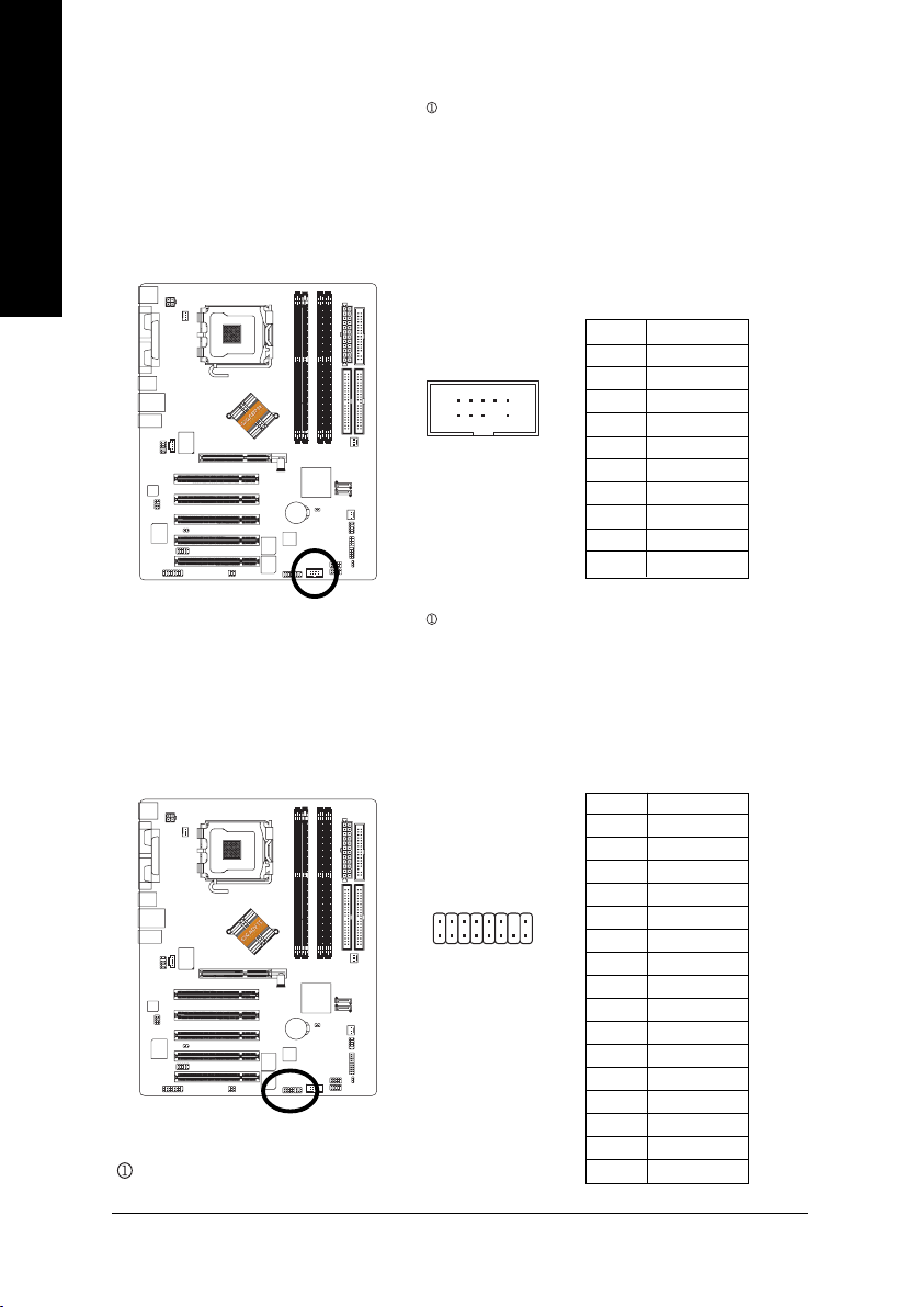
7) FDD (Floppy Connector)
English
Please connect the floppy drive ribbon cables to FDD. It supports 360K, 1.2M, 720K, 1.44M and
2.88M bytes floppy disk types.
The red stripe of the ribbon cable must be the same side with the Pin1.
34
2
33
1
8) PWR_LED
PWR_LED is connect with the system power indicator to indicate whether the system is on/off.
It will blink when the system enters suspend mode. If you use dual color LED, power LED will turn
to another color.
Pin No. Definition
1 MPD+
1
2 MPD-
3 MPD-
- 22 -GA-8IPE775 Series Motherboard
Page 27

9) F_PANEL (2 x 10 pins Connector)
Please connect the power LED, PC speaker, reset switch and power switch etc. of your chassis
front panel to the F_PANEL connector according to the pin assignment below.
Speaker
Connector
20
PW-
PW+
19
Reset Switch
NC
RES+
RESHD-
HD+
2
1
IDE Hard Disk
Active LED
SPEAK-
SPEAK+
Power Switch
MSG-
MSG+
Message LED/Power/
Sleep LED
HD (IDE Hard Disk Active LED) Pin 1: LED anode(+)
(Blue) Pin 2: LED cathode(-)
SPEAK (Speaker Connector) Pin 1: VCC(+)
(Amber) Pin 2- Pin 3: NC
Pin 4: Data(-)
RES (Reset Switch) Open: Normal Operation
(Green) Close: Reset Hardware System
PW (Power Switch) Open: Normal Operation
(Red) Close: Power On/Off
MSG(Message LED/ Power/ Sleep LED) Pin 1: LED anode(+)
(Yellow) Pin 2: LED cathode(-)
NC (Purple) N C
English
- 23 -
Hardware Installation Process
Page 28

10) F_AUDIO (Front Audio Connector)
English
11) SUR_CEN (Surround Center Connector)
If you want to use Front Audio connector, you must remove 5-6, 9-10 Jumper.
In order to utilize the front audio header, your chassis must have front audio connector. Also please
make sure the pin assigment on the cable is the same as the pin assigment on the MB header. To
find out if the chassis you are buying support front audio connector, please contact your dealer.
Please note, you can have the alternative of using front audio connector or of using rear audio
connector to play sound.
Pin No. Definition
1 MIC
12
109
2 GND
3 MIC_BIAS
4 Power
5 Front Audio (R)
6 Rear Audio (R)
7 Reserved
8 No Pin
9 Front Audio (L)
10 Rear Audio (L)
Please contact your nearest dealer for optional SUR_CEN cable.
1
78
- 24 -GA-8IPE775 Series Motherboard
2
Pin No. Definition
1 SUR OUTL
2 SUR OUTR
3 GND
4 No Pin
5 CENTER_OUT
6 BASS_OUT
7 AUX_L
8 AUX_R
Page 29

12) CD_IN (CD In Connector)
Connect CD-ROM or DVD-ROM audio out to the connector.
English
1
Pin No. Definition
1 CD-L
2 GND
3 GND
4 CD-R
13) SPDIF_IO (SPDIF In/Out Connector)
The SPDIF output is capable of providing digital audio to external speakers or compressed AC3
data to an external Dolby Digital Decoder. Use this feature only when your stereo system has
digital input function. Be careful with the polarity of the SPDIF_IO connector. Check the pin
assignment carefully while you connect the SPDIF cable, incorrect connection between the cable
and connector will make the device unable to work or even damage it. For optional SPDIF cable,
please contact your local dealer.
Pin No. Definition
62
5
1
1 VCC
2 No Pin
3 SPDIF
4 SPDIFI
5 GND
6 GND
- 25 -
Hardware Installation Process
Page 30

14) IR_CIR
English
15) F_USB1 / F_USB2 (Front USB Connector)
Make sure the pin 1 on the IR device is aling with pin one the connector. To enable the IR/CIR
function on the board, you are required to purchase an option IR/CIR module. To use IR function
only, please connect IR module to Pin1 to Pin5. Be careful with the polarity of the IR/CIR
connector. Check the pin assignment carefully while you connect the IR/CIR cable, incorrect
connection between the cable and connector will make the device unable to work or even damage
it. For optional IR/CIR cable, please contact your local dealer.
Pin No. Definition
1 VCC
10
6
5
1
2NC
3 IRRX
4 GND
5 IRTX
6NC
7 CIRRX
8 +5VSB
9 CIRTX
10 NC
Be careful with the polarity of the front USB connector. Check the pin assignment carefully while
you connect the front USB cable, incorrect connection between the cable and connector will make
the device unable to work or even damage it. For optional front USB cable, please contact your
local dealer.
2
19
- 26 -GA-8IPE775 Series Motherboard
Pin No. Definition
1 Power
2 Power
10
3 USB Dx-
4 USB Dy-
5 USB Dx+
6 USB Dy+
7 GND
8 GND
9 No Pin
10 NC
Page 31

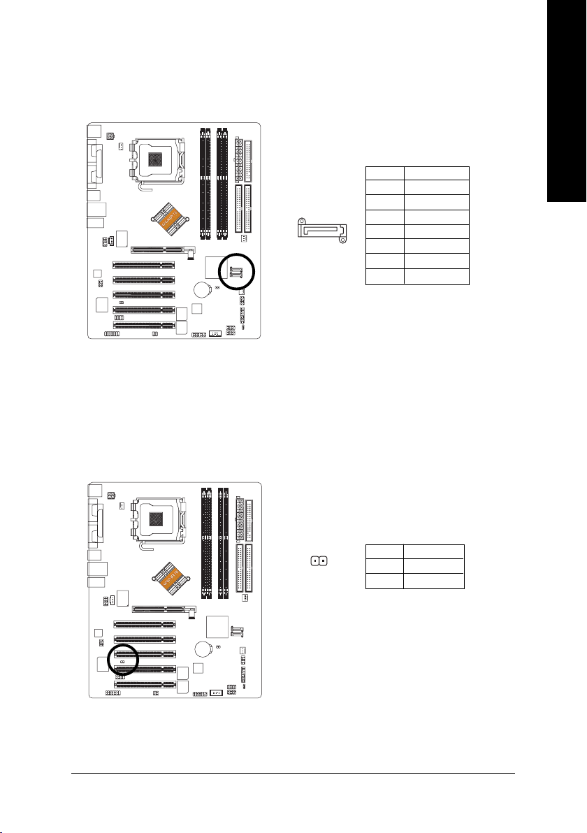
16) GAME (GAME Connector)
This connector supports joystick, MIDI keyboard and other relate audio devices.
Pin No. Definition
1 VCC
2 GRX1_R
3 GND
4 GPSA2
2
16
115
5 VCC
6 GPX2_R
7 GPY2_R
8 MSI_R
9 GPSA1
10 GND
11 GPY1_R
12 VCC
13 GPSB1
14 MSO_R
15 GPSB2
16 No Pin
17) INFO_LINK
This connector allows you to connect some external devices to provide you extra function. Check
the pin assignment while you connect the external device cable. Please contact your nearest
dealer for optional external device cable.
English
10
- 27 -
Pin No. Definition
1 SMBCLK
2 VCC
9
1
2
3 SMBDATA
4 GPIO
5 GND
6 GND
7 No Pin
8NC
9 +12V
10 +12V
Hardware Installation Process
Page 32
18) F1_1394 (IEEE 1394 Connector)
English
19) F2_1394 (IEEE 1394 Connector)
Please Note: Serial interface standard set by Institute of Electrical and Electronics Engineers, which
has features like high speed, high bandwidth and hot plug.
Be careful with the polarity of the IEEE1394 connector. Check the pin assignment carefully while you
connect the IEEE1394 cable, incorrect connection between the cable and connector will make the
device unable to work or even damage it. For optional IEEE1394 cable, please contact your local
dealer.
Pin No. Definition
210
19
1 TPA2+
2 TPA2-
3 GND
4 GND
5 TPB2+
6 TPB2-
7 No Pin
8 Power
9 Power
10 GND
Please Note: Serial interface standard set by Institute of Electrical and Electronics Engineers, which
has features like high speed, high bandwidth and hot plug.
Be careful with the polarity of the IEEE1394 connector. Check the pin assignment carefully while you
connect the IEEE1394 cable, incorrect connection between the cable and connector will make the
device unable to work or even damage it. For optional IEEE1394 cable, please contact your local
dealer.
Pin No. Definition
1 Power
2 Power
3 TPA0+
4 TPA0-
5 GND
6 GND
7 TPB0+
8 TPB0-
9 Power
10 Power
11 TPA1+
12 TPA1-
13 GND
14 No Pin
15 TPB1+
16 TPB1-
Only for GA-8IPE775 Pro.
2
1
16
15
- 28 -GA-8IPE775 Series Motherboard
Page 33
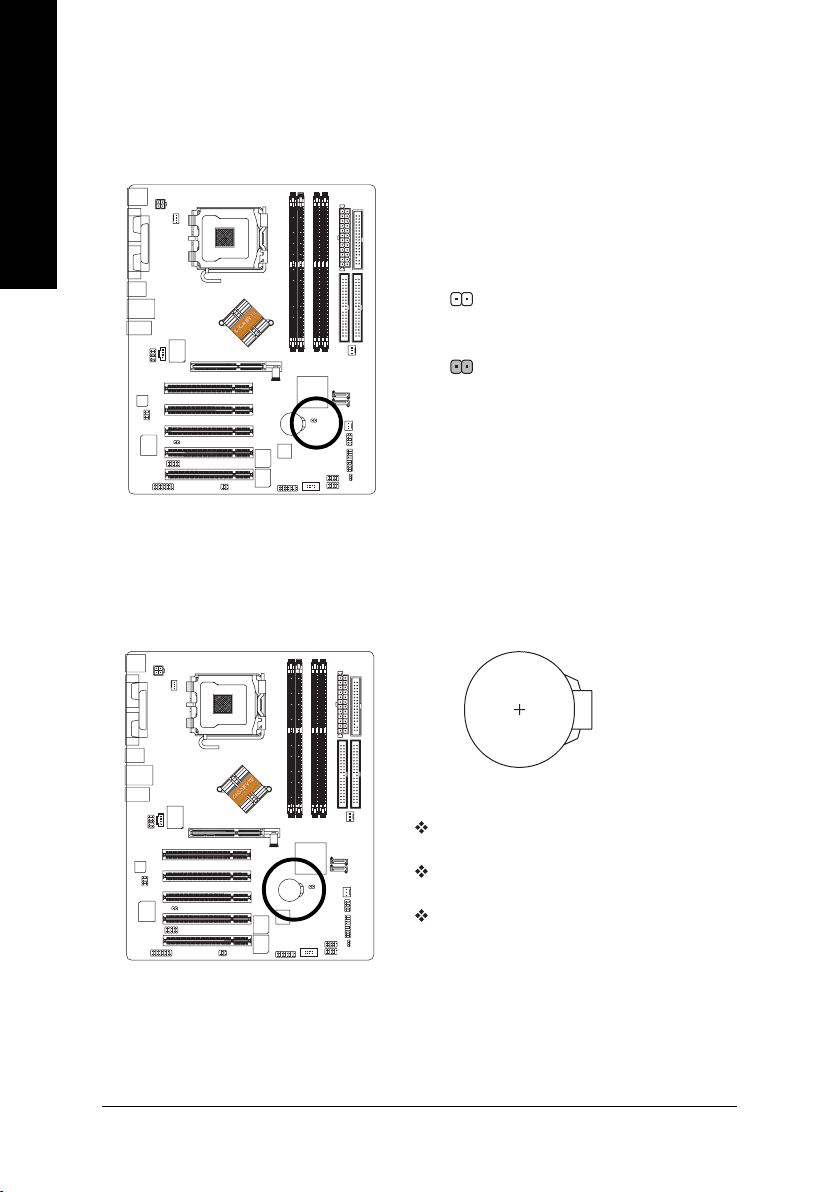
20) SATA0/SATA1 (Serial ATA Connector)
You can connect the Serial ATA device to this connector.
Pin No. Definition
1 GND
2 TXP
7
1
3 TXN
4 GND
5 RXN
6 RXP
7 GND
21) CI (Chassis Intrusion, Case Open)
This 2-pin connector allows your system to enable or disable the "Case Open" item in BIOS, if the
system case begin remove.
English
- 29 -
1
Pin No. Definition
1 Signal
2 GND
Hardware Installation Process
Page 34
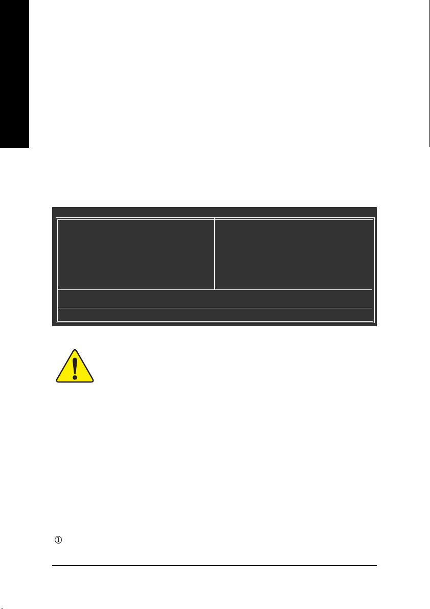
22) CLR_CMOS (Clear CMOS)
English
23) BAT (BATTERY)
You may clear the CMOS data to its default values by this jumper. To clear CMOS, temporarily
short 1-2 pin. Default doesn't include the "Shunter" to prevent from improper use this jumper.
Open: Normal
1
Short: Clear CMOS
1
CAUTION
Danger of explosion if battery is incorrectly
replaced.
Replace only with the same or equivalent type
recommended by the manufacturer.
Dispose of used batteries according to the
manufacturer's instructions.
If you want to erase CMOS...
1. Turn OFF the computer and unplug the power cord.
2. Remove the battery, wait for 30 second.
3. Re-install the battery.
4. Plug the power cord and turn ON the computer.
- 30 -GA-8IPE775 Series Motherboard
Page 35

Chapter 3 BIOS Setup
BIOS (Basic Input and Output System) includes a CMOS SETUP utility which allows user to configure
required settings or to activate certain system features.
The CMOS SETUP saves the configuration in the CMOS SRAM of the motherboard.
When the power is turned off, the battery on the motherboard supplies the necessary power to the CMOS
SRAM.
When the power is turned on, pushing the <Del> button during the BIOS POST (Power-On Self Test) will
take you to the CMOS SETUP screen. You can enter the BIOS setup screen by pressing "Ctrl + F1".
When setting up BIOS for the first time, it is recommended that you save the current BIOS to a disk in the
event that BIOS needs to be reset to its original settings. If you wish to upgrade to a new BIOS, either
Gigabyte's Q-Flash or @BIOS utility can be used.
Q-Flash allows the user to quickly and easily update or backup BIOS without entering the operating
system.
@BIOS is a Windows-based utility that does not require users to boot to DOS before upgrading BIOS but
directly download and update BIOS from the Internet.
CONTROL KEYS
<Ç> Move to previous item
<È> Move to next item
<Å> Move to the item in the left hand
<Æ> Move to the item in the right hand
Enter Select item
<Esc> Main Menu - Quit and not save changes into CMOS Status Page Setup Menu and
Option Page Setup Menu - Exit current page and return to Main Menu
<+/PgUp> Increase the numeric value or make changes
<-/PgDn> Decrease the numeric value or make changes
<F1> General help, only for Status Page Setup Menu and Option Page Setup Menu
<F2> Item Help
<F3> Reserved
<F4> Reserved
<F5> Restore the previous CMOS value from CMOS, only for Option Page Setup Menu
<F6> Load the file-safe default CMOS value from BIOS default table
<F7> Load the Optimized Defaults
<F8> Dual BIOS /Q-Flash function
<F9> System Information
<F10> Save all the CMOS changes, only for Main Menu
English
Only for GA-8IPE775 Pro.
- 31 - BIOS Setup
Page 36
GETTING HELP
The on-line description of the highlighted setup function is displayed at the bottom of the screen.
English
Press F1 to pop up a small help window that describes the appropriate keys to use and the possible
selections for the highlighted item. To exit the Help Window press <Esc>.
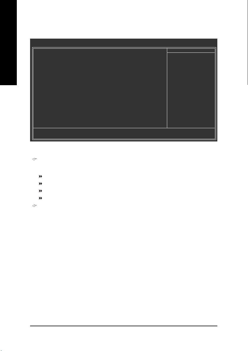
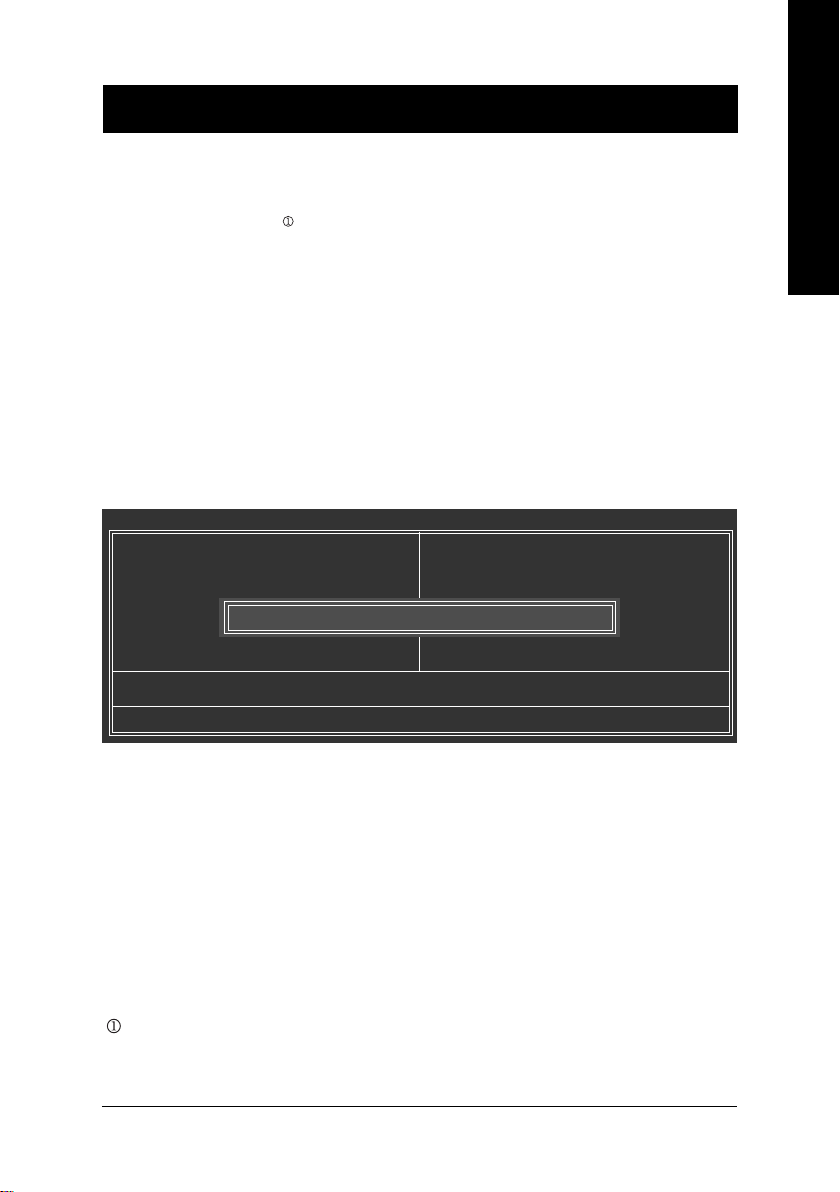
The Main Menu (For example: BIOS Ver. : 8IPE775 Pro.D4)
Once you enter Award BIOS CMOS Setup Utility, the Main Menu will appear on the screen. The Main
Menu allows you to select from eight setup functions and two exit choices. Use arrow keys to select
among the items and press <Enter> to accept or enter the sub-menu.
Main Menu
Status Page Setup Menu / Option Page Setup Menu
CMOS Setup Utility-Copyright (C) 1984-2004 Award Software
` Standard CMOS Features
` Advanced BIOS Features
` Integrated Peripherals
` Power Management Setup
` PnP/PCI Configurations
` PC Health Status
` Frequency/Voltage Control
ESC: Quit KLJI: Select Item
F8: Dual BIOS 1/Q-Flash F10: Save & Exit Setup
Time, Date, Hard Disk Type...
Load Fail-Safe Defaults
Load Optimized Defaults
Set Supervisor Password
Set User Password
Save & Exit Setup
Exit Without Saving
If you can't find the setting you want, please press "Ctrl+F1" to
search the advanced option widden.
zz
z Standard CMOS Features
zz
This setup page includes all the items in standard compatible BIOS.
zz
z Advanced BIOS Features
zz
This setup page includes all the items of Award special enhanced features.
zz
z Integrated Peripherals
zz
This setup page includes all onboard peripherals.
Only for GA-8IPE775 Pro.
- 32 -GA-8IPE775 Series Motherboard
Page 37

zz
z Power Management Setup
zz
This setup page includes all the items of Green function features.
zz
z PnP/PCI Configurations
zz
This setup page includes all the configurations of PCI & PnP ISA resources.
zz
z PC Health Status
zz
This setup page is the System auto detect Temperature, voltage, fan, speed.
zz
z Frequency/Voltage Control
zz
This setup page is control CPU's clock and frequency ratio.
zz
z Load Fail-Safe Defaults
zz
Fail-Safe Defaults indicates the value of the system parameters which the system would
be in safe configuration.
zz
z Load Optimized Defaults
zz
Optimized Defaults indicates the value of the system parameters which the system would
be in best performance configuration.
zz
z Set Supervisor password
zz
Change, set, or disable password. It allows you to limit access to the system and Setup,
or just to Setup.
zz
z Set User password
zz
Change, set, or disable password. It allows you to limit access to the system.
zz
z Save & Exit Setup
zz
Save CMOS value settings to CMOS and exit setup.
zz
z Exit Without Saving
zz
Abandon all CMOS value changes and exit setup.
English
- 33 - BIOS Setup
Page 38
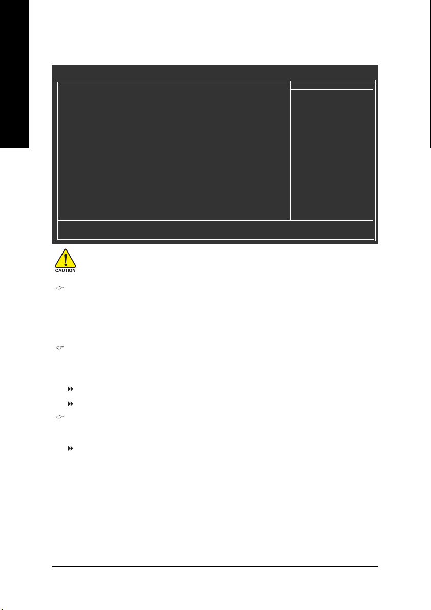
Standard CMOS Features
English
CMOS Setup Utility-Copyright (C) 1984-2004 Award Software
Date (mm:dd:yy) Mon, May 10 2004
Time (hh:mm:ss) 22:31:24
` IDE Channel 0 Master [None]
` IDE Channel 0 Slave [None]
` IDE Channel 1 Master [None]
` IDE Channel 1 Slave [None]
Drive A [1.44M, 3.5"]
Drive B [None]
Floppy 3 Mode Suport [Disabled]
Holt On [All, But Keyboard]
Base Memory 640K
Extended Memory 127M
Total Memory 128M
KLJI: Move Enter: Select +/-/PU/PD: Value F10: Save ESC: Exit F1: General Help
F5: Previous Values F6: Fail-Save Default F7: Optimized Defaults
Standard CMOS Features
Item Help
Menu Level`
Change the day, month,
year
<Week>
Sun. to Sat.
<Month>
Jan. to Dec.
<Day>
1 to 31 (or maximum
allowed in the month)
<Year>
1999 to 2098
Date
The date format is <week>, <month>, <day>, <year>.
Week The week, from Sun to Sat, determined by the BIOS and is display only
Month The month, Jan. Through Dec.
Day The day, from 1 to 31 (or the maximum allowed in the month)
Year The year, from 1999 through 2098
Time
The times format in <hour> <minute> <second>. The time is calculated base on the 24-hour
military-time clock. For example, 1 p.m. is 13:00:00.
- 34 -GA-8IPE775 Series Motherboard
Page 39

IDE Channel 0 Master, Slave / IDE Channel 1 Master, Slave
IDE HDD Auto-Detection Press "Enter" to select this option for automatic device detection.
IDE Channel 0 Master(Slave) / IDE Channel 1 Master(Slave) IDE Device Setup. You can use
one of three methods:
Auto Allows BIOS to automatically detect IDE devices during POST(default)
None Select this if no IDE devices are used and the system will skip the automatic
detection step and allow for faster system start up.
Manual User can manually input the correct settings
Access Mode Use this to set the access mode for the hard drive. The four options are:
CHS/LBA/Large/Auto(default:Auto)
Hard drive information should be labeled on the outside drive casing. Enter the appropriate option
based on this information.
Cylinder Number of cylinders
Head Number of heads
Precomp Write precomp
Landing Zone Landing zone
Sector Number of sectors
If a hard disk has not been installed, select NONE and press <Enter>.
Drive A / Drive B
The category identifies the types of floppy disk drive A or drive B that has been installed in the
computer.
None No floppy drive installed
360K, 5.25" 5.25 inch PC-type standard drive; 360K byte capacity.
1.2M, 5.25" 5.25 inch AT-type high-density drive; 1.2M byte capacity
(3.5 inch when 3 Mode is Enabled).
720K, 3.5" 3.5 inch double-sided drive; 720K byte capacity
1.44M, 3.5" 3.5 inch double-sided drive; 1.44M byte capacity.
2.88M, 3.5" 3.5 inch double-sided drive; 2.88M byte capacity.
English
- 35 - BIOS Setup
Page 40

English
Floppy 3 Mode Support (for Japan Area)
Disabled Normal Floppy Drive. (Default value)
Drive A Drive A is 3 mode Floppy Drive.
Drive B Drive B is 3 mode Floppy Drive.
Both Drive A & B are 3 mode Floppy Drives.
Halt on
The category determines whether the computer will stop if an error is detected during power up.
NO Errors The system boot will not stop for any error that may be detected and
you will be prompted.
All Errors Whenever the BIOS detects a non-fatal error the system boot will be
stopped.
All, But Keyboard The system boot will not stop for all errors except a keyboard error.
(Default value)
All, But Diskette The system boot will not stop for all errors except a disk error.
All, But Disk/Key The system boot will not stop for all errors except keyboard and disk
errors.
Memory
The category is display-only which is determined by POST (Power On Self Test) of the BIOS.
Base Memory
The POST of the BIOS will determine the amount of base (or conventional) memory installed
in the system.
The value of the base memory is typically 512 K for systems with 512K memory installed on
the motherboard, or 640 K for systems with 640 K or more memory installed on the motherboard.
Extended Memory
The BIOS determines how much extended memory is present during the POST.
This is the amount of memory located above 1MB in the CPU's memory address map.
- 36 -GA-8IPE775 Series Motherboard
Page 41

Advanced BIOS Features
CMOS Setup Utility-Copyright (C) 1984-2004 Award Software
X Hard Disk Boot Priority [Press Enter]
First Boot Device [Floppy]
Second Boot Device [Hard Disk]
Third Boot Device [CDROM]
Password Check [Setup]
Boot to OS2 or DR-DOS [No]
# CPU Hyper-Threading [Enabled]
Limit CPUID Max. to 3 [Enabled]
KLJI: Move Enter: Select +/-/PU/PD: Value F10: Save ESC: Exit F1: General Help
F5: Previous Values F6: Fail-Save Default F7: Optimized Defaults
" # " System will detect automatically and show up when you install the Intel® Pentium® 4 processor with
HT Technology.
Hard Disk Boot Priority
Select boot sequence for onboard(or add-on cards) SCSI, RAID, etc.
Use < > or < > to select a device, then press<+> to move it up, or <-> to move it down the list.
Press <ESC> to exit this menu.
First / Second / Third Boot Device
0 This feature allows you to select the boot device priority.
Floppy Select your boot device priority by Floppy.
LS120 Select your boot device priority by LS120.
Hard Disk Select your boot device priority by Hard Disk.
CDROM Select your boot device priority by CDROM.
ZIP Select your boot device priority by ZIP.
USB-FDD Select your boot device priority by USB-FDD.
USB-ZIP Select your boot device priority by USB-ZIP.
USB-CDROM Select your boot device priority by USB-CDROM.
USB-HDD Select your boot device priority by USB-HDD.
LAN Select your boot device priority by LAN.
Disabled Select your boot device priority by Disabled.
Advanced BIOS Features
Item Help
Menu Level`
Select Hard Disk Boot
Device Priority
English
- 37 - BIOS Setup
Page 42

English
Password Check
Setup The system will boot but will not access to Setup page if the correct
password is not entered at the prompt. (Default value)
System The system will not boot and will not access to Setup page if the correct
password is not entered at the prompt.
Boot to OS2 or DR-DOS
Yes If you are running OS/2 or DR-DOS with greater than 64MB of RAM on the
system.
No Disable this function. (Default value)
CPU Hyper-Threading
Enabled Enables CPU Hyper Threading Feature. Please note that this feature is
only working for operating system with multi processors mode supported.
(Default value)
Disabled Disables CPU Hyper Threading.
Limit CPUID Max. to 3
Enabled Limit CPUID Maximum value to 3 when use older OS like NT4. (Default value)
Disabled Disables CPUID Limit for windows XP.
- 38 -GA-8IPE775 Series Motherboard
Page 43

Integrated Peripherals
CMOS Setup Utility-Copyright (C) 1984-2004 Award Software
On-Chip Primary PCI IDE [Enabled]
On-Chip Secondary PCI IDE [Enabled]
On-Chip SATA [Auto]
x SATA Port0 Configure as SATA Port0
SATA Port1 Configure as SATA Port1
USB Controller [Enabled]
USB 2.0 Controller [Enabled]
USB Keyboard Support [Disabled]
USB Mouse Support [Disabled]
AC97 Audio [Auto]
Onboard H/W 1394 1 [Enabled]
Onboard H/W LAN 12 [Enabled]
Onboard LAN Boot ROM 12 [Disabled]
Onboard Serial Port 1 [3F8/IRQ4]
Onboard Serial Port 2 [2F8/IRQ3]
UART Mode Select [Normal]
x UR2 Duplex Mode Half
Onboard Parallel Port [378/IRQ7]
Parallel Port Mode [SPP]
KLJI: Move Enter: Select +/-/PU/PD: Value F10: Save ESC: Exit F1: General Help
F5: Previous Values F6: Fail-Save Default F7: Optimized Defaults
Integrated Peripherals
Item Help
Menu Level`
If a hard disk
controller card is
used, set at Disabled
[Enabled]
Enable on-chip IDE
Port
[Disabled]
Disable on-chip IDE
Port
English
CMOS Setup Utility-Copyright (C) 1984-2004 Award Software
x ECP Mode Use DMA 3
Game Port Address [201]
Midi Port Address [Disabled]
Midi Port IRQ 10
CIR Port Address [Disabled]
x CIR Port IRQ 11
KLJI: Move Enter: Select +/-/PU/PD: Value F10: Save ESC: Exit F1: General Help
F5: Previous Values F6: Fail-Save Default F7: Optimized Defaults
Integrated Peripherals
Item Help
Menu Level`
Only for GA-8IPE775 Pro. Only for GA-8IPE775-G.
- 39 - BIOS Setup
Page 44

English
On-Chip Primary PCI IDE
Enabled Enable onboard 1st channel IDE port. (Default value)
Disabled Disable onboard 1st channel IDE port.
On-Chip Secondary PCI IDE
Enabled Enable onboard 2nd channel IDE port. (Default value)
Disabled Disable onboard 2nd channel IDE port.
On-chip SATA
Disabled Disable SATA controller.
Auto When there is no device to be plugged in IDE1 or IDE2, SATA controller
will remap to IDE controller. (Default value)
Manual Set SATA Mode manually.
SATA Port0 Configure as
IDE Pri. Master Remap SATA Port 0 to IDE Pri. Master.
IDE Pri. Slave Remap SATA Port 0 to IDE Pri. Slave.
IDE Sec. Master Remap SATA Port 0 to IDE Sec. Master.
IDE Sec. Slave Remap SATA Port 0 to IDE Sec. Slave.
SATA Port0 SATA controller set to SATA port0. As this mode, it support by WinXP or
later OS only. (Default value)
SATA Port1 SATA controller set to SATA port1. As this mode, it support by WinXP or
later OS only.
SATA Port1 Configure as
The values depend on SATA Port0.
USB Controller
Enabled Enable USB Controller. (Default value)
Disabled Disable USB Controller.
USB 2.0 Controller
Disable this function if you are not using onboard USB 2.0 feature.
Enabled Enable USB 2.0 Controller. (Default value)
Disabled Disable USB 2.0 Controller.
USB Keyboard Support
Enabled Enable USB Keyboard Support.
Disabled Disable USB Keyboard Support. (Default value)
- 40 -GA-8IPE775 Series Motherboard
Page 45

USB Mouse Support
Enabled Enable USB Mouse Support.
Disabled Disable USB Mouse Support. (Default value)
AC97 Audio
Auto Auto detect AC'97 audio function. (Default value)
Disabled Disable AC'97 audio function.
Onboard H/W 1394
Enabled Enable onboard IEEE 1394 function.(Default value)
Disabled Disable this function.
Onboard H/W LAN
Enabled Enable Onboard H/W LAN function. (Default value)
Disabled Disable this function.
Onboard LAN Boot ROM
This function decide whether to invoke the boot ROM of the onboard LAN chip.
Disabled Disable this function. (Default Value)
Enabled Enable this function.
Onboard Serial Port 1
Auto BIOS will automatically setup the port 1 address.
3F8/IRQ4 Enable onboard Serial port 1 and address is 3F8. (Default value)
2F8/IRQ3 Enable onboard Serial port 1 and address is 2F8.
3E8/IRQ4 Enable onboard Serial port 1 and address is 3E8.
2E8/IRQ3 Enable onboard Serial port 1 and address is 2E8.
Disabled Disable onboard Serial port 1.
Onboard Serial Port 2
Auto BIOS will automatically setup the port 2 address.
3F8/IRQ4 Enable onboard Serial port 2 and address is 3F8.
2F8/IRQ3 Enable onboard Serial port 2 and address is 2F8. (Default value)
3E8/IRQ4 Enable onboard Serial port 2 and address is 3E8.
2E8/IRQ3 Enable onboard Serial port 2 and address is 2E8.
Disabled Disable onboard Serial port 2.
English
Only for GA-8IPE775 Pro.
Only for GA-8IPE775-G.
- 41 - BIOS Setup
Page 46

English
UART Mode Select
This item allows you to determine which Infra Red(IR) function of Onboard I/O chip.
ASKIR Set onboard I/O chip UART to ASKIR Mode.
IrDA Set onboard I/O chip UART to IrDA Mode.
Normal Set onboard I/O chip UART to Normal Mode. (Default Value)
UR2 Duplex Mode
This feature allows you to seclect IR mode.
This function will available when "UART Mode Select" doesn't set at Normal.
Half IR Function Duplex Half. (Default value)
Full IR Function Duplex Full.
Onboard Parallel port
This feature allows you to select from a given set of parameters if the parallel port uses the onboard
I/O controller.
Disabled Disable onboard LPT port.
378/IRQ7 Enable onboard LPT port and address is 378/IRQ7. (Default value)
278/IRQ5 Enable onboard LPT port and address is 278/IRQ5.
3BC/IRQ7 Enable onboard LPT port and address is 3BC/IRQ7.
Parallel Port Mode
This feature allows you to connect with an advanced printer via the port mode it supports.
SPP Using Parallel port as Standard Parallel Port. (Default value)
EPP Using Parallel port as Enhanced Parallel Port.
ECP Using Parallel port as Extended Capabilities Port.
ECP+EPP Using Parallel port as ECP & EPP mode.
ECP Mode Use DMA
This feature allows you to select Direct Memory Access(DMA) channel if the ECP mode selected.
This function will available when "Parallel Port Mode" set at ECP or ECP+EPP.
3 Set ECP Mode Use DMA to 3. (Default value)
1 Set ECP Mode Use DMA to 1.
Game Port Address
201 Set Game Port Address to 201. (Default value)
209 Set Game Port Address to 209.
Disabled Disable this function.
Midi Port Address
300 Set Midi Port Address to 300.
330 Set Midi Port Address to 330.
Disabled Disable this function. (Default value)
- 42 -GA-8IPE775 Series Motherboard
Page 47

Midi Port IRQ
5 Set Midi Port IRQ to 5.
10 Set Midi Port IRQ to 10. (Default value)
CIR Port Address
310 Set CIR Port Address to 310.
320 Set CIR Port Address to 320.
Disabled Disable this function. (Default value)
CIR Port IRQ
5 Set CIR Port IRQ to 5.
11 Set CIR Port IRQ to 11. (Default value)
Power Management Setup
CMOS Setup Utility-Copyright (C) 1984-2004 Award Software
ACPI Suspend Type [S1(POS)]
Power LED in S1 state [Blinking]
Off by Power button [Instant-off]
PME Event Wake Up [Enabled]
ModemRingOn/WakeOnLan [Enabled]
Resume by Alarm [Disabled]
x Date (of Month) Alarm Everyday
x Time (hh:mm:ss) Alarm 0 : 0 : 0
Power On By Mouse [Disabled]
Power On By Keyboard [Disabled]
x KB Power ON Password Enter
AC Back Function [Soft-Off]
Power Management Setup
Item Help
Menu Level`
[S1]
Set suspend type to
Power On Suspend under
ACPI OS
[S3]
Set suspend type to
Suspend to RAM under
ACPI OS
English
KLJI: Move Enter: Select +/-/PU/PD: Value F10: Save ESC: Exit F1: General Help
F5: Previous Values F6: Fail-Save Default F7: Optimized Defaults
ACPI Suspend Type
S1(POS) Set ACPI suspend type to S1/POS(Power On Suspend). (Default value)
S3(STR) Set ACPI suspend type to S3/STR(Suspend To RAM).
Power LED in S1 state
Blinking In standby mode(S1), power LED will blink. (Default value)
Dual/OFF In standby mode(S1):
a. If use single color LED, power LED will turn off.
b. If use dual color LED, power LED will turn to another color.
- 43 - BIOS Setup
Page 48

English
Off by Power button
Instant-off Press power button then Power off instantly. (Default value)
Delay 4 Sec. Press power button 4 sec. to Power off. Enter suspend if button is pressed
less than 4 sec.
PME Event Wake Up
Disabled Disable this function.
Enabled Enable PME Event Wake up. (Default value)
ModemRingOn/WakeOnLAN
An incoming call via modem can awake the system from any suspend state or an input signal
comes from the other client server on the LAN can awake the system from any suspend state.
Disabled Disable Modem Ring on/wake on Lan function.
Enabled Enable Modem Ring on/wake on Lan. (Default value)
Resume by Alarm
You can set "Resume by Alarm" item to enabled and key in Data/time to power on system.
Disabled Disable this function. (Default value)
Enabled Enable alarm function to POWER ON system.
If RTC Alarm Lead To Power On is Enabled.
Date (of Month) Alarm : Everyday, 1~31
Time (hh: mm: ss) Alarm : (0~23) : (0~59) : (0~59)
Power On By Mouse
Disabled Disable this function. (Default value)
Mouse Click Double click on PS/2 mouse left button to power on the system.
Power On By Keyboard
This feature allows you to set the method for powering-on the system.
The option "Password" allows you to set up to 5 alphanumeric characters to power-on the system.
The option "Keyboard 98" allows you to use the standard keyboard 98 to power on the system.
Password Enter from 1 to 5 characters to set the Keyboard Power On Password.
Disabled Disabled this function. (Default value)
Keyboard 98 If your keyboard have "POWER Key" button, you can press the key to
power on the system.
KB Power ON Password
When "Power On by Keyboard" set at Password, you can set the password here.
Enter Input password (from 1 to 5 characters) and press Enter to set the Keyboard
Power On password.
- 44 -GA-8IPE775 Series Motherboard
Page 49

AC BACK Function
Soft-Off When AC-power back to the system, the system will be in "Off" state.
(Default value)
Full-On When AC-power back to the system, the system always in "On" state.
Memory When AC-power back to the system, the system will return to the Last state
before AC-power off.
PnP/PCI Configurations
CMOS Setup Utility-Copyright (C) 1984-2004 Award Software
PCI 1/PCI 5 IRQ Assignment [Auto]
PCI 2 IRQ Assignment [Auto]
PCI 3 IRQ Assignment [Auto]
PCI 4 IRQ Assignment [Auto]
KLJI: Move Enter: Select +/-/PU/PD: Value F10: Save ESC: Exit F1: General Help
F5: Previous Values F6: Fail-Save Default F7: Optimized Defaults
PnP/PCI Configurations
Item Help
Menu Level`
English
PCI 1/PCI 5 IRQ Assignment
Auto Auto assign IRQ to PCI 1/PCI 5. (Default value)
3,4,5,7,9,10,11,12,14,15 Set IRQ 3,4,5,7,9,10,11,12,14,15 to PCI 1/PCI 5.
PCI 2 IRQ Assignment
Auto Auto assign IRQ to PCI 2. (Default value)
3,4,5,7,9,10,11,12,14,15 Set IRQ 3,4,5,7,9,10,11,12,14,15 to PCI 2.
PCI 3 IRQ Assignment
Auto Auto assign IRQ to PCI 3. (Default value)
3,4,5,7,9,10,11,12,14,15 Set IRQ 3,4,5,7,9,10,11,12,14,15 to PCI 3.
PCI 4 IRQ Assignment
Auto Auto assign IRQ to PCI 4. (Default value)
3,4,5,7,9,10,11,12,14,15 Set IRQ 3,4,5,7,9,10,11,12,14,15 to PCI 4.
- 45 - BIOS Setup
Page 50

PC Health Status
English
CMOS Setup Utility-Copyright (C) 1984-2004 Award Software
Reset Case Open Status [Disabled]
Case Opened Yes
Vcore OK
DDR25V OK
+3.3V OK
+12V OK
Current CPU Temperature 50oC
Current CPU FAN Speed 4687 RPM
Current POWER FAN Speed 1 0 RPM
Current SYSTEM FAN Speed 0 RPM
CPU Warning Temperature [Disabled]
CPU FAN Fail Warning [Disabled]
POWER FAN Fail Warning 1 [Disabled]
SYSTEM FAN Fail Warning [Disabled]
CPU Smart FAN Control 12 [Enabled]
KLJI: Move Enter: Select +/-/PU/PD: Value F10: Save ESC: Exit F1: General Help
F5: Previous Values F6: Fail-Save Default F7: Optimized Defaults
PC Health Status
Item Help
Menu Level`
[Disabled]
Don't monitor
current fan speed
[Enabled]
Clear case open status
and set to be Disabled
at next boot
Reset Case Open Status
Disabled Don't reset case open status. (Default value)
Enabled Clear case open status at next boot.
Case Opened
If the case is closed, "Case Opened" will show "No".
If the case have been opened, "Case Opened" will show "Yes".
If you want to reset "Case Opened" value, set "Reset Case Open Status" to "Enabled" and save
CMOS, your computer will restart.
Current Voltage (V) Vcore / DDR25V / +3.3V / +12V
Detect system's voltage status automatically.
Current CPU Temperature
Detect CPU Temp. automatically.
Current CPU/POWER /SYSTEM FAN Speed (RPM)
Detect CPU/POWER/SYSTEM Fan speed status automatically.
Only for GA-8IPE775 Pro.
Only for GA-8IPE775-G.
- 46 -GA-8IPE775 Series Motherboard
Page 51

CPU Warning Temperature
60oC / 140oF Monitor CPU Temp. at 60oC / 140oF.
70oC / 158oF Monitor CPU Temp. at 70oC / 158oF.
80oC / 176oF Monitor CPU Temp. at 80oC / 176oF.
90oC / 194oF Monitor CPU Temp. at 90oC / 194oF.
Disabled Disable this function. (Default value)
CPU FAN Fail Warning
Disabled Fan Warning Function Disable. (Default value)
Enabled Fan Warning Function Enable.
POWER FAN Fail Warning
Disabled Fan Warning Function Disable. (Default value)
Enabled Fan Warning Function Enable.
SYSTEM FAN Fail Warning
Disabled Fan Warning Function Disable. (Default value)
Enabled Fan Warning Function Enable.
CPU Smart FAN Control
Disabled Disable this function.
Enabled Enable CPU Smart Fan control function.(Default value)
a. When the CPU temperature is higher than 70 degrees Celsius, CPU fan
will run at full speed.
b. When the CPU temperature is between 50 and 70 degrees Celsius,
CPU fan will run at high speed.
c. When the CPU temperature is between 40 and 50 degrees Celsius,
CPU fan will run at medium speed.
d. When the CPU temperature is lower than 40 degrees Celsius, CPU fan
will run at low speed.
English
Only for GA-8IPE775 Pro.
Only for GA-8IPE775-G.
- 47 - BIOS Setup
Page 52
Frequency/Voltage Control
English
CMOS Setup Utility-Copyright (C) 1984-2004 Award Software
CPU Clock Ratio [15X]
CPU Host Clock Control [Disabled]
x CPU Host Frequency (Mhz) 100
x AGP/PCI/SRC Fixed 66/33/100
Memory Frequency For [Auto]
Memory Frequency (Mhz) 266
AGP/PCI/SRC Frequency (Mhz) 66/33/100
DIMM OverVoltage Control [Normal]
AGP OverVoltage Control [Normal]
CPU Voltage Control [Normal]
Normal CPU Vcore 1.3875V
KLJI: Move Enter: Select +/-/PU/PD: Value F10: Save ESC: Exit F1: General Help
F5: Previous Values F6: Fail-Save Default F7: Optimized Defaults
Frequency/Voltage Control
Item Help
Menu Level`
Incorrect using these features may cause your system broken. For power End-User use only!
CPU Clock Ratio
This option will not be shown or not be available if you are using a CPU with the locked ratio.
This setup option will automatically assign by CPU detection.
The option will display "Locked" and read only if the CPU ratio is not changeable.
CPU Host Clock Control
Please note that if your system is overclocked and cannot restart, please wait 20secs.
for automatic system restart or clear the CMOS setup data and perform a safe restart.
Disabled Disable CPU Host Clock Control. (Default value)
Enabled Enable CPU Host Clock Control.
CPU Host Frequency (Mhz)
This item will be available when "CPU Host Clock Control" is set to Enabled.
100MHz ~ 355MHz Set CPU Host Clock from 100MHz to 355MHz.
If you use FSB400 Pentium 4 processor, please set "CPU Clock" to 100MHz.If you use FSB533
Pentium 4 processor, please set "CPU Clock" to 133MHz. If you use FSB800 Pentium 4
processor, please set "CPU Clock" to 200MHz.
Incorrect using it may cause your system broken. For power End-User use only!
- 48 -GA-8IPE775 Series Motherboard
Page 53

AGP/PCI/SRC Fixed
This item will be available when "CPU Host Clock Control" is set to Enabled.
Serial ATA device is very sensitive to SRC clock. SRC over clock may make Serial ATA device
function can't work properly.
Adjust AGP/PCI/SRC clock asychrohous with CPU.
Memory Frequency For
for FSB(Front Side Bus) frequency=400MHz,
2.66 Memory Frequency = Host clock X 2.66.
Auto Set Memory frequency by DRAM SPD data. (Default value)
for FSB(Front Side Bus) frequency=533MHz,
2.0 Memory Frequency = Host clock X 2.0.
2.5 Memory Frequency = Host clock X 2.5.
Auto Set Memory frequency by DRAM SPD data. (Default value)
for FSB(Front Side Bus) frequency=800MHz,
2.0 Memory Frequency = Host clock X 2.0.
1.6 Memory Frequency = Host clock X 1.6.
1.33 Memory Frequency = Host clock X 1.33.
Auto Set Memory frequency by DRAM SPD data. (Default value)
Memory Frequency (Mhz)
The values depend on CPU Host Frequency(Mhz).
AGP/PCI/SRC Frequency (Mhz)
The values depend on Fixed AGP/PCI/SRC Fixed.
DIMM OverVoltage Control
Normal Set DIMM OverVoltage Control to Normal. (Default value)
+0.1V Set DIMM OverVoltage Control to +0.1V.
+0.2V Set DIMM OverVoltage Control to +0.2V.
+0.3V Set DIMM OverVoltage Control to +0.3V.
Increase DRAM voltage may get stable for Over_Clock. But it may damage to DRAM module
when enable this feature.
AGP OverVoltage Control
Normal Set AGP OverVoltage Control to Normal. (Default value)
+0.1V Set AGP OverVoltage Control to +0.1V.
+0.2V Set AGP OverVoltage Control to +0.2V.
+0.3V Set AGP OverVoltage Control to +0.3V.
Increase AGP voltage may get stable for Over_Clock. But it may damage to AGP Card when
enable this feature.
English
- 49 - BIOS Setup
Page 54
English
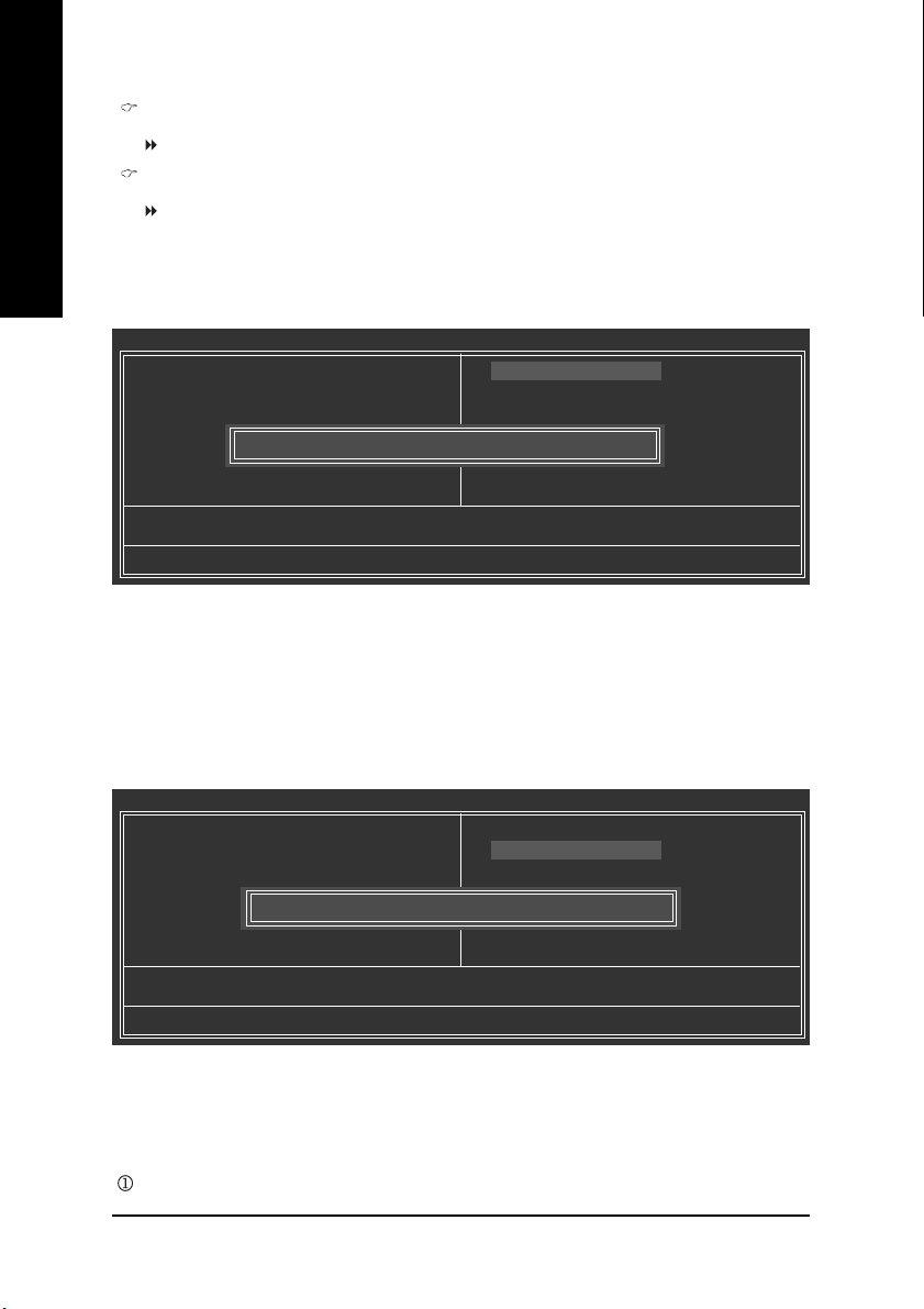
Load Fail-Safe Defaults
Fail-Safe defaults contain the most appropriate values of the system parameters that allow
minimum system performance.
CPU OverVoltage Control
Supports adjustable CPU Vcore from 0.8375V to 1.7600V. (Default value: Normal)
Normal CPU Vcore
Display your CPU Vcore Voltage.
CMOS Setup Utility-Copyright (C) 1984-2004 Award Software
` Standard CMOS Features
` Advanced BIOS Features
` Integrated Peripherals
` Power Management Setup
` PnP/PCI Configurations
` PC Health Status
` Frequency/Voltage Control
ESC: Quit KLJI: Select Item
F8: Dual BIOS 1/Q-Flash F10: Save & Exit Setup
Load Fail-Safe Defaults (Y/N)? N
Load Fail-Safe Defaults
Load Fail-Safe Defaults
Load Optimized Defaults
Set Supervisor Password
Set User Password
Save & Exit Setup
Exit Without Saving
Load Optimized Defaults
CMOS Setup Utility-Copyright (C) 1984-2004 Award Software
` Standard CMOS Features
` Advanced BIOS Features
` Integrated Peripherals
` Power Management Setup
` PnP/PCI Configurations
` PC Health Status
` Frequency/Voltage Control
ESC: Quit KLJI: Select Item
F8: Dual BIOS 1/Q-Flash F10: Save & Exit Setup
Load Optimized Defaults (Y/N)? N
Load Optimized Defaults
Selecting this field loads the factory defaults for BIOS and Chipset Features which the
system automatically detects.
Only for GA-8IPE775 Pro.
Load Fail-Safe Defaults
Load Optimized Defaults
Set Supervisor Password
Set User Password
Save & Exit Setup
Exit Without Saving
- 50 -GA-8IPE775 Series Motherboard
Page 55

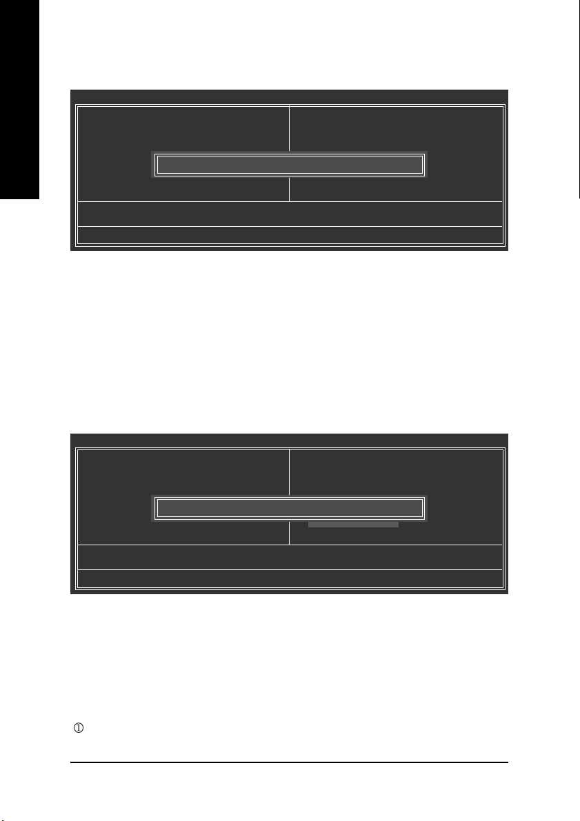
Set Supervisor/User Password
CMOS Setup Utility-Copyright (C) 1984-2004 Award Software
` Standard CMOS Features
` Advanced BIOS Features
` Integrated Peripherals
` Power Management Setup
` PnP/PCI Configurations
` PC Health Status
` Frequency/Voltage Control
ESC: Quit KLJI: Select Item
F8: Dual BIOS 1/Q-Flash F10: Save & Exit Setup
Enter Password:
Change/Set/Disable Password
When you select this function, the following message will appear at the center of the screen to assist
you in creating a password.
Type the password, up to eight characters, and press <Enter>. You will be asked to confirm the
password. Type the password again and press <Enter>. You may also press <Esc> to abort the
selection and not enter a password.
To disable password, just press <Enter> when you are prompted to enter password. A message
"PASSWORD DISABLED" will appear to confirm the password being disabled. Once the password is
disabled, the system will boot and you can enter Setup freely.
The BIOS Setup program allows you to specify two separate passwords:
SUPERVISOR PASSWORD and a USER PASSWORD. When disabled, anyone may access all BIOS
Setup program function. When enabled, the Supervisor password is required for entering the BIOS
Setup program and having full configuration fields, the User password is required to access only
basic items.
If you select "System" at "Password Check" in Advance BIOS Features Menu, you will be prompted
for the password every time the system is rebooted or any time you try to enter Setup Menu.
If you select "Setup" at "Password Check" in Advance BIOS Features Menu, you will be prompted
only when you try to enter Setup.
Load Fail-Safe Defaults
Load Optimized Defaults
Set Supervisor Password
Set User Password
Save & Exit Setup
Exit Without Saving
English
Only for GA-8IPE775 Pro.
- 51 - BIOS Setup
Page 56
Save & Exit Setup
English
Type "Y" will quit the Setup Utility and save the user setup value to RTC CMOS.
Type "N" will return to Setup Utility.
Exit Without Saving
CMOS Setup Utility-Copyright (C) 1984-2004 Award Software
` Standard CMOS Features
` Advanced BIOS Features
` Integrated Peripherals
` Power Management Setup
` PnP/PCI Configurations
` PC Health Status
` Frequency/Voltage Control
ESC: Quit KLJI: Select Item
F8: Dual BIOS 1/Q-Flash F10: Save & Exit Setup
Save to CMOS and EXIT (Y/N)? Y
Save & Exit Setup
Quit Without Saving (Y/N)? N
Abandon all Data
Load Fail-Safe Defaults
Load Optimized Defaults
Set Supervisor Password
Set User Password
Save & Exit Setup
Exit Without Saving
Load Fail-Safe Defaults
Load Optimized Defaults
Set Supervisor Password
Set User Password
Save & Exit Setup
Exit Without Saving
Type "Y" will quit the Setup Utility without saving to RTC CMOS.
Type "N" will return to Setup Utility.
Only for GA-8IPE775 Pro.
- 52 -GA-8IPE775 Series Motherboard
Page 57
Revision History
Chapter 4 Technical Reference
Flash BIOS Method Introduction
Method 1: Dual BIOS /Q-Flash
A. What is Dual BIOS Technology?
Dual BIOS means that there are two system BIOS (ROM) on the motherboard, one is the Main
BIOS and the other is Backup BIOS. Under the normal circumstances, the system works on the
Main BIOS. If the Main BIOS is corrupted or damaged, the Backup BIOS can take over while the
system is powered on. This means that your PC will still be able to run stably as if nothing has
happened in your BIOS.
B. How to use Dual BIOS and Q-Flash Utility?
a. After power on the computer, pressing <Del> immediately during POST (Power On Self Test) it will
allow you to enter Award BIOS CMOS SETUP, then press <F8> to enter Flash utility.
CMOS Setup Utility-Copyright (C) 1984-2004 Award Software
` Standard CMOS Features
` Advanced BIOS Features
` Integrated Peripherals
` Power Management Setup
` PnP/PCI Configurations
` PC Health Status
` Frequency/Voltage Control
ESC: Quit KLJI: Select Item
F8: Dual BIOS1/Q-Flash F10: Save & Exit Setup
Enter Dual BIOS/Q-Flash Utility (Y/N)? Y
Load Fail-Safe Defaults
Load Optimized Defaults
Set Supervisor Password
Set User Password
Save & Exit Setup
Exit Without Saving
English
Only for GA-8IPE775 Pro.
- 53 -
Technical Reference
Page 58

b. Award Dual BIOS Flash ROM Programming Utility
English
c. Dual BIOS Item explanation:
Wide Range Protection: Disable(Default), Enable
Status 1:
If any failure (ex. Update ESCD failure, checksum error or reset…) occurs in the Main BIOS, just
before the Operating System is loaded and after the power is on, and that the Wide Range Protection
is set to "Enable", the PC will boot from Backup BIOS automatically.
Status 2:
If the ROM BIOS on peripherals cards(ex. SCSI Cards, LAN Cards,..) emits signals torequest
restart of the system after the user make any alteration on it, the boot up BIOS will not be changed to
the Backup BIOS.
Boot From : Main BIOS(Default), Backup BIOS
Status 1:
Status 2:
will become gray and will not be changed by user.
Dual BIOS Utility V1.30
Boot From....................................................... Main Bios
Main ROM Type/Size...................................... SST 49LF003A 512K
Backup ROM Type/Size.................................. SST 49LF003A 512K
Wide Range Protection Disable
Boot From Main Bios
Auto Recovery Enable
Halt On Error Disable
Keep DMI Data Enable
Copy Main ROM Data to Backup
Load Default Settings
Save Settings to CMOS
Q-Flash Utility
Update Main BIOS from Floppy
Update Backup BIOS from Floppy
Save Main BIOS to Floppy
Save Backup BIOS to Floppy
PgDn/PgUp: Modify KL: Move ESC: Reset F10: Power Off
The user can set to boot from main BIOS or Backup BIOS.
If one of the main BIOS or the Backup BIOS fails, this item "Boot From : Main BIOS(Default)"
- 54 -GA-8IPE775 Series Motherboard
Page 59

Auto Recovery : Enable(Default), Disable
When one of the Main BIOS or Backup BIOS occurs checksum failure, the working BIOS will
automatically recover the BIOS of checksum failure.
(In the Power Management Setup of the BIOS Setting, if ACPI Suspend Type is set to Suspend to
RAM, the Auto Recovery will be set to Enable automatically.)
(If you want to enter the BIOS setting, please press "Del" key when the boot screen appears.)
Halt On Error : Disable(Default), Enable
If the BIOS occurs a checksum error or the Main BIOS occurs a WIDE RANGE PROTECTION
error and Halt On Error set to Enable, the PC will show messages on the boot screen, and the
system will pause and wait for the user's instruction.
If Auto Recovery :Disable, it will show <or the other key to continue.>
If Auto Recovery :Enable, it will show <or the other key to Auto Recover.>
Keep DMI Data : Enable(Default), Disable
Enable: The DMI data won't be replaced by flashing new BIOS.(recommend)
Disable: The DMI data will be replaced by flashing new BIOS.
Copy Main ROM Data to Backup
(If you boot from Backup ROM, this item will change to Copy Backup ROM Data to Main)
Auto recovery message:
BIOS Recovery: Main to Backup
The means that the Main BIOS works normally and could automatically recover the Backup BIOS.
BIOS Recovery: Backup to Main
The means that the Backup BIOS works normally and could automatically recover the Main BIOS.
(This auto recovery utility is set by system automatically and can’t be changed by user.)
Load Default Settings
Load dual BIOS default value.
Save Settings to CMOS
Save revised setting.
English
- 55 -
Technical Reference
Page 60

English
Q-Flash
it is in the BIOS menu.
Q-FlashTM is a BIOS flash utility embedded in Flash ROM.
With this utility, users only have to stay in the BIOS menu
when they want to update BIOS. Q-Flash
™
allows users to
flash BIOS without any utility in DOS or Windows. Using
TM
indicating no more fooling around with any complicated instructions and operating system since
Please note that because updating BIOS has potential risk, please do it with caution!! We
are sorry that Gigabyte Technology Co., Ltd is not responsible for damages of system
because of incorrect manipulation of updating BIOS to avoid any claims from end-users.
Before You Begin:
TM
Before you start updating BIOS with the Q-Flash
1. Download the latest BIOS for your motherboard from Gigabyte's website.
2. Extract the BIOS file downloaded and save the BIOS file (the one with model name.Fxx. For
example, 8KNXPU.Fba) to a floppy disk.
3. Reboot your PC and press Del to enter BIOS menu.
The BIOS upgrading guides below are separated into two parts.
If your motherboard has dual-BIOS, please refer to Part One.
If your motherboard has single-BIOS, please refer to Part Two.
utility, please follow the steps below first.
- 56 -GA-8IPE775 Series Motherboard
Page 61

Part One:
Updating BIOS with Q-Flash
Some of Gigabyte motherboards are equipped with dual BIOS. In the BIOS menu of the motherboards
supporting Q-Flash and Dual BIOS, the Q-Flash utility and Dual BIOS utility are combined in the same
screen. This section only deals with how to use Q-Flash utility.
In the following sections, we take GA-8KNXP Ultra as the example to guide you how to flash
BIOS from an older version to the latest version. For example, from Fa3 to Fba.
The BIOS file is Fa3
before updating
TM
Utility on Dual BIOS Motherboards.
Award Modular BIOS v6.00PG, An Energy Star Ally
Copyright (C) 1984-2003, Award Software, Inc.
Intel i875P AGPset BIOS for 8KNXP Ultra Fa3
Check System Health OK , VCore = 1.5250
Main Processor : Intel Pentium(R) 4 1.6GHz (133x12)
<CPUID : 0F27 Patch ID : 0027>
Memory Testing : 131072K OK
Memory Frequency 266 MHz in Single Channel
Primary Master : FUJITSU MPE3170AT ED-03-08
Primary Slave : None
Secondary Master : CREATIVEDVD-RM DVD1242E BC101
Secondary Slave : None
Press DEL to enter SETUP / Dual BIOS / Q-Flash / F9 For Xpress Recovery
08/07/2003-i875P-6A79BG03C-00
Entering the Q-FlashTM utility:
Step1: To use Q-Flash utility, you must press Del in the boot screen to enter BIOS menu.
CMOS Setup Utility-Copyright (C) 1984-2003 Award Software
` Standard CMOS Features
` Advanced BIOS Features
` Integrated Peripherals
` Power Management Setup
` PnP/PCI Configurations
` PC Health Status
` Frequency/Voltage Control
ESC: Quit KLJI: Select Item
F8: Dual BIOS/Q-Flash F10: Save & Exit Setup
Enter Dual BIOS/Q-Flash Utility (Y/N)? Y
Top Performance
Load Fail-Safe Defaults
Load Optimized Defaults
Set Supervisor Password
Set User Password
Save & Exit Setup
Exit Without Saving
English
Step 2: Press F8 button on your keyboard and then Y button to enter the Dual BIOS/Q-Flash utility.
- 57 -
Technical Reference
Page 62

Exploring the Q-FlashTM / Dual BIOS utility screen
The Q-Flash / Dual BIOS utility screen consists of the following key components.
English
Task menu for
Dual BIOS
utility
Task menu for
Q-FlashTM utility
Task menu for Dual BIOS utility:
Contains the names of eight tasks and two item showing information about the BIOS ROM type. Blocking
a task and pressing Enter key on your keyboard to enable execution of the task.
Task menu for Q-Flash utility:
Contains the names of four tasks. Blocking a task and pressing Enter key on your keyboard to enable
execution of the task.
Action bar:
Contains the names of four actions needed to operate the Q-Flash/Dual BIOS utility. Pressing the buttons
mentioned on your keyboards to perform these actions.
Boot From......................................... Main Bios
Main ROM Type/Size.............................SST 49LF003A 512K
Backup ROM Type/Size.........................SST 49LF003A 512K
Wide Range Protection Disable
Copy Main ROM Data to Backup
Enter : Run KL:Move ESC:Reset F10:Power Off
Dual BIOS Utility
Boot From Main Bios
Auto Recovery Enable
Halt On Error Disable
Load Default Settings
Save Settings to CMOS
Q-Flash Utility
Load Main BIOS from Floppy
Load Backup BIOS from Floppy
Save Main BIOS to Floppy
Save Backup BIOS to Floppy
Dual BIOS utility bar
Q-FlashTM utility title
bar
Action bar
Using the Q-FlashTM utility:
This section tells you how to update BIOS using the Q-Flash utility. As described in the "Before you begin"
section above, you must prepare a floppy disk having the BIOS file for your motherboard and insert it to
your computer. If you have already put the floppy disk into your system and have entered the Q-Flash
utility, please follow the steps below to flash BIOS.
Steps:
1. Press arrow buttons on your keyboard to move the light bar to "Load Main BIOS from Floppy" item in
the Q-Flash menu and press Enter button.
Later, you will see a box pop up showing the BIOS files you previously downloaded to the floppy disk.
If you want to save the current BIOS for backup purpose, you can begin Step 1 with "Save Main
BIOS to Floppy" item.
- 58 -GA-8IPE775 Series Motherboard
Page 63

2. Move to the BIOS file you want to flash and press Enter.
In this example, we only download one BIOS file to the floppy disk so only one BIOS file,
8KNXPU.Fba, is listed.
Please confirm again you have the correct BIOS file for your motherboard.
English
Boot From......................................... Main Bios
Main ROM Type/Size.............................SST 49LF003A 512K
Backup ROM Type/Size.........................SST 49LF003A 512K
Wide Range Protection Disable
8KNXPU.Fba 512K
Total size: 1.39M Free size: 911.50K
Copy Main ROM Data to Backup
F5 : Refresh DEL : Delete
Enter : Run KL:Move ESC:Reset F10:Power Off
Dual BIOS Utility
Boot From Main Bios
1 file(s) found
Auto Recovery Enable
Halt On Error Disable
Load Default Settings
Save Settings to CMOS
Q-Flash Utility
Load Main BIOS from Floppy
Load Backup BIOS from Floppy
Save Main BIOS to Floppy
Save Backup BIOS to Floppy
BIOS file in the floppy disk.
After pressing Enter, you'll then see the progress of reading the BIOS file from the floppy disk.
Boot From......................................... Main Bios
Main ROM Type/Size.............................SST 49LF003A 512K
Backup ROM Type/Size.........................SST 49LF003A 512K
Wide Range Protection Disable
Copy Main ROM Data to Backup
Enter : Run KL:Move ESC:Reset F10:Power Off
Reading BIOS file from floppy...
>>>>>>>>>>>>......................
Don't Turn Off Power Or Reset System
Dual BIOS Utility
Boot From Main Bios
Auto Recovery Enable
Halt On Error Disable
Load Default Settings
Save Settings to CMOS
Q-Flash Utility
Load Main BIOS from Floppy
Load Backup BIOS from Floppy
Save Main BIOS to Floppy
Save Backup BIOS to Floppy
Do not trun off power or reset your
system at this stage!!
After BIOS file is read, you'll see a confirmation dialog box asking you "Are you sure to update BIOS?"
3. Press Y button on your keyboard after you are sure to update BIOS.
Then it will begin to update BIOS. The progress of updating BIOS will be displayed.
Please do not take out the floppy disk when it begins flashing BIOS.
- 59 -
Technical Reference
Page 64
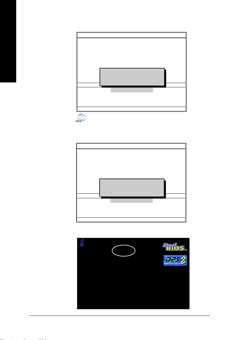
4. Press any keys to return to the Q-Flash menu when the BIOS updating procedure is completed.
English
5. Press Esc and then Y button to exit the Q-Flash utility. The computer will restart automatically after
you exit Q-Flash.
Boot From......................................... Main Bios
Main ROM Type/Size.............................SST 49LF003A 512K
Backup ROM Type/Size.........................SST 49LF003A 512K
Wide Range Protection Disable
Copy Main ROM Data to Backup
Enter : Run KL:Move ESC:Reset F10:Power Off
Dual BIOS Utility
Boot From Main Bios
Auto Recovery Enable
Halt On Error Disable
!! Copy BIOS completed - Pass !!
Load Default Settings
Please press any key to continue
Save Settings to CMOS
Q-Flash Utility
Load Main BIOS from Floppy
Load Backup BIOS from Floppy
Save Main BIOS to Floppy
Save Backup BIOS to Floppy
You can repeat Step 1 to 4 to flash the backup BIOS, too.
Boot From......................................... Main Bios
Main ROM Type/Size.............................SST 49LF003A 512K
Backup ROM Type/Size.........................SST 49LF003A 512K
Wide Range Protection Disable
Copy Main ROM Data to Backup
Enter : Run KL:Move ESC:Reset F10:Power Off
Dual BIOS Utility
Boot From Main Bios
Auto Recovery Enable
Halt On Error Disable
Are you sure to RESET ?
Load Default Settings
[Enter] to continure or [Esc] to abort...
Save Settings to CMOS
Q-Flash Utility
Load Main BIOS from Floppy
Load Backup BIOS from Floppy
Save Main BIOS to Floppy
Save Backup BIOS to Floppy
After system reboots, you may find the BIOS version on your boot screen becomes the one you flashed.
Award Modular BIOS v6.00PG, An Energy Star Ally
Copyright (C) 1984-2003, Award Software, Inc.
Intel i875P AGPset BIOS for 8KNXP Ultra Fba
The BIOS file becomes
Fab after updating
Check System Health OK , VCore = 1.5250
Main Processor : Intel Pentium(R) 4 1.6GHz (133x12)
<CPUID : 0F27 Patch ID : 0027>
Memory Testing : 131072K OK
Memory Frequency 266 MHz in Single Channel
Primary Master : FUJITSU MPE3170AT ED-03-08
Primary Slave : None
Secondary Master : CREATIVEDVD-RM DVD1242E BC101
Secondary Slave : None
Press DEL to enter SETUP / Dual BIOS / Q-Flash / F9 For Xpress Recovery
09/23/2003-i875P-6A79BG03C-00
- 60 -GA-8IPE775 Series Motherboard
Page 65
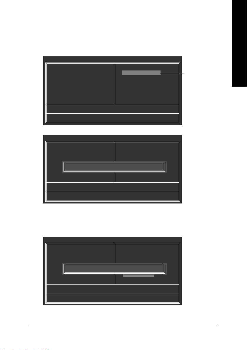
6. Press Del to enter BIOS menu after system reboots. When you are in BIOS menu, move to Load
Fail-Safe Defaults item and press Enter to load BIOS Fail-Safe Defaults. Normally the system
redetects all devices after BIOS has been upgraded. Therefore, we highly recommend reloading the
BIOS defaults after BIOS has been upgraded.
CMOS Setup Utility-Copyright (C) 1984-2003 Award Software
` Standard CMOS Features
` Advanced BIOS Features
` Integrated Peripherals
` Power Management Setup
` PnP/PCI Configurations
` PC Health Status
` Frequency/Voltage Control
ESC: Quit KLJI: Select Item
F8: Dual BIOS/Q-Flash F10: Save & Exit Setup
Load Fail-Safe Defaults (Y/N)? Y
Top Performance
Load Fail-Safe Defaults
Load Optimized Defaults
Set Supervisor Password
Set User Password
Save & Exit Setup
Exit Without Saving
Top Performance
Load Fail-Safe Defaults
Load Optimized Defaults
Set Supervisor Password
Set User Password
Save & Exit Setup
Exit Without Saving
Press Enter on
your keyboard
Press Y on your
keyboard to
load defaults.
English
7. Select Save & Exit Setup item to save the settings to CMOS and exit the BIOS menu.
System will reboot after you exit the BIOS menu. The procedure is completed.
CMOS Setup Utility-Copyright (C) 1984-2003 Award Software
` Standard CMOS Features
` Advanced BIOS Features
` Integrated Peripherals
` Power Management Setup
` PnP/PCI Configurations
` PC Health Status
` Frequency/Voltage Control
ESC: Quit KLJI: Select Item
F8: Dual BIOS/Q-Flash F10: Save & Exit Setup
Save to CMOS and EXIT (Y/N)? Y
Top Performance
Load Fail-Safe Defaults
Load Optimized Defaults
Set Supervisor Password
Set User Password
Save & Exit Setup
Exit Without Saving
- 61 -
Press Y on your
keyboard to
save and exit.
Technical Reference
Page 66
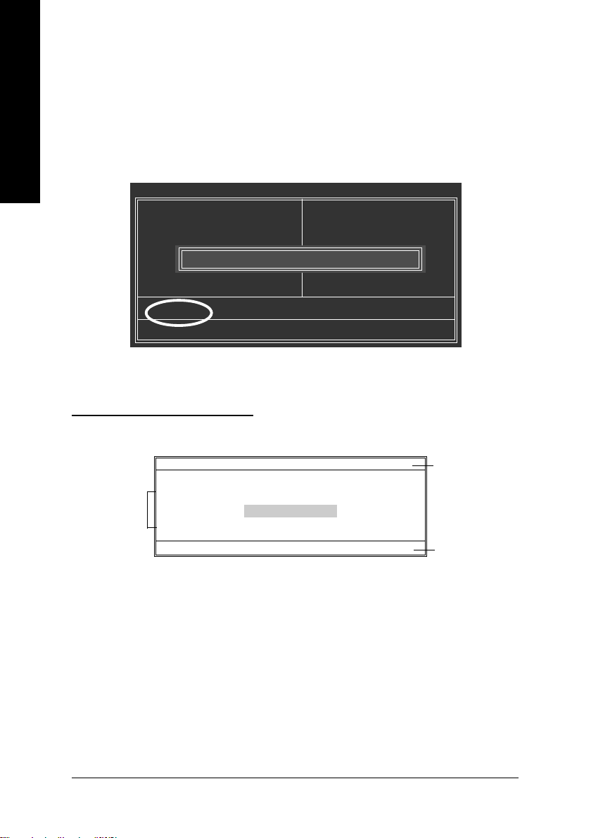
Part Two:
Updating BIOS with Q-Flash
This part guides users of single-BIOS motherboards how to update BIOS using the Q-Flash™ utility.
TM
Utility on Single-BIOS Motherboards.
English
Entering the Q-FlashTM utility:
Step1: To use the Q-Flash utility, you must press Del in the boot screen to enter BIOS menu.
Step 2: Press F8 button on your keyboard and then Y button to enter the Q-Flash utility.
Exploring the Q-FlashTM utility screen
The Q-FlashBIOS utility screen consists of the following key components.
Task menu for
Q-FlashTM utility
CMOS Setup Utility-Copyright (C) 1984-2003 Award Software
` Standard CMOS Features
` Advanced BIOS Features
` Integrated Peripherals
` Power Management Setup
` PnP/PCI Configurations
` PC Health Status
` Frequency/Voltage Control
ESC: Quit KLJI: Select Item
F8: Q-Flash F10: Save & Exit Setup
Flash Type/Size.............................. SST 49LF003A 256K
Enter : Run KL:Move ESC:Reset F10:Power Off
Enter Q-Flash Utility (Y/N)? Y
Q-Flash Utility V1.30
Keep DMI Data Enable
Update BIOS from Floppy
Save BIOS to Floppy
Top Performance
Load Fail-Safe Defaults
Load Optimized Defaults
Set Supervisor Password
Set User Password
Save & Exit Setup
Exit Without Saving
Q-FlashTM utility bar
Action bar
Task menu for Q-Flash utility:
Contains the names of three tasks. Blocking a task and pressing Enter key on your keyboard to enable
execution of the task.
Action bar:
Contains the names of four actions needed to operate the Q-Flash utility. Pressing the buttons mentioned
on your keyboards to perform these actions.
- 62 -GA-8IPE775 Series Motherboard
Page 67
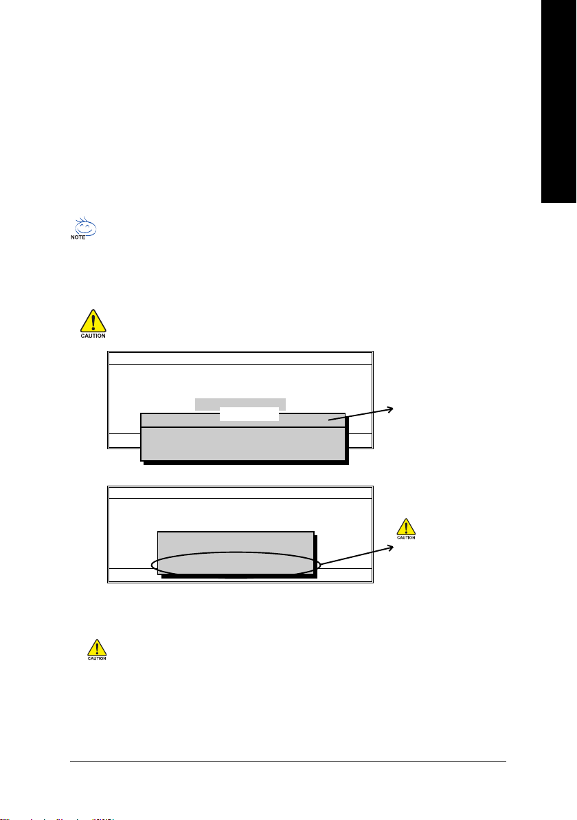
Using the Q-FlashTM utility:
This section tells you how to update BIOS using the Q-Flash utility. As described in the "Before you begin"
section above, you must prepare a floppy disk having the BIOS file for your motherboard and insert it to
your computer. If you have already put the floppy disk into your system and have entered the Q-Flash
utility, please follow the steps below to flash BIOS.
Steps:
1. Press arrow buttons on your keyboard to move the light bar to "Update BIOS from Floppy" item in the
Q-Flash menu and press Enter button.
Later, you will see a box pop up showing the BIOS files you previously downloaded to the floppy disk.
If you want to save the current BIOS for backup purpose, you can begin Step 1 with "Save BIOS
to Floppy" item.
2. Move to the BIOS file you want to flash and press Enter.
In this example, we only download one BIOS file to the floppy disk so only one BIOS file,
8GE800.F4, is listed.
Please confirm again you have the correct BIOS file for your motherboard.
English
Flash Type/Size.............................. SST 49LF003A 256K
8GE800.F4 256K
Enter : Run KL:Move ESC:Reset F10:Power Off
Total size: 1.39M Free size:1.14M
F5 : Refresh DEL : Delete
Flash Type/Size.............................. SST 49LF003A 256K
Reading BIOS file from floppy...
>>>>>>>>>>>>......................
Enter : Run KL:Move ESC:Reset F10:Power Off
Don't Turn Off Power Or Reset System
Q-Flash Utility V1.30
Keep DMI Data Enable
Update BIOS from Floppy
1 file(s) found
Save BIOS to Floppy
Q-Flash Utility V1.30
Keep DMI Data Enable
Update BIOS from Floppy
Save BIOS to Floppy
BIOS file in the floppy disk.
Do not trun off power or
reset your system at this
stage!!
After BIOS file is read, you'll see a confirmation dialog box asking you "Are you sure to update BIOS?"
Please do not take out the floppy disk when it begins flashing BIOS.
- 63 -
Technical Reference
Page 68
3. Press Y button on your keyboard after you are sure to update BIOS.
Then it will begin to update BIOS. The progress of updating BIOS will be shown at the same time.
English
4. Press any keys to return to the Q-Flash menu when the BIOS updating procedure is completed.
5. Press Esc and then Y button to exit the Q-Flash utility. The computer will restart automatically after
Flash Type/Size.............................. SST 49LF003A 256K
Enter : Run KL:Move ESC:Reset F10:Power Off
Flash Type/Size.............................. SST 49LF003A 256K
Enter : Run KL:Move ESC:Reset F10:Power Off
Don't Turn Off Power Or Reset System
Q-Flash Utility V1.30
Keep DMI Data Enable
Updating BIOS Now...
Update BIOS from Floppy
>>>>>>>>>>>>>>........................
Save BIOS to Floppy
Q-Flash Utility V1.30
Keep DMI Data Enable
Update BIOS from Floppy
!! Copy BIOS completed - Pass !!
Save BIOS to Floppy
Please press any key to continue..........
you exit Q-Flash.
Flash Type/Size.............................. SST 49LF003A 256K
Enter : Run KL:Move ESC:Reset F10:Power Off
Q-Flash Utility V1.30
Keep DMI Data Enable
Update BIOS from Floppy
Are you sure to RESET ?
Save BIOS to Floppy
[Enter] to continure or [Esc] to abort...
The porcess of updating
BIOS
Do not trun off power or
reset your system at this
stage!!
After system reboots, you may find the BIOS version on your boot screen becomes the one you flashed.
Award Modular BIOS v6.00PG, An Energy Star Ally
Copyright (C) 1984-2003, Award Software, Inc.
The BIOS file becomes
Fab after updating
Intel 845GE AGPSet BIOS for 8GE800 F4
Check System Health OK
Main Processor : Intel Pentium(R) 4 1.7GHz (100x17.0)
<CPUID : 0F0A Patch ID : 0009>
Memory Testing : 122880K OK + 8192K Shared Memory
Primary Master : FUJITSU MPE3170AT ED-03-08
Primary Slave : None
Secondary Master : CREATIVEDVD-RM DVD1242E BC101
Secondary Slave : None
Press DEL to enter SETUP / Q-Flash
03/18/2003-I845GE-6A69YG01C-00
6. Press Del to enter BIOS menu after system reboots and "Load BIOS Fail-Safe Defaults". See how
to Load BIOS Fail-Safe Defaults, please kindly refer to Step 6 to 7 in Part One.
Congratulation!! You have updated BIOS successfully!!
- 64 -GA-8IPE775 Series Motherboard
Page 69
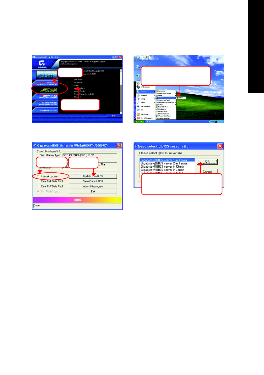
Method 2: @ BIOS Utility
If you don't have DOS boot disk, we recommend that you used Gigabyte @BIOS
flash BIOS.
TM
program to
English
Press here.
1.Click "@BIOS"
(1)
3.Click "".
4.Click here.
(3)
Methods and steps:
I. Update BIOS through Internet
a. Click "Internet Update" icon
b. Click "Update New BIOS" icon
c. Select @BIOS
TM
sever
d. Select the exact model name on your motherboard
e. System will automatically download and update the BIOS.
2.Click"Start"-"Programs"-
"GIGABYTE"-"@BIOS"
(2)
5. Please select @BIOS sever site,
then Click "OK".
(4)
- 65 -
Technical Reference
Page 70

II. Update BIOS NOT through Internet:
English
III. Save BIOS
current BIOS version.
IV. Check out supported motherboard and Flash ROM:
out which kind of motherboard and which brand of Flash ROM are supported.
Note:
a. Do not click "Internet Update" icon
b. Click "Update New BIOS"
c. Please select "All Files" in dialog box while opening the old file.
d. Please search for BIOS unzip file, downloading from internet or any other methods (such as:
8IPE775 Pro.D4).
e. Complete update process following the instruction.
In the very beginning, there is "Save Current BIOS" icon shown in dialog box. It means to save the
In the very beginning, there is "About this program" icon shown in dialog box. It can help you check
a. In method I, if it shows two or more motherboard's model names to be selected, please make
sure your motherboard's model name again. Selecting wrong model name will cause the
system unbooted.
b. In method II, be sure that motherboard's model name in BIOS unzip file are the same as your
motherboard's. Otherwise, your system won't boot.
c. In method I, if the BIOS file you need cannot be found in @BIOS
Gigabyte's web site for downloading and updating it according to method II.
d. Please note that any interruption during updating will cause system unbooted
TM
server, please go onto
- 66 -GA-8IPE775 Series Motherboard
Page 71
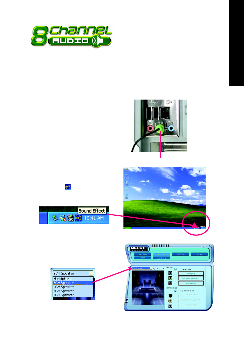
2- / 4- / 6- / 8- Channel Audio
Function Introduction
The installation of windows 98SE/2K/ME/XP is very simple. Please follow next step to install the
function!
Stereo Speakers Connection and Settings:
We recommend that you use the speaker with amplifier to acqiire the best sound effect if the stereo output
is applied.
STEP 1:
Connect the stereo speakers or earphone to "Line
Out".
Line Out
STEP 2 :
Following installation of the audio driver, you find a
icon a Sound Effect icon on the lower right hand
taskbar. Click the icon to select the function.
English
STEP 3:
Click "Speaker Configuration" then click on the left
selection bar and select "2CH Speaker" to com-
plete 2 channel audio configuration.
- 67 -
Technical Reference
Page 72
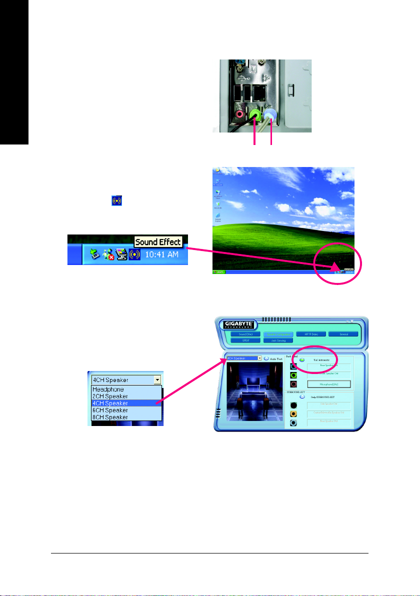
4 Channel Analog Audio Output Mode
STEP 1 :
Connect the front channels to "Line Out",
English
the rear channels to "Line In".
STEP 2 :
Following installation of the audio driver, you find a
icon a Sound Effect icon on the lower right hand
taskbar. Click the icon to select the function.
STEP 3 :
Click "Speaker Configuration" and select the "UAJ
Function". Then click on the left selection bar and
select "4CH Speaker" to complete 4 channel audio
configuration.
Line Out Line In
- 68 -GA-8IPE775 Series Motherboard
Page 73
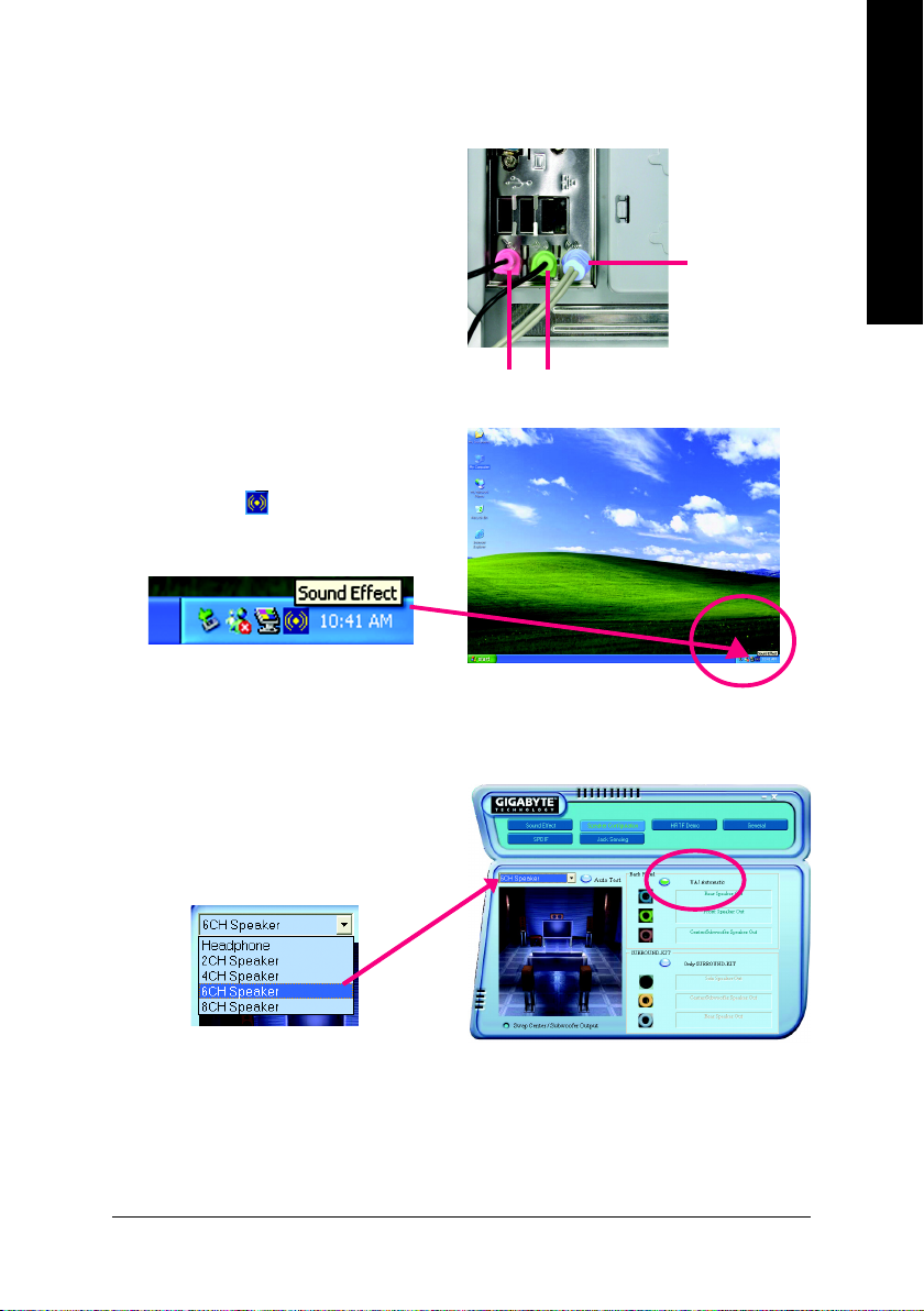
Basic 6 Channel Analog Audio Output Mode
Use the back audio panel to connect the audio out-
put without any additional module.
STEP 1 :
Connect the front channels to "Line Out", the rear
channels to "Line In", and the Center/Subwoofer
channels to "MIC In".
English
Line In
STEP 2 :
Following installation of the audio driver, you find a
icon a Sound Effect icon on the lower right hand
taskbar. Click the icon to select the function.
STEP 3 :
Click "Speaker Configuration" and select the "UAJ
Function". Then click on the left selection bar and
select "6CH Speaker" to complete 6 channel audio
configuration.
MIC In
Line Out
- 69 -
Technical Reference
Page 74

8 Channel Audio Setup (using Audio Combo Kit, Optional Device):
(Audio Combo Kit offers SPDIF output, an optical
English
and coaxial cable and a Surround-Kit. The
Surround-Kit offers R/L surround, center/subwoofer
output and rear surround)
STEP 1 :
Secure the Audio Combo Kit at the panel on the
back of the case.
STEP 2 :
Connect the Surround-Kit to the SUR_CEN connector located on the motherboard.
STEP 3 :
There are two methods of 8 channel audio
configuration:
Method 1:
Connect the front channels to the "LINE OUT"
port located on the audio panel and the rear chan-
nels to the Surround-Kit "REAR R/L" port. Con-
nect the center/subwoofer channels to the Sur-
round-Kit "SUB CENTER" and the R/L channels
to the Surround-Kit "SUR BACK" port.
- 70 -GA-8IPE775 Series Motherboard
Page 75

Method 2:
Connect the front channels to the "LINE OUT"
port located on the audio panel and the rear chan-
nels to the "LINE IN" port. Connect the center/
subwoofer channels to the "MIC IN" port located
on the audio panel and the R/L channels to the
Surround-Kit "SUR BACK" port. (This method
requires UAJ function)
STEP 4 :
Following installation of the audio driver, you find a
icon a Sound Effect icon on the lower right hand
taskbar. Click the icon to select the function.
STEP 5 :
Click "Speaker Configuration" and select both the
"UAJ Function" and "Only Surround-Kit". Then
click on the left selection bar and select "8CH
Speaker" to complete 8 channel audio configuration.
English
Sound Effect Configuration:
At the sound effect menu, users can adjust
sound option settings as desired.
- 71 -
Technical Reference
Page 76

SPDIF Output Device (Optional Device)
A "SPDIF output" device is available on the
English
motherboard. Cable with rear bracket is provided
and could link to the "SPDIF output" connector (As
picture.) For the further linkage to decoder, rear
bracket provides coaxial cable and Fiber
connecting port.
1. Connect the SPDIF output device to the rear
2. Connect SPDIF device to the motherboard.
bracket of PC, and fix it with screw.
3. Connect SPDIF to the SPDIF decoder.
- 72 -GA-8IPE775 Series Motherboard
Page 77

Jack-Sensing and UAJ Introduction
Jack-Sensing provides audio connectors error-detection function.
Install Microsoft DirectX8.1 or later version before to enable Jack-Sensing support for Windows
98/98SE/2000/ME.
Jack-Sensing includes 2 parts: AUTO and MANUAL. Following is an example for 2 channels (Windows
XP):
Introduction of audio connectors
You may connect CDROM, Walkman or others
audio input devices to Line In jack, speakers, ear-
phone or others output devices to Line Out jack,
and microphone to MIC In jack.
English
Auto-detecting:
Please connect the devices to the right jacks
as above. A window will appear as right pic-
ture if you setup the devices properly.
Please note that 3D audio function will only
appear when 3D audio inputs.
- 73 -
Technical Reference
Page 78

If you set wrong with the connectors, the warning
message will come out as right picture.
English
Manual setting:
If the device picture shows different from what you
set, please press "Manual Selection" to set.
UAJ Introduction
UAJ (Universal Audio Jack) has a very smart feature: It will switch signal automatically when user
plugs his audio device to the wrong jack (Line-in/ Line-out). That means users do not need to worry the
audio device should be plug in Line-in or Line-out jack, the device will work perfectly after UAJ is
activated.
Enable UAJ function:
You can click "UAJ Automatic" button to enable
UAJ function.
- 74 -GA-8IPE775 Series Motherboard
Page 79

Xpress Recovery2 Introduction
Xpress Recovery2 is designed to provide quick backup and restoration of hard disk data. Supporting Microsoft operating systems including
Windows XP/2000/NT/98/Me and DOS, and file systems including
FAT16, FAT32, and NTFS, Xpress Recovery2 is able to back up data
on hard disks on PATA and SATA IDE controllers. After Xpress Recovery2 is executed from CD-ROM
for the first time, it will stay permanent in your hard disk. If you wish to run Xpress Recovery2 later, you
can simply press F9 during system bootup to enter Xpress Recovery2 without the CD-ROM.
System requirements:
1. Intel x86 platforms
2. At least 64M bytes of system memory
3. VESA-supported VGA cards
How to use the Xpress Recovery2
Initial access by booting from CD-ROM and subsequent access by pressing the F9 key:
Steps: After entering BIOS Setup, go to Advanced BIOS Feature and set to boot from CD-ROM. Save
the settings and exit the BIOS Setup. Insert the provided driver CD into your CD-ROM drive. Upon
system restart, the message which says "Boot from CD/DVD:" will appear in the bottom left corner
of the screen. Press any key to enter Xpress Recovery2.
After the steps above are completed, subsequent access to Xpress Recovery2 can be made
by simply pressing the <F9> key during system power-on.
.
.
Boot from CD/DVD:
Press any key to startup XpressRecovery2.....
Award Modular BIOS v6.00PG, An Energy Star Ally
Copyright (C) 1984-2004, Award Software, Inc.
Intel 945 BIOS for 8I945GME E7
.
.
.
.
<DEL>:BIOS Setup/Q-Flash, <F9>: Xpress Recovery2
11/07/2005-I945-6A79HG0GC-00
Boot from CD/DVD:
<F9> Xpress Recovery2
English
1. If you have already entered Xpress Recovery2 by booting from the CD-ROM, you can
enter Xpress Recovery2 by pressing the <F9> key in the future.
2. System storage capacity and the reading/writing speed of the hard disk will affect
the data backup speed.
3. It is recommended that Xpress Recovery2 be immediately installed once you complete installations of OS and all required drivers as well as software.
- 75 -
Technical Reference
Page 80

The Main Screen of Xpress Recovery2
English
Limitations:
1. Not compatible to Xpress Recovery.
2. For the use of Xpress Recovery2, a primary partition must be reserved.
3. Xpress Recovery2 will store the backup file at the end of the hard disk, so free space available
4. Capable of backing up hard disks installed with Windows operating systems including DOS and
5. USB hard disks are currently not supported.
6. Does not support RAID/AHCI (class code 0104/0106) hard disks.
7. Capable of backing up and restoring only the first physical hard disk.
Hard disks detection sequence is as follows:
Precautions:
1. When using hard disks with more than 128G under Windows 2000, be sure to execute the
2. It is normal that data backup takes longer time than data restoration.
3. Xpress Recovery2 is compliant with the GPL regulations.
4. On a few motherboards based on Nvidia chipsets, BIOS update is required for Xpress Recovery2
5. Xpress Recovery2 supports only PATA hard disks and not SATA hard disks on the following
1. RESTORE:
Restore the backed-up data to your hard disk.
(This button will not appear if there is no backup
file.)
2. BACKUP:
Back up data from hard disk.
3. REMOVE:
Remove previously-created backup files
to release disk space.
(This button will not appear if there is no backup
file.)
4. REBOOT:
Exit the main screen and restart the system.
on the hard disk for the backup file must be allocated in advance. (A minimum 4GB is recommended but the actual space is dependent on the size of the data to be backed up)
Windows XP/2000/NT/9x/Me.
a. PATA IDE primary channel
b. PATA IDE secondary channel
c. SATA IDE channel 1
d. SATA IDE channel 2
e. SATA IDE channel 3
f. SATA IDE channel 4
EnableBigLba.exe program from the driver CD before data backup.
to correctly identify RAID and SATA IDE mode. Please contact your motherboard manufacturer.
motherboards (As this is a BIOS-related issue, it can be solved by BIOS update)
GA-K8U
GA-K8U-9
GA-K8NXP-SLI
GA-K8N Ultra-SLI
GA-K8N Pro-SLI
GA-K8NXP-9
GA-K8N Ultra-9
GA-K8NF-9 (PCB Ver. 1.0)
GA-K8NE (PCB Ver. 1.0)
GA-K8NMF-9
- 76 -GA-8IPE775 Series Motherboard
GA-8N-SLI Royal
GA-8N-SLI Pro
GA-8N-SLI
Page 81

English
- 77 -
Technical Reference
Page 82

English
- 78 -GA-8IPE775 Series Motherboard
Page 83
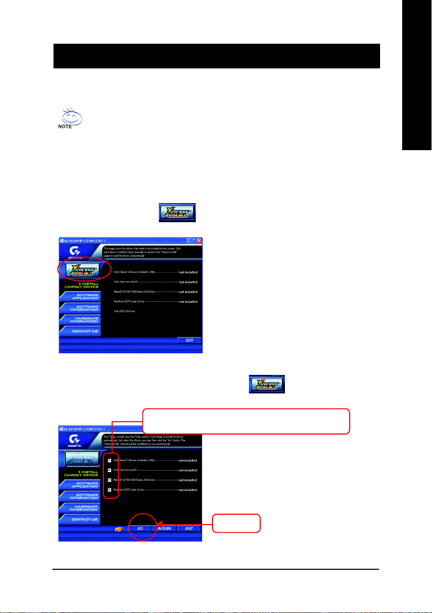
Revision History
Chapter 5 Appendix
Install Drivers
Pictures below are shown in Windows XP
Insert the driver CD-title that came with your motherboard into your CD-ROM drive, the
driver CD-title will auto start and show the installation guide. If not, please double click
the CD-ROM device icon in "My computer", and execute the setup.exe.
INSTALL CHIPSET DRIVER
This page shows the drivers that need to be installed for the system. Click each item to install the
driver manually or switch to the to install the drivers automatically.
Massage: Some device drivers will restart your
system automatically. After restarting your
system the "Xpress Install" will continue to
install other drivers.
English
The "Xpress Install" uses the"Click and Go" technology to install the drivers automatically. Just
select the drivers you want then click the "GO" button. The will execute the installation
for you by itself.
We recommend that you install all components in the list.
Click "GO".
- 79 -
Appendix
Page 84

English
Item Description
Intel Chipset Software Installation Utility
USB Patch for WinXP
Marvell 10/100/1000 Base LAN Driver
RealTek AC97 Codec Driver
Intel USB 2.0 Driver
Driver install finished!! you have to reboot
system!!
Tell the operating system how the chipset components will be configured.
This patch driver can help you to resolve the USB device wake up S3 hang up issue in XP.
For Marvell 10/100/1000 LAN chip use.
For Intel(R) ICH/ICH2/ICH4/ICH5 AC97 audio.
It is recommended that you use the Microsoft Windows update for the most updated driver.
For USB2.0 driver support under Windows XP operating system, please use Windows Service
Pack. After install Windows Service Pack, it will show a question mark "?" in "Universal Serial Bus
controller" under "Device Manager". Please remove the question mark and restart the system
(System will auto-detect the right USB2.0 driver).
Only for GA-8IPE775 Pro.
Only for GA-8IPE775-G.
- 80 -GA-8IPE775 Series Motherboard
Page 85

SOFTWARE APPLICATION
This page reveals the value-added software developed by Gigabyte and its worldwide partners.
Gigabyte Windows Utilities Manager(GWUM)
This utility can integrate the Gigabyte's applications in the system tray.
Gigabyte Management Tool(GMT)
A useful tool which can manage the computer via the network.
EasyTune4
Powerful utility that integrates the overclocking and hardware monitoring functions.
DMI Viewer
Windows based utility which is used to browse the DMI/SMBIOS information of the system.
Face-Wizard
New utility for adding BIOS logo.
@BIOS
Gigabyte windows flash BIOS utility.
Acrobat e-Book
Useful utility from Adobe.
Acrobat Reader
Popular utility from Adobe for reading .PDF file format documents.
Norton Internet Security(NIS)
Integrated utility which includes anti-virus, ad control, etc
DirectX 9
Install Microsoft DirectX 9 to enable 3D hardware acceleration that support for operating
system to achieve better 3D performence.
Marvell VCT Utility
Utility for Marvell chips. [VCT(Virtual Cable Tester) Technology for Gigabit Networks]
English
Only for GA-8IPE775 Pro.
Only for GA-8IPE775-G.
- 81 -
Appendix
Page 86
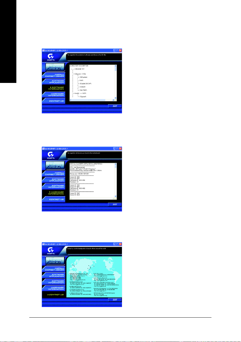
SOFTWARE INFORMATION
This page list the contects of softwares and drivers in this CD title.
English
HARDWARE INFORMATION
This page lists all device you have for this motherboard.
CONTACT US
Please see the last page for details.
- 82 -GA-8IPE775 Series Motherboard
Page 87

FAQ
Below is a collection of general asked questions. To check general asked questions based on a specific
motherboard model, please log on to http://tw.giga-byte.com/faq/faq.htm
Question 1: I cannot see some options that were included in previous BIOS after updating BIOS. Why?
Answer: Some advanced options are hidden in new BIOS version. Please press Ctrl and F1 keys after
entering BIOS menu and you will be able to see these options.
Questions 2: Why is the light of my keyboard/optical mouse still on after computer shuts down?
Answer: In some boards, a small amount of electricity is kept on standby after computer shuts down and
that's why the light is still on.
Question 3: How do I clear CMOS?
Answer: If your board has a Clear CMOS jumper, please refer to the Clear CMOS steps in the manual. If your
board doesn't have such jumper, you can take off the on-board battery to leak voltage to clear CMOS.
Please refer to the steps below:
Steps:
1. Turn off power.
2. Disconnect the power cord from MB.
3. Take out the battery gently and put it aside for about 10 minutes (Or you can use a metal object to
connect the positive and negative pins in the battery holder to makethem short for one minute).
4. Re-insert the battery to the battery holder.
5. Connect power cord to MB again and turn on power.
6. Press Del to enter BIOS and load Fail-Safe Defaults.
7. Save changes and reboot the system.
Question 4: Why does system seem unstable after updating BIOS?
Answer: Please remember to load Fail-Safe Defaults (Or Load BIOS Defaults) after flashing BIOS. However,
if the system instability still remains, please clear CMOS to solve the problem.
English
Question 5: Why do I still get a weak sound after turning up the speaker to the maximum volume?
Answer: Please make sure the speaker you are using is equipped with an internal amplifier. If not, please
change another speaker with power/amplifier and try again later.
Question 6: How do I disable onboard VGA card in order to add an external VGA card?
Answer: Gigabyte motherboards will auto-detect the external VGA card after it is plugged in, so you don't
need to change any setting manually to disable the onboard VGA.
- 83 -
Appendix
Page 88

Question 7: Why cannot I use the IDE 2?
Answer: Please refer to the user manual and check whether you have connected any cable that is not
provided with the motherboard package to the USB Over Current pin in the Front USB Panel. If the cable is
your own cable, please remove it from this pin and do not connect any of your own cables to it.
English
Question 8: Sometimes I hear different continuous beeps from computer after system boots up. What do
these beeps usually stand for?
Answer: The beep codes below may help you identify the possible computer problems. However, they are
only for reference purposes. The situations might differ from case to case.
AMI BIOS Beep Codes
*
Computer gives 1 short beep when system boots successfully.
*Except for beep code 8, these codes are always fatal.
1 beep Refresh failure
2 beeps Parity error
3 beeps Base 64K memory failure
4 beeps Timer not operational
5 beeps Processor error
6 beeps 8042 - gate A20 failure
7 beeps Processor exception interrupt error
8 beeps Display memory read/write failure
9 beeps ROM checksum error
10 beeps CMOS shutdown register read/write error
11 beeps Cache memory bad
AWARD BIOS Beep Codes
1 short: System boots successfully
2 short: CMOS setting error
1 long 1 short: DRAM or M/B error
1 long 2 short: Monitor or display card error
1 long 3 short: Keyboard error
1 long 9 short: BIOS ROM error
Continuous long beeps: DRAM error
Continuous short beeps: Power error
- 84 -GA-8IPE775 Series Motherboard
Page 89
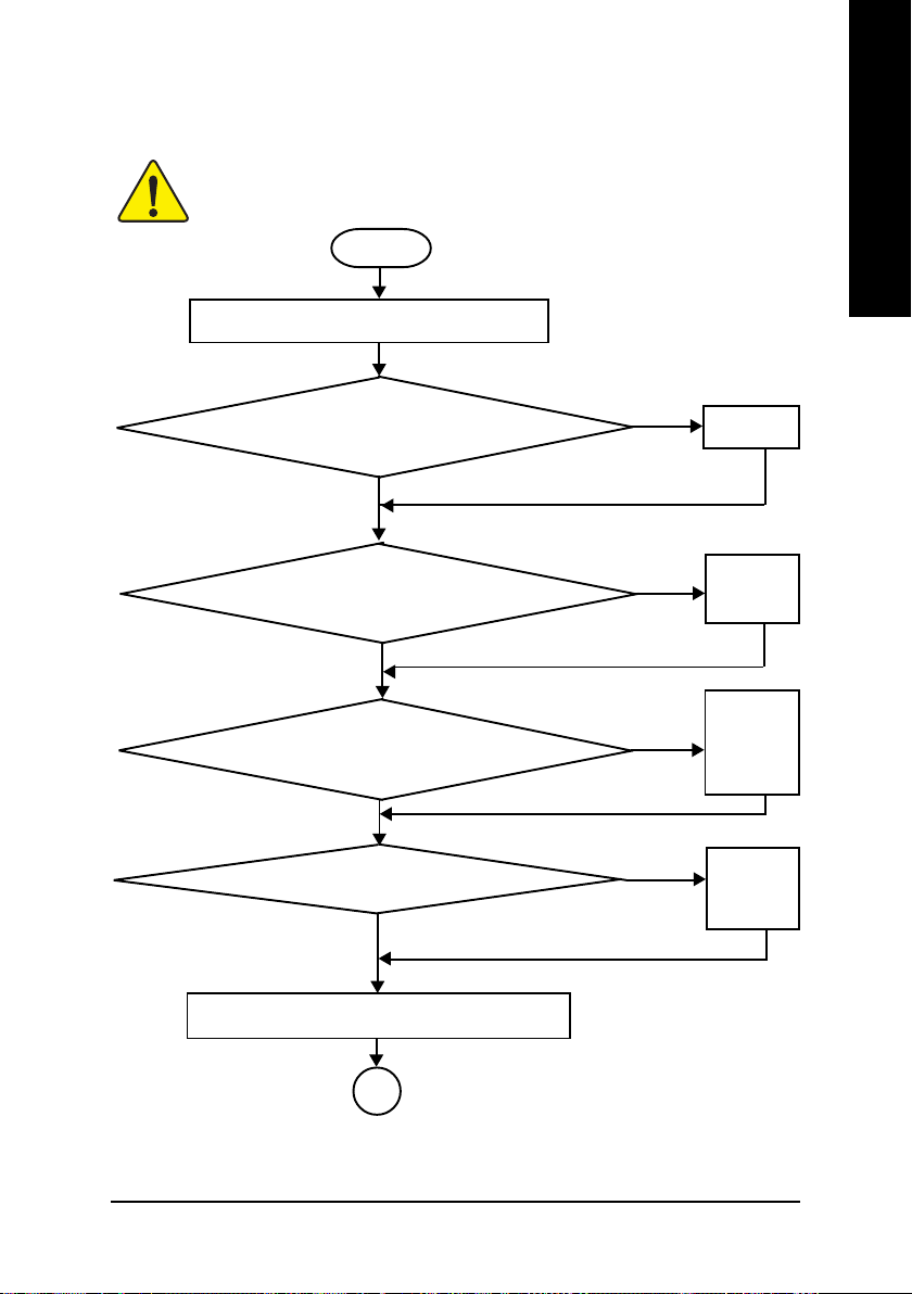
Troubleshooting
If you encounter any trouble during boot up, please follow the troubleshooting
procedures .
Turn off the power and unplug the AC power cable, then
remove all of the add-on cards and cables from motherboard.
Please make sure motherboard & chassis are not short ?
English
START
Yes
Please isolate
the short pin.
No
Failure has been excluded.
Please make sure all jumper settings (such as CPU system bus
speed, frequency ratio, voltage and etc.) are set properly.
Yes
Check if the CPU cooling fan attached to CPU properly. ls
CPU cooling fan power connected to CPU_FAN
properly?
Yes
Check if the memory install properly into the DIMM slot.
Yes
Insert the VGA card. Then plug in ATX power cable and
turn on the system.
A
No
Failure has been excluded.
No
Failure has been excluded.
No
Failure has been excluded.
Make sure the
jumper setting
are correct.
Plug the CPU
cooling fan power
in the CPU fan
connector. Plug in
the AC power
connector.
Insert and push
the memory
module vertically
into the DIMM slot.
- 85 -
Appendix
Page 90

English
A
Is memory LED on and CPU fan running?
Yes
The problem could
be caused by
power supply, CPU,
No
memory or CPU/
memory socket
itself.
Failure has been excluded.
Check if there is display.
Yes
Turn off the system. Reboot after keyboard and mouse
have been plugged in.
Check if keyboard is working properly.
Yes
Press <Del> to enter BIOS setup. Choose "Load
Optimized Defaults" and save then exit setup.
Turn off the system and re-connect the IDE cable. Check
if the system can reboot successfully.
Yes
Reinstall Windows OS, and reinstall add-on cards and cables.
Then try to reboot the system.
No
Perhaps your VGA
card / VGA slot or
monitor is defective.
Failure has been excluded.
It is possible that
No
your keyboard or
keyboard connector
is defective.
Failure has been excluded.
No
The problem was
probably caused by
the IDE device /
connector or cable.
Failure has been excluded.
END
If the above procedure unable to solve your problem, please contact with your local retailer or
national distributor for help. Or, you could submit your question to the service mail via Gigabyte
website technical support zone
(http://www.gigabyte.com.tw). The appropriate response will be provided ASAP.
- 86 -GA-8IPE775 Series Motherboard
Page 91

Technical Support/RMA Sheet
Customer/Country: Company: Phone No.:
Contact Person: E-mail Add. :
Model name/Lot Number: PCB revision:
BIOS version: O.S./A.S.:
Hardware Mfs. Model name Size: Driver/Utility:
Configuration
CPU
Memory
Brand
Video Card
Audio Card
HDD
CD-ROM /
DVD-ROM
Modem
Network
AMR / CNR
Keyboard
Mouse
Power supply
Other Device
English
Problem Description:
- 87 -
Appendix
Page 92

Acronyms
Acronyms Meaning
English
ACPI Advanced Configuration and Power Interface
APM Advanced Power Management
AGP Accelerated Graphics Port
AMR Audio Modem Riser
ACR Advanced Communications Riser
BIOS Basic Input / Output System
CPU Central Processing Unit
CMOS Complementary Metal Oxide Semiconductor
CRIMM Continuity RIMM
CNR Communication and Networking Riser
DMA Direct Memory Access
DMI Desktop Management Interface
DIMM Dual Inline Memory Module
DRM Dual Retention Mechanism
DRAM Dynamic Random Access Memory
DDR Double Data Rate
ECP Extended Capabilities Port
ESCD Extended System Configuration Data
ECC Error Checking and Correcting
EMC Electromagnetic Compatibility
EPP Enhanced Parallel Port
ESD Electrostatic Discharge
FDD Floppy Disk Device
FSB Front Side Bus
HDD Hard Disk Device
IDE Integrated Dual Channel Enhanced
IRQ Interrupt Request
to be continued......
- 88 -GA-8IPE775 Series Motherboard
Page 93

Acronyms Meaning
IOAPIC Input Output Advanced Programmable Input Controller
ISA Industry Standard Architecture
LAN Local Area Network
I/O Input / Output
LBA Logical Block Addressing
LED Light Emitting Diode
MHz Megahertz
MIDI Musical Instrument Digital Interface
MTH Memory Translator Hub
MPT Memory Protocol Translator
NIC Network Interface Card
OS Operating System
OEM Original Equipment Manufacturer
PAC PCI A.G.P. Controller
POST Power-On Self Test
PCI Peripheral Component Interconnect
RIMM Rambus in-line Memory Module
SCI Special Circumstance Instructions
SECC Single Edge Contact Cartridge
SRAM Static Random Access Memory
English
- 89 -
Appendix
Page 94

English
- 90 -GA-8IPE775 Series Motherboard
Page 95

Contact Us
English
Taiwan (Headquarters)
GIGA-BYTE TECHNOLOGY CO., LTD.
Address: No.6, Bau Chiang Road, Hsin-Tien, Taipei 231,
Taiwan
TEL: +886-2-8912-4888
FAX: +886-2-8912-4003
Tech. Support :
http://tw.giga-byte.com/TechSupport/ServiceCenter.htm
Non-Tech. Support(Sales/Marketing) :
http://ggts.gigabyte.com.tw/nontech.asp
WEB address (English): http://www.gigabyte.com.tw
WEB address (Chinese): http://chinese.giga-byte.com
U.S.A.
G.B.T. INC.
TEL: +1-626-854-9338
FAX: +1-626-854-9339
Tech. Support :
http://tw.giga-byte.com/TechSupport/ServiceCenter.htm
Non-Tech. Support(Sales/Marketing) :
http://ggts.gigabyte.com.tw/nontech.asp
WEB address : http://www.giga-byte.com
Germany
G.B.T. TECHNOLOGY TRADING GMBH
Tech. Support :
http://tw.giga-byte.com/TechSupport/ServiceCenter.htm
Non-Tech. Support(Sales/Marketing) :
http://ggts.gigabyte.com.tw/nontech.asp
WEB address : http://www.gigabyte.de
Japan
NIPPON GIGA-BYTE CORPORATION
WEB address : http://www.gigabyte.co.jp
Singapore
GIGA-BYTE SINGAPORE PTE. LTD.
Tech. Support :
http://tw.giga-byte.com/TechSupport/ServiceCenter.htm
Non-Tech. Support(Sales/Marketing) :
http://ggts.gigabyte.com.tw/nontech.asp
WEB address: http://www.gigabyte.com.sg
U.K.
G.B.T. TECH. CO., LTD.
Tech. Support :
http://tw.giga-byte.com/TechSupport/ServiceCenter.htm
Non-Tech. Support(Sales/Marketing) :
http://ggts.gigabyte.com.tw/nontech.asp
WEB address : http://uk.giga-byte.com
The Netherlands
GIGA-BYTE TECHNOLOGY B.V.
Tech. Support :
http://tw.giga-byte.com/TechSupport/ServiceCenter.htm
Non-Tech. Support(Sales/Marketing) :
http://ggts.gigabyte.com.tw/nontech.asp
WEB address : http://www.giga-byte.nl
- 91 -
Memo
Page 96

China
NINGBO G.B.T. TECH. TRADING CO., LTD.
Tech. Support :
http://tw.giga-byte.com/TechSupport/ServiceCenter.htm
English
Non-Tech. Support(Sales/Marketing) :
http://ggts.gigabyte.com.tw/nontech.asp
WEB address : http://www.gigabyte.com.cn
Shanghai
TEL: +86-021-63410999
FAX: +86-021-63410100
Beijing
TEL: +86-10-62102838
FAX: +86-10-62102848
Wuhan
TEL: +86-27-87851061
FAX: +86-27-87851330
GuangZhou
TEL: +86-20-87586074
FAX: +86-20-85517843
Chengdu
TEL: +86-28-85236930
FAX: +86-28-85256822
Xian
TEL: +86-29-85531943
FAX: +86-29-85539821
Shenyang
TEL: +86-24-23960918
FAX: +86-24-23960918-809
Australia
GIGABYTE TECHNOLOGY PTY. LTD.
Tech. Support :
http://tw.giga-byte.com/TechSupport/ServiceCenter.htm
Non-Tech. Support(Sales/Marketing) :
http://ggts.gigabyte.com.tw/nontech.asp
WEB address : http://www.giga-byte.com.au
France
GIGABYTE TECHNOLOGY FRANCE S.A.R.L.
Tech. Support :
http://tw.giga-byte.com/TechSupport/ServiceCenter.htm
Non-Tech. Support(Sales/Marketing) :
http://ggts.gigabyte.com.tw/nontech.asp
WEB address : http://www.gigabyte.fr
Russia
Moscow Representative Office Of GIGA-BYTE Technology Co.,
Ltd.
Tech. Support :
http://tw.giga-byte.com/TechSupport/ServiceCenter.htm
Non-Tech. Support(Sales/Marketing) :
http://ggts.gigabyte.com.tw/nontech.asp
WEB address : http://www.gigabyte.ru
Poland
Office of GIGA-BYTE TECHNOLOGY Co., Ltd. in POLAND
Tech. Support :
http://tw.giga-byte.com/TechSupport/ServiceCenter.htm
Non-Tech. Support(Sales/Marketing) :
http://ggts.gigabyte.com.tw/nontech.asp
WEB address : http://www.gigabyte.pl
Serbia & Montenegro
Representative Office Of GIGA-BYTE Technology Co., Ltd. in
SERBIA & MONTENEGRO
Tech. Support :
http://tw.giga-byte.com/TechSupport/ServiceCenter.htm
Non-Tech. Support(Sales/Marketing) :
http://ggts.gigabyte.com.tw/nontech.asp
WEB address: http://www.gigabyte.co.yu
Czech Republic
Representative Office Of GIGA-BYTE Technology Co., Ltd. in
CZECH REPUBLIC
Tech. Support :
http://tw.giga-byte.com/TechSupport/ServiceCenter.htm
Non-Tech. Support(Sales/Marketing) :
http://ggts.gigabyte.com.tw/nontech.asp
WEB address: http://www.gigabyte.cz
Romania
Representative Office Of GIGA-BYTE Technology Co., Ltd. in
Romania
Tech. Support :
http://tw.giga-byte.com/TechSupport/ServiceCenter.htm
Non-Tech. Support(Sales/Marketing) :
http://ggts.gigabyte.com.tw/nontech.asp
WEB address: http://www.gigabyte.com.ro
- 92 -GA-8IPE775 Series Motherboard
 Loading...