

Giantec tracer2000 User Manual

tracer2000
Network Digital Video Recorder
Hardware User’s Manual


Copyright Notice
This document may not, in whole or in part, be reproduced or transmitted in any form
or by means, electronic, mechanical, or optical, including photocopying, recording, or
storing in a retrieval system, or translated into any language in any form wit hout the
prior written notice of agreement from us.
Warranties
We make no warranties with respect to this documentation and disclaim any imp lied
warranties of merchantability and fitness for a particular purpose. We shall not be
liable for any error or for incidental or consequential damages in connection with the
furnishing, performance, or use of this documentation or the examples herein. The
information in this documentation is subject to change without notice.
Trademarks
All other product names mentioned in this documentation are for identification
purposes only and remain the sole property of their respective owners.
Copyright @ 2005 by Giantec Inc.
All Right Reserved.
March 2005, Version 3.1


Giantec Internet Services
Customer satisfaction is our number one concern. To ensure that customers receive the
full benefit of our products, Giantec Internet Services has been set up to provide technical
support, driver updates, product information, and user’ s manual updates . The following
services are provided:
Email for technical support
à Email: service@giantec.com.tw
World Wide Web (WWW) site for product information
à Web Site: http://www.giantec.net


Table of Contents
CHAPTER I INTRODUCTION 1
Limited Warranty 1
Function Introduction 1
Features 2
CHAPTER II PACKAGE 3
CHAPTER III INSTALLATION 4
1. Indicator 5
2. Cable Connection 5
2.1 Connect VGA Monitor .............................................................................. 5
2.2 Connect Camera Cable to BNC Co nnector ................................................... 6
2.3 Connect to LAN Connector: Plug RJ-45 Connector to LAN Port........................ 6
2.4 Connect to Printer Port (Option)................................................................ 7
3. Power Connector 8
3.1 Connect Power Cord (110V ~ 240V Auto Switch) into the Power Socket .......... 8
CHAPTER IV PIN ASSIGNMENT 9
1. Internal Jumpers and Connectors 9
1.1 Power Switch for ATX Power Supply (JP1)..................................................10
1.2 Reset / LED / Speaker (JP1)....................................................................10
1.3 Internal USB Connector (USB2) ...............................................................10
1.4 Power Connector (P1).............................................................................10
1.5 CMOS Clear (J1)....................................................................................10
1.6 COM2 Mode Select (JP3).........................................................................11
1.7 CPU FSB Select (JP4) .............................................................................11
1.8 FAN Control (FAN1, 2)............................................................................11
1.9 HDD Connector (IDE1, 2)........................................................................11
1.10 Parallel / Printer Connector (PR N).............................................................12
1.11 Video Input (J2) ....................................................................................12
1.12 General Purpose Input / Output (J3).........................................................13
1.13 Infra-Red (IR).......................................................................................13
1.14 PCI Bus Pin Assignment..........................................................................14
2. External Connector 15
2.1 CRT Display Connector (VGA) ..................................................................15
2.2 Audio Input Connector............................................................................15
2.3 GPIO Connector.....................................................................................15
2.4 USB Connector......................................................................................15
2.5 COM1 Connector....................................................................................16
2.6 COM2 Connector....................................................................................16
3. Ethernet Connector (RJ-45) 17
3.1 Connector.............................................................................................17

3.2 P/T/Z Setting........................................................................................18
3.3 Pin Assignment of COM2.........................................................................18
3.4 Cable Connection...................................................................................18
3.5 Jumper 3 Setting of COM2.......................................................................18
CHAPTER V CMOS SETTING 19
1. Introduction 19
2. Setup Pages 19
2.1 Standard CMOS Features........................................................................20
2.2 Advanced BIOS Fea tures.........................................................................21
2.3 Advanced Chipset Features......................................................................22
2.4 Integrated Peripherals............................................................................24
2.5 Power Management Setup.......................................................................25
2.6 PnP / PCI Configuration ..........................................................................26
2.7 PC Health Status....................................................................................26
2.8 Frequency / Voltage Control ....................................................................27
2.9 Load Optimized Defaults.........................................................................27
2.10 Supervisor / User Password.....................................................................27
2.11 Save & Exit Setup..................................................................................27
2.12 Exit Without Save..................................................................................27
CHAPTER VI SYSTEM HDD INSTALLATION GUIDE 28

tracer2000 Network DVR Hardware User’s Manual
Chapter I Introduction
Thank you for purchasing tracer2000 DVR; this manual will guide you through the setup,
installation, and use of all our tracer2000 systems.
Before proceeding, please read this manual thoroughly!
If you have any questions or concerns that cannot be solved by following this manual, please
visit our web site at http://www.giantec.net
technical support center at service@giantec.com.tw
Limited Warranty
Giantec Inc. warrants this product to be in compliance with its own plans and specifications.
Moreover, to be free from defects in materials and workmanship under normal use and service
for all parts one year after the original purchase date. During this period Giantec Inc. will
replace parts at no charge, however, labor cost will be laid after one year. Please contact
your dealer / distributor for details.
This warranty excludes damages due to misuse or neglect. Also this warranty does not cover
damages beyond DVR’s control. In no event shall Giantec Inc. be liable for any direct,
indirect or consequential damages; loss of anticipated profits, loss of time or any other l osses
incurred by the buyer in connection with the purchase, installation, operation or failure of this
product. For more details on the limitation of this warranty, contact your distributor.
or for technical issue please contact to our
.
Function Introduction
Thank you for using tracer2000 video surveillance system. tracer can be used to transfer
captured video signal from analog to di gital using the co mpression f ormat for re cord and play.
They can also capture videos of up to 4 / 8 / 16 cameras for model tracer2404 , tracer2408 and
trcer2416 (4 / 8 / 16 BNC inputs) with 4 audio sources at the same time. The built-in video
player makes it easy to play back recorded video files. The system also provides several
control modes like motion detection, schedule record, P/T/Z control and remote surveillance
applications. About detail function describe, please reference tracer2000 software manual.
Version 3.1 Page 1 of 31

tracer2000 Network DVR Hardware User’s Manual
Features
The tracer2000 comes with the following hardware devices:
Control Panel with IR Receiver
One 10/100Mbps TX Fast Ethernet with RJ-45 Connector
One RS232 and one RS232/422/485 Selectable Interface
One VGA (DB-15) Connector
One Speaker Out
One Microphone In
Two USB Ports (USB 1.1 Interface)
Two 3.5” HDD Supported
Four Audio-in Ports
Eight GPIO Ports
Support IR Controller to Remote Control tracer2000
Work ing Temperature: 0°C ~ 40°C
Storage Temperature: -10°C ~ 65°C
Relative Humidity: Maximum 85 % , non-condensing
Power Requirement: AC100 ~ 240V, 50 / 60Hz, 150W Maximum
Dimension: 265mm (D) x 321mm (W) x 103mm (H)
Weight: 5.0kg
Version 3.1 Page 2 of 31

tracer2000 Network DVR Hardware User’s Manual
Chapter II Package
Check the accessories accompany with the system you purchase as listed below. With newer
package release, the accessories are compacted into an accessory box. Please check the
items and contact to your dealer you bought from if any of them is missing.
tracer2000 System
Power Cord
Screws Pack
Remote Contr oller
Battery (AAA) x 2
tracer2000 Software User’s Manual
tracer2000 Hardware User’s Manual
Installat ion CD-ROM
Please keep the packaging materials. You may need them for the use of further service.
Version 3.1 Page 3 of 31
y
k
※
V
p
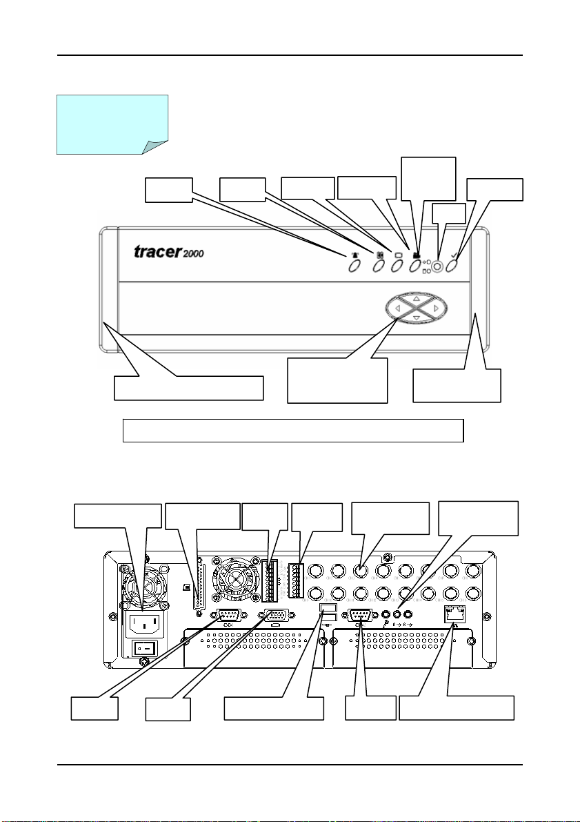
Chapter III Installation
tracer2000 Network DVR Hardware User’s Manual
Powe r Sup ply
COM1
Alarm
Removable Air Filter Bracket
Menu
Displa
LEFT RIGHT
UP
DOWN
Playbac
Remove and clean up Air Filters monthly is essential.
Front Panel View
Parallel Port
GA
GPIO
USB Ports x 2
Audio
BNC
COM2
Rear Panel Vi ew
Power/
HDD
Removable Air
Filter Bracket
10/100 Etherne t Port
MIC and
S
eaker Out
Confirm
Version 3.1 Page 4 of 31
 Loading...