

Page 1
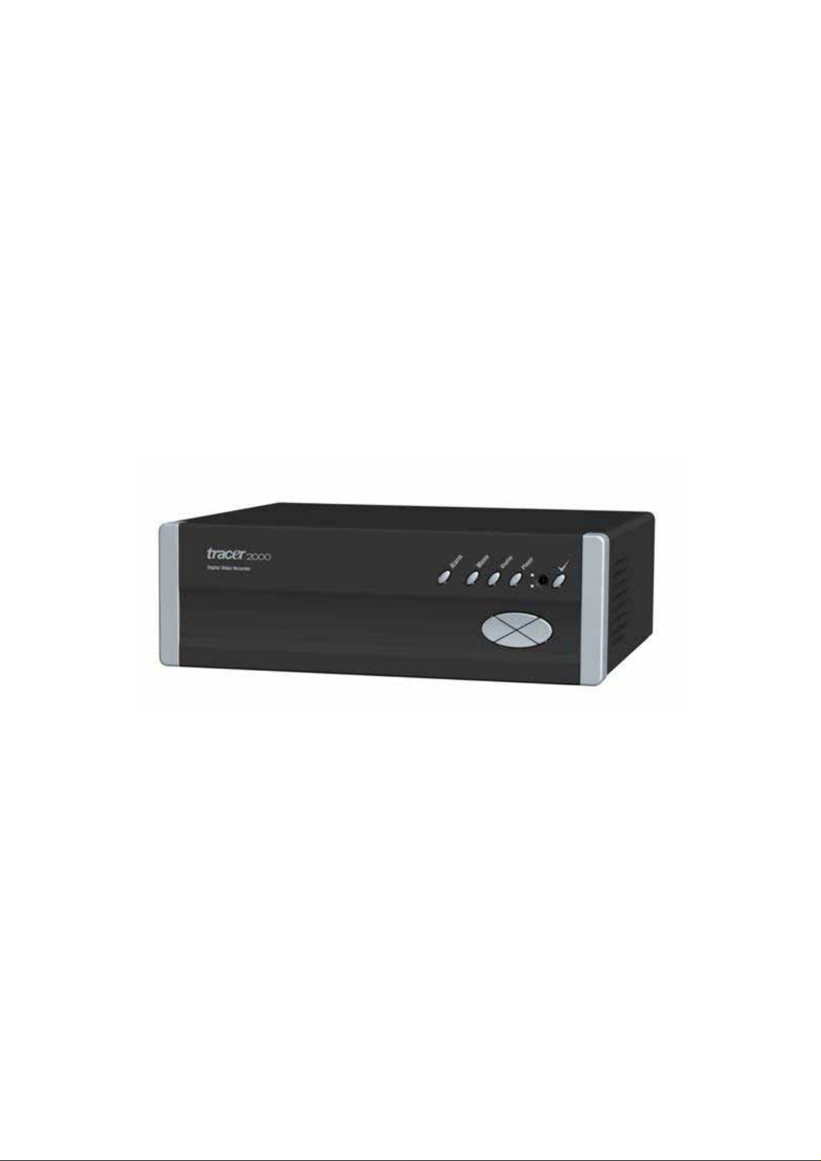
Tracer 2000 Digital Video Recorder
User’s Manual
Page 2

Tracer 2000 DVR user manual
Contents
CHAPTER I INTRODUCTION...............................................................................................................5
LIMITED WARRANTY ...............................................................................................................................5
FUNCTION INTRODUCTION....................................................................................................................5
FEATURE......................................................................................................................................................6
CHAPTER II PACKAGE...........................................................................................................................7
PACKING LIST .................................................................................................................................................7
CHAPTER III INSTALLATION ............................................................................................................8
FRONT PANEL VIEW..................................................................................................................................8
REAR PANEL VIEW....................................................................................................................................8
1 INDICATOR...............................................................................................................................................9
2 CABLE CONNECTION ............................................................................................................................9
2.1. Connect VGA Monitor ........................................................................................................................9
2.2. Connect Camera Cable to BNC connector.......................................................................................10
2.3. Connect to LAN connector: Plug RJ-45 connector to LAN Port......................................................10
3. POWER CONNECTOR..........................................................................................................................12
3.1. Connect power cord (110V~240V auto switch) into the power socket.............................................12
CHAPTER IV PIN ASSIGNMENT......................................................................................................13
NTERNAL JUMPERS AND CONNECTORS.........................................................................................................13
I
EXTERNAL CONNECTOR................................................................................................................................19
CRT DISPLAY CONNECTOR (VGA)...............................................................................................................19
Audio Input connector:............................................................................................................................19
GPIO CONNECTOR:.......................................................................................................................................19
USB connector:........................................................................................................................................19
COM 1 C
ONNECTOR.....................................................................................................................................20
RS-232 Connector (COM1) .....................................................................................................................20
COM2 Connector.....................................................................................................................................20
Connectors...............................................................................................................................................21
P/T/Z Setting ............................................................................................................................................22
CHAPTER V CMOS SETTING..............................................................................................................23
INTRODUCTION .............................................................................................................................................23
SETUP PAGES.................................................................................................................................................23
Version 3.0 Page 2 of 36
Page 3

Tracer 2000 DVR user manual
1. Standard CMOS Features....................................................................................................................24
2. Advanced BIOS Features.....................................................................................................................25
3. Advanced Chipset Features..................................................................................................................26
4. Integrated Peripherals.........................................................................................................................27
5. Power Management Setup ...................................................................................................................28
6. PnP / PCI Configuration .....................................................................................................................29
7. PC Health Status..................................................................................................................................30
8. Frequency/Voltage Control..................................................................................................................30
9. Load Optimized Defaults .....................................................................................................................31
10. Supervisor / User Password...............................................................................................................31
11. Save & Exit Setup...............................................................................................................................31
12. Exit Without Save ...............................................................................................................................31
CHAPTER VI SYSTEM HDD INSTALLATION GUIDE.................................................................32
FOLLOW THE STEP TO SETUP HDD DRAWING BOX.........................................................................................32
1. Remove the screws on the case. (marked in while circles) ..................................................................32
2. Take off the upper cover and remove the screws..................................................................................33
3. Remove HDD Tray, and install HDD properly....................................................................................34
4. Insert the assembled HDD tray into TRACER2000, and connect both Power and HDD cables........35
5. Assemble the upper cover and the screws............................................................................................36
Version 3.0 Page 3 of 36
Page 4

Tracer 2000 DVR user manual
Copyright Notice
Copyright 2004. All Rights Reserved
This document may not, in whole or in part, be reproduced or transmitted in
any form or by means, electronic, mechanical, or optical, including
photocopying, recording, or storing in a retrieval system, or translated into
any language in any form without the prior written content of us.
Warranties
We make no warranties with respect to this documentation and disclaim any
implied warranties of merchantability and fitness for a p articular purpose. W e
shall not be liable for any error or for incidental or consequential damages in
connection with the furnishing, performance, or use of this documentation or
the examples herein.
The information in this documentation is subject to chang e without notice.
T rademarks
All other product names mentioned in this documentation a re for identification
purposes only and remain the sole property of their respectiv e owners.
All Rights Reserved
Version 3.0 Page 4 of 36
Page 5

Tracer 2000 DVR user manual
CHAPTER I INTRODUCTION
Thank you for purchasing Tracer 2000 DVR; this manual will guide you through the setup,
installation, and use of all our DVR systems.
Before proceeding, please read this manual thoroughly!
If you have any questions or concerns that cannot be solved by following this manual, please
visit our web site at http://www.giantec.net
LIMITED WARRANTY
Giantec Inc. warrants this product to be in compliance with its own plans and specifications.
Moreover , to be free from defect s in mater ials and workm anship under norm al use and service
for all parts (1) one year after the original purchase date. During this period Giantec Inc. will
replace parts at no charge, however , labor cost will be laid after one (1) year. Please contact
your dealer/distributor for details.
This warranty excludes damages due to misuse or neglect. Also this warranty does not cover
damages beyond DVR’s control. In no event shall Giante c Inc. be liable for any direct, indirect
or consequential damages; loss of anticipated profits, loss of time or any other losses incurred
by the buyer in connection with the purchase, installation, operation or failure of this product.
For more details on the limitation of this warranty, contact your distributor.
FUNCTION INTRODUCTION
Thank you for using TRACER 2000 video surveillance system. TRACER can be used to
transfer captured video signal from analog to digital using the compression format for record
and play. They can also capture videos of up to 4 / 8 /16 cameras for model TRACER-2404,
TRACER-2408, and TRACER-2416(4 /8/16 BNC input s) with 4 audio sources at the same time.
The built-in video player makes it easy to play back captured video files. The system also
provides several control modes like motion detection, schedule record, P/T/Z control and
remote surveillance applications.
Version 3.0 Page 5 of 36
Page 6

FEATURE
The TRACER2000 comes with the following hardware devices:
Control panel with IR receiver
One10/100Mbps RJ-45 Ethernet Port
One RS 232 and one RS232/422/485 select able interface
One VGA Connector
One speaker out
T wo USB Ports
T wo 3.5” HDD Supported
Four Audio-in Ports
Eight GPIO Ports
Tracer 2000 DVR user manual
Remote Commander
Working temperature: 0 ~ 45 °C
Storage te mperature: -10 ~ 65 °C
Relative humidity: Maximum 85%, non-condensing
Power requirement: AC 100 ~ 240V, 50 / 60 Hz, 150W maximum
Dimension: 265 mm (D) x 321mm (W) x 103mm (H)
Weight: 5Kg
Version 3.0 Page 6 of 36
Page 7

CHAPTER II PACKAGE
Packing List
Check the accessories accompany with the system you purchase as listed below.
With newer package release, the accessories are compacted into an accessory box.
Please check the items and Contact to your dealer you boug ht from if any of them is
missing
Tracer 2000 DVR user manual
TRACER2000 System
Power Cord
Screws Pack
Remote Commander
Battery (AAA) X 2
User’s Manual
Installation CD-ROM
Please keep the packaging materials. You may need them for the use of further service.
Version 3.0 Page 7 of 36
Page 8
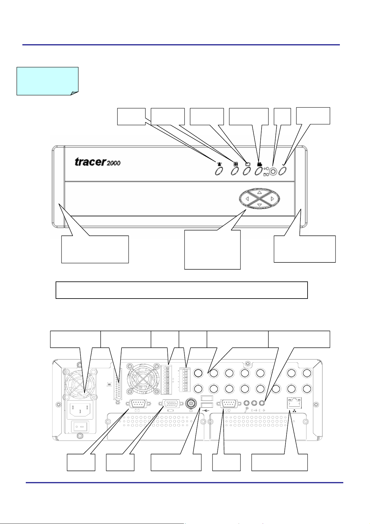
CHAPTER III INSTALLATION
FRONT PANEL VIEW
Tracer 2000 DVR user manual
Alarm Menu
Display
Playback
Removable Air
Filter Bracket
UP
LEFT RIGHT
DOWN
※Remove and clean up Air Filters monthly is essential.
IR
Confirm
Removable Air
Filter Bracket
REAR PANEL VIEW
Power supply
COM1 COM2
Version 3.0 Page 8 of 36
Parallel port BNC connectorGPIO
12
Audio
ALARM OUT
MIC1
4231
MIC2
CH1 CH7
MIC3
ALARM IN
1
MIC4
2
3
4
CH9
CH10
CH3
CH2
CH4 CH5 CH6 CH8
CH11
MIC and Speaker
CH14CH13CH12
CH15
VGA USB Ports x 2 10/100 Ethernet
CH16
Page 9
Tracer 2000 DVR user manual
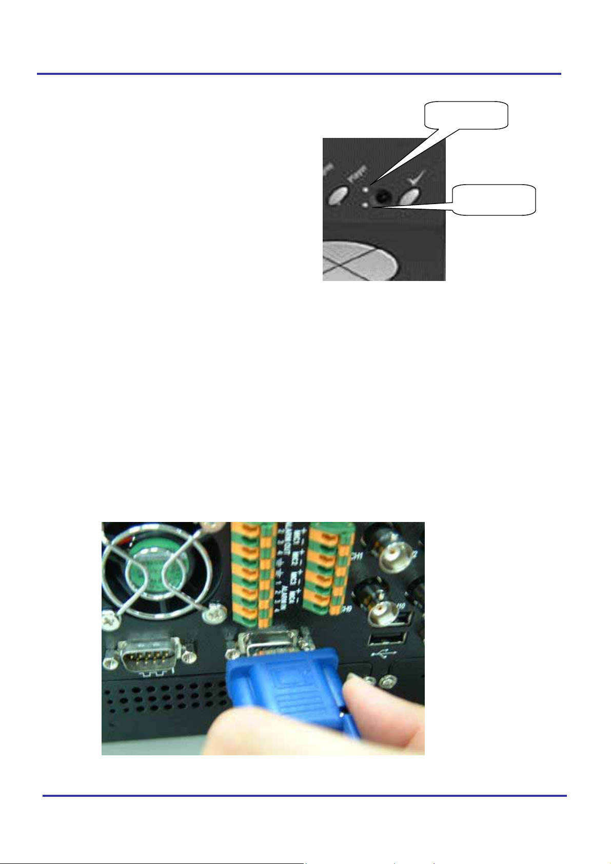
1 INDICATOR
Power LED: Green light shows power is on.
Status LED: Green light continuous on means
working properly.
Green light blinking shows status of recording
Red light continuous on means no signal (This
may implies HDD damaged, No Power, or Access
Error.)
Red light blinking shows status of recycling. (HDD
space less than 1 Gigabyte)
2 CABLE CONNECTION
Following is the basic device must be prepared before to start installation complete system.
1. Tracer 2000
Power LED
Status LED
2. CCD cameras
3. VGA monitor
Please follow the procedure to connect the cable.
2.1. Connect VGA Monitor
Version 3.0 Page 9 of 36
Page 10
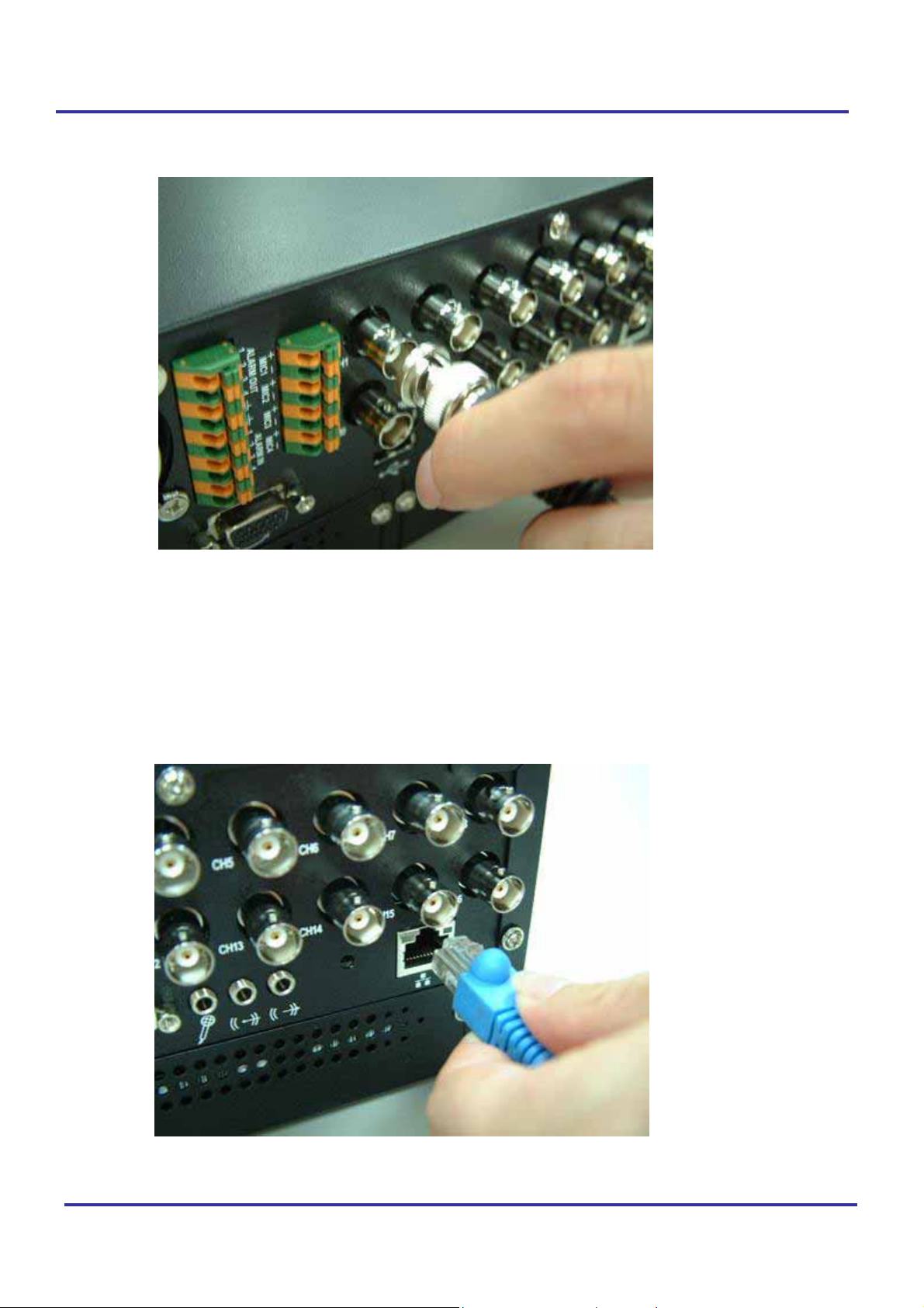
2.2. Connect Camera Cable to BNC connector
Tracer 2000 DVR user manual
2.3. Connect to LAN connector: Plug RJ-45 connector to LAN Port
2.5.1 Insert RJ-45 cable to network LAN socket on the rear.
2.5.2 Connect Serial port modem to serial connector (COM1) and through
Dial-in function to connect to Internet.
Version 3.0 Page 10 of 36
Page 11
Tracer 2000 DVR user manual
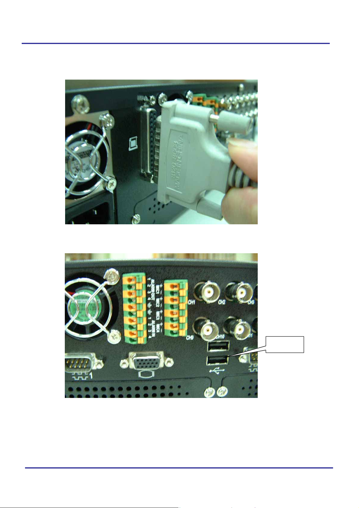
2.4. Connect to Printer Port (option)
There are two types of Printer port. One is LPT the other is USB.
Connect Port as show below:
USB Port
Version 3.0 Page 11 of 36
Page 12
Tracer 2000 DVR user manual
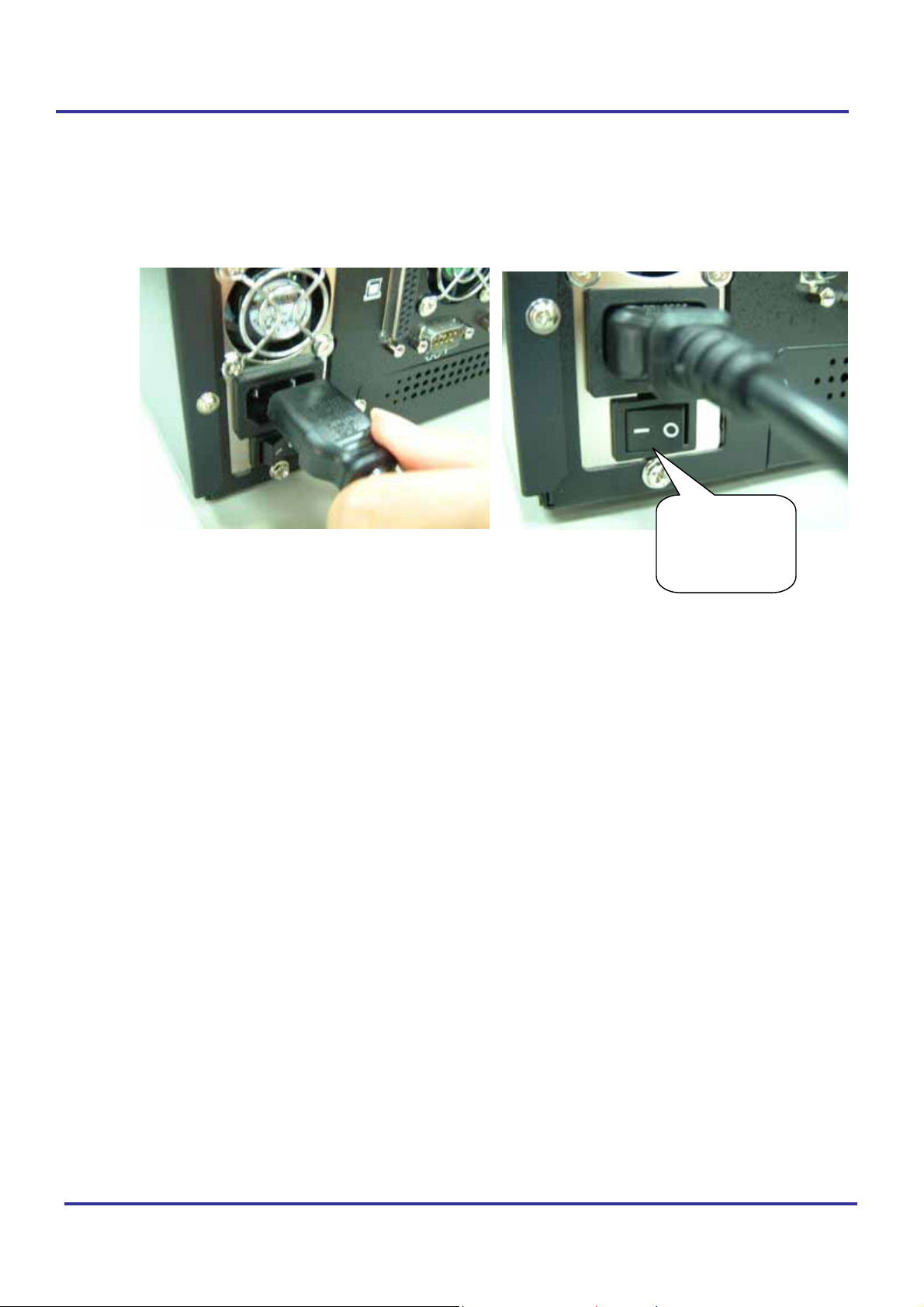
3. POWER CONNECTOR
3.1. Connect power cord (110V~240V auto switch) into the power socket.
Press “I” to start up system...
Pushes switch
“I” to turn it
on.
Version 3.0 Page 12 of 36
Page 13
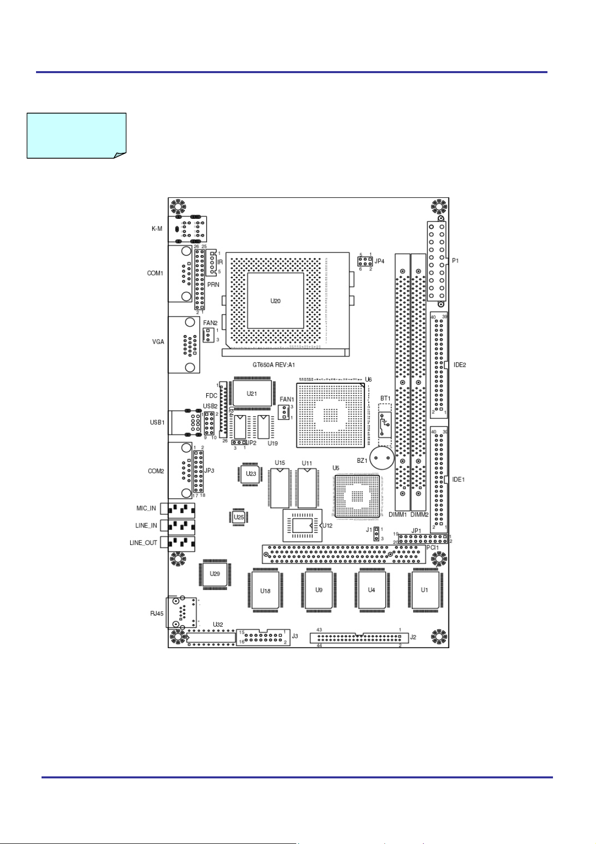
CHAPTER IV Pin assignment
Internal Jumpers and Connectors
Tracer 2000 DVR user manual
Version 3.0 Page 13 of 36
Page 14
Power Switch for ATX power supply (JP1)
Signals JP1
Power ON/OFF 1-3
Reset/LED/Speaker (JP1)
Signals JP1
Power LED, Pin 9+, Pin10- 9-10
External speaker 14-20
HDD LED, Pin8+, Pin7- 7-8
System reset switch 5-6
SUSLED Pin4+, Pin2- 2-4
PS. For the AT system (short pin 10 & pin12) for power on
Internal USB connector (USB2)
Signals USB2-1 USB2-2
Power 1 10
Data - 3 8
Data + 5 6
USB GND 7 4
CHS GND 9 2
Power connector (P1)
Signals P1
+12V 10
+5V 4,6,19,20
-12V 12
-5V 18
+3.3V 1,2,11
5VSB 9
PS-ON 14
POWER-OK 8
Ground 3,5,7,13,15,16,17
CMOS Clear (J1)
J1
POWER OFF and Move jumper from pin 1-2 to pin2-3 of J1,
Reminding POWER OFF 1minute.
Then Move JUMPER back to 1-2 OF J1
COM2 mode Select (JP3)
Mode JP3
RS-232 3-5, 4-6, 9-11, 10-12, 17-18
RS-422 1-3, 2-4, 7-9, 8-10, 15-16
RS-485 1-3, 2-4, 7-9, 8-10, 13-14
Tracer 2000 DVR user manual
Version 3.0 Page 14 of 36
Page 15
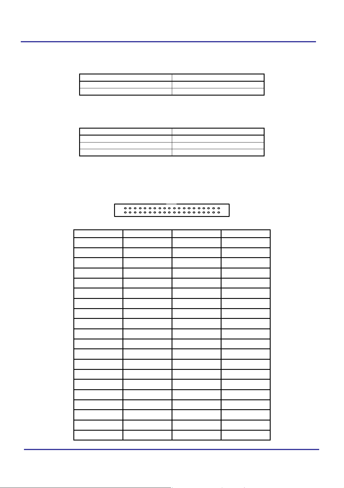
CPU FSB Select (JP4)
FAN control (FAN1, 2)
HDD Connector (IDE1, 2)
Tracer 2000 DVR user manual
Function JP4
Auto by CPU 1-3, 2-4
66 MHz 3-5, 4-6
Function FAN1,2
Sense 3
+12V 2
PWM control 1
39
40
Pin no. Signal Pin no. Signal
1 - RST 2 GND
3 D7 4 D8
5 D6 6 D9
7 D5 8 D10
9 D4 10 D11
11 D3 12 D12
13 D2 14 D13
15 D1 16 D14
17 D0 18 D15
19 GND 20 N.C.
21 N.C. 22 GND
23 IOW 24 GND
25 IOR 26 GND
27 IORDY 28 GND
1
2
29 DACK 30 GND
31 IRQ 32 N.C.
33 A1 34 PDIAG
35 A0 36 A2
37 CS0 38 CS1
39 -ACT 40 GND
Version 3.0 Page 15 of 36
Page 16
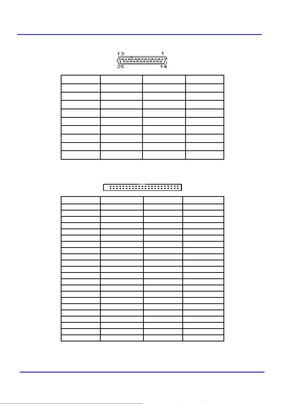
Parallel/Printer connector (PRN)
Tracer 2000 DVR user manual
Video Input (J2)
Pin no. Signal Pin no. Signal
1 Strobe 10 -Acknowledge
2 Data 0 11 Busy
3 Data 1 12 Paper Empty
4 Data 2 13 + Select
5 Data 3 14 - Auto Feed
6 Data 4 15 - Error
7 Data 5 16 - INIT Printer
8 Data 6 17 - Select Input
9 Data 7 18-25 Ground
43
44
Pin no. signals Pin no. signals
1 VCC 2 V-I-OE00
3 GND 4 V-I-OE01
5 VIN00 6 V-I-OE02
7 VIN01 8 V-I-OE03
9 VIN02 10 AGND
11 VIN03 12 V-I-OE30
13 AGND 14 V-I-OE31
15 VIN30 16 V-I-OE32
17 VIN31 18 V-I-OE33
19 VIN32 20 AGND
21 VIN33 22 V-I-OE20
23 AGND 24 V-I-OE21
25 VIN20 26 V-I-OE22
27 VIN21 28 V-I-OE23
29 AGND 30 AGND
31 VIN22 32 V-I-OE10
33 VIN23 34 V-I-OE11
35 AGND 36 V-I-OE12
37 VIN10 38 V-I-OE13
39 VIN11 40 AGND
41 VIN12 42 GND
43 VIN13 44 VCC
1
2
Note: VIN xx is analog video input channel xx.
V-I-OExx is Odd / Even field information of video input channel xx.
Version 3.0 Page 16 of 36
Page 17
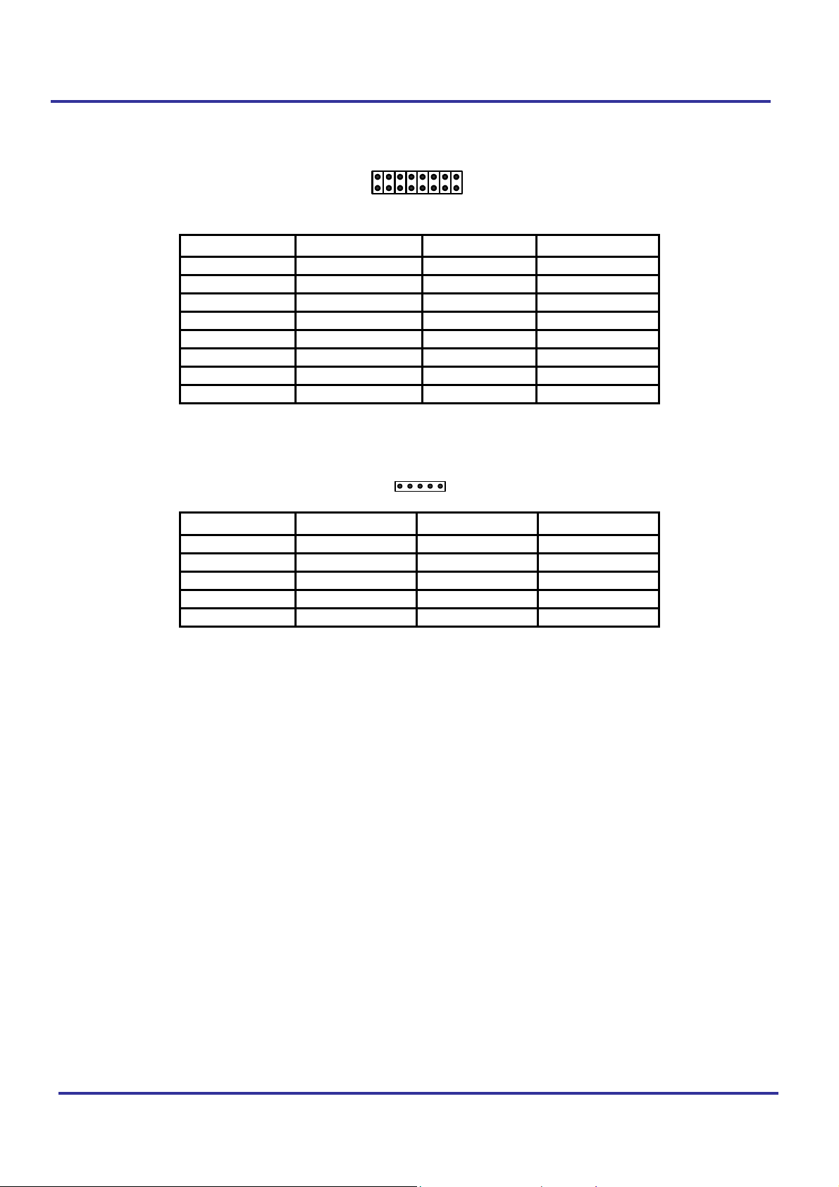
General Purpose Input / Output (J3)
Tracer 2000 DVR user manual
Infra-Red (IR)
2
1
Pin no. signals Pin no. signals
1
3
5
7
9
11
13
15
Pin no. signals
1
2
3
4
5
GPIO-0
GPIO-1
GPIO-2
GPIO-3
GPIO-4
GPIO-5
GPIO-6
GPIO-7
VCC
IRRX
GND
IRTX
CIRRX
1
16
15
2
4
6
8
10
12
14
16
5
Audio IN3
AGND
Audio IN2
AGND
Audio IN1
AGND
Audio IN0
GND(for GPIO)
Version 3.0 Page 17 of 36
Page 18
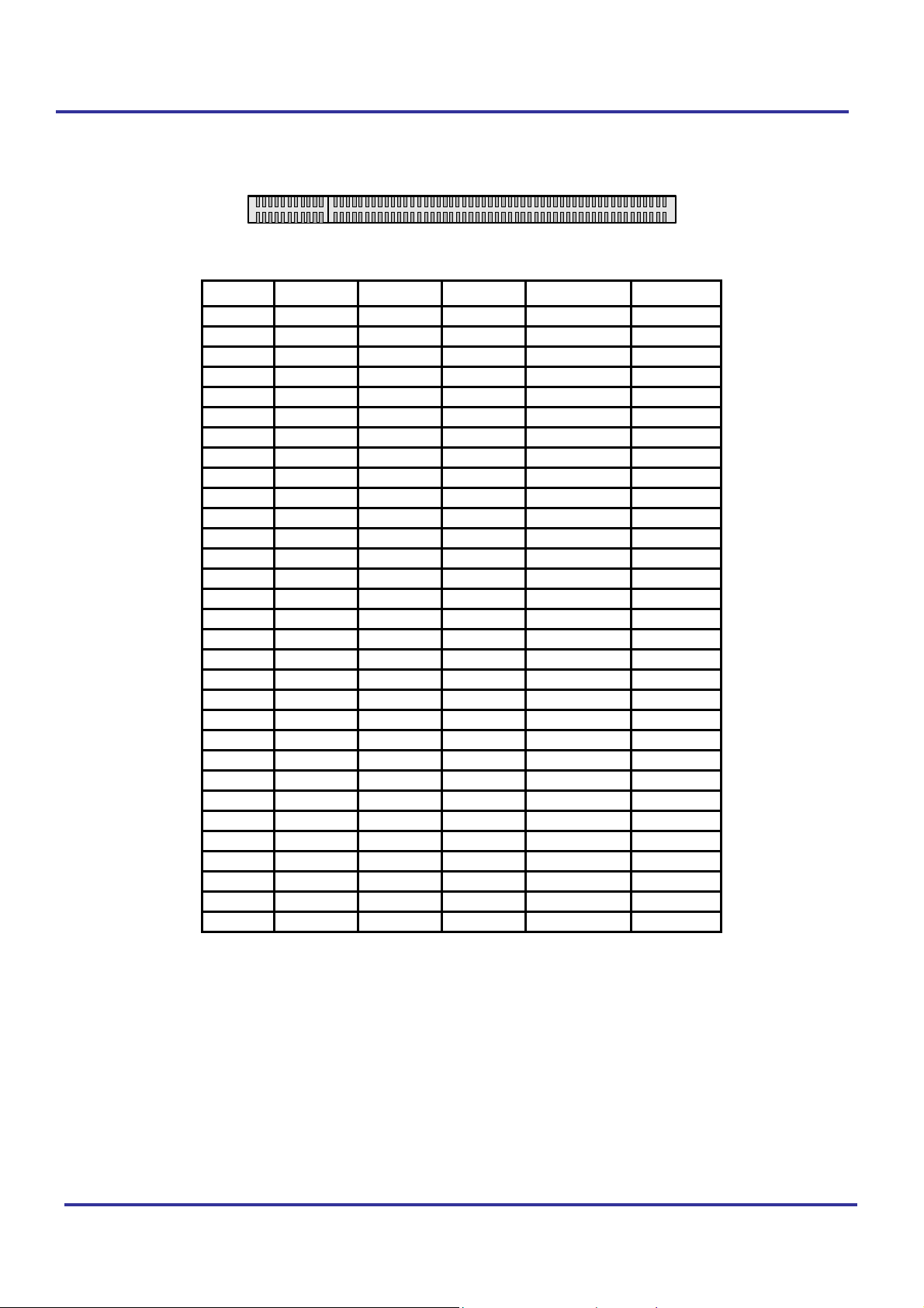
PCI bus pin assignment
Tracer 2000 DVR user manual
B1
A1
A52
B49B52
A49
SOLDER SIDE
B62
A62 COMPONENT SIDE
Pin no. A B Pin no. A B
1 TRST* -12V 32 AD16 AD17
2 +12V TCK 33 VCC3 C/BE2*
3 NC GND 34 FRAME* GND
4 NC NC 35 GND IRDY*
5 +5V +5V 36 TRDY* VCC3
6 INTA* +5V 37 GND DEVSEL*
7 INTC* INTB* 38 STOP* GND
8 +5V INTD* 39 VCC3 LOCK*
9 NC PREN1* 40 SDONE PERR*
10 +5V NC 41 SBO* VCC3
11 NC PREN2* 42 GND SERR*
12 GND GND 43 PAR VCC3
13 GND GND 44 AD15 C/BE1*
14 3VSB NC 45 VCC3 AD14
15 RST* GND 46 AD13 GND
16 +5V CLK 47 AD11 AD12
17 GNT0* GND 48 GND AD10
18 GND REQ0* 49 AD9 GND
19 PME* +5V 50 KEY KEY
20 AD30 AD31 51 KEY KEY
21 VCC3 AD29 52 C/BE0* AD8
22 AD28 GND 53 VCC3 AD7
23 AD26 AD27 54 AD6 VCC3
24 GND AD25 55 AD4 AD5
25 AD24 VCC3 56 GND AD3
26 AD16 C/BE3* 57 AD2 GND
27 VCC3 AD23 58 AD0 AD1
28 AD22 GND 59 +5V +5V
29 AD20 AD21 60 REQ64* ACK64*
30 GND AD19 61 +5V +5V
31 AD18 VCC3 62 +5V +5V
Version 3.0 Page 18 of 36
Page 19
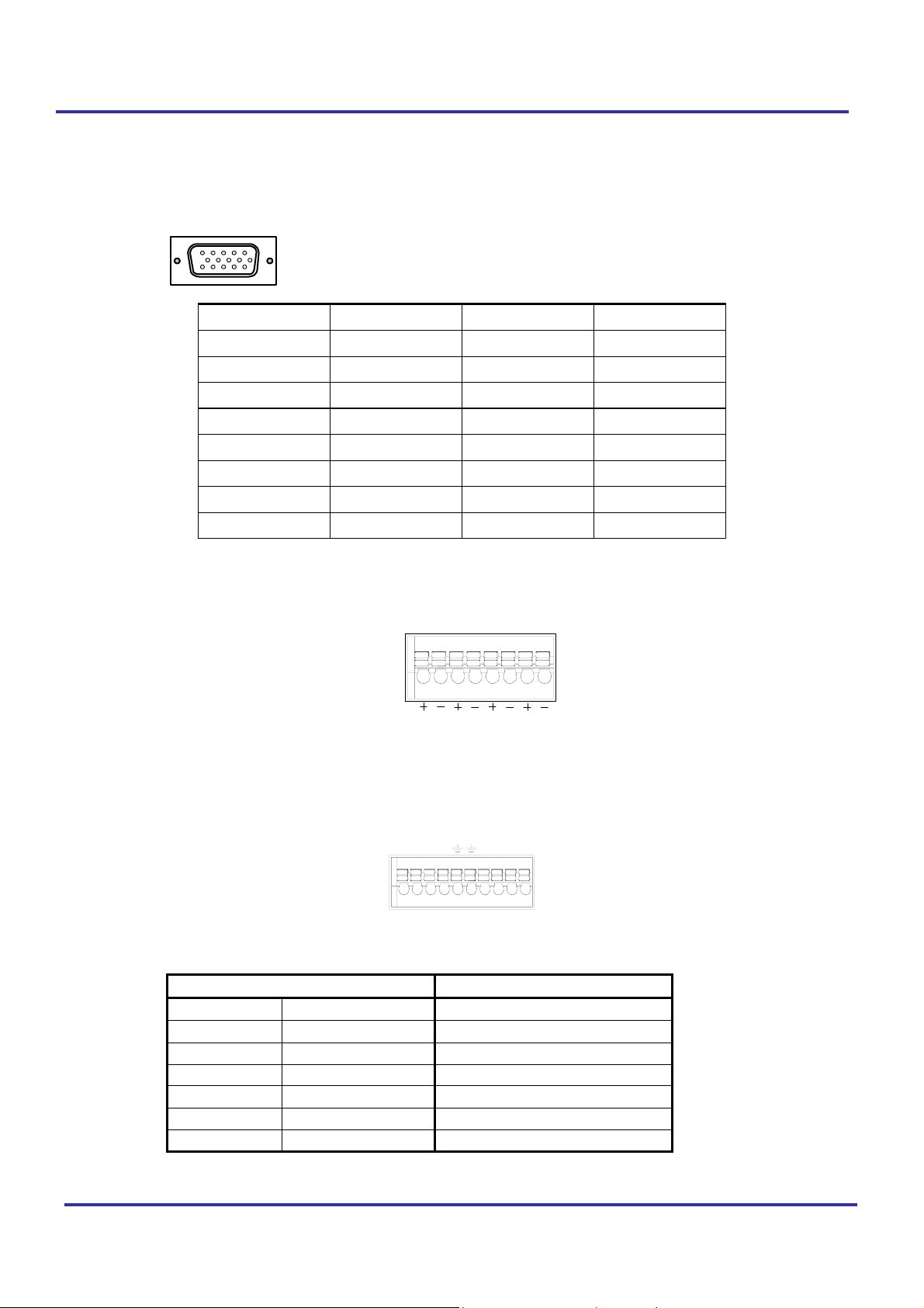
External Connector
CRT Display Connector (VGA)
Tracer 2000 DVR user manual
15
15
10
Pin no. Signal Pin no. Signal
1 RED 9 N/C
2 GREEN 10 GND
3 BLUE 11 N/C
4 N/C 12 N/C
5 GND 13 H-SYNC
6 GND 14 V-SYNC
7 GND 15 N/C
8 GND
Audio Input connector:
MIC1
MIC4MIC2 MIC3
GPIO connector:
8
57
64231
USB connector:
USB Ports Pin no. of Connector-B
Pin Name Pin
2 USB0 + 6
3 USB0 - 14
4,8 GND 16
1,5 USB power 8
6 USB1 + 7
7 USB1 - 15
Version 3.0 Page 19 of 36
Page 20
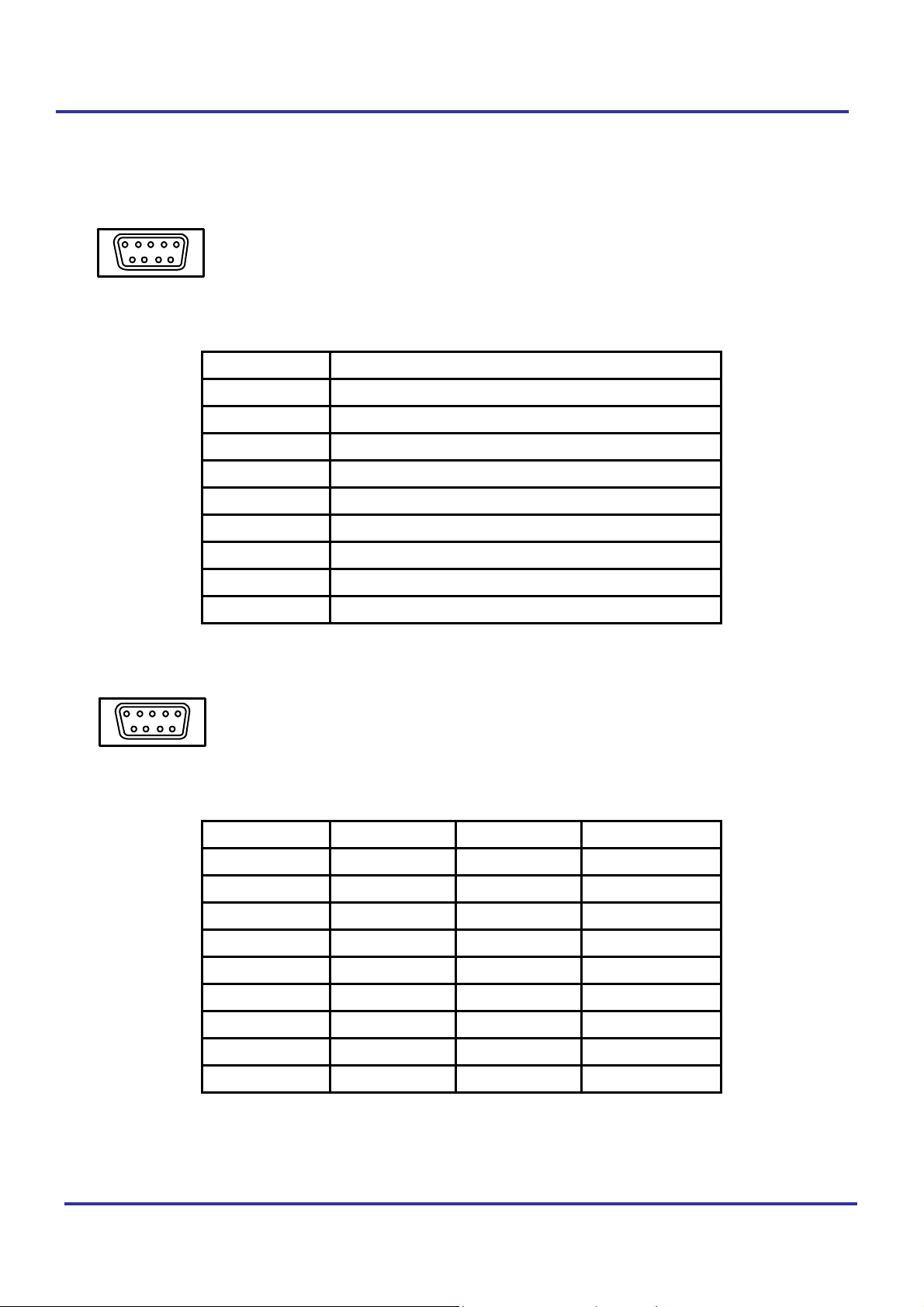
COM 1 Connector
Tracer 2000 DVR user manual
1
6
COM2 Connector
5
9
RS-232 Connector (COM1)
Pin no. Signals
1 DCD
2 RX
3 TX
4 DTR
5 GND
6 DSR
7 RTS
8 CTS
9 RI
1
6
5
9
RS-232/RS-422/RS-485 Connector (COM2) (Please setup mode type by JP3)
Pin no. RS-232 RS-422 RS-485
1 DCD TX- DATA2 RX TX+ DATA+
3 TX RX+
4 DTR RX-
5 GND GND GND
6 DSR RTS +
7 RTS RTS -
8 CTS CTS +
9 RI CTS -
Version 3.0 Page 20 of 36
Page 21
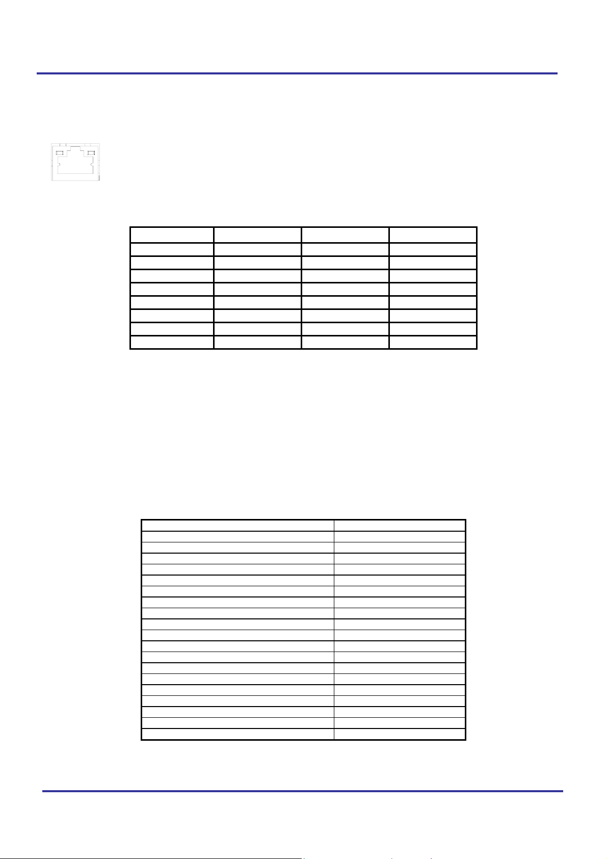
Ethernet connector (RJ-45)
Pin no. signals
1 TX+
2 TX-
3 RX+
4 NC
5 NC
6 RX-
7 NC
8 NC
Tracer 2000 DVR user manual
Drawing of Ethernet connector RJ-45
Connectors
The connectors allow this main board to connect with other parts of the system. Some
problems encountered with your system may be caused by loose or improper connections.
Ensure that all connectors are in place and firmly attached.
Component Label
HDD (IDE) connector IDE 1,IDE2
Slim FDD connector FDC
Internal USB connector USB2
Reset switch connector JP1 (6-5)
External speaker connector JP1 (14-20)
HDD LED connector JP1 (7-8)
External power connector P1
Serial Port COM1,2
Audio OUT LINE_OUT
Audio IN LINE_IN
MIC MIC_IN
CD IN CD_IN
LAN RJ-45
Video INPUT J2
CMOS RAM clear J1
Audio/GPIO J3
IR IR
CPU FAN FAN1,2
Printer PRN
Version 3.0 Page 21 of 36
Page 22
Tracer 2000 DVR user manual
P/T/Z Setting
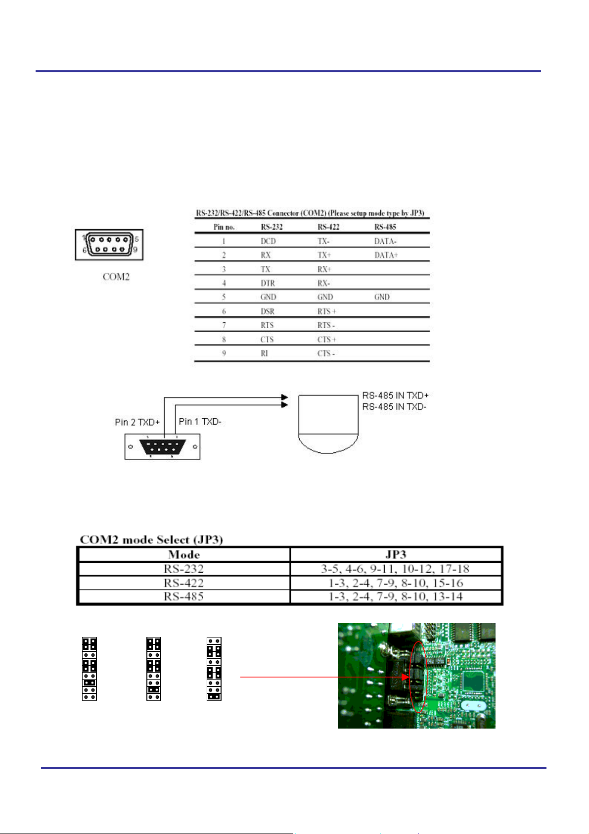
The P/T/Z Setting complies with LILIN or PELCO. Protocol has been previously attached to
the COM ports. You may control the camera via arrow buttons. In this case, you don’t need to
buy dedicated P/T/Z controller.
Pin assignment of COM2:
Connect 9 PIN Female D_SUB to COM2 (Pin defines as below)
Cable connection:Camera Input jack to COM2 for PIH-7000/7600:
For example:
Jumper setting of COM2:
The system default of COM2 is RS-485. Adjust Jumper JP3 in system for RS-422,RS-232
signals as shown below.
JP3
1
17
RS485
2
18
JP3
1
17
RS422
2
18
1
17
RS232
2
18
JP3
Version 3.0 Page 22 of 36
Page 23

Tracer 2000 DVR user manual
CHAPTER V CMOS SETTING
Introduction
This manual discusses Award™ Setup program built into the ROM BIOS. The Setup program allows
users to modify the basic system configuration. This special information is then stored in battery-backed
RAM so that it retains the Setup information when the power is turned off.
If system behaviors abnormal situation and you wish to check hardware values of CMOS…you may
connect a USB keyboard, restart the system by turning it OFF then ON or pressing the "RESET" button
on the system case. You may also restart by simultaneously pressing <Ctrl>, <Alt>, and <Delete> keys.
Press <DEL> key to enter CMOS setting pages.
Setup Pages
CMOS Setup Utility - Copyright ( C ) 1984-1998
Standard CMOS Feature
Advanced BIOS Feature
Advanced Chipset Feature
Integrated Peripherals
Power Management Setup
PnP/PCI Configurations
PC Health Status
Esc : Quit F9 : Menu in BIOS ↑ ↓ ← → : Select Item
F10 : Save & Exit Setup
Frequency/Voltage Control
Load Fail-Safe Defaults
Load Optimized Defaults
Set Supervisor Password
Set User Password
Save & Exit Setup
Exit Without Saving
Time, Date, Hard Dis k Type…
Version 3.0 Page 23 of 36
Page 24

Tracer 2000 DVR user manual
1. Standard CMOS Features
Use this menu for basic system configuration.
Date:
Time:
IDE Primary
Master
IDE Primary
Slave
IDE Secondary
Master
IDE Secondary
Slave
Drive A
Driver B
Video
Halt On
Based Memory
Extended
Memory
Total Memory
↑↓←→Move Enter: Select +/-/PU/PD: Value F10:Save ESC: Exit F1:General Help
F5:Previous Values F6:Fail-safe defaults F7:Optimized Defaults
Mon., Feb 8 1999
16:19:20
2557 MB
None
None
None
None
None
EGA/VGA
No Errors
640 K
64512 K
65536 K
Item Help
_____________________________
Menu Level
Change the day, month, year and
century
Version 3.0 Page 24 of 36
Page 25

Tracer 2000 DVR user manual
2. Advanced BIOS Features
Use this menu to set the Advanced Features available on your system.
CMOS Setup Utility – Copyright © 1984 – 1998 Award Software
Advanced BIOS Features
Virus Warning Disabled
CPU Internal Cache Enabled
External Cache Enabled
CPU L2 Cache ECC Checking Enabled
Quick Power On Self Test Disabled
First Boot device HDD-0
Second Boot device HDD-1
Third Boot device CDROM
Boot other device Enabled
Boot Up NumLock Status On
Gate A20 Option Fast
T ypematic Rate Setting Disabled
xT ypematic Rate (Ch ar s/Sec) 6
Item Help
______________________________
Menu Level
Allows you to choose the VIRUS
warning feature for IDE Hard Disk boot
sector protection. If this function is
enabled and someone attempt to write
data into this area, BIOS will show a
warning message on screen and alarm
beep
xTypematic Delay (Msec) 250
Security Option Setup
OS Select For DRAM > 64MB Non-OS2
Report NO FDD For Win 95 Yes
↑↓←→Move Enter: Select +/-/PU/PD: Value F10:Save ESC: Exit F1:General Help
F5:Previous Values F6:Fail-safe defaults F7:Optimized Defaults
Version 3.0 Page 25 of 36
Page 26

Tracer 2000 DVR user manual
3. Advanced Chipset Features
Use this menu to change the values in the chipset registers and optimize your system's
performance.
CMOS Setup Utility – Copyright © 1984 – 1998 Award Software
Advanced BIOS Features
Virus Warning Disabled
CPU Internal Cache Enabled
External Cache Enabled
CPU L2 Cache ECC Checking Enabled
Quick Power On Self Test Disabled
First Boot device HDD-0
Second Boot device HDD-1
Third Boot device CDROM
Boot other device Enabled
Boot Up NumLock Status On
Gate A20 Option Fast
T ypematic Rate Setting Disabled
xT ypematic Rate (Ch ar s/Sec) 6
Item Help
______________________________
Menu Level
Allows you to choose the VIRUS
warning feature for IDE Hard Disk boot
sector protection. If this function is
enabled and someone attempt to write
data into this area, BIOS will show a
warning message on screen and alarm
beep
xTypematic Delay (Msec) 250
Security Option Setup
OS Select For DRAM > 64MB Non-OS2
Report NO FDD For Win 95 Yes
↑↓←→Move Enter: Select +/-/PU/PD: Value F10:Save ESC: Exit F1:General Help
F5:Previous Values F6:Fail-safe defaults F7:Optimized Defaults
CMOS Setup Utility – Copyright © 1984 – 2000 Award Software
SDRAM CAS Latency T ime
SDRAM Cycle Time Tras/Trc
SDRAM RAS-to-CAS Delay
SDRAM RAS Precharge T ime
System BIOS Cacheable
Video BIOS Cacheable
Memory Hole At 15M-16M
CPU Latency Timer
Delay Transaction
AGP Graphics Aperture Size
Display Cache Frequency
System Memory Frequency
On-Chip Video Window Size
* Onboard Display Cache Setting *
CAS# Latency
Paging Mode Control
RAS-to-CAS Override
RAS# T iming
RAS# Precharge Timing
↑↓←→Move Enter: Select +/-/PU/PD: Value F10:Save ESC: Exit F1:General Help
F5:Previous Values F6:Fail-safe defaults F7:Optimized Defaults
Version 3.0 Page 26 of 36
Advanced Chipset Features
3
7/9
3
Item Help
Menu Level
3
Disabled
Disabled
Disabled
Enabled
Enabled
64MB
100MHz
Auto
64MB
3
Open
By CAS# LT
Fast
Fast
Page 27

Tracer 2000 DVR user manual
4. Integrated Peripherals
Use this menu to specify your settings for integrated peripherals
CMOS Setup Utility – Copyright © 1984 – 2000 Award Software
Integrated Peripherals
OnChip Primary PCI IDE
OnChip Secondary PCI IDE
IDE Primary Master PIO
IDE Primary Slave PIO
IDE Secondary Master PIO
IDE Secondary Slave PIO
IDE Primary Master UDMA
IDE Primary Slave UDMA
IDE Secondary Master UDMA
IDE Secondary Slave UDMA
USB Controller
USB Keyboard Support
USB Mouse Support
Init Display
AC97 Audio
IDE HDD Block Mode
POWER ON Function
xKB Power ON Password
xHot Key Power On
Onboard Serial Port 1
Onboard Serial Port 2
UART Mode Select
xRxD , TxD Active
xIR Transmi ssion Delay
xUR2 Duplex Mode
xUse IR Pins
Onboard Parallel Port
Parallel Port Mode
EPP Mode Select
ECP Mode Use DMA
PWRON After PWR-Fail
Watch Dog Timer Select
Enabled
Enabled
Auto
Auto
Auto
Auto
Auto
Auto
Auto
Auto
Enabled
Enabled
Disabled
Onboard / AGP
Auto
Enabled
BUTTON ONLY
Enter
Ctrl-F1
3F8/IRQ4
2F8/IRQ3
Normal
Hi, Lo
Enabled
Half
IR-Rx2Tx2
378/IRQ7
SPP
EPP1.7
3
Off
Disable
Item Help
_______________________________
Menu Level
If your IDE hard drive supports block
mode select Enabled for automatic
detection of the optimal number of block
read/write per sector the drive can
support
↑↓←→ Move Enter: Select +/-/PU/PD: Value F10:Save ESC: Exit F1:General Help
F5:Previous Values F6:Fail-safe defaults F7:Optimized Defaults
Version 3.0 Page 27 of 36
Page 28

Tracer 2000 DVR user manual
5. Power Management Setup
Use this menu to specify your settings for power management
CMOS Setup Utility – Copyright © 1984 – 2000 Award Software
Power Management Setup
ACPI Function
ACPI Suspend Type
Power Management
Video Off Method
Video off In Suspend
Suspend T ype
MODEM Use IRQ
Suspend Mode
HDD Power Down
Soft-Off by PWR-BTTN
Wake-Up by PCI card
Power On By Ring
USB KB Wake-Up From S3
PWRON After PWR-Fail
CPU Thermal-Throttling
Resume by Alar m
X Date(of Month) Alarm
X Time(hh:mm:ss) Alarm
** Reload Global Timer
Primary IDE 0
Primary IDE 1
Secondary IDE 0
Secondary IDE 1
FDD, COM, LPT Port
PCI PIRQ [A-D]#
Disabled
S1(POS)
User Define
DPMS
Yes
Stop Grant
3
Disabled
Disabled
Instant-Off
Disabled
Enabled
Disabled
Former-Sts
50.0%
Disabled
0
0 0 0
Events **
Disabled
Disabled
Disabled
Disabled
Disabled
Disabled
Item Help
______________________________
Menu Level
↑↓←→Move Enter: Select +/-/PU/PD: Value F10:Save ESC: Exit F1:General Help
F5:Previous Values F6:Fail-safe defaults F7:Optimized Defaults
Version 3.0 Page 28 of 36
Page 29

Tracer 2000 DVR user manual
6. PnP / PCI Configuration
This entry appears if your system supports PnP / PCI.
CMOS Setup Utility – Copyright © 1984-2000 Award Software
PnP/PCI Configurations
Reset Configuration Data
Resources Controlled By
X IRQ Resources
PCI/VGA Palette Snoop
Disabled
Auto(ESCD)
Press Enter
Disabled
Item Help
-----------------------------------------Menu Level
Default is Disabled. Select Enabled
to reset Extended System
Configuration Data(ESCD) when you
exit Setup if you have installed a new
add-on and the system
reconfiguration has caused such a
serious conflict that the OS cannot
boot
↑↓←→Move Enter: Select +/-/PU/PD: Value F10:Save ESC: Exit F1:General Help
F5:Previous Values F6:Fail-safe defaults F7:Optimized Defaults
Version 3.0 Page 29 of 36
Page 30

Tracer 2000 DVR user manual
7. PC Health Status
Use this menu to monitor the CPU and system temperature, CPU fan speed the v olt ag e of the
onboard regulators.
CMOS Setup Utility – Copyright © 1984-2000 Award Software
PC Health Status
CPU Warning Temperature
Current System Temp.
Current CPU1 Temperature
IN0(V)
IN1(V)
IN2(V)
+ 5 V
VBAT(V)
5VSB(V)
Disabled
Disabled
Item Help
Menu Level
Shutdown temperature
↑↓←→ Move Enter: Select +/-/PU/PD: Value F10:Save ESC: Exit F1:General Help
F5:Previous Values F6:Fail-safe defaults F7:Optimized Defaults
8. Frequency/Voltage Control
Use this menu to specify your settings for frequency/voltage co ntrol.
CMOS Setup Utility – Copyright © 1984-2000 Award Software
Frequency/ Voltage Control
Auto Detect DIMM/PCI CLK
Spread Spectrum
Enabled
Disabled
Item Help
------------------------------------------------Menu Level
↑↓←→ Move Enter: Select +/-/PU/PD: Value F10:Save ESC: Exit F1:General Help
F5:Previous Values F6:Fail-safe defaults F7:Optimized Defaults
Version 3.0 Page 30 of 36
Page 31

Tracer 2000 DVR user manual
9. Load Optimized Defaults
Use this menu to load the BIOS default values that are factory settings for optimal
performance system operations. While Award has designed the custom BIOS to maximize
performance, the factory has the right to change these defaults to meet their needs. .
Load Optimized Defaults (Y/N)? N
Pressing ‘Y’ loads th e default value s that are factory settin gs for optimal p erformance s ystem
operations.
10. Supervisor / User Password
Use this menu to set User and Supervisor Passwords.
11. Save & Exit Setup
Save CMOS value changes to CMOS and exit setup.
12. Exit Without Save
Abandon all CMOS value changes and exit setup. .
Version 3.0 Page 31 of 36
Page 32
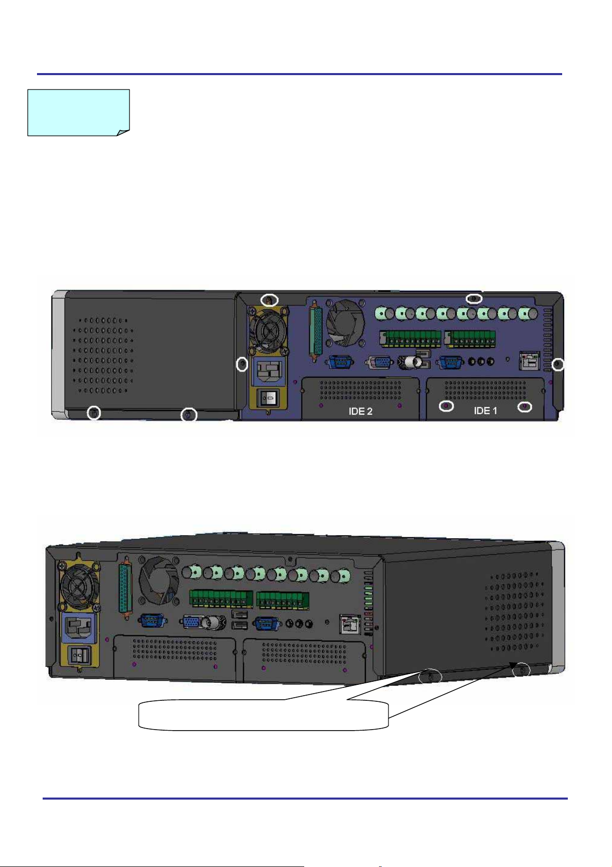
CHAPTER VI System HDD Installation Guide
Follow the step to setup HDD drawing box.
1. Remove the screws on the case. (marked in while circles)
Tracer 2000 DVR user manual
Version 3.0 Page 32 of 36
Remove the screws on the case.
Page 33
Tracer 2000 DVR user manual
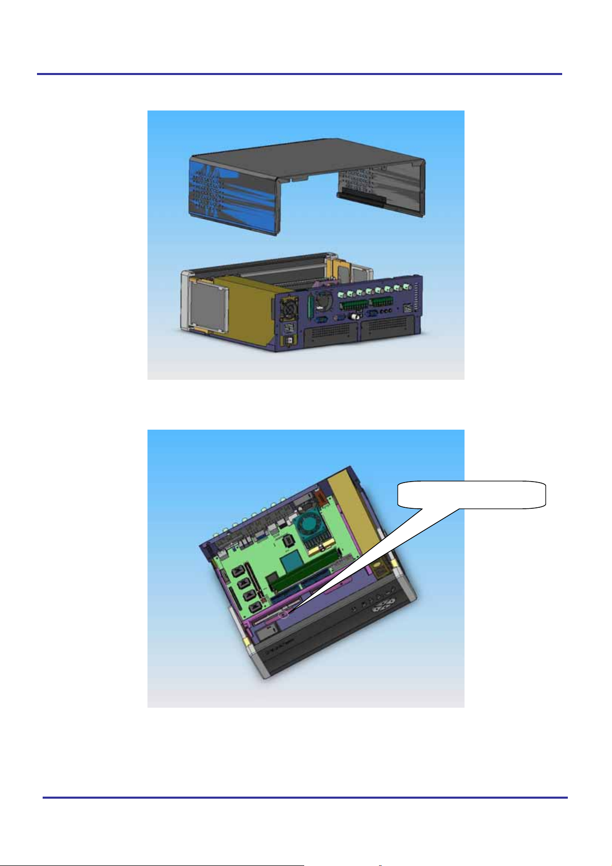
2. Take off the upper cover and remove the screws.
Remove the screw.
Version 3.0 Page 33 of 36
Page 34
Tracer 2000 DVR user manual
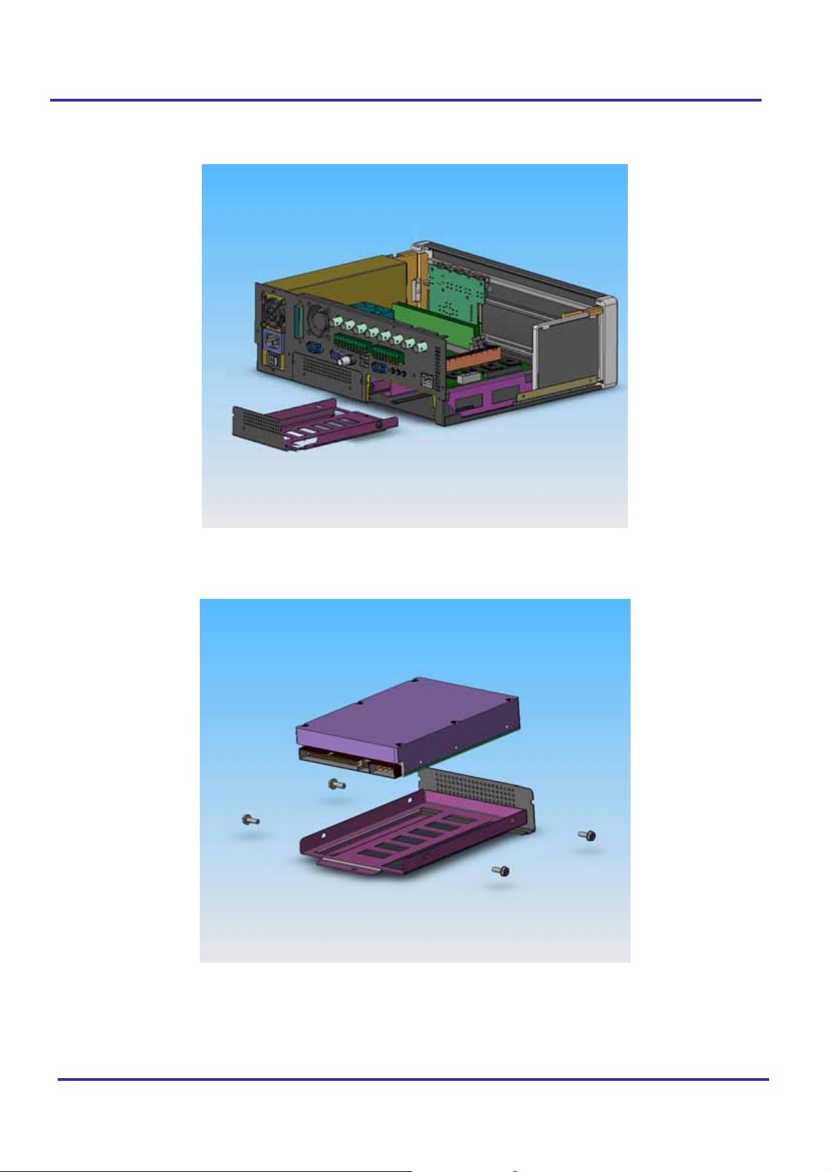
3. Remove HDD Tray, and install HDD properly.
Version 3.0 Page 34 of 36
Page 35
Tracer 2000 DVR user manual
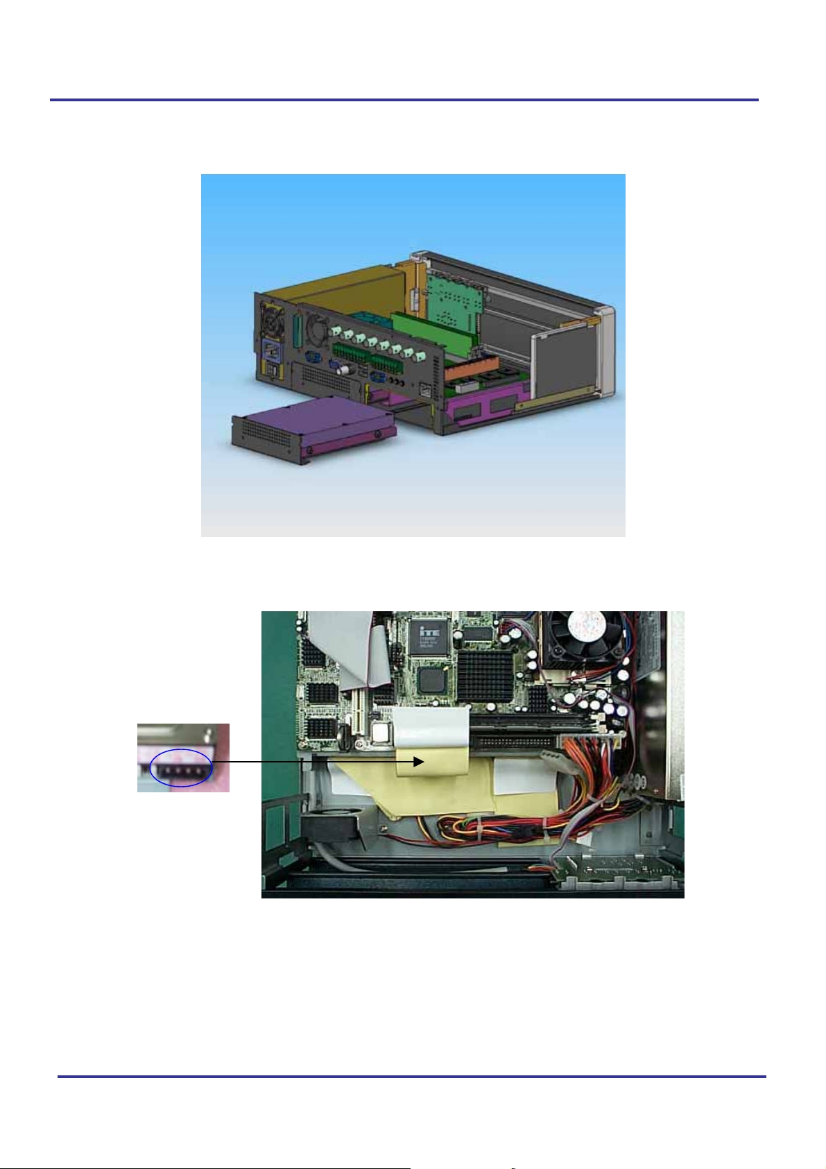
4. Insert the assembled HDD tray into TRACER2000, and connect both Power and HDD
cables.
Version 3.0 Page 35 of 36
Page 36
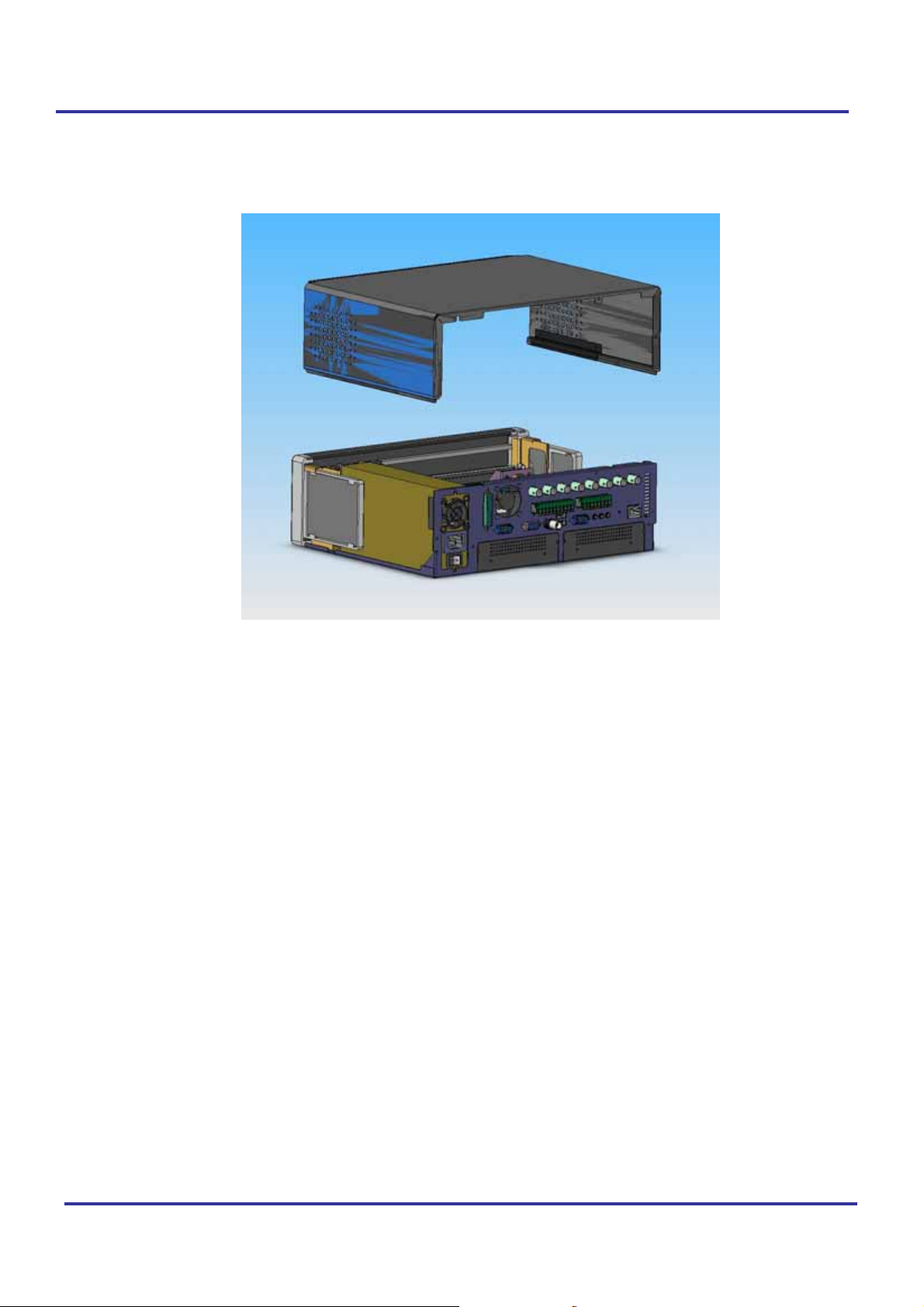
Tracer 2000 DVR user manual
5. Assemble the upper cover and the screws.
Version 3.0 Page 36 of 36
 Loading...