

Page 1

ART P001306017 - REV R20160906
P001306017
GIANT D263S / D263SW / D332ST / D332SWT EN-US
D263S / D263SW / D332ST /
D332SWT
WHEEL LOADER
OPERATOR MANUAL
EN-US - Original language
Page 2

2
Page 3

3
1 General information ................ 5
Preface - - - - - - - - - - - - - - - - -6
Manual usage - - - - - - - - - - - - - -7
Proper Machine Use - - - - - - - - - - -8
Service/Dealership Network - - - - - - -9
Vibration Information- - - - - - - - - - -9
2 Applications........................... 13
Wheel Loader application - - - - - - - 14
Exclusions- - - - - - - - - - - - - - - 14
Public road - - - - - - - - - - - - - - 15
Working surface - - - - - - - - - - - - 15
Attachments - - - - - - - - - - - - - - 16
Operating the machine- - - - - - - - - 17
3 Operation ............................... 21
Machine components - - - - - - - - - 22
Functions - - - - - - - - - - - - - - - 22
ROPS + FOPS protection - - - - - - - 24
Entering and Exiting - - - - - - - - - - 25
4 Safety ..................................... 27
SAFETY- - - - - - - - - - - - - - - - 28
Safety Signs- - - - - - - - - - - - - - 41
ANSI-Style and Common Safety Decal Locations. - - - - - - - - - - - - - - - - 43
Slopes- - - - - - - - - - - - - - - - - 52
Safety - Hydraulic parts - - - - - - - - 52
Safety precautions - - - - - - - - - - - 55
5 Technical data ....................... 67
Diesel engine - - - - - - - - - - - - - 68
General - - - - - - - - - - - - - - - - 69
Tipping loads - - - - - - - - - - - - - 70
Dimensions - - - - - - - - - - - - - - 71
Trailer - - - - - - - - - - - - - - - - - 73
Tyres - - - - - - - - - - - - - - - - - 73
6 Commissioning ..................... 75
First inspection - - - - - - - - - - - - 76
Ignition switch - - - - - - - - - - - - - 76
Driving - - - - - - - - - - - - - - - - 77
Parking - - - - - - - - - - - - - - - - 78
Joystick - - - - - - - - - - - - - - - - 79
Attachment locking - - - - - - - - - - 79
ATTACHMENT POSITION - - - - - - - 80
Third function - - - - - - - - - - - - - 81
Fourth function (electrical) - - - - - - - 81
Dashboard- - - - - - - - - - - - - - - 82
Alternator warning light- - - - - - - - - 82
Engine temperature - - - - - - - - - - 83
Engine temperature warning light - - - - 83
Engine oil pressure warning light - - - - 83
Combination switch - - - - - - - - - - 83
Switches in cabin - - - - - - - - - - - 84
Engine cover- - - - - - - - - - - - - - 84
Fuses - - - - - - - - - - - - - - - - - 85
Engine oil - - - - - - - - - - - - - - - 87
Tire pressure - - - - - - - - - - - - - 88
Wheel maintenance - - - - - - - - - - 88
Hydraulic oil level - - - - - - - - - - - 89
Grease points - - - - - - - - - - - - - 90
Refuel - - - - - - - - - - - - - - - - - 91
Driver's seat - - - - - - - - - - - - - - 91
Steering column - - - - - - - - - - - - 92
Pro-inching - - - - - - - - - - - - - - 93
Articulation lock bar - - - - - - - - - - 94
Tie down- - - - - - - - - - - - - - - - 95
Lifting - - - - - - - - - - - - - - - - - 96
Towing - - - - - - - - - - - - - - - - 97
Loading - unloading - - - - - - - - - - 98
7 Maintenance ...........................99
Performing maintenance - - - - - - - 100
Liquids- - - - - - - - - - - - - - - - 100
Brake fluid - - - - - - - - - - - - - - 101
Coolant Level - - - - - - - - - - - - 101
Coolant - - - - - - - - - - - - - - - 102
Engine oil - - - - - - - - - - - - - - 102
Engine oil and filter- - - - - - - - - - 103
Fuel - - - - - - - - - - - - - - - - - 104
Hydraulic oil - - - - - - - - - - - - - 104
Wheel nuts - - - - - - - - - - - - - 105
Maintenance Schedule - - - - - - - - 106
Maintenance log - - - - - - - - - - - 109
8 Malfunctions.........................117
Possible malfunctions - - - - - - - - 118
9 Environment.........................119
Care for the Environment- - - - - - - 120
Page 4

4
10 Serial numbers .................. 121
Serial number registration - - - - - - 122
11 index................................... 125
EC Declaration of Conformity - - - - 129
Page 5

5
1. GENERAL
INFORMATION
Page 6

6
1.General information
PREFACE
You have chosen for a GIANT Wheel Loader, ensuring versatile use and durability.
Thank you for your confidence in our products.
You will get the best benefit of this Wheel Loader by carefully following the safety,
maintenance and operation instructions in this manual.
We strongly recommend each operator to read this manual carefully before use.
Ensure that the Wheel Loader is always accompanied by this manual. For the
latest version of this manual, go to www.tobroco-giant.us.
Tobroco Machinery LLC is not responsible for damage and indirect damage
caused by operator error, lack of (skilled) maintenance and any other use other
than described in this manual. Tobroco Machinery LLC cannot be held liable for
any damages resulting from unauthorized modifications and/or additions to the
Wheel Loader, without our prior written consent.
Tobroco Machinery LLC continually strives to improve her products and services.
We therefore reserve the right to change the specifications in this user manual at
any time without prior notice. It is possible that the pictured drawings and photos
do not exactly match your Wheel Loader.
We are confident that you will be very satisfied with your new GIANT Wheel
Loader.
While the content of this manual has been prepared with the utmost care, some
information may nevertheless be incomplete, incorrect or may become outdated in
time. TO THE FULLEST EXTENT PERMISSIBLE BY LAW, Tobroco Machinery
LLC MAKES NO REPRESENTATIONS OR WARRANTIES OF ANY KIND,
WETHER EXPRESS OR IMPLIED, FOR THE CURRENCY, ACCURACY, OR
COMPLETENESS OF ANY INFORMATION, AS DEFINED ABOVE.
FURTHERMORE, Tobroco Machinery LLC MAKES NO REPRESENTATIONS OR
WARRANTIES IN CONNECTION TO ITS PRODUCTS AND/OR SERVICES,
INCLUDING WARRANTIES ABOUT ITS SERVICES’ AND PRODUCTS’
MERCHANTABILITY OR FITNESS FOR A PARTICULAR PURPOSE, UNLESS
EXPLICITLY MADE AND PROVIDED BY Tobroco Machinery LLC IN WRITING
TO THE PURCHASER OF THE SERVICES AND/OR PRODUCTS.
© All rights reserved by Tobroco Machinery LLC 2016
Page 7

7
1.General information
MANUAL USAGE
Contents and Use of this Manual
This operator manual provides detailed operating procedures for safe, effective
and proper machine use. Safe operation is detailed in the Safety chapter of this
manual. Specification, maintenance and troubleshooting information is also
included in this manual.
Improper operation, inspection and maintenance of the machine can result in
injury or death. Read and understand the contents of this manual completely and
become familiar with the machine before operation. Contact your authorized
dealer with any questions about information in this manual, if extra manuals are
required, or about availability of manuals in other languages.
Throughout this manual, information is provided set in or italic type and introduced
by the words Notice or Important. Carefully read and follow these messages to
improve operating and maintenance efficiency, to avoid breakdowns and damage,
and extend the life of the machine.
Note: Because of ongoing product improvements, illustrations and listings in this
manual may not exactly match the machine. Tobroco Machinery LLC reserves the
right to modify and improve products at any time without notice.
A storage facility is provided for manual storage. Store the operator manual in this
facility at all times.
This manual is considered a permanent part of the machine and should be with the
machine at all times. Replace this manual promptly if it becomes damaged, lost, or
stolen.
Ownership Change
If the machine is resold, include this operator manual as part of the sale.
If the machine was purchased “used,” or if the owner's address has changed,
please provide your dealer or Tobroco Machinery LLC with the owner's name and
current address, along with the machine model and serial numbers. This will allow
the registered owner information to be updated, so that the owner can be notified
directly in case of an important product issue, such as a safety update program.
Page 8

8
1.General information
Manufacturer Information
Products described in this manual manufactured by Tobroco Machinery LLC.
Machine Designation
Earth-Moving Machinery / Loaders / Compact / Seated Operator
PROPER MACHINE USE
Improper use of the machine can result in property damage, injury or death.
The machine is designed only for digging, picking up, lifting, transporting and
unloading materials. Use with approved attachments is also allowed. Use in any
other way is considered as contrary to the intended use. Compliance with, and
strict adherence to, the conditions of operation, service and repair, as specified by
the manufacturer, also constitute essential elements of the intended use.
The machine was designed and built according to the best available technology
and approved safety regulations in the countries where it is sold. However, it is
impossible to completely safeguard against abusive and/or improper use. The
operator must always consider potential safety risks and hazards during operation.
Accident prevention regulations, all other generally recognized regulations on
safety and occupational medicine, and all road traffic regulations, must be
observed at all times.
The machine must be maintained in proper operating condition. Any damaged or
malfunctioning parts must be repaired or replaced immediately.
Any arbitrary modifications carried out to the machine may relieve the
manufacturer of liability for any resulting damage or injury.
Using Attachments
Read all documentation provided with attachments to learn how to safely operate
and maintain them.
WARNING
Page 9

9
1.General information
Do not use the machine for any applications or purposes other than those
described in this manual or manuals supplied with attachments. Contact the
Tobroco Machinery LLC Service Department before using attachments or
equipment not approved by Tobroco Machinery LLC, or if there are any questions
about approved attachments. Use of non-approved attachments or unauthorized
modifications is prohibited.
SERVICE/DEALERSHIP NETWORK
Your dealership network stands ready to provide any assistance that may be
required, including providing genuine service parts. All service parts should be
obtained from your dealer. Provide complete information about the part and
include the machine model and serial numbers. Record these numbers in the
spaces provided in chapter "Serial Numbers".
Tobroco Machinery LLC strives to continuously improve its products and reserves
the right to make changes and improvements in the design and construction of any
part without incurring the obligation to install such changes on any previously
delivered machine.
VIBRATION INFORMATION
Compact construction equipment is generally used in harsh environments. This
type of usage can expose an operator to uncomfortable levels of vibration. It is
useful to understand exposure to vibration levels when operating compact
equipment and what can be done to reduce vibration exposure. As a result,
equipment operation can be more efficient, productive and safe.
An operator's exposure to vibration occurs in two ways:
• Whole-Body Vibration (WBV)
• Hand-Arm Vibration (HAV)
WBV issues are primarily addressed in this manual, because evaluations have
shown that operation of mobile compact construction equipment on work sites
typically results in HAV levels less than the allowed exposure limit of 2.5 m/s2.
Page 10

10
1.General information
Member States of the European Union must comply with the Physical Agents
(vibration) Directive, 2002/44/EC.
Effective control of vibration exposure for an operator involves more than just
vibration levels on the machine. The work site, how the machine is used, and
proper training all play important roles in reducing vibration exposure.
Vibration exposure results from:
• Work site conditions.
• How the machine is operated.
• The machine characteristics.
Common causes of high WBV levels:
• Using a machine that is improper for the task.
• Work site with potholes, ruts and debris.
• Improper operating techniques, such as driving too fast.
• Incorrect adjustment of the seat and controls.
• Other physical activities while using the machine.
Vibration Measurement and Actions
The vibration directive places the responsibility for compliance on employers.
Actions that should be followed by employers include:
• Assess the levels of vibration exposure.
• Determine from this assessment if operators will be exposed to vibration levels
above the limits stated in the directive.
• Take appropriate actions to reduce operator's exposure to vibration.
• Provide operators with information and training to reduce their exposure to
vibration.
• Keep good records and update operations and training on a regular basis.
If the assessment concludes that vibration level exposure is too high, one or more
of the following actions may be necessary:
1. Train operators
• Perform operations (accelerating, steering, braking, etc.) in a smooth manner.
• Adjust the controls, mirrors and seat suspension for comfortable operation.
• Travel across the smoothest parts of the work site and avoid ruts and potholes.
2. Choose proper equipment for the job
• Use machines with the proper power and capacity.
• Select machines with good suspension seats.
• Look for controls that are easy to use.
• Ensure good visibility from the operator's position.
Page 11

11
1.General information
3. Maintain the work site
• Smooth ruts and fill potholes in traffic areas whenever possible.
• Clean up debris frequently.
• Vary traffic patterns to avoid exposure to rough terrain.
4. Maintain the equipment
• Ensure correct tire pressures.
• Check that seat suspension and all controls work smoothly and properly.
Vibration Level
The typical whole-body vibration level for the machine is listed in the declaration of
conformity, see chapter “EC Declaration of conformity”.
Page 12

12
1.General information
Page 13

13
2. APPLICATIONS
Page 14

14
2.Applications
WHEEL LOADER APPLICATION
The Wheel Loader is designed for lifting and moving:
• Substances such as sand or gravel with closed or open bucket
• Materials and parts on pallets with pallet forks
• Manure with a manure fork
• Kerbs with kerb clamp
• Stones with stone clamp
• Trees with tree harvester
• Hay bales with bale fork
CAUTION:
Use the Wheel Loader only for the above work.
EXCLUSIONS
The Wheel Loader is not designed for the lifting and moving of:
• Persons and animals
• Products where toxic and / or explosive substances may be released during
handling
• Products containing hazardous substances
• Tanks with liquid
• Combustibles
• Other liquids and dangerous substances not mentioned above
Page 15

15
2.Applications
PUBLIC ROAD
CAUTION:
Be aware of the local traffic regulations. Make sure that your machine
complies with the laws and regulations in your area.
CAUTION:
Use of public roads with the Wheel Loader is NOT allowed, unless the
Wheel Loader is equipped with a GIANT road kit which includes automotive lighting.
Please note:
• Driving on public roads should be avoided wherever possible. The different
dimensions and performance can result in unexpected situations for other
road users.
• Driving on the highway is absolutely not allowed.
• Obey national and local traffic and road regulations on public roads. This might
imply additional features on the Wheel Loader.
• Verify whether you need an insurance for driving on public roads, in addition to
the standard insurance.
• The maximum allowable speed on public road depends on local law and regu-
lations.
• Shield the attachments.
• Read the instructions that come with the attachment.
• Put the attachment in a position which does not block the vision of the driver
and which will not endanger other road users.
• Use dimmed lights during the day where visibility is seriously restricted, and at
night.
WORKING SURFACE
CAUTION:
Driving on slopes should be avoided at all times! the risk of tipping
over increases extremely when driving on slopes.
• The Wheel Loader is designed for riding on flat, hard surfaces. Only drive on
slopes when the loader attachment is empty. In the event that the wheel loader
should drive on a slope, the maximum slope angle is 11.3º (20%).
• The stability of the Wheel Loader depends on the articulation angle, load and
the lifting height. For the maximum load see chapter “Technical Data”.
• The Wheel Loader is not designed to tow other vehicles except trailers with
specifications according to chapter “Technical Data”.
Page 16

16
2.Applications
ATTACHMENTS
Only original GIANT attachments and options are allowed on the Wheel Loader.
• Earth bucket
• High-tip bucket
• Pallet fork
• Manure fork
• Feed- and manure scraper
• Auger bucket
• Kerb stone clamp
• Brick clamp
• Silage cutter
• Mixing bucket
• Straw blower
• Bucket brush
•Hay Bale Fork
• Bale grabber
Make sure that the quick-coupling system on the
attachment is the same as that on the Wheel
Loader.
Do not overload the attachment. Refer to the
Technical data section of the attachment and of
the Wheel Loader. The lowest load limit of the
two is the one you must obey.
If you want to use a non-GIANT attachment,
make sure that you have a written consent from
Tobroco Machinery LLC that you can use this
attachment safely.
Tobroco Machinery LLC is excluded from any liability for damage and
consequential damage due to non-GIANT products
Page 17

17
2.Applications
OPERATING THE MACHINE
CAUTION:
Driving on slopes should be avoided. The risk of tipping over
increases extremely when driving on slopes.
CAUTION:
Only drive on slopes when the loader attachment is empty. In the
event that the wheel loader should drive on a slope, the maximum
slope angle is 11.3º (20%).
1. Get on and off safely when entering or leaving the operator’s cab. Face the
machine. Always maintain a three point contact with the steps and handrails.
Do not use control levers as handles. Do not jump on or off the machine.
Never try to get on or off a moving machine.
2. Do not start engine or operate levers from anywhere other than the seat.
3. Before starting the engine, fasten the seat belt, make sure that the direction
lever is set in the neutral position, the parking brake switch is actuated and the
bucket is lowered to the ground.
4. Do not start engine by shorting across starter terminals.
5. Watch where you are going at all times. Watch for and avoid obstacles.
6. Never permit passengers on the machine. Keep bystanders away from the
machine during operation.
7. When working around other machines, let the other operators know what you
are doing at all times.
8. Never allow anyone to get under or near the bucket or attachment when it is
raised.
9. When raising the bucket or attachment, take extra caution to prevent it from
touching overhead wires or other obstacles. Contact with wires may cause
fatal injuries.
10. Keep away from the muffler while the engine is running and immediately after
it has stopped.
11. Hazardous operation such as on dangerous terrain, beyond the load capacity
or contrary to the intended use of the machine must be avoided as it may
cause the machine to tip over.
12. Do not drive the machine close to edges of ditches or banks which may
collapse under the weight of the machine, especially when the ground is loose
or wet.
13. Slow down for turns, uneven terrain and slopes to avoid tipping over.
14. When transporting a load, keep the loader bucket as low as possible to avoid
tipping over. Be extremely careful when working on inclines.
15. Operation on slopes can be dangerous. Rain, snow, gravel soft ground, etc.
will change the surface conditions. Do not operate the machine in questiona-
Page 18

18
2.Applications
ble surface conditions. If operating on a slope or ramp, always slow down,
travel straight up and down the incline and not across. Keep the bucket as low
as possible. If you do not follow these instructions, the machine can go out of
control and tip over.
16. Avoid turning on a slope.
17. Never perform digging or shoveling with the machine in the articulated condi-
tion, or the machine may tip over.
18. Never dig or shovel at high speed. Such operation can cause the machine to
lose stability and its rear wheels to lift off the ground, which may lead to serious personal injury or fatal accidents.
19. Do not go up or down a 20° or steeper hill. Otherwise, the machine may skid
sideways or turn on its side. If the ground is not level or is soft, limit the slope
below 11.3º (20%).
20. To avoid tipping over, do not operate the machine on any site where the terrain
cannot be ascertained, such as ground covered with seeds or snow and check
for hidden projections, dips, road shoulders, etc. beforehand, and take care
not to approach them during work.
21. Be sure to ease off the accelerator pedal at the end of filling in trenches or
areas at the edge of a steep slope or pond bank or at the brow of a hill. When
the external load is reduced, the machine speed will automatically increase,
therefore reduce speed to avoid entering ditches or tipping over.
22. To avoid the machine slipping or tipping over, do not operate the machine on
ungraded or soft terrain, such as land fills. Grade and compact the site
beforehand at all times.
23. Do not run the engine indoors. Carbon monoxide gas from exhaust is
colorless, odorless and deadly.
24. Check that no one is near the machine before starting the engine to avoid dan-
ger from the machine. Check that there are no flammable objects, such as
dead leaves, sheets of paper, or pieces of cloth near to the engine before starting the engine.
25. Be especially careful when reversing and watch the area behind the loader
exactly before starting to drive.
Caution with children
26. Serious accidents can occur if the operator does not pay attention to children
in the vicinity of the machine. Children are unpredictable!
27. Always keep an eye on children as they change their location continuously.
28. Make sure no children are within the working range of the machine.
29. Be extremely cautious when children approach the working area; stop
working, if necessary.
30. Do not carry children on the machine.
31. Do not allow children to operate the machine.
32. Do not allow children to play around the machine.
Page 19

19
2.Applications
Page 20

20
2.Applications
Page 21

21
3. OPERATION
Page 22

22
3.Operation
MACHINE COMPONENTS
FUNCTIONS
This Wheel Loader is designed for lifting and moving loads. Do not exceed the
maximum loads as shown in chapter ‘Technical data’. Various functions are
powered by a diesel engine. All of these functions can be controlled by the driver
by means of a joystick, steering wheel, pedals, and various buttons. These
functions are:
• Forward and reverse drive.
• Articulated steering.
• Lifting and lowering.
• Tilting of the tool carrier.
1. Tilt cylinder
2. Lifting arm
3. Dashboard
4. Steering wheel
5. Joystick control
6. Seatbelt buckle
7. Driver’s seat
8. Safety roof
9. Engine cover
10. Coupling pins
11. Attachment bracket
12. Wheel
13. Fuel tank filler cap
14. Articulation point
15. Steering cylinder
16. Battery
17. Hydraulic oil tank
18. Cooler
19. Engine exhaust
20. Diesel engine
21. Air filter
22. Drive pump
23. Work pump
123456789
1716
15
1413121110
18
19
20 23
22
21
Page 23

23
3.Operation
• Locking the attachments.
• Controlling / powering of attachments.
The Wheel Loader is equipped with a dashboard, which contains various controls
and indicators.
The Wheel Loader is equipped with a lifting arm. The forces that can be provided
by the arm strongly depend on the position of the lifting arm and the position of the
load.
Ensure at all times that the load is in the lowest possible position when driving and/
or steering. As the driver you are responsible for the safe operation of the
machine.
Page 24

24
3.Operation
ROPS + FOPS PROTECTION
The Wheel Loader has a ROPS. The safety
structure is tested according to the "EN ISO
3471" standard (ROPS: Roll-over protective
structures).
The Wheel Loader has a FOPS. The safety
structure is tested according to the "EN ISO
3449" standard (FOPS: Falling-object
protective structures).
All models are tested according to EN ISO
3449 (FOPS) and according to the EN ISO
3471 (ROPS).
A. Safety roof
B. Cabin
FOPS = Falling Objects Protective Structure:
Protects the driver against falling objects.
ROPS = Roll Over Protective Structure:
Protects the user if the Wheel Loader
unexpectedly tips over.
FOPS: EN ISO 3449
ROPS: EN ISO 3471
A
B
Page 25

25
3.Operation
ENTERING AND EXITING
CAUTION:
Maintain three-point contact and face the machine
at all times when entering
and exiting. Do not use
the steering wheel for
entry or exit. Never enter
or exit a moving machine.
Failure to maintain threepoint contact may result
in injury.
A
B
C
A
B
C
Page 26

26
3.Operation
Page 27

27
4. SAFETY
Page 28

28
4.Safety
SAFETY
This manual and decals on the machine warn of safety hazards and should be
read and observed closely.
Before operating the machine, first read and study the safety information in this
manual. Additionally, anyone who operates or works on the machine must be
familiar with these safety precautions.
This safety alert symbol means ATTENTION! ALWAYS BE ALERT!
YOUR SAFETY IS INVOLVED! This symbol is used throughout this
operator manual and on the decals on the machine.
“DANGER” indicates an imminently hazardous situation,
which, if not avoided, will result in death or serious injury.
“WARNING” indicates a potentially hazardous situation,
which, if not avoided, could result in death or serious
injury.
“CAUTION” indicates a potentially hazardous situation,
which, if not avoided, may result in minor injury or
property damage. It is also used to alert users of unsafe
practices.
It is essential that operators are thoroughly trained in the safe operation of the
machine and handling loads. Operators must not be physically or mentally
impaired. Do not allow minors or unqualified personnel to operate the machine, or
to be near the machine unless they are properly supervised. It is recommended
that the operator be capable of obtaining a valid motor vehicle operator's license.
Use of this machine is subject to certain hazards that cannot be eliminated by
mechanical means, but only by exercising intelligence, care and common sense.
Such hazards include: hillside operation, overloading, load instability, poor
maintenance, and using the machine for a purpose for which it was not intended or
designed.
Tobroco Machinery LLC always takes operator's safety into consideration during
the design process. Guards and shields are provided, which protect the operator
and bystanders from moving parts and other hazards. Operators must be alert,
DANGER
WARNING
CAUTION
Page 29

29
4.Safety
however, because some areas cannot be guarded or shielded without preventing
or interfering with proper operation.
Different applications may require optional safety equipment. Be sure you know
the work site hazards and equip the machine and the operator as necessary. The
information in this manual does not replace any applicable safety rules and laws.
Before operating the machine, know the rules and laws for your area. Make sure
the machine is equipped as required according to these rules/laws.
Remember that some risks of injuries may not be immediately apparent.
Exhaust gases and noise pollution may not be visible, but these hazards can
cause permanent injuries.
Some photographs in this manual may show doors, guards and shields open or
removed for the purposes of illustration only. Be sure that all doors, guards and
shields are in the proper operating positions before starting the engine to operate
the machine.
ROPS/FOPS
The machine is for the safety of the operator always
equipped with a four-post ROPS/FOPS, which may
never be removed or modified. See chapter operation,
section ROPS + FOPS.
WARNING
Page 30

30
4.Safety
Mandatory Safety Shutdown Procedure
BEFORE cleaning, adjusting, lubricating, fueling, or servicing the machine, or
leaving it unattended:
1. Bring the machine to a complete stop on a level surface. Avoid parking on an
incline or hillside, but if this is not possible, park along the slope, not across.
Prevent the machine from moving, block the tires with wedges for example.
2. Be sure all working equipment and/or attachments are stopped and the
auxiliary valve is in neutral.
3. Lower the lift arm and attachment completely.
4. Place forward/reverse drive switch (on top of the joystick) into the neutral
position.
5. Apply the parking brake.
6. Move the throttle to low idle position and shut off the engine.
7. Wait for all movement to stop. Turn the ignition key to the "I" or RUN position
and move the multi-purpose joystick in all directions to verify that the hydraulic
system is de-pressurized.
8. If so equipped, press the auxiliary hydraulics pressure relief control. After
pressing, make sure this control returns to the neutral position.
9. Turn off the ignition.
10. Unfasten the seat belt and remove the ignition key and take it with you. Exit
the machine using the hand holds.
ONLY when these precautions have been taken can you be sure it is safe to
proceed. Failure to follow this procedure could result in death or serious injury.
Before Starting
• Do not remove or modify the Roll-Over Protective Structure ("ROPS"). Modifi-
cations, such as welding, drilling or cutting, can weaken the structure and
reduce the protection it provides. A damaged ROPS cannot be repaired - it
must be replaced.
• Never operate the machine without a ROPS or FOPS installed.
• To ensure safe operation, replace damaged or worn-out parts with genuine
service parts.
• The machine is designed and intended to be used only with approved attach-
ments. To avoid possible personal injury, equipment damage and performance
problems, use only attachments that are approved for use on and within the
operating capacity of the machine, see chapter “Technical data”. Contact the
Tobroco Machinery LLC service department for information on attachment
approval and compatibility with specific machine models. Tobroco Machinery
LLC cannot be responsible if the machine is used with a non-approved attachment.
Page 31

31
4.Safety
• Remove all trash and debris from the machine every day, especially in the
engine compartment, to minimize the risk of fire.
• Always face the machine and use the hand holds and steps when entering and
exiting the machine. Do not jump off the machine. See chapter “Operation”.
• Do not use other starting aids than the engine pre-heating. Engine pre-heating
can cause ether or other starting fluid to detonate, causing injury or damage.
• Walk around the machine and inspect it before using it. Look for damage,
loose or missing parts, leaks, etc.
• Warn all nearby personnel before starting the machine.
• Check for proper tire pressure in all four tires before operating the machine
and add air if necessary. Improperly pressurized tires adversely affect machine
stability. Regularly check wheel fasteners for tightness. See chapter “Maintenance”.
• Contact the proper local authorities for utility line locations BEFORE starting to
dig. In North America, contact the North American One-Call Referral System
at 8-1-1 in the U.S., or 1-888-258-0808 in the U.S. and Canada.
• Below-ground hazards also include water mains, tunnels and buried founda-
tions. Know what is underneath the work site before starting to dig.
• Before working near power lines (either above-ground or buried cable type),
always contact the power utility and establish a safety plan with them.
• If temperatures are changing, be cautious of dark and wet patches when work-
ing or traveling over frozen ground. Stay away from ditches, overhangs and
other weak support surfaces.
• The operator's area, steps and hand holds must be free of oil, dirt, ice and
unsecured objects.
• If a lighting system is installed, check its operation before working in darkness.
• Always keep lights, mirrors and windows clean. Poor visibility can cause acci-
dents.
• NEVER start the engine if there is any indication that maintenance or service
work is in progress, or if a warning tag is attached to the controls.
• Replace damaged safety decals and a lost or damaged operator manual.
• Terrain and soil conditions at the work site, approaching traffic, weather-
related hazards and any above-or below-ground obstacles and hazards
should be observed and monitored by all work crew members.
• Adjust the seat to allow full actuation of all controls. Never adjust the seat
during machine operation.
• Read the operator manual provided with each attachment used with the
machine before starting the engine.
• Before working on or with the machine, remove jewelry, tie back long hair, and
do not wear loose-fitting garments, such as, scarves, ties, unzipped jackets,
etc., which could become caught in the moving parts of the machine and
cause injury.
Page 32

32
4.Safety
During Operation
• ALWAYS fasten the seat belt securely and properly. Never operate the
machine without the seat belt fastened around the operator.
• Check indicators and displays for normal conditions after starting the engine.
Listen for unusual sounds and remain alert for other potentially hazardous
conditions.
• Control the machine cautiously and gradually until fully familiar with all the
controls and handling.
• Do not overload the machine. See chapter “Technical data”.
• Do not raise or drop a loaded bucket or attachment suddenly. Abrupt move-
ments under load can cause serious instability.
• Check that attachments are securely fastened to the attachment hitch before
working.
• Never activate the float function with the bucket or attachment loaded or
raised, because this will cause the lift arm to lower or bucket to dump rapidly.
• Never operate the machine without a ROPS or FOPS installed.Machine stabil-
ity is affected by: the weight of the load being carried, height of the load,
machine speed, turn angle, width of the machine across the tires, abrupt control movements and driving over uneven terrain.
DISREGARDING ANY OF THESE FACTORS
CAN CAUSE THE MACHINE TO TIP, THROWING
THE OPERATOR OUT OF THE SEAT OR
MACHINE, RESULTING IN DEATH OR SERIOUS INJURY.
Therefore: ALWAYS operate with the seat belt fastened around the operator.
• Do not exceed the machine's rated operating capacity; see chapter “Technical
data”. Be aware that effective operating capacity is reduced when the machine
is turned.
• Machine stability is reduced when the machine is turned.
• Be aware that attachments effect the handling and balance of the machine.
Adjust the operation of the machine as necessary when using attachments.
• Carry the load low. Move the controls smoothly and gradually, and operate at
speeds appropriate for the conditions.
• Do not use the machine to lift or transport people. Do not allow others to ride
on the machine or attachments, because they could fall or cause an accident.
• Always look to the rear, over both shoulders, before backing up.
• Only start the engine while seated in the operator's seat with the seat belt fas-
tened around the operator.
• Only operate the controls while seated in the operator's seat with the seat belt
properly fastened.
• Always keep hands and feet inside the operator's compartment while operat-
ing the machine.
WARNING
Page 33

33
4.Safety
• New operators must first operate the machine in an open area away from
bystanders. Practice with the controls until the machine can be operated safely
and efficiently.
• Wear safety goggles, ear and head protection as needed while operating the
machine. Operator must wear protective clothing when appropriate.
• Exhaust fumes can kill. Do not operate the machine in an enclosed area with-
out adequate ventilation. Internal combustion engines deplete the oxygen supply within enclosed spaces and may create a serious hazard unless the
oxygen is replaced.
• Do not drive too close to an excavation or ditch. Be sure that the surrounding
ground has adequate strength to support the weight of the machine and the
load.
• Never allow anyone under a raised lift arm. Lowering the lift arm or a falling
load can result in death or serious personal injury.
• Avoid slowing suddenly while carrying a load. Sudden slowing can cause the
load to drop off the attachment, or cause the machine to tip over.
• Be aware of overhead obstacles. Any object near the lift arm could represent a
potential hazard, or cause the operator to react suddenly and cause an accident. Use a spotter or signal person when working near bridges, phone lines,
work site scaffolds, or other obstructions.
• Slow down the work cycle and use slower travel speeds in congested or popu-
lated areas. Use commonly understood signals so that other members of the
work crew can warn the operator to slow or halt work in a potentially hazardous situation.
• Use a signal person if you cannot see the entire work area clearly, in high traf-
fic areas and whenever the operator's view is not clear.
• Do not place limbs near moving parts. Severing of body parts can result.
• Do not use the loader to lift or transport people.
• Stay alert for people moving through the work area. When loading a truck, the
operator should always know where the driver is.
• Do not drive into materials at high speeds to avoid being thrown forward and
injured.
• Do not turn off the ignition switch while driving. Turning off the ignition will
cause sudden hydrostatic braking, which may cause possible loss of control,
injury and/or tipping of the machine.
• The engine hood must never be opened while the engine is running.
• In cold weather, avoid sudden drive movements and stay away from even
slight slopes. The machine can slide sideways on icy slopes.
• Snow accumulation can hide potential hazards. Use care while operating and
while using the machine to clear snow.
• If the machine becomes damaged or malfunctions, stop the machine immedi-
ately and lock and tag it. Repair the damage or malfunction before using the
machine again.
Page 34

34
4.Safety
• Never jump off the machine. Never get on or off a moving machine. Always
leave the machine while facing the machine using the steps and hand-holds.
See chapter “Operation”.
Provision for Stability / Avoiding Rollover Accidents
• Machine stability is affected by: the weight and center of gravity of the load
being carried, height of the load, machine speed, turn angle, width of the
machine across the tires, abrupt control movements and driving over uneven
and/or soft terrain. DISREGARDING ANY OF THESE FACTORS CAN
CAUSE THE MACHINE TO TIP, THROWING THE OPERATOR OUT OF THE
SEAT OR MACHINE, RESULTING IN DEATH OR SERIOUS INJURY. Do not
exceed the machine's rated operating capacity, especially when turning,
because this reduces the load that will cause the machine to tip over. Carry the
load low, and operate at speeds appropriate for the conditions.
• Operate the controls smoothly to prevent jerking or bouncing. Operate on
level, stable surfaces. Load, unload and turn on solid, level ground.
• Drive up and down inclines, not across them. Drive slowly on inclines. Keep
the heavy end of the machine pointed uphill.
• Evenly distribute the load on the attachment. Secure unstable loads so they do
not shift or fall.
• Do not make sharp turns on inclines. Avoid steep inclines.
• Use care on loose ground. Loose, soft ground or uneven, broken terrain can
cause dangerous side-load conditions and possible tip over and injury.
• If you must drive across railroad tracks, ditches, curbs or similar surfaces,
cross straight up and down the slopes and drive slowly.
• Stay away from steep edges on loading docks, ramps, ditches, retaining walls
and trenches.
• Avoid sharp turns and high speeds while carrying loads. The stability of the
machine is greatly reduced during sharp turns. Additionally, the load may shift
to the side during turns, greatly increasing the possibility of a rollover.
• When unloading trucks or lifting loads off elevated surfaces, approach the load
straight ahead and back straight away with the load. Slowly lower the load to
the lowest possible transport position before turning.
• To avoid tipping, keep loads as low as possible during transport and while turn-
ing. Keep the bottom of the bucket or load no higher than wheel axle height
during transport and turning.
• Do not turn the machine when lifting loads. As loads are lifted, a drastic shift in
stability can occur, which can greatly increase the possibility of a tip-over or
rollover.
• Keep tires inflated to recommended pressure.
• If the machine becomes unstable and starts to tip, keep the seat belt fastened,
hold on firmly and brace yourself. Lean away from the point of impact and stay
with the machine. If tipping occurs, DO NOT jump from the machine. The
Page 35

35
4.Safety
machine is equipped with rollover protection, which can only protect the operator while in the operator's seat. Trying to escape from a tipping machine can
result in death or serious personal injury.
• The ROPS must be replaced if a overturn incident occurs. The protection
offered by the ROPS will be impaired if it has been damaged in an overturn
incident.
• Never operate the machine without a ROPS or FOPS installed.
Electrical Energy
• Stay away from high-voltage lines. Serious injury or death can result from con-
tact or proximity to high-voltage electric lines. The machine does not have to
make physical contact with power lines for current to be transmitted. Use a
spotter and hand signals to keep away from power lines not clearly visible to
the operator.
• Depending upon the voltage in the power line and atmospheric conditions,
strong current shocks can occur if the bucket is closer than 3 m (10 ft.) to the
power line. Very high voltage and rainy weather can further increase the safe
operating distance.
• If the machine comes into contact with a live wire:
- Do not leave the machine.
- If possible, drive the machine out of the danger area.
- Warn others not to approach or touch the machine.
- Have the live wire de-energized.
- Do not leave the machine until the wire has been safely de-energized.
• Work on the machine's electrical system must be performed only by licensed
technicians.
• Inspect and check the machine's electrical equipment at regular intervals.
- Problems found, such as loose connections or scorched cables, much be
repaired before using the machine.
• Only use proper, original equipment fuses/circuit breakers with the specified
current rating. Turn off the machine immediately if there is any indication of a
problem with the electrical system.
Service Safety Practices
• Only trained and authorized personnel, with a full awareness of safe proce-
dures, should be allowed to operate or perform maintenance or service on the
machine.
• Use warning tag/control lockout procedures during service. Alert others that
service or maintenance is being performed by tagging operator's controls - and
other machine areas if required - with a warning notice.
• Never attempt to bypass the key switch to start the engine.
• Always wear safety glasses with side shields when striking metal against
metal. In addition, it is recommended that a softer (chip-resistant) material be
Page 36

36
4.Safety
used to cushion the blow, otherwise, serious injury to the eyes or other parts of
the body could result.
• Stay clear from underneath the operator's platform as it is tilted.
• Always secure the operator's platform in the tilted position with the tilt support.
Never allow anyone under the operator platform if the tilt support is not in
place.
• Always secure the operator's platform to the chassis with anchor bolts, nuts
and washers before driving and using the machine.
• Check operator's platform tilt components and tilt support components at regu-
lar intervals. Replace damaged or worn parts immediately.
• Do not smoke or have any spark- or flame-producing equipment or materials in
the area while filling the fuel tank or working on the fuel or hydraulic systems.
• Keep fuel and other fluid reservoir caps tight. Do not start the engine until caps
have been secured.
• Always lower lift arm or elevated items, or securely support/secure them,
before performing any maintenance or service on the machine.
• Do not attempt to remove the radiator cap after the engine has reached oper-
ating temperature or if it is overheated. At operating temperatures, engine
coolant is extremely hot and under pressure. Always wait for the engine to cool
before attempting to relieve pressure and remove the radiator cap. Failure to
heed this warning could result in severe burns.
• Use solid support blocking. Never rely on jacks or other inadequate supports
when maintenance work is being done. Never work under any equipment supported only by jacks.
• Refer to the parts manual for information about assembly of components.
Always use the correct parts and the proper torques - incorrect fastener connections can dangerously weaken assemblies.
• Exhaust fumes can kill. Do not operate the machine in an enclosed area
unless there is adequate ventilation.
• Operators should also be aware of any open windows, doors or ductwork into
which exhaust gases may be carried, exposing others to danger.
• Do not run the engine if repairs are being performed alone. There should
always be at least two people working together if the engine must be run
during service.
• Always use adequate tools while working on the machine. Inappropriate tools
could break or slip, causing injury, or they may not adequately perform
intended functions.
• Unless necessary for servicing the engine, do not open the engine cover while
the engine is running.
• Do not use the machine when maintenance is scheduled to be performed.
Postponing maintenance can result in a serious reduction of the service life of
the machine, more serious and costly equipment failures, and contribute to
unsafe operating conditions.
Page 37

37
4.Safety
• Only tow the machine as described in this manual (see chapter “Commission-
ing”).
• Do not work on hot engines, cooling systems or hydraulic systems. Wait for
the engine to cool. When engine lubrication oil, gearbox lubricant or other fluids require changing, wait for fluid temperatures to decrease to a moderate
level before removing drain plugs.
• All safety equipment must be maintained so it is always in good condition.
• Safety-critical parts must be periodically replaced. Replace the following
potentially fire-related components as soon as they begin to show signs of
deterioration:
- Fuel system flexible hoses, fuel tank overflow drain hose and the fuel filler
cap.
- Hydraulic system hoses, especially the pump outlet lines. Replace hydraulic
hoses every 6 years from the date of manufacture (month or quarter, and year)
is indicated on the hydraulic hoses.
• Keep mounting brackets and hose and cable routing straps tight. Hose routing
should have gradual bends.
• After cleaning the machine, examine all fuel, lubricant and hydraulic oil lines
for leaks, chafe marks and damage. Tighten any loose connections and repair
or replace parts as necessary.
• When handling oil, grease and other chemical substances, follow the product-
related safety requirements Material Safety Data Sheet (MSDS) carefully to
prevent burning or scalding.
• Do not use the machine in an environment where the hot muffler could present
a fire hazard, such as hay or straw storage facilities.
Battery Hazards
• Use the battery disconnect switch, or disconnect the negative battery cable
from the negative battery terminal, before performing electrical service or electrical welding on the machine (see chapter “Commissioning’).
• When disconnecting at the battery terminals, remove the cable connected to
the negative terminal first. When installing a battery, connect the positive terminal cable first.
• Sparks and open flames can set off explosive battery gas from incidental con-
tact or static discharge. Turn off all switches and the engine when working on
batteries. Keep battery terminals tight. Contact between a loose terminal and
post can create an explosive spark.
• When jump-starting from another machine, do not allow the machines to
touch. Wear safety glasses or goggles while battery connections are made.
• Never jump-start the machine if it has a frozen battery. The battery could
explode. Thaw a frozen battery before charging it or attaching jumper cables.
• Flush eyes with water for 10-15 minutes if battery acid is splashed in the face
and consult a medical doctor immediately. Anyone swallowing battery acid
Page 38

38
4.Safety
must have immediate medical aid. Call the Poison Control Center at 1-800222-1222 in the United States.
Fire Hazards
• The machine must be cleaned on a regular basis to avoid the buildup of flam-
mable debris, such as leaves, straw, etc. Accumulated debris, particularly in
the engine compartment, creates a fire hazard.
• The machine has several components that operate at high temperatures
under normal operating conditions, primarily the engine and exhaust systems.
Also, the electrical system, if not properly maintained or if damaged, can arc or
produce sparks. These conditions make it extremely important to avoid circumstances where explosive dust or gases can be ignited by arcs, sparks or
heat.
• Add fuel, oil, antifreeze and hydraulic fluid to the machine only in well-venti-
lated areas. The machine must be parked with controls, lights and switches
turned off. The engine must be turned off before fueling.
• Do not smoke while filling the fuel tank, while working on the fuel or hydraulic
systems, or while working around the battery.
• Take care to avoid spilling combustible fluids, such as oil or fuel, on a hot
engine.
• Static electricity can produce dangerous sparks at the fuel-filling nozzle. In
very cold, dry weather or other conditions that could produce static discharge,
keep the tip of the fuel nozzle in constant contact with the fuel filler neck, to
provide a ground. Be sure that a ground wire is connected from the machine to
the service truck before fueling begins.
• Keep fuel and other fluid reservoir caps tight and do not start the engine until
caps have been secured.
• It is recommended that a 2.27 kg (5 lbs.) or larger, multi-purpose "A/B/C" fire
extinguisher be mounted within reach of the operator. Check the fire extinguisher periodically and be sure that work site crew members are trained in its
use.
• Oil leaks can ignite on hot components. Repair any damaged or leaking com-
ponents before using machine.
Transporting the Machine
Obey federal, state and local over-the-road regulations. Check restrictions
regarding weight, height, width and length of a load. The hauling vehicle, trailer
and load must all be in compliance with applicable regulations (see chapter
“Commissioning”).
Page 39

39
4.Safety
Lifting the Machine with a Crane
Only lift the machine according to the following guidelines:
• The crane and rigging equipment must have sufficient capacity. See chapter
"Technical Data”.
• Secure the machine against unintentional movement. Use taglines as needed.
• Do not lift the machine with persons on or in the machine.
• Any person guiding the crane operator must be within sight or sound of the
crane operator.
• Lift the machine only with the standard bucket installed, with the bucket empty
and in the transport position.
• Persons must stay clear of, and not under, the machine when it is lifted.
• Fasten the rigging equipment so the machine is horizontal when it is lifted.
• Do not lift the machine by the cab. Attach the rigging equipment only at the lift
points identified with the safety decal for lifting points.
• Lift the machine according to "Lifting", see chapter “Commissioning”.
Page 40

40
4.Safety
Hazard and Hazard Avoidance Symbols
Safety Decals
The machine has decals around the machine that provide safety information and
precautions. These decals must be kept legible. If missing or illegible, they must
be replaced promptly. Replacements can be obtained from your dealer. Refer to
the Parts Manual for decal part numbers and ordering information.
Rotating Fan
Keep Away
Fire Hazard
Read Maint-
enance/Service
Information
Safety Hazard Run-Over
Hazard
Injected Fluid
Hazard
Hot Liquids
Hazard
Poisonous
Vapors Hazard
No Smoking No Open
Flame
Read Operator
Manual
Wear Seatbelt
Keep Distance Waer Eye
Protection
Avoid Power
Lines
Remove Key Crush Hazard
Crush Hazard Hot Surface
Hazard
Safety Lock
Falling Object
Hazard
Page 41

41
4.Safety
SAFETY SIGNS
This chapter explains the machine sign (safety decals) on the machine. To work
safely with the Wheel Loader and when carrying out maintenance it is essential
that you follow all instructions in this manual.
Warning! Risk of injury if the safety decals are no longer clearly visible or legible.
Immediately attach new safety decals!
The following icons indicate safety hazards for man and machine:
CAUTION:
Risk of accidents and personal injuries
CAUTION:
Risk of technical damage to the Wheel Loader
Page 42

42
4.Safety
New Decal Application
Surfaces must be free of dirt, dust, grease and foreign material before applying the
decal. Remove the smaller portion of the decal backing paper and apply the
exposed adhesive to the clean surface, maintaining proper position and alignment.
Peel the rest of the backing paper and apply hand pressure to smooth out the
decal surface. Refer to the following pages for proper decal locations.
If replacing a part that has a decal on it, ensure that the replacement part has the
same deca
l
Page 43

43
4.Safety
ANSI-STYLE AND COMMON SAFETY DECAL LOCATIONS.
CAUTION:
Not all the decals are used on the machine
ANSI-Style and Common Safety Decal Location
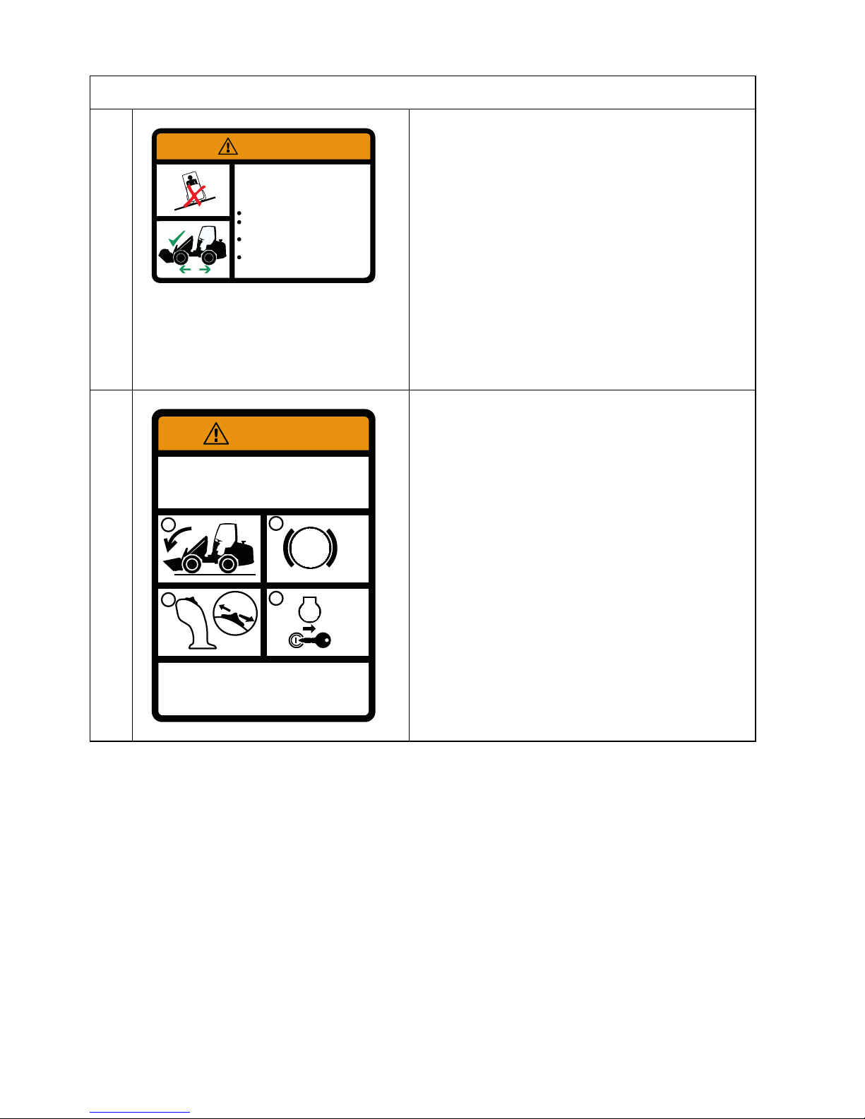
A Lift Point Decal
Located at the rear of the machine and near
the lift holes/rods near the top of the front
frame.
• Apply lift hooks only in these location,
See chapter “Commissioning”.
D-L
T
V
J-X-L-H
Q
N-R
B
C
G
E
E
K-M1
S
O
M2
A
5103008-16-A
Page 44

44
4.Safety
B WARNING: Do not modify ROPS; replace
damaged ROPS; wear seat belt;
NEVER REMOVE ROPS.
Located inside the ROPS structure.
• The protection offered by this ROPS will
be impaired if it has been subjected to
any modification, structural damage, or
has been involved in an overturn
incident, this ROPS must be replaced
after a roll-over. Seat belts must be
worn while operating vehicle.
C WARNING: Crush Hazard
Located on top of the articulation joint on
both sides.
• Keep away from machine when it is
being operated.
• Lock frames together when machine is
serviced or shipped.
D USE DIESEL FUEL ONLY!
Located next to the fuel filler neck.
E Tie-down point, located on lift arm (front,
both sides) and frame (rear, both sides).
• Only use tie-down points indicated on
loader when transporting loader.
F IMPORTANT
Located next to the fuel filler neck.
• Use ONLY diesel fuel according to one
of the following technical specifications:
• EN590
• ASTM D975 2D
• JIS K 2204.
See chapter “Maintenance”.
ANSI-Style and Common Safety Decal Location
The protection offered by this ROPS will be
impaired if it has been subjected to any
modification, structural damage, or has been
involved in an overturn incident. This ROPS
must be replaced after a rollover. Seat belts
must be worn while operating vehicle.
WARNING
5103008-03-A
NEVER REMOVE ROPS.
Keep away from machine when it
is being operated.
Lock frames together when
machine is serviced or shipped.
CRUSH HAZARD
5103008-06-A
WARNING
D
5103008-22-A
5103008-15-A
IMPORTANT
Use diesel fuel according to one of the following
technical specifications:
5103008-08-A
EN590
ASTM D975 2D
JIS K 2204
Page 45

45
4.Safety
G WARNING: Crush Hazard
Located on both side of the lift arm.
• Before operating, verify full
engagement of loader attachment
bracket locking pin to the attachment.
H USE HYDRAULIC FLUID ONLY!
Located next to the hydraulic fluid reservoir
filler neck.
J WARNING: Rotating Fan / Hot Surface
Hazards
Located on the right side of the firewall
inside the engine compartment.
On machines with air conditioning, located
on the back of the air conditioning enclosure.
• Keep hands out or stop engine.
• Do not touch hot engine or hydraulic
system parts.
ANSI-Style and Common Safety Decal Location
Before operating, verify full egagement of loader
attachment bracket locking pin to the attachment.
CRUSH HAZARD
5103010-12-A
WARNING
5103008-11-A
5103008-09-A
WARNING
AVOID INJURY
ROTATING FAN
Keep hands out or stop
engine.
HOT SURFACE
Do not touch hot engine or
hydraulic system parts.
Page 46

46
4.Safety
K WARNING: Avoid Injury or Death
Located on the left side of the firewall inside
the engine compartment.
On machines with air conditioning, located
on the back of the air conditioning enclosure.
• Keep safety devices working.
• Jump start per Operator Manual
procedure.
• Keep guards, screens and windows in
place.
• Do not smoke while fuelling or servicing
machine.
• Clean debris from engine compartment
daily to avoid fire. Keep fire
extinguisher nearby.
• Do not use hand to find hydraulic leaks.
• Escaping oil under pressure can be
invisible and penetrate skin.
• Allow radiator to cool before removing
cap. Loosen cap slowly to avoid burns.
L IMPORTANT
Located on top of the radiator inside the
engine compartment.
• Do not use ether or other starting fluids
to start this engine — warranty may be
voided.
M1 WARNING: Avoid Injury or Death
Located on the left side of the control column.
• ALWAYS wear seatbelt.
• No riders! Never use work tool as work
platform.
• Keep out from under lift arm unless lift
arm is supported.
• Operate only from operator’s seat.
• Prevent load rolling down lift arm onto
operator.
ANSI-Style and Common Safety Decal Location
AVOID INJURY OR DEATH
Keep safety devices working.
Jump start per Operator´s Manual procedure.
Clean debris from engine compartment daily to avoid
fire. Keep the fire extinguisher nearby.
Do not use hand to find hydraulic leaks. Escaping oil
under pressure can be invisible and penetrate skin.
Allow radiator to cool before removing cap. Loosen cap
slowly to avoid burns.
Keep guards, screens and windows in place.
Do not smoke while fueling or servicing machine.
Keep guards, screens and windows in place.
5103008-31-A
WARNING
Do not use ether or other
starting fluids to start this
engine.
Warranty may be voided.
IMPORTANT
5103008-08-A
AVOID INJURY OR DEATH
ALWAYS wear seatbelt.
No by-riders! Never use work
tool as work platform.
Keep out from under lift arm
unless lift arm is supported.
Operate only from operator´s
seat.
Prevent load rolling down lift
arm onto operator.
5103008-14-A
WARNING
Page 47
47
4.Safety
M2 WARNING: Avoid Overturn
Side stability is reduced when:
1) turning; 2) operating on rough terrain or
side slopes; and 3) carrying load raised.
• Carry load low.
• Do not exceed Rated Operating
Capacity.
• Avoid steep slopes and high speed
turns.
• Travel up and down slopes with heavy
end uphill.
N WARNING: Avoid Injury or Death
Located on the control column, facing the
operator.
Always follow “Mandatory Safety Shut down
Procedure.”
1) Lower equipment to ground.
2) Reduce throttle, apply parking brake.
3) Shift to neutral.
4) Stop engine, remove key.
ANSI-Style and Common Safety Decal Location
5103008-36-A
WARNING
AVOID OVERTURN
Side stability is reduced when: 1) turning;
2) operating on rough terrain or
side slopes; and 3) carrying load raised.
Carry load low.
Do not exceed Rated Operating
Capacity.
Avoid steep slopes and high speed
turns.
Travel up and down slopes with heavy
end uphill.
STOP
P
WARNING
AVOID INJURY OR DEATH
Always follow “Mandatory Safety Shutdown
Procedure.”
1) Lower equipment to ground.
2) Reduce throttle, apply parking brake.
3) Shift to neutral.
4) Stop engine, remove key.
5103008-07-A
1
2
3
4
N
Page 48

48
4.Safety
O WARNING: Avoid Injury or Death
Located on the control column, facing the
operator.
• Maintain 3-point contact during entry
and exit.
• Inspect work area; avoid all hazards.
• Look in the direction of travel. Keep
children and bystanders away.
• Start and operate machine only from
seat.
• Never carry riders. Do not lift personnel
in bucket.
• Operate only in well ventilated area.
• Keep away from electric power lines,
avoid contact.
• Do not wear loose clothing while
operating or servicing machine.
• Wear any needed Personal Protective
Equipment.
P WARNING: Crush Hazard
Located under the operator’s platform on
top of the left rear wheel well.
• Be sure lock mechanism is securely
engaged before working under ROPS/
FOPS.
• Read instructions for use in Operator
Manual.
ANSI-Style and Common Safety Decal Location
AVOID INJURY OR DEATH
5103008-13-A
Maintain 3-point contact during entry and exit.
Inspect work area; avoid all hazards.
Look in the direction of travel. Keep children and
bystanders away.
Start and operate machine only from operators seat.
Never carry riders. Do not lift personnel in bucket.
Operate only in well ventilated area.
Keep away from electric power lines, avoid contact.
Do not wear loose clothing while operating or
servicing machine.
Wear any needed Personal Protective Equipment.
WARNING
CRUSH HAZARD
Be sure lock mechanism
is securely engaged
before working under
ROPS / FOPS.
Read instructions for use
in Operator Manual.
5103008-10-A
WARNING
Page 49

49
4.Safety
Q WARNING: Read Operator Manual
Located behind the operator’s seat on the
document box cover.
• Read Operator Manual and all safety
signs before using machine.
• The owner is responsible to ensure all
users are instructed on safe use and
maintenance.
• Check machine before operating.
Service per Operator Manual.
• Contact dealer (or manufacturer) for
information and service parts.
R WARNING: Falling Object Hazard
Located under the parking hand brake lever.
• Falling-Object Protective Structure
(FOPS) must be installed if there is a
risk of falling objects.
S WARNING: Avoid Injury or Death
Located on the control column, facing the
operator.
• Hold on to the steering wheel if the
loader tips over.
• NEVER jump out the loader.
ANSI-Style and Common Safety Decal Location
5103008-35-A
WARNING
AVOID INJURY OR DEATH
Read Operator Manual and all safety signs
before using machine.
The owner is responsible to ensure all users are
instructed on safe use and maintenance.
Check machine before operating. Service per
Operator Manual.
Contact dealer (or manufacturer) for information
and service parts.
5103008-02-A
Falling-Object Protective
Structure (FOPS) must
be installed if there is
a risk of falling objects.
FALLING OBJECT HAZARD
WARNING
WARNING
AVOID INJURY OR DEATH
Hold on to the steering wheel if
the loader tips over.
NEVER jump out of the loader.
5103008-26-A
Page 50

50
4.Safety
T WARNING: Avoid Injury or Death
Located under the parking brake lever.
• When parked; driving or working the
doors must always be closed.
• NEVER remove the doors.
U WARNING: Avoid Injury or Death
Located under the parking brake lever.
• When parked; driving or working the
doors must always be closed.
• NEVER remove the doors.
V WARNING: Avoid Injury
Located along the door.
• By entry and exit of the operator keep a
safe distance.
• Maintain 3-point contact during entry
and exit. Do not grasp steering wheel
during entry and exit.
ANSI-Style and Common Safety Decal Location
AVOID INJURY OR
DEATH
When parked; driving or
working, the doors must
always be closed.
NEVER remove the doors.
WARNING
5103008-25-A
AVOID INJURY OR
DEATH
When parked; driving or
working, the doors must
always be closed.
NEVER remove the doors.
WARNING
5103008-24-A
WARNING
5103008-22-A
AVOID INJURY
By entry and exit
of the operator
keep a safe
distance.
Maintain 3-point
contact during
entry and exit.
Do not grasp
steering wheel
during entry and
exit.
Page 51

51
4.Safety
W WARNING: Avoid Injury
Located along the door.
• By entry and exit of the operator keep a
safe distance.
• Maintain 3-point contact during entry
and exit. Do not grasp steering wheel
during entry and exit.
X Oil specification
Y Break fluid specification
Z Escape route
AA Indicates the grease points
ANSI-Style and Common Safety Decal Location
WARNING
5103008-23-A
AVOID INJURY
By entry and exit
of the operator
keep a safe
distance.
Maintain 3-point
contact during
entry and exit.
Do not grasp
steering wheel
during entry and
exit.
CONSULT YOUR DEALER FOR INFORMATION
Engine Oil: Mobil Super 2000 X1 10W40
Hydraulic Oil: Mobil Nuto H46
Transmission Oil: Mobilube LS 85W90
Coolants: Coolant -26ºC (-14ºF)
5103008-37-A
CONSULT YOUR DEALER FOR INFORMATION
5103008-38-A
Oil Brakesystem: Mobil Nuto H46
According to:
DIN 54524 Part 3 HVLP
ISO 1158 HV
ISO Viscosity Class: 46 cSt
WARNING:
DO NOT USE STANDARD BREAK FLUID!
5103008-39-A
5103010-25-A
Page 52

52
4.Safety
SLOPES
CAUTION:
If possible, do not drive on slopes. Do not drive across slopes.
When you drive on slopes, there is a risk of injury due to these causes:
• The machine can tip over.
• There is less traction and braking force of the wheels which can cause unexpected movement of the machine.
Only drive on slopes in these conditions:
• The attachment is empty.
• The lift arm is in the lowest position.
• The maximum angle of the slope is not more than 11.3° (20%).
• You drive straight up and down the slope.
• The machine is unarticulated.
• You drive up and down the slope with the heaviest end uphill.
When you operate the machine, including loads, the maximum slope at maximum
load at the lowest speed is limited to 3° (5.3%). Steeper slopes are possible with
smaller loads, at your discretion and responsibility. The maximum angle of the
slope depends on these factors:
• The loading, weight, position and balance of the load.
• Your driving style and speed.
• Circumstances and the capacity of the surface, such as loose sand, and
humidity of the surface.
Stay at the ‘high’ side during transport on a slope.
When you load or unload the machine from a trailer, obey the instructions in the
chapter ‘Commissioning’.
SAFETY - HYDRAULIC PARTS
• Exposed hydraulic hoses could react with explosive force if struck by a falling
or overhead items. NEVER allow hoses to be hit, bent or interfered with.
Replace any hoses that are damaged.
• Keep unprotected body parts, such as face, eyes, and arms as far away as
possible from a suspected leak.
• Do not smoke or have any spark- or flame-producing equipment or materials in
the area while working on the hydraulic systems.
Page 53

53
4.Safety
• Do not attempt to loosen or disconnect any hydraulic lines, hoses, fittings, covers or caps without first relieving hydraulic circuit pressure. Relieve hydraulic
pressure by performing the Mandatory Safety Shutdown Procedure of the
machine, and then slowly loosening the hydraulic reservoir filler cap. Be careful not to touch any hydraulic components that have been in recent operation,
because they can be hot and cause burns.
• Do not work on hot hydraulic systems. Wait for the systems to cool. When fluids require changing, wait for fluid temperatures to decrease to a moderate
level before removing drain plugs.
• Prior servicing, the system has to be depressurized completely!
• Safety-critical parts must be periodically replaced. Replace hydraulic system
hoses as soon as they begin to show signs of deterioration, especially the
pump outlet lines. Replace hydraulic hoses every 6 years from the date of
manufacture (month or quarter, and year) is indicated on the hydraulic hoses.
• After cleaning the attachment, check all hydraulic oil lines for leaks, chafe
marks and damage. Tighten any loose connections and repair or replace parts
as necessary.
• Add hydraulic fluid to the attachment only in well-ventilated areas.
• Escaping fluid under pressure can be invisible and can penetrate the skin and
cause serious injury. If any fluid is injected into your skin, see a doctor at once.
Injected fluid must be surgically removed by a doctor or gangrene may result.
If your doctor is not familiar with this type of injury, ask him or her to research it
immediately to determine proper treatment.
Page 54

54
4.Safety
• Wear safety glasses, protective clothing and use a piece of cardboard or wood
when searching for hydraulic leaks. DO NOT USE YOUR HANDS! SEE
ILLUSTRATION.
Page 55

55
4.Safety
SAFETY PRECAUTIONS
CAUTION:
Risk of serious injury.
Read the operator manual of the Wheel Loader thoroughly before
using the machine. This way you know exactly how to operate the
Wheel Loader safely.
CAUTION:
Risk of serious injury.
For maintenance work: Stop engine, remove the ignition key and put
the Wheel Loader on the parking brake. See the operator manual.
This prevents dangerous situations which can arise if the Wheel
Loader suddenly moves or when the lifting arm suddenly goes down.
Also think about unforeseen actions by others.
CAUTION:
Risk of serious injury by collision.
Ensure that bystanders keep at least 10 meters (11 yards) distance
from the travel path of the Wheel Loader. Large bulky loads can
interfere with the driver’s sight.
CAUTION:
Risk of injury due to entrapment by moving parts.
Operate the controls only from the driver’s seat. Ensure that
bystanders keep clear within a radius of 4 meters (4.4 yards) from the
Wheel Loader.
5103010-13-A
Page 56

56
4.Safety
CAUTION:
Risk of serious injury.
Before driving, make sure you sit correctly in the driver’s seat
and always have your seat belt fastened. Make sure the
seat, pedals and your shoes are free of contaminants which
can cause accidents caused by slipping.
CAUTION:
Risk of serious injury when overloading the
Wheel Loader.
The load on the Wheel Loader must not weigh more than
indicated in section ‘Technical Data’. Make sure the tool is
evenly loaded and balanced.
CAUTION:
Risk of serious injury.
Hold the attachment approximately 30 cm (11.8 in) above the ground
when driving over the road.
CAUTION:
Risk of serious injuries on slopes.
The Wheel Loader is designed for working on flat and hard surfaces.
The maximum gradient is 3° at maximum load, driving with the lowest
speed. Larger inclinations are possible with smaller loads, at the
discretion and responsibility of the driver. Stay at the “high” side
during transport on a slope.
Page 57

57
4.Safety
CAUTION:
Risk of injury from involuntary movement.
Injury may result due to lack of traction and braking force of the Wheel
Loader. Never drive across a slope. Only drive straight up or down a
slope.
CAUTION:
Risk of serious injury when tipping over.
The Wheel Loader can tip over when riding on an uneven or damaged
surface. Only drive straight up and down a slope, never across. The
maximum angle of inclination to ride is highly dependent on:
• The loading, weight and balance of the load.
• The driving style and speed of the driver.
• Circumstances and the capacity of the soil (such as loose sand)
and soil humidity.
CAUTION:
Pay attention to your surroundings!
Wear clothes in which you feel good and in which you can move easily.
CAUTION:
Risk of hearing damage.
This Wheel Loader can produce sound louder than 80 dB(A).
The driver is therefore obliged to be wearing ear protection.
Page 58

58
4.Safety
CAUTION:
Risk of serious injury from entrapment or fall.
It is not allowed to lift or transport persons with or on the Wheel
Loader.
CAUTION:
Risk of serious injury from electrical power lines and other
conductors.
Keep a safe distance from electrically conductive objects such as
power lines, pylons and lamps. Nominal voltage safety distances:
• 0 to 1000 V: 1.0 m (1.1 yd)
• 1 kV to 110 kV: 3.0 m (3.3 yd)
• 110 kV to 220 kV: 4.0 m (4.4 yd)
• 220 kV to 380 kV: 5.0 m (5.5 yd)
• When unknown: 5.0 m (5.5 yd)
CAUTION:
Risk of serious injury.
The hydraulic system operates under high pressure. A
leaky hose, pipe or coupling can cause serious injuries.
Prior servicing, the system has to be depressurised
completely!
A high pressure jet (up to 400 bar (5802 psi)) easily
penetrates gloves, clothing and skin which causes serious injury and poisoning.
Page 59

59
4.Safety
CAUTION:
Risk of injury by burning.
The hydraulic components, hoses, piping, engine and exhaust are
very hot at operating temperatures.
CAUTION:
Risk of damage.
When hearing an unusual noise: Immediately shut down the engine and check the
Wheel Loader and the hydraulic system for leaks. Check the lift and tilt parts for
damage, cracks and bends. Lower lift arm before inspection!
CAUTION:
Prevent damage.
Tighten nuts and bolts periodically. See section ‘Maintenance’.
CAUTION:
Prevent damage.
Check daily:
• Fixings and hinges of the lift and tilt parts of the Wheel Loader
• The attachment bracket for damage and bends
• Lift and tilt cylinders
• The hydraulic system for any damage or leaks
CAUTION:
Risk of injury.
Ensure the Wheel Loader and its parts are fully and
correctly supported when doing maintenance. Make sure
the handbrake is applied.
Page 60

60
4.Safety
CAUTION:
Risk of crushing.
• Avoid entrapment by the fan of the radiator.
• Risk of burns from hot engine parts, radiator or exhaust.
CAUTION:
Fire hazard!
• Stay away from the fuel tank with cigarette lighter, match or other open fire.
• Only fill the fuel tank in a well-ventilated area (preferably in the open air).
• Keep the Wheel Loader free from combustibles.
CAUTION:
Fire hazard!
Danger in flammable working environment. The Wheel Loader produces hot
exhaust gases and possible sparks from the exhaust. Keep the Wheel Loader free
of combustible substances. Be aware of flammable substances in the environment
such as dust, straw etc.. The Wheel Loader can optionally be equipped with a
holder for a fire extinguisher.
CAUTION:
Risk of carbon monoxide (CO) suffocation.
People can be seriously injured when the exhaust gases are not sufficiently
removed. Always provide fresh air in the surroundings of the Wheel Loader.
Page 61

61
4.Safety
CAUTION:
Danger when charging battery.
An explosive gas is being formed during charging of the
battery. Cigarettes and open flames are prohibited! Only
charge the battery in a well-ventilated area.
When handling batteries:
• Avoid skin contact with battery fluid. Wear protective
clothing, such as safety glasses and gloves. The liquid is a highly corrosive
acid. Upon contact, wash immediately with soap and water.
• In case of contact with eyes, rinse immediately with running water for at least
10 minutes and immediately get medical attention. Provide sufficient water and
soap and make sure there is assistance in vocal range when performing work.
• Prevent shorting (sparking), ensure that no electrical connection between the
battery poles is made. Make sure that no metal objects touch the battery, causing a spark or short circuit with the possible consequence of explosion.
• Any conductor (metal) contacting both poles will get extremely hot. Remove
personal items such as rings, bracelets, necklaces and watches when handling batteries.
CAUTION:
Danger of personal injury.
One can be injured if the cable diameter or the electrical connection of the rectifier,
fuses, earth connection etcetera has not been carried out correctly.
Page 62

62
4.Safety
CAUTION:
Risk of serious injury!
Do not let the Wheel Loader be controlled by:
• Persons under the age of 16.
• Persons between the age of 16 to 18 years without
supervision from any (experienced) person over 18
years.
• Persons without Wheel Loader experience and without
supervision.
• Persons of who can be expected that they are not aware of the dangers of a
Wheel Loader, such as for example a temporary workforce.
The Wheel Loader may only be driven by experienced drivers who have read this
manual thoroughly and after you, the owner of Wheel Loader, have given a
complete instruction on the operation and safety of the Wheel Loader.
The owner of the Wheel Loader is responsible for the fact that only trained and
authorized persons are allowed to drive Wheel Loader.
CAUTION:
Risk of serious injury.
If safety instructions are not passed to other drivers, it can
lead to serious injury. Let other drivers at all times read this
manual thoroughly before they control the Wheel Loader.
Page 63

63
4.Safety
CAUTION:
Prevent injury.
Use of public roads with the Wheel Loader is NOT allowed, unless the Wheel
Loader is equipped with the country-specific “Roadway Package”, supplied by the
manufacturer. Driving on public roads with a loaded attachment (bucket, pallet fork
etc.) is NOT allowed.
Please note:
• The different dimensions and handling cause unexpected situations for other
road users. Driving on public roads should therefore be avoided as much as
possible.
• Driving on the highway is not permitted.
• When driving on public roads, the Wheel Loader is subject to the governmental and local traffic rules and requirements.
• In addition to the current insurance policies, an insurance for driving on public
roads may be required.
• The maximum speed of an earthmoving machine is 25 km per hour
(15.5 mph).
• Attachments should be protected. Read the manual of the attachment.
• The attachment should be in a position such that it will not interfere with the
driver’s sight or endanger other road users. Also make sure that the vehicle
lighting remains visible for other road users. Read the manual of the attachment.
CAUTION:
Risk of serious injury.
Adjust your speed according to road conditions.
• Make sure you always have control of the Wheel Loader.
• Reduce your speed on rough terrain and when taking sharp turns.
• Be especially careful when manoeuvring and reversing.
• Ensure a good overview of the work environment.
CAUTION:
Risk of injury.
When the safety icons are not (longer) clearly visible or legible, immediately apply
new decals (contact your dealer).
Page 64

64
4.Safety
CAUTION:
Risk of injury.
Maintenance and repair work may only be performed by professionals who are
approved by Tobroco Machinery LLC.
Only original and Tobroco Machinery LLC approved components are allowed to be
used on the Wheel Loader.
CAUTION:
Risk of injury.
The driver provides the limits for ‘safe working’ with the Wheel Loader. Do not take
any risks. Take care with obstacles, uneven terrain and in crowded areas.
CAUTION:
Risk of injury by falling load.
• The driver can be struck by falling objects.
• It is not allowed to stack and lift (multiple) objects or
loose cargo above the attachment’s height.
5103010-01-A
Page 65

65
4.Safety
CAUTION:
Risks when handling cargo.
Working with the Wheel Loader may entail additional risks. Through the load it is
also possible that driving characteristics and responsiveness of the Wheel Loader
is strongly influenced.
Therefore observe the following precautions:
• The load on the Wheel Loader must not weigh more than indicated in section
“Technical data”. Make sure the load in/on the tool is evenly balanced.
• Move the Wheel Loader with the tool up to 30 cm above the ground.
• Adjust your speed according to road and environmental conditions.
• Make sure you always have full control over the Wheel Loader.
• Reduce your driving speed on rough terrain and sharp turns.
• Be especially careful when manoeuvring and reversing.
• Provide a good overview on the work environment.
• The driver determines the limits for ‘safe working’ with the Wheel Loader.
• Do not take risks. Take care with obstacles, uneven terrain and crowded
areas.
• It is not allowed to transport (multiple) objects or loose cargo that protrudes
above the attachment. The Wheel Loader requires a (FOPS) safety roof or
cabin when using certain attachments. The Wheel Loader can tip over when
driving over uneven or damaged terrain. Moderate your speed.
• There is a risk of injury from involuntary movement due to lack of tension and
braking force of the Wheel Loader.
• Only drive straight up and down a slope. Do not drive across slopes.
CAUTION:
Danger of technical damage!
Never tilt the attachment bracket when driving
without attachment and with fully retracted lifting
arm. Especially when the Wheel Loader is
equipped with a special attachment bracket
(e.g. Euro bracket). This can severely damage
the tyre!
Page 66

66
4.Safety
CAUTION:
Danger of technical damage!
Welding activities should only be performed by qualified
personnel! Ensure supervision by qualified personnel
when welding on or nearby containers which contain
flammable materials! Contact your dealer if you have any
questions.
• Disconnect the positive terminal from the alternator
before starting any welding activities on the loader.
• Turn the main mass switch OFF.
• Attach the welding clamp as close as possible to the welding area.
• The welding current may not pass through any bolt, joint, gear or hydraulic cylinder.
• After welding, reconnect all the electrical connections and check their function.
Page 67

67
5. TECHNICAL DATA
Page 68

68
5.Technical data
DIESEL ENGINE
SSW
Make / Model Kubota D1105 Kubota D1105-T
Power 19 kW / 25 hp 24 kW / 33 hp
Rotational speed min. 1050 rpm 1050 rpm
Rotational speed max. 3000 rpm 3000 rpm
Displacement 1123 cm³ (68.5 CID) 1123 cm³ (689.5 CID)
Torq ue 72 Nm (53 ft-lbf)
@ 2100 rpm
88 Nm (65 ft-lbf)
@ 2050 rpm
Page 69

69
5.Technical data
GENERAL
D263S D332ST
Engine
Kubota diesel engine
Power train
Hydrostatic with automotive control
Drive hydraulics 84 l/min, 380 bar (22.2 gpm, 5511 psi)
Work hydraulics 42 l/min, 170 bar (11.1 gpm, 2466 psi)
Driving speed 12 km/h (7.5 mph)
Operating weight 1960 kg (4321 lb.) 1980 kg (4365 lb.)
Shipping weight 1480 kg (3263 lb.) 1500 kg (3307 lb.)
D263SW D263SW X-TRA D332SWT D332SWT X-TRA
Engine
Kubota diesel engine
Power train
Hydrostatic with automotive control
Drive hydraulics 84 l/min, 380 bar (22.1 gpm, 5511 psi)
Work hydraulics 42 l/min, 170 bar (11.1 gpm, 2466 psi)
Driving speed 12 km/h (7.5 mph)
Operating weight 1850 kg
(4079 lb.)
1900 kg
(4189 lb.)
1850 kg
(4079 lb.)
1900 kg
(4189 lb.)
Shipping weight 1500 kg
(3307 lb.)
1550 kg
(3417 lb.)
1500 kg
(3307 lb.)
1550 kg
(3417 lb.)
Page 70

70
5.Technical data
TIPPING LOADS
Tipping loads are measured in straight position, without additional counter weights.
Lifting arm drift
CAUTION:
The lifting device slowly drops. Depending on the load can be up to 1
cm (0.4 inch) per minute (measured at the point "U"). Keep this in
mind when parking the machine with a raised load.
D263S D332ST D263SW D263SW
X-TRA
D332SWT D332SWT
X-TRA
S 1040
(2293)
1060
(2337)
1040
(2293)
1500
(3307)
1040
(2293)
1665
(3671)
T 800
(1767)
810
(1786)
800
(1764)
1100
(2425)
800
(1764)
1100
(2425)
U 580
(1279)
590
(1301)
580
(1279)
750
(1653)
580
(1279)
750
(1653)
V 430
(948)
435
(959)
430
(948)
550
(1213)
430
(948)
550
(1213)
W 1375
(3031)
1400
(3086)
1375
(3031)
1500
(3307)
1375
(3031)
1500
(3307)
X 835
(1841)
850
(1874)
835
(1841)
900
(1984)
835
(1841)g
900
(1984)
Y 595
(1312)
615
(1356)
595
(1312)
650
(1433)
595
(1312)
650
(1433)
All values are displayed in kg (lb.)
Page 71

71
5.Technical data
DIMENSIONS
All dimensions in mm (in), measured on standard wheels.
Nº Dimension Standard X-TRA
A
Wheel base
1370 (53.94) 1420 (55.91)
B Total length 2670 (105.12) 2720 (107.09)
C Length with bucket 3360 (132.28) 3390 (133.46)
D Seat height 1140 (44.88) 1140 (44.88)
E Height 2230 (87.80) 2230 (87.88)
F Frame height 1550 (61.02) 1150 (45.28)
G Dump height 1830 (72.05) 1360 (53.54)
H Height of pivot point 2560 (100.79) 2070 (81.50)
I Height with bucket 3140 (123.62) 2640 (103.94)
J Rollback angle, low 41º 44º
K Rollback angle, high 52º 55º
L Dump angle 44º 41º
M Angle of departure 27º 27º
N Diameter of standard wheel 670 (26.38) 670 (26.38)
O Turning radius with bucket 2260 (88.98) 2470 (97.24)
P Outside turning radius 1900 (74.80) 2260 (88.98)
Q Inside turning radius 1040 (40.94) 1160 (45.67)
R Track width 815 (32.09) 800 (31.50)
S Total width 890 (35.04) 1100 (43.31)
Page 72

72
5.Technical data
E
D
M
A
B
C
N
J
I
H
G
F
K
L
O
P
Q
R
S
Page 73

73
5.Technical data
TRAILER
CAUTION:
Drive at walking pace with attached trailer.
CAUTION:
Driving with a trailer on public roads is NOT allowed.
TYRES
* Standard tyres
Max. vertical load coupling towing device. 100 kg (220 lb.)
Max. trailer weight unbraked. 750 kg (1653 lb.)
Type Tyre pressure Vehicle width in cm (inches)
bar kPa psi S SW SW X-TRA
7x12 AS 3.4 340 49.3 89 (35.0) * 89 (35.0) * ---
27x8.5-15 SKID 3.4 340 49.3 97 (38.2) --- ---
26x12-12 SKID 3.4 34 49.3 110 (43.3) 110 (43.3) 110 (43.3)
26x12-12 AS 3.0 300 49.3 110 (43.3) 110 (43.3) 110 (43.3) *
26x12-12 LG 3.0 300 49.3 110 (43.3) 110 (43.3) 110 (43.3)
27x10.5-15 AS 4.2 420 60.9 --- 103 (40.6) 103 (40.6)
10x75-15.3 AS 4.0 400 58.0 --- 101 (39.8) 101 (39.8)
300x60-12 TR 3.2 320 46.4 110 (43.3) 110 (43.3) 110 43.3)
31x15.5-15 TR 3.0 300 43.5 --- 123 (48.4) 123 (48.4)
31x15.5-15 AS 3.0 300 43.5 --- 123 (48.4) 123 (48.4)
Page 74

74
5.Technical data
Page 75

75
6. COMMISSIONING
Page 76
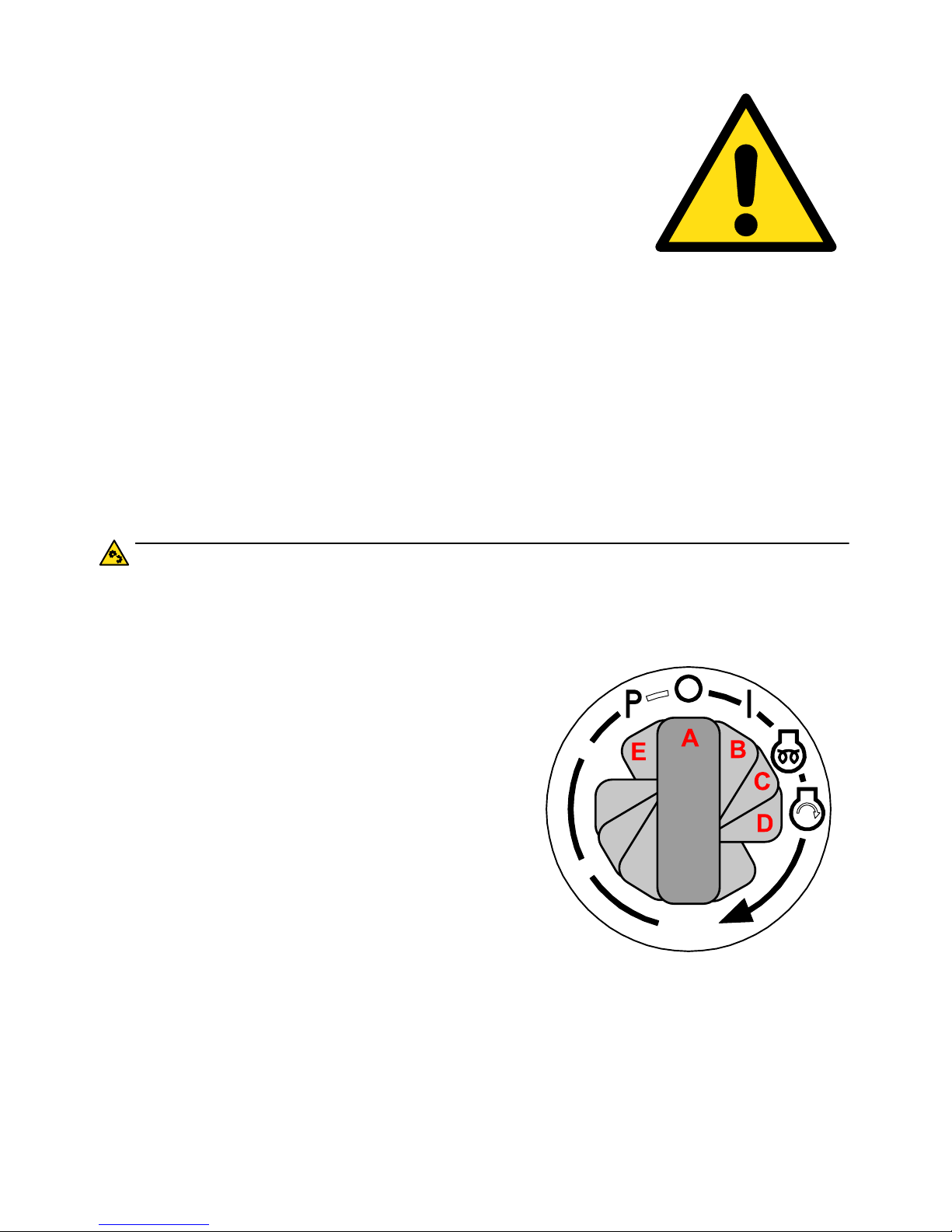
76
6.Commissioning
FIRST INSPECTION
• Before use, remove the articulation lock bar (transport
protection).
• The Wheel Loader is powered by a diesel engine. This
engine is equipped with an electric starter.
• Always check the oil levels before you start (see section ‘Maintenance’).
• Make sure the fuel tank contains sufficient fuel.
• Beware of fire! Stay away from the fuel tank with cigarette lighter, match or
other spark-inducing items. Keep the articulated loader free of combustibles.
• The Wheel Loader is top heavy and tilt sensitive. Especially with the loaded
tool in the upper position. Make sure the centre of gravity of the load to be
lifted is in the middle of the tool. Note that the ground under the Wheel Loader
is sufficiently load bearing and flat.
• Contact your dealer in case you have any questions.
IGNITION SWITCH
CAUTION:
Never press the accelerator all the way when you start. This causes
damage to the engine.
A. Stop engine.
B. Contact on.
C. Glowing (preheating, spring loaded).
D. Start engine (spring loaded).
E. Parking (unused).
Starting order:
1. Check whether the direction switch is set
to neutral.
2. Turn the ignition switch to position C and
hold this for about 5 seconds.
3. Turn the ignition switch to position D and
hold this position until the engine has
started.
4. Release the ignition switch; it will return to position B (contact on).
Page 77

77
6.Commissioning
DRIVING
Make sure you are aware of all hazards and operation of the Wheel Loader before
driving. Make sure you are familiar with the control devices of the Wheel Loader:
• Parking = parking brake
• Braking = left foot pedal
• Accelerating = right foot pedal (inching pedal)
Accelerator pedal
Upon depressing the accelerator pedal (1),
the coupling with the engine is automatically
made and the selected function is powered.
Releasing the accelerator pedal will
automatically slow down the Wheel Loader.
Inching pedal
Depressing the inching pedal (2) disconnects
the hydraulic drive. This way the vehicle
speed can be adjusted while keeping a
constant engine speed. This pedal also
functions as brake pedal.
1
2
Page 78
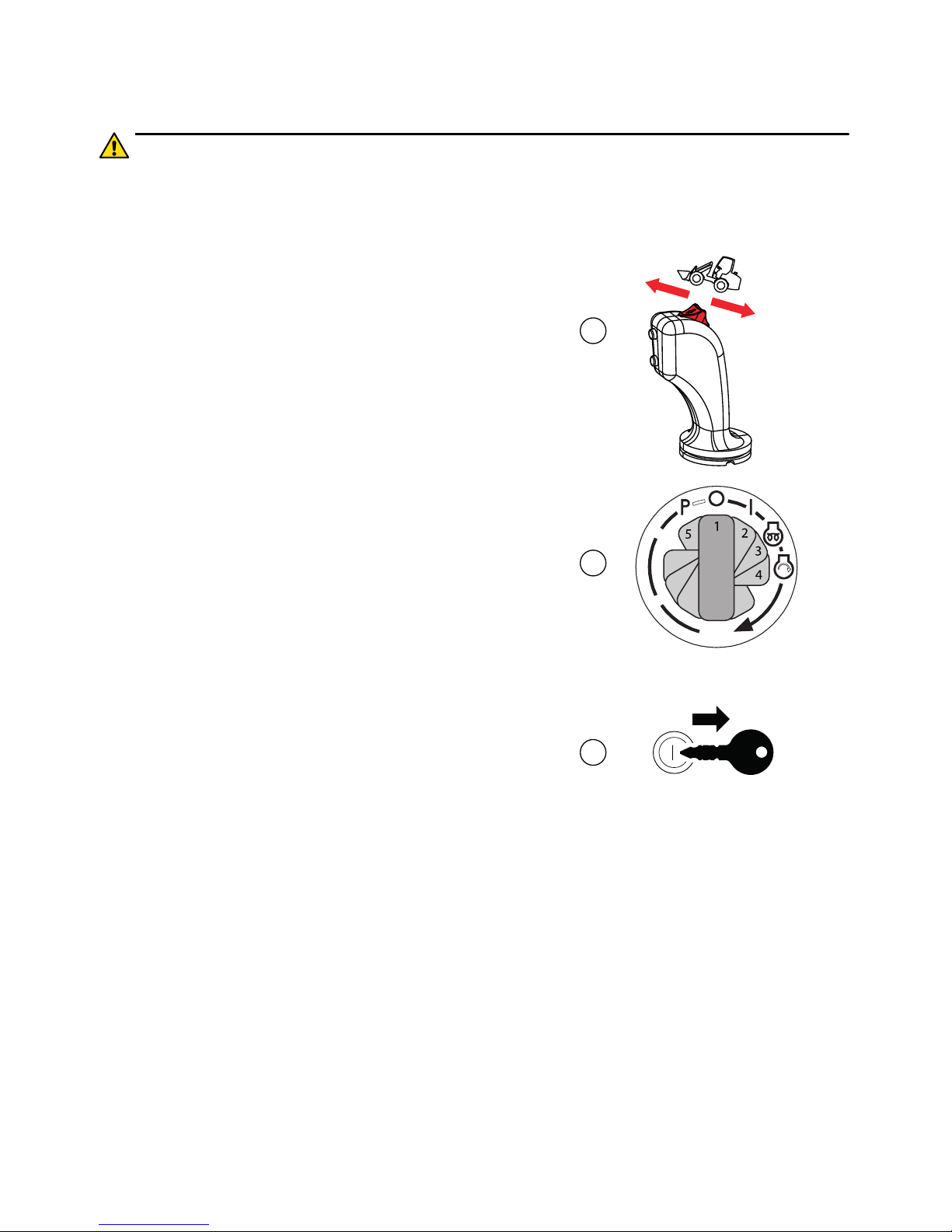
78
6.Commissioning
PARKING
CAUTION:
When parked remove the key out of the ignition switch.
Make sure you stop at the desired location.
1. Set the selector switch to “neutral” (N)
2. Turn the ignition switch to “O” and wait
until the engine has stopped.
3. Remove the key and take it with you.
N
F
R
2
1
3
Page 79

79
6.Commissioning
JOYSTICK
The joystick controls the following functions:
1. Tilt bucket upwards
2. Raise bucket
3. Tilt bucket downwards
4. Lower bucket
5. High / low gear (optional)
6. Forward (F) / neutral (N) / reverse (R)
7. Drive reset switch, 4th function electrical
(optional)
ATTACHMENT LOCKING
CAUTION:
Verify whether the attachment has been locked correctly.
mechanical lock
To (un)lock attachments; turn ball
valve (A) upwards.
• Locking: Move lever (B) to
the right to move the locking
pins (C) outward.
• Unlocking: Move the lever
(B) to the left to move the
locking pins (C) inward.
• Verify whether the attachment has been locked correctly.
N
F
R
3
2
4
1
6
A
C
B
Page 80

80
6.Commissioning
ATTACHMENT POSITION
When accessing public road:
1. Place the attachment approximately 15 cm above the road
2. Make sure that the protection is in place
3. Lock the position by turning the valves
Page 81

81
6.Commissioning
THIRD FUNCTION
To activate the 3rd function,
move ball valve (A) down.
Move the lever (B) to operate the
3rd function (C).
FOURTH FUNCTION
(ELECTRICAL)
(Optional)
• Press the button (1) on the
joystick and move joystick
left (2) or right (3) to operate
the 4th function (A).
B
C
A
A
2
1
3
Page 82

82
6.Commissioning
DASHBOARD
The following switches, instruments and warning lights are placed on the
dashboard:
1. Handbrake
2. Engine temperature
3. Direction indicator, left *
4. Alternator warning light
5. Reverse drive
6. Engine oil pressure
warning light
7. Engine temperature
warning light
8. Glow plug indicator
9. Direction indicator, right
10. Forward drive
11. Differential lock *
12. Rotating beacon switch *
13. Work light switch
14. Alarm light switch *
15. Lighting fuses
16. Fuel gauge
17. High beam *
18. Hour meter
19. Road lights *
20. Combination switch *
* optional
Once you turn on the ignition, all indicator lights will be lit. Once the engine is
running, the warning lights will go out.
ALTERNATOR WARNING LIGHT
When this warning light turns on, the alternator is
malfunctioning or the machine is not running!
Stop the engine and check the V-belt, if necessary contact
your GIANT dealer.
2
3
5
1
19
20
4 6
7
8 9
10
16
11
17
12
13
14
1518
Page 83

83
6.Commissioning
ENGINE TEMPERATURE
During normal operation the meter is pointing in the middle,
between 40 °C and 90 °C.
Stop the engine if the meter reaches the red zone. Check the
coolant level and the V-belt which powers the water pump.
Check cooling system for leaks.
ENGINE TEMPERATURE WARNING LIGHT
This warning light indicates that the engine is too hot. Stop the
engine, check the coolant level and fan belt. Check the
cooling system for leaks and/or refill with coolant. See section
“Maintenance”.
ENGINE OIL PRESSURE WARNING
LIGHT
This warning light indicates an insufficient oil pressure. Stop
the engine immediately. Check the oil level every day with the
dipstick and add oil if necessary. See section ‘Maintenance’.
COMBINATION SWITCH
(option, otherwise horn button)
1. Klaxon
2. Road lights off
3. Parking lights
4. Dipped-beam headlamps
5. Right turn signal
6. Left turn signal
7. Headlamp flasher
8. Main-beam headlamps
120
80
40
ºC
1
5
2
6
3
7
4
8
Page 84

84
6.Commissioning
SWITCHES IN CABIN
Switches located at the right side of
the seat
(Options with cabin)
• Main power switch (ground /
mass)
• Work lights rear (roof)
• Work lights front (roof)
• Front windshield wiper
ENGINE COVER
To open:
1. Stop the engine.
2. Unlock engine cover with
key.
3. Press the unlock button and
lift the engine cover by hand.
To Close:
1. Close the engine cover (you
will hear a “click”).
2. Lock engine cover with key.
STOP
Page 85

85
6.Commissioning
FUSES
CAUTION:
Danger! Fire hazard! Never replace a fuse wire with one of a higher
rating. This can cause a fire!
The Wheel Loader contains the following fuses, which are located at various
locations:
A. Fuses in steering column
B. Fuses on dashboard
Fuse Function Value (A) Fuse Function Value (A)
1 Ignition switch 15A 10 Direction indicators 10A
2 Dashboard
instruments
3A 11 Work light 15A
3 Rotation beacon 7.5A 12 Automotive lighting 7,5A
4 Reset, Fourth func-
tion, Differential lock
7.5A 13 Front position lamp 7,5A
5 Brake light, Parking
brake
10A 14 Front position lamp 7,5A
6 Joystick 10A 15 High beam 10A
7 Fuel feed pump 10A 16 High beam 10A
8 Stop solenoid 10A 17 Low beam 10A
9 Reversing alarm,
Horn
10A 18 Low beam 10A
AB
15A
10A
10A
3A
10A
10A
7,5A
10A
15A
7,5A
10A
7,5A
7,5A
10A
10A
7,5A
10A
10A
1
5
9
2
6
10
3
7
11
4
8
12
13
15
17
14
16
18
Page 86

86
6.Commissioning
C. Fuses at right side of the driver’s seat
D. Fuses at right side of the driver’s seat
Fuse Function Value (A) Fuse Function Value (A)
19 28 Switch for additional
equipment
15A
20 29 Switch for additional
equipment
15A
21 30 Front windshield
wiper
15A
22 31 Rear windshield
wiper
15A
23 32 Work light cab rear 15A
24 Lehner Polaro 33 Work light cab front 15A
25 Interior lighting 10A 34 12V Auxiliary 10A
26 Radio 10A 35 Ventilation 10A
27 Radio 10A 36 Spare
C
D
10A
15A
15A
10A
15A
10A
10A
15A
10A
15A
15A
25
29
33
26
30
34
27
31
35
28
32
36
19
21
23
20
22
24
Page 87

87
6.Commissioning
ENGINE OIL
CAUTION:
Check only with the Wheel Loader on a level surface and the engine is
turned off for at least 3 minutes. The oil level should be between the
markers. Refill if needed.
Adding engine oil
• Pull out the oil level dipstick
(B) and clean it with a lintfree, clean cloth,
• Reinstall the oil level dipstick
in the oil level pipe,
• Pull out the oil level dipstick
again and measure the oil
level (MIN - MAX),
• Oil level must be between the
MIN and MAX markings,
• If the oil level is to low,
remove the oil filler cap (A)
and fill with recommended oil
to the upper level mark,
• After adding oil, wait for more
than five minutes. It takes
some time for the oil to come
down to the oil pan,
• Pull out the oil level dipstick again and measure the oil level.
MAX
MIN
B
A
B
Page 88

88
6.Commissioning
TIRE PRESSURE
Tire pressure seriously affects fuel
consumption as well as steering and
driving characteristics. It also affects the
live span of tires and axes. See section
“Technical Data” for the correct tire
pressure.
WHEEL MAINTENANCE
Wheel bolts have to be re-tightened every
50 hours. For the right torque value, see
section “Maintenance”.
MAX
BAR
50 hr
Page 89

89
6.Commissioning
HYDRAULIC OIL LEVEL
CAUTION:
Check only when the engine is cold and the Wheel Loader is without
attachments with hydraulic functions.
The lifting arm is in lower position. Check the
oil level with the dipstick (under the hood, on
the left). The level must be between the MIN
and MAX mark. Refill when necessary (for oil
specifications see chapter “Maintenance”)
Page 90

90
6.Commissioning
GREASE POINTS
CAUTION:
Grease all indicated grease points daily. Oil all other moving parts
regularly, such as pedals, handles and hinges according to the intensity of use.
The Wheel Loader is to be lubricated DAILY at the following points:
1. Main pivot linkage
2. Boom cylinder
3. Boomerang
4. Locking pins
5. Tool bracket hinge
6. Lifting cylinder
7. Steering cylinder.
All lubrication points are indicated by a white decal with a
grease pump.
7
1
(2X)
2
3
2
5
(2X)
4
(2X)
3
36
5103010-25-A
5103010-25-A
Page 91

91
6.Commissioning
REFUEL
CAUTION:
Use only clean, high quality fuel for the Wheel
Loader. It is recommended to use an additional filter when refuelling.
Use your key to unlock and remove the fuel cap.
1. Fill the tank with fuel.
2. Close the fuel cap tightly and lock with key.
DRIVER'S SEAT
Adjust the seat to suit your personal
preference:
1. Horizontal adjustment
2. Armrest adjustment
3. Backrest adjustment
4. Suspension adjustment
2
3
1
4
Page 92

92
6.Commissioning
STEERING COLUMN
CAUTION:
Never adjust the steering column when the engine is running.
Adjust the steering column to suit your personal needs:
1. Take place on the driver's seat.
2. Pull the lever (A) towards you (1).
3. Tilt the steering column in position
(2).
4. Push the lever (A) away from you
(3).
A
1
3
2
Page 93

93
6.Commissioning
PRO-INCHING
CAUTION:
Do not use Pro-Inching on public roads! The machine can react differently than usual.
Pro-Inching is a combination of a
hand throttle and hand inching
and is extremely suitable for the
use of hydraulically powered
implements like sweepers and
mowers. Never use the ProInching function on public roads.
How does it work?
The hand throttle lever is used to
increase the engine speed. The
machine doesn’t move at this
moment. The accelerator pedal
automatically changes into a
driving pedal and allows you to
comfortably control the vehicle
speed. The remaining power is
used for powering the
attachment.
Page 94

94
6.Commissioning
ARTICULATION LOCK BAR
The articulation lock bar (A) must be mounted before transporting the Wheel
Loader (i.e. on a conveyor). This is also applicable when lifting the Wheel Loader.
Before commissioning the Wheel Loader you must remove the articulation lock
bar and place it in the appropriate holder.
AA
Page 95

95
6.Commissioning
TIE DOWN
CAUTION:
Lower the lifting arm for transport.
The Wheel Loader is equipped with eyelets for fixation to a trailer or other transport
platform.
Preparations
Make sure you have addressed all issues stated:
1. Place the Wheel Loader in a straight position on the
trailer.
2. Turn off the engine and apply the parking brake.
3. Mount the articulation lock.
4. Tie down the machine at the front and rear, using the
appropriate eyelets.
Page 96

96
6.Commissioning
LIFTING
CAUTION:
The Wheel Loader must be lifted evenly (horizontally) by using the
front and rear lifting points.
The lifting of the Wheel Loader is only permitted if the following conditions are met:
• The transport lock has been fitted correctly.
• The lifting device has sufficient lifting capacity (minimum operating weight).
• The lifting chains has sufficient lifting capacity (minimum operating weight).
• All attachments are disconnected.
• There is no loose lying object present on the Wheel Loader (danger of falling
objects during lifting).
• There are no bystanders near the Wheel Loader when lifting.
• A safe distance is kept from the machine when lifting.
Lifting points are marked with the following symbol:
5103010-23-A
Page 97
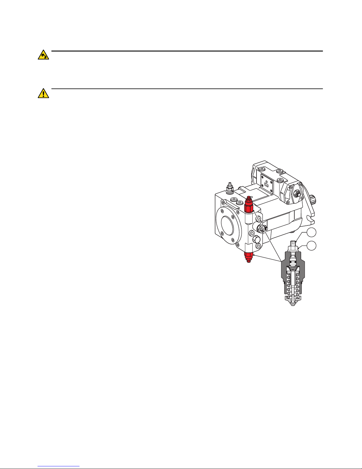
97
6.Commissioning
TOWING
CAUTION:
Towing the Wheel Loader is only allowed to remove it out of a danger
zone.
CAUTION:
The pump may become hot during towing!
Preparations
Before towing you need to open the bypass of main drive pump:
1. Turn off the engine.
2. Open the engine cover.
3. Fold the seat forward.
4. Turn nut (1) loose, making a half turn counter clockwise.
5. Loosen the hex bolt (2) clockwise until the
bolt touches the spring plate (this is the case
if you feel resistance).
6. Now turn the hex bolt (2) another half a turn
in. The spring is now pressed and the
bypass is activated.
7. Turn the nut (1) clockwise to secure with a
force of 22 Nm (16 lbf.ft) “hand tight”.
How to tow
• Mount the towing cable to the trailer coupling (back of machine) or the towing eyelets (front or rear).
• Tow with a maximum speed of 3 km/h (2 mph) “walking speed”
• Tow the articulated loader until the danger zone has been left, max. 200 m
(max 656 ft)
• Turn the bolt of the bypass back to the old position.
1
2
Page 98

98
6.Commissioning
LOADING - UNLOADING
The correct way to load and unload the Wheel Loader on and off a trailer.
Page 99

99
7. MAINTENANCE
Page 100

100
7.Maintenance
PERFORMING MAINTENANCE
Periodic maintenance should be performed by a licensed and qualified dealer. An
overview of all GIANT dealers can be found at www.tobroco-giant.us.
You can perform the following maintenance tasks yourself:
• Pivot points - greasing
• Wheel nuts - tightening
• Coolant - add or replace
• Engine oil - add or replace
• Engine oil filter - replace
• Hydraulic filter - replace
• Hydraulic oil - add or replace
• Air filters - clean or replace
• Radiator and fan - clean
• Check dashboards lights, dashboard instruments, lightning and battery cables
Contact your dealer in case of any doubt.
LIQUIDS
Overview
Engine oil SAE 10W-40 API CF // MIL-L-2104C // ACEA A2/B2,
A3/B3
Fuel Diesel EN 590 // GB 252 // ASTM D975 2-D //
JIS K 2204
Hydraulic oil VG 46 DIN 51524: part 3 // ISO 11158: type
HV
Axles and gearbox oil SAE 85W-90 LS API GL-5 // ZF TE-ML 05C/12C/16E
Brake fluid VG 46 DIN 51524: part 3 // ISO 11158: type
HV
Coolant -24°C (-12°F) Standard engine coolant
 Loading...