

Page 1

SELF-PRIMING ELECTRO PUMP
Edition
Date
Edited
Emitted
Approved
01
23/01/15
A. Dini
G. Ferrari
C. Gianneschi
Revision
Date
Updated
Emitted
Type of update
Date
Approved
BMA-M SERIES
OPERATING MANUAL FOR CENTRIFUGAL SELF-PRIMING
ELECTRICAL PUMP WITH INTEGRATED GRINDER.
1
Gianneschi Pumps and Blowers S.r.l.
www.gianneschi.net
Page 2

INDEX
1 INTRODUCTION .................................................................................................................................... 4
1.1 Preface ............................................................................................................................................. 4
1.2 Safety................................................................................................................................................ 4
1.3 Validity ............................................................................................................................................. 4
1.4 Guarantee ........................................................................................................................................ 5
1.5 Inspection of delivered items ........................................................................................................... 5
1.6 Instruction for transport and storage .............................................................................................. 5
1.6.1 Transport ................................................................................................................................. 5
1.6.2 Storage .................................................................................................................................... 7
1.7 Name Plate ....................................................................................................................................... 7
1.8 Spare Parts ....................................................................................................................................... 9
2 GENERAL ............................................................................................................................................. 12
2.1 Pump Description ........................................................................................................................... 12
2.2 Condition of use ............................................................................................................................. 13
2.3 Construction Feature ..................................................................................................................... 14
2.3.1 Pump Casing and Impeller ..................................................................................................... 14
2.3.2 Diffuser .................................................................................................................................. 15
2.3.3 Mechanical Seal ..................................................................................................................... 16
2.4 Self-priming action ......................................................................................................................... 17
2.5 GRinder. ......................................................................................................................................... 17
2.6 Materials ........................................................................................................................................ 18
3 INSTALLATION .................................................................................................................................... 18
3.1 Preliminary Operations .................................................................................................................. 18
3.2 Installation Guide lines ................................................................................................................... 18
3.2.1 Noise Level............................................................................................................................. 18
3.2.2 Piping Installation .................................................................................................................. 19
3.2.3 Suction Pipes ......................................................................................................................... 19
3.2.4 Delivery Pipes ........................................................................................................................ 19
3.3 Electrical Connections .................................................................................................................... 20
3.4 Pre Start-Up Check ......................................................................................................................... 21
3.5 Start- Up ......................................................................................................................................... 21
3.6 Stopping Pump ............................................................................................................................... 21
2
Gianneschi Pumps and Blowers S.r.l.
www.gianneschi.net
Page 3

4 MAINTENANCE ................................................................................................................................... 22
4.1 Cleaning. ......................................................................................................................................... 22
4.1.1 Cleaning the macerator. ........................................................................................................ 23
4.1.2 Cleaning the impeller. ........................................................................................................... 23
4.2 Repleacing impeller and Mechanical Seal ...................................................................................... 24
4.2.1 Replacing the impeller ........................................................................................................... 24
4.2.2 Replacing the mechanical seal .............................................................................................. 25
4.2.3 Adjusting Impeller Clearance ................................................................................................ 26
4.2.4 Adjusting Cutting Clearance .................................................................................................. 28
5 TROUBLESHOOTING ........................................................................................................................... 30
6 BRUSHES RePLACING (Only DC Version) ............................................................................................ 33
INDEX OF FIGURES.
Figure 1 Lifting instruction for pump unit. ..................................................................................................... 7
Figure 2 Example of pump name plate .......................................................................................................... 8
Figure 3 BMA-M exploded view ................................................................................................................... 10
Figure 4 Body pump internal view. .............................................................................................................. 13
Figure 5 Drain, fill and inspection port. ........................................................................................................ 14
Figure 6 Gap between Impeller and diffuser................................................................................................ 15
Figure 7 Check of correct gap between Impeller and diffuser ..................................................................... 15
Figure 8 Detail of mechanical seal ................................................................................................................ 16
Figure 9 Water-fill plug ................................................................................................................................. 17
Figure 10 Mechanical seal assembly ............................................................................................................ 26
Figure 11 Impeller face vanes must be within 0.2 – 0.3mm diffuser plane for most efficient operation. .. 27
Figure 12 Clearance between rotary and stationary cutter. ........................................................................ 28
Figure 13 Fixed cutter ring and rotary cutter. .............................................................................................. 29
3
Gianneschi Pumps and Blowers S.r.l.
www.gianneschi.net
Page 4

1 INTRODUCTION
This booklet describes operating procedures for centrifugal self-priming electrical pump “BMA-M” series.
These instructions must be followed to ensure safe and proper installation, operation and maintenance
of the machine. They should be brought to the attention of anyone who installs, operates or maintains the
machine or associated equipment. Ignoring these instructions may invalidate all applicable warranties.
1.1 PREFACE
This manual is intended for technicians and maintenance staff and for those who are in charge of
ordering spare parts.
The use of these machines must be made by qualified and experienced personnel, in full compliance with
local legislation.
This manual contains important and useful information for proper operation and maintenance of this
electrical pump. It also contains important instructions to prevent potential accidents and damage, and to
ensure safe and fault-free operation of this electrical pump.
NOTE
Read this instruction manual carefully before commissioning electrical pump. Familiarize yourself with
el/pump operations and strictly obey to the instructions. Keep this manual with care after reading, and
read as necessary.
The data published here comply with the most recent information at the time of going to press. However
they may be subject to later modifications.
Gianneschi Pumps and Blowers reserves the right to change construction and design of the products at
any time without being obliged to change earlier deliveries accordingly.
NOTE
The manufacturer declines all responsibility in case of accident or damage due to negligence or lack of
observance of instructions given in this booklet, or application in conditions not conforming to details
indicated on motor plate.
All responsibility is also declined for damage caused by improper use.
1.2 SAFETY
This manual contains instructions for working safely with electrical pump. Operator and maintenance
staff must be familiar with these instructions.
This manual has been prepared by Gianneschi Pumps and Blowers with the utmost care. Nevertheless
Gianneschi Pumps and Blowers cannot guarantee the completeness of this information and therefore
assumes no liability for possible deficiencies in this manual.
Gianneschi Pumps and Blowers reserves the right to change safety instructions.
1.3 VALIDITY
The instructions are valid for the following products: BMA-M
4
Gianneschi Pumps and Blowers s.r.l.
www.gianneschi.net
Page 5

1.4 GUARANTEE
The general guarantee is valid for 24 months from date of material shipment. To check validity of
guarantee, the customer must communicate to Gianneschi Pumps and Blowers both product serial number
and number/date of purchasing document (invoices). The guarantee shall naturally cover any defect in
construction of material manufactured by Gianneschi Pumps and Blowers.
Gianneschi Pumps and Blowers shall not be bound to any guarantee other than the guarantee accepted
by Gianneschi Pumps and Blowers. The guarantee will be immediately invalidated if:
Service and/or maintenance is not undertaken in strict accordance with instructions;
The electrical pump is not installed and operated in accordance with the instructions;
Necessary repairs are not undertaken by our personnel or are undertaken without our prior written
permission;
Modifications are made to the products supplied without our prior written permission;
The spare parts used are not original Gianneschi Pumps and Blowers parts;
The products supplied are not used in accordance with their nature and/or purpose;
The products supplied have been used amateurishly, carelessly, improperly and/or negligently;
The products supplied become defective due to external circumstances beyond our control.
All parts which are liable to wear are excluded from guarantee. Damages caused by normal or unusual
wear, wear caused by incorrect use or galvanic currents are not covered by the warranty.
1.5 INSPECTION OF DELIVERED ITEMS
Visually inspect electrical pump upon receiving it. Check for both obvious and hidden damage. If damage
is found, record all necessary information on the bill of lading and file a claim with the final carrier. Check to
be sure that all parts of the shipment, including accessories, are accounted for.
In case of irregularity, contact Gianneschi Pumps and Blowers immediately, signalling the nature of the
discrepancy.
CAUTION
In case of doubt about pump safety, do not use it.
1.6 INSTRUCTION FOR TRANSPORT AND STORAGE
1.6.1 TRANSPORT
The electrical pump is too heavy to be moved by hand. Use the correct transport and lifting equipment.
Usually electrical pump is shipped on pallet. Leave it on pallet as long as possible in order to avoid damages
and to facilitate internal transport.
CAUTION
When using a forklift always set the forks as far apart as possible and lift the package with both forks to
prevent it from toppling over! Avoid jolting the pump when moving it!
5
Gianneschi Pumps and Blowers S.r.l.
www.gianneschi.net
Page 6

CAUTION
Pump and components are heavy. Failure to properly lift and support equipment could result in serious
physical injury or damage to pumps. Steel toed shoes must be worn at all times.
Electrical pump must always be moved and transported in horizontal position. Prior to move the pump it
is mandatory to verify following items:
check the total weight of pump;
find centre of gravity of the pump;
find and check lifting points location.
For safe lifting to prevent material damages and/or personal injuries is recommended to use ropes or
belts properly positioned on the lifting eyebolts (if present).
CAUTION
When lifting electrical pump always use a proper lifting device, approved to bear the total weight of
the pump. Never go underneath a load that is being lifted!
WARINING
Lifting eyebolts fitted on single components of the unit pump assembly (pump or motor)
should not be used to lift total unit assembly.
If the electric motor is provided with lifting eyebolt, this lifting eyebolt is intended for maintenance
purpose of electrical motor only. The lifting eye is designed to bear the weight of electrical motor only!
It is not permitted to lift a complete pump unit by using only lifting eye bolt fitted on electrical motor!
During transportation, shocks, falls and humidity should be avoided.
6
Gianneschi Pumps and Blowers S.r.l.
www.gianneschi.net
Page 7

Figure 1 Lifting instruction for pump unit.
1.6.2 STORAGE
After receiving el/pump and inspected it, if it is not immediately installed on the plant, it is recommended
to repackage and store the unit indoors with vibration free, dust free and dry conditions.
Proper storage increases the service life of unit el/pump. For a proper storage proceed as follows:
Store electrical pump unit at indoor clean, dry and vibration free area;
Do not store el/pump in area with a temperature less than 5°C. For lower temperature it is
mandatory completely drain the pump from any liquids which freeze at temperature of around
0°C;
Fill body pump with rust-preventative liquid that is compatible with pump gaskets and
elastomers;
Drain the excessive liquid from the pump;
Rotate the shaft by hand in order to impregnate all internal surface with rust-preventative liquid;
Cover the pump with plastic sheet or similar protective material;
It is recommended that shaft is rotated periodically by hand to prevent binding of moving parts.
1.7 NAME PLATE
Pump name plate includes essential information required to identify pump type and technical data for
electrical motor and hydraulic performances.
Serial number is essential to uniquely identify the pump; this information is necessary to order spare
parts, to replace machine and also for field service inquires.
Before contact Gianneschi Pumps and Blowers company, it is strongly suggested to collect all information
listed on name plate, see Errore. L'origine riferimento non è stata trovata. and refer to Errore.
L'origine riferimento non è stata trovata..
7
Gianneschi Pumps and Blowers S.r.l.
www.gianneschi.net
Page 8

N°
Symbol
Description
1
MP
Machine serial number
2
Type
Pump Model
3 H Head (max min)
4 Q Delivery (min/max)
5
Mot
Type of motor (single phase, three phases, direct current)
6 V Rated Voltage
7 A Rated current
8
kW
Installed power
9
rpm
Revolution per minute
10
Hz
Rated frequency
11
I.C.L
Insulation class
12
Serv.
Service
13
IP
Index protection
14
Weight
Pump weight
Figure 2 Example of pump name plate
Table 1 Description of name plate fields
Gianneschi Pumps and Blowers S.r.l.
www.gianneschi.net
8
Page 9

1.8 SPARE PARTS
To correctly identify spare part to be order, please collect following data:
Pump model;
Pump serial number;
Position number;
Spare part name;
Quantity of spare parts to be order;
Exact reference who orders spare parts (company name or name/surname of person, address,
phone number, e-mail contact);
To facilitate selection of spare parts Gianneschi Pumps and Blowers can supplies two kinds of a pre-
defined spare parts kit, standard or extended spare parts kit. These kits include most usually recommended
spare parts for el/pump.
Manufacturer Address
Gianneschi Pumps and Blowers s.r.l.
via G. Pastore, n.° 19/21
55040 Capezzano Pianore (LU) – Italia
Tel.: +39 0584 365101 Fax.: +39 0584 969411
web site: www.gianneschi.net
e-mail: [email protected]
9
Gianneschi Pumps and Blowers S.r.l.
www.gianneschi.net
Page 10

Figure 3 BMA-M exploded view
10
Gianneschi Pumps and Blowers S.r.l.
www.gianneschi.net
Page 11

Item
Description
9
Spacer
13
Seeger ring
14
Mechanical seal
15
O-ring
16
Body pump screw
19
Diffuser screw
22
Electrical motor
23
Release Screw
24
Plug
26
Metal seal holder
27
Impeller
28
Spacer
29
Macerator blade
30
Diffuser
31
O-ring
32
Pump housing
33
Cover
34
Cover screw
35
Macerator body
36
Macerator impeller screw
37
Dowel pin
Standard Spare Part kit
14
Mechanical Seal
15-31
O-Ring
37
Dowel Pin
-
Capacitor (Only in 1Ph version)
Extended Spare Part kit
14
Mechanical Seal
15-31
O-Ring
37
Dowel Pin
-
Capacitor (Only in 1Ph version)
27
Impeller
30-35
Diffuser with macerator body
29
Macerator Blade
-
Sheems
Table 2 Spare parts name.
Table 3 Standard and extended spare parts kits.
11
Gianneschi Pumps and Blowers S.r.l.
www.gianneschi.net
Page 12

2 GENERAL
2.1 PUMP DESCRIPTION
Horizontal self-priming electrical pump at double volute with open impeller designed for rapid self-
priming with integrated grinder.
To ensure maximum corrosion and wear resistance; body pump, diffuser and impeller are made in high-
quality marine bronze alloy, while pump shaft is made in stainless steel. Cutting unit is made in hardened
AISI 630.
Cutting action takes place with the rotation of the cutter at rated rpm against the fixed cutter.
A separate air pump or any other equipment are not required to priming pump, thanks to a particular
shape of body pump, the priming would be secured even without no-return valve.
The pump unit is suitable in marine application to discharge waste water with faecal matter, domestic
waste water, waste water with toilet paper and grey water. In any case the water content has to be the
larger part of the handled fluid.
If there is a question regarding the intended use of the equipment, please contact Gianneschi Pumps and
Blowers before proceeding.
WARNING
“BMA-M” series electrical pump is not suitable to handle petrol (gasoline) and inflammables liquids.
WARNING
These units are not designed to handle liquids other than sanitary sewage.
If pump is used with contaminated liquids with heavy or abrasive materials, the warranty will be voided.
WARNING
It is important that the grinder rotates in the correct direction to give an efficient grinding operation. This
must be checked on installation and commissioning and after any maintenance has been carried out.
Failure to observe this may lead to mechanical and/or electrical overload or lead to pump failure.
12
Gianneschi Pumps and Blowers S.r.l.
www.gianneschi.net
Page 13

Figure 4 Body pump internal view.
Standard electrical pump configuration includes one of the following:
AC - three phases electric motor;
AC - single phase electric motor;
DC – electrical motor
Electric motors can be supplied for all main voltages and frequencies, either 50Hz and 60Hz.
2.2 CONDITION OF USE
Maximum operating conditions admitted for “BMA-M” series el/pumps are the following:
Maximum pressure admitted inside pump casing: 8 bar;
Maximum suction head: 8 mH2O;
Liquid temperature range: -5°C to +60°C;
Maximum ambient temperature: +50°C;
Voltage variation admitted: ± 5%;
Acoustic level: < 75db;
Starts: 20 per hour (max. admitted);
Abrasive liquids: not admitted;
Acid liquids: Min. PH=5;
Alkaline liquids: Max. PH=8;
Suction velocity not lower than 1 - 1.5 m/s
When waste water is handled the duty points (Qdp)in continuous operation lie within 0.7 to 1.2 x Qm
Example = Qm: 6m3/h 4.2 <Qdp <7.2
13
Gianneschi Pumps and Blowers S.r.l.
www.gianneschi.net
Page 14

To minimise the risk of clogging/hardening avoid duty points for continuous operation at very low speeds
and small flow rates (<0.7 x Qm). Qm is defined as the middle value of flow range reported in pump
datasheet and/or pump label.
The BMA-M is designed to discharge faecal matter, waste water and toilet paper only.
Using the appliance to discharge any other materials may cause the unit to fail.
Further details about the application possibilities of specific pump are mentioned in the order confirmation.
The following items should not be introduced into the pump either directly or through a kitchen waste
disposal:
Glass;
Metal;
Diapers;
Socks, rags or cloth;
Plastic objects (e.g., toys, utensils, etc.)
Sanitary napkins or tampons.
In addition you must NEVER introduce into the pump:
Explosives;
Flammable Material;
Lubricating Oil and/or Grease;
Strong Chemicals;
Gasoline.
Do not use the pump for purpose different from those for which it was delivered before contacting the
manufacturer Gianneschi Pumps and Blowers.
WARNING
Using a pump in a system or under system conditions (i.e. liquids, working pressure, temperature, etc..)
for which it has not been designed, may be hazardous for the user.
2.3 CONSTRUCTION FEATURE
2.3.1 PUMP CASING AND IMPELLER
Body pump is made of marine bronze with frontal inlet port and outlet port on pump top, the pump body
is closed by seal holder body on back side. A diffuser, with double volute design, ensures self-priming
action. On the diffuser inlet is installed the fixed cutter. On the bottom side of pump casing a drain hole is
located for drainage and cleaning purpose. The pump is fitted with open impeller at three blades. The
impeller is directly fixed on electrical motor shaft.
Figure 5 Drain, fill and inspection port.
14
Gianneschi Pumps and Blowers S.r.l.
www.gianneschi.net
Page 15

2.3.2 DIFFUSER
The innovative diffuser, designed by dual channel volute, has been thought for a fast priming.
Reduction of pump performances might be noted over the time by a decrease of maximum total head or
maximum delivery or by an increase of current absorption. Usually performances reduction can be an
indication of excessive gap between impeller and diffuser due to wear of the previous parts.
The clearance between volute and impeller should be always between 0.2 and 0.4mm. The sum of a and b
should not exceed 0.6mm.
Figure 6 Gap between Impeller and diffuser.
WARINING
The correct gap between impeller and diffuser can be checked by means of feeler gauge.
Figure 7 Check of correct gap between Impeller and diffuser
CAUTION
Improperly setting the clearance between impeller and diffuser can result in sparks,
unexpected heat generation and equipment damage.
15
Gianneschi Pumps and Blowers S.r.l.
www.gianneschi.net
Page 16

2.3.3 MECHANICAL SEAL
All pump types are equipped with leak-proof and maintenance-free mechanical seal. When air is
aspirated, the mating faces of the mechanical seal are hardly cooled or lubricated by the handled liquid. To
ensure adequate lubrication, the body pump must always be filled with handled liquid.
The life of a mechanical seal depends on various factors such as cleanliness of the liquid handled and its
lubricating properties. Due to the diversity of operating conditions it is not possible to give a data about life
time mechanical seal.
To assure maximum reliability an safely operation with el/pump, Gianneschi Pumps and Blowers
evaluates seal choices when pump is selected in accordance with technical requirements provided by
customer.
The mechanical shaft seal consists of two main parts the rotating part and the fixed part.
Figure 8 Detail of mechanical seal
CAUTION
Mechanical seal should never run dry.
Running mechanical seal dry, even if for a few seconds, can cause seal damages.
Physical Injury may occur if mechanical seal fails.
WARNING
It is recommended to check seal faces wear of mechanical seal every 1000 operating hours.
16
Gianneschi Pumps and Blowers S.r.l.
www.gianneschi.net
Page 17
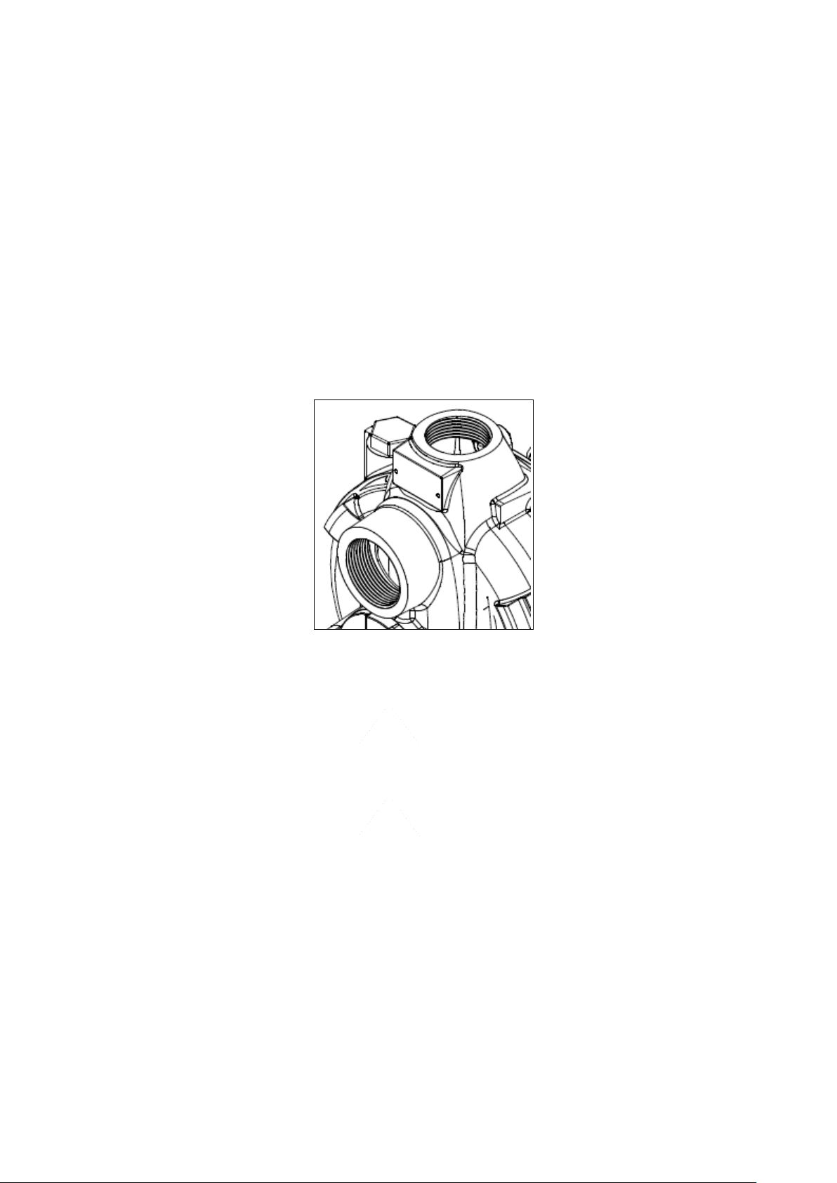
2.4 SELF-PRIMING ACTION
“BMA-M” series pumps are self-priming type pumps. Self-priming happens by means of strong liquid
turbulence generated inside the pump. Therefore pump casing must be previously filled-up with liquid to
be pumped.
At pump starting, the impeller creates a strong turbulence between suction and delivery side and this
physical phenomena causes the air passage from suction pipe toward delivery pipe.
The particular design of diffuser, with double channel, produces a quick self-priming action; moreover the
diffuser includes also wear plate.
It is mandatory to fill body pump with liquid before first starting up or after a long period of inactivity. To
fill body pump remove water-fill plug, located on upper side of pump casing and fill body pump with
priming liquid until overflow it. During filling operation, we recommend to slowly rotate the plug-in shaft by
hand in order to allow the air vent into the piping system. Refit water-fill plug and tighten it as required.
Figure 9 Water-fill plug
WARNING
It is mandatory that filling body pump operation is done before first start-up of the pump and each
time body pump is, or could be, empty to avoid any damage to internal parts of the pump.
WARNING
Operating the pump dry will destroy the pump seal. If the pump has been dry operated, stop engine
immediately and allow the pump to cool down. Subsequently proceed with filling body operation.
2.5 GRINDER.
Prior to entering the impeller casing, large solids are reduced in size by a cutting system to ensure passage
through the pump without clogging.
The cutter assembly is comprised of hardened AISI 630 components; a rotary cylindrical cutter directly
connected to the shaft and a fixed cutting ring fixed to the pump diffuser.
The rotary cutter is freely rotating within the fixed cutter and, when the pump is running, liquid including
any particles passes by the cutters, whereby the particles are ground by the cutters to fine pieces avoiding
clogging and eventually stoppage of the pump.
17
Gianneschi Pumps and Blowers S.r.l.
www.gianneschi.net
Page 18

2.6 MATERIALS
Standard “BMA-M” series pumps are totally made in marine bronze alloy suitable for sea water.
Body pump, impeller and diffuser are in bronze alloy, while shaft is in Stainless Steel AISI 316 made. Both
parts of cutting unit are made in AISI 630 hardened.
3 INSTALLATION
3.1 PRELIMINARY OPERATIONS
Before installation, ensure that mains power supply is grounded in accordance with local legislation and it
corresponds to electrical motor requirements, see detail on name plate § 1.7.
Check and verify that pipe connections are compliant with suction delivery ports of the pump.
Ensure that location and fluid handled is in according to what stated in § 2.22.2.
The end user has full reasonability for preparation of the foundation. Metal foundation should be painted
to avoid corrosion.
Foundations must be even and sufficiently rigid to withstand both static (weight) and dynamic forces of
unit pump and also to withstand possible short circuit forces.
3.2 INSTALLATION GUIDE LINES
Correct installation of electrical pump can be complex and it should be carried out only by qualified and
experienced personnel.
ATTENTION
During installing operation all regulations of safety and good practice must be followed. All installing
operation are carried out under full responsibility of the technician installer and/or final user of the unit.
For a proper installation of el/pump, we recommend to follow the instructions below listed:
Ensure sufficient space around electrical pump in order to allow dismantling operation for
maintenance purpose;
Install the pump in a dry and well ventilated location with room temperature ≤+ 50°C;
The machine must be placed on a solid and clean surface in horizontal position;
Install vibration dumpers between el/pumps and foundation, in order to reduce transmitted
vibration;
Before starting new plants, always clean thoroughly, wash and blow, tanks, pipes and connections.
3.2.1 NOISE LEVEL
The noise level of the pump is lower than 75 dB. However, the noise level of 75 dB may be exceeded in
some installations and at certain operating points on the performance curve. Make sure that you
understand the noise level requirements in the environment where the pump is installed. Failure to do so
may result in hearing loss or violation of local laws.
18
Gianneschi Pumps and Blowers S.r.l.
www.gianneschi.net
Page 19

3.2.2 PIPING INSTALLATION
All piping must be independently supported, accurately aligned and preferably connected to the pump by
a short length of flexible piping to reduce stress on the pump head.
Ensure that pipes are fully sealed with jointing compound to the pump ports.
Pumps are supplied with threaded ports.
Check that suction and delivery pipes are correctly connected to pumps ports.
All pipes and containers connected to the pump must comply with the regulations and must be cleaned,
tension- free and intact.
Never draw piping into place by forcing at the flanged connections of the pump. This may impose
dangerous strains on the unit and cause misalignment between pump and driver;
Install the pipes well anchored on their own supports near to inlet and outlet points of the pump to avoid
their transmitting any vibration;
The pump should not have to support the weight of the pipe or compensate for misalignment;
For flanged connections, use only fasteners of the proper size and material;
WARNING
The nominal diameter of the pipes and of the connections built into the system
shall be the same size or larger than the nominal inlet and outlet diameters of the pump.
To avoid wrong functionality on suction side, the suction pipe sizes must be at least
as large as the pump suction connection.
It is recommended to install a valve on delivery line. This valve is required to regulate flow passage
and/or to isolate the pump for inspection and maintenance service.
To reduce the water hammer phenomena it is suggested to install a dampening arrangement on the
piping.
3.2.3 SUCTION PIPES
The length of the suction pipe should be as short as possible. If suction pipe length exceeds 10 meters, or
if many concentrated losses due to elbows or section decrease along the pipe are present, it is suggested to
use a pipe with a diameter greater than diameter suction port of the pump ( suction pipe suction
port). Smaller diameters may cause losses of performances, while higher diameters may causes a low selfpriming capability.
Inside suction pipe, the fluid speeds recommended are up to 1.5 m/s. However, the speed shall not be
lower than 0.5 m/s to avoid deposits into the pipe.
The pipe must not trap air pockets that may cause intermittent pump operation. For this reason, suction
pipe must be completely air-tight, without “gooseneck” and with continuous upward slope toward pump
inlet. Avoid sharp bends as possible.
To avoid pump damaging it is suggested to install a strainer along suction line.
All curves, elbows, valves and fittings installed on suction pipe create pressure loss. For this reason we
suggest to verify if losses are not likely to jeopardize pump operation
A vacuum gauge is recommended where pump performance needs to be closely monitored as well a non-
returned valve and sluice valve.
3.2.4 DELIVERY PIPES
Delivery pipe should be air-tight.
19
Gianneschi Pumps and Blowers S.r.l.
www.gianneschi.net
Page 20

It is recommended to install isolation and check valve and manometer on delivery line. Isolation valve is
required for priming, flow regulation and service of the unit.
Cushioning devices should be fitted on delivery line protect the pump from pressure surge due to water
hammer phenomena.
Delivery pipe diameter shall be equal to diameter of delivery port of the pump.
3.3 ELECTRICAL CONNECTIONS
WARNING
Electrical connections must be made exclusively by qualified personnel in accordance with instructions
from electrical motor manufacturer or other electrical components and it must follow rules of local
National Electrical Code
It is recommended that electric motors and eventual connected accessories must be protected against
overloading by means of circuit breakers and/or fuses.
Circuit breakers and fuses must be sized in accordance with the full load amperage declared on motor
nameplate. It is recommended to install electrical breaker near the pump for emergency situations.
Prior to connecting the electrical wiring, turn the pump shaft by hand to make sure that it rotates freely.
Connect the electrical wiring in accordance with local electrical codes. To be sure to connect to ground
electrical motor.
Make certain the power settings on the pump match your power source
before attempting to operate the pump.
Motor connection should be as indicated on the motor tag (frequency, voltage, poles and max
consumption).
It is mandatory to verify that sense of rotation of electrical motor is the same as sense direction of
rotation indicated by red arrow adhesive label present on the pump.
WARNING
Please be aware that rotation in the wrong direction and/or pump
running dry may cause severe pump damage.
If the sense of rotation is not correct, please immediately modify it following below instructions:
Incorrect rotation of three phases electrical motor:
The terminals of the power cable are marked with the IEC international codes. Their correct
connection to the L1(u), L2(v), L3(w) line ensures that the electric pump turns in the right
direction. The sense of rotation of the three phases electrical motor can be reversed by switching
any two phases;
Incorrect rotation of single phase electrical motor:
Wire the motor according to electrical scheme attached in the terminal box cover. In the unlikely
event that the rotation is still incorrect, contact Gianneschi Pumps and Blowers;
20
Gianneschi Pumps and Blowers S.r.l.
www.gianneschi.net
Page 21

Incorrect rotation of direct current electrical motor:
The sense of rotation of DC electrical motor can be reversed by interchanging two polarities.
3.4 PRE START-UP CHECK
Prior to starting the pump it is essential that following checks are made:
Electrical Pump properly secured to the base plate;
All fasteners are tightened as required;
Fill the body full of water
Check that the pump rotation is correct;
Check the electric connections and the proper setting for overloads. Do not start the electric-
driven pump with unconnected cables, motor terminal box not protected or without proper
protection against electrical accident;
Rotate the shaft by hand to be certain that all rotating parts move freely, and that there are no
foreign objects in the pump.
3.5 START- UP
Before starting up the pump check that all directives on positioning and connections are complied. In
detail verify that all suction and discharge valves are open. Be sure that discharge pipe is vented and
suction pipe is submerged into liquid to be pumped.
WARNING
Fill body pump with compatible liquid with liquid handled through fill hole.
To carried out filling of body pump refer to § 2.4.
Never run pump dry!
CAUTION
Never run the pump against a closed discharge valve.
Continued operation against a closed discharge could damage the pump.
The pump should be primed in three minute. After pump is started-up, be sure that the liquid is primed
and that the pump runs regularly. If after 5 minutes the pump does not prime, immediately stop it and
consult troubleshooting section.
3.6 STOPPING PUMP
To stop electrical pump:
Switch-off circuit breaker in order to shutoff power supply to electrical motor;
Shut-off supply and suction and discharge lines
21
Gianneschi Pumps and Blowers S.r.l.
www.gianneschi.net
Page 22

WARNING
Never pressurize the plant with pump stopped.
In case of needed to pressurize the plant with the pump stopped, close both check valves
(on suction and delivery pipes) in order to isolate the pump from the plant.
4 MAINTENANCE
A routine maintenance program can extend the life of your pump.
Make sure to keep maintenance records. These records will help pinpoint potential problems and causes.
CAUTION
Before carry-out maintenance operation, take care that electrical pump is disconnected from power
source and avoid that electrical motor is started while you are working in the pump. This is important
especially for electric motor with remote control.
WARNING
For warranty service, electrical pump must be delivered to Gianneschi Pumps and Blowers company or
to an authorized centre. If electrical pump is opening by unauthorized centre the warranty will be
invalidated.
After stopping and secured the machine, close all valves on both suction and delivery pipes.
Drain body pump through the draining plug.
4.1 CLEANING.
The solids found in wastewater, for the intended use of BMA-M pump, are organic and often consist of
long and stringy shapes, such as fibres. Even if strongly not recommended the wastewaters could also
contain an high amount of synthetic cloth and artificial fibres, many consumers flush these products down
the toilet, thus adding synthetic fibres to the wastewater stream.
Household cleaning products, such as tissues, wipes, and dishcloths, should be disposed of in the trash or
compost..
Soft, strong, and elongated objects in wastewater are fed into the pump; some of these (organic or
artificial) will meet a leading edge. The fibres tend to wrap around the edge and fold over on both
macerator and impeller, the pump continues to operate but with reduced performance and increased
power consumption (soft or partial clogging.)
For the above reasons, according to the use rate, the pump must be periodically cleaned.
WARNING
Danger of cuts or amputation. When the inspection cover is removed
for cleaning purposes, the cutting elements are easily accessible.
Never introduce your fingers inside the pump and as there is a risk of injuries
due to contact with the impeller and macerator.
22
Gianneschi Pumps and Blowers S.r.l.
www.gianneschi.net
Page 23

WARNING
In order to avoid infection maintenance work should only be carried out using protective gloves.
Wear safety clothing and a protective mask, if required.
4.1.1 CLEANING THE MACERATOR.
The impeller should rotate easily together with the shaft. If that is not possible the pump might be
blocked. If a blockage can be seen on the suction side of the diffuser after disassembly the inspection port
(#33) or the pump body (#32), remove it by hand. After removal of the blocking the pump can be
reassembled, filled and started up again.
1. Fully disconnect the unit from the electrical supply and secured the machine against accidental
start;
2. Close the isolation valve on both inlet and outlet pipes;
3. Drain the unit using the draining plug;
4. Remove the inspection cover;
5. Thoroughly clean the pump by clean water to remove deposits and caking;
6. Manually rotate the impeller/macerator assembly on the opposite direction of rotation (on the
back of electrical motor there is a hexagonal socket that allows to rotate the pump shaft by an
allen key (#23);
7. Remove fibre and deposits, eventually not removed by the water, from the fixed cutter by an
appropriate tool, paying particular attention to do not damage machined surfaces;
8. Thoroughly clean the pump by clean water. Clean all machined surfaces;
9. Ensure the impeller freely rotates, with allen key (#23. Note: the electrical motor will offer some
resistance;
10. Assemble the unit fully and reinstall.
4.1.2 CLEANING THE IMPELLER.
To clean impeller from filamentous materials it may be sufficient to rotate the pump for a few turns in
opposite direction of rotation by hand and start the pump for few seconds in the right direction of rotation.
This operation may be repeated 2 or 3 times:
1. Fully disconnect the unit from the electrical supply and secured the machine against accidental
start;
2. Close the isolation valve on both inlet and outlet pipes;
3. Drain the unit using the draining plug (#24);
4. Remove the inspection cover (#33);
5. Thoroughly clean the pump by clean water to remove deposits and caking;
6. Replace draining plug and inspection cover;
7. Fill the pump body with clean water through the filling plug;
8. Rotates by hand for a few turns in opposite direction of rotation (by means the plug socket on
pump shaft #23);
9. Open the insulation valves;
10. Start the pump for few seconds according to §3.4 and §3.5;
11. If needed repeat from point 8 to 10.
If the pump is used only occasionally it should be cleaned after each operation by flushing with clean water
to eliminate deposits and caking.
If the impeller does not easily rotate after the normal cleaning the impeller could be blocked.
To remove any blocking from the impeller proceed as follow:
23
Gianneschi Pumps and Blowers S.r.l.
www.gianneschi.net
Page 24

1. Fully disconnect the unit from the electrical supply and secured the machine against accidental
start;
2. Close the isolation valve on both inlet and outlet pipes;
3. Drain the unit using the draining plug (#24);
4. Remove the inspection cover (#33);
5. Thoroughly clean the pump by clean water to remove deposits and caking;
6. Unscrew the six screws (#16), and remove the pump housing (#30);
7. Unscrew the three fixing screws (#19) remove the diffuser (#30);
8. Remove fibre and deposits from the impeller, clean all machined surfaces ;
9. Remove fibre and deposits, eventually not removed by the water, from the fixed cutter;
10. Thoroughly clean the pump by clean water;
11. Ensure the impeller freely rotates. Note: the electrical motor will offer some resistance;
12. Re-assemble the unit fully and reinstall.
WARNING
Be sure O-rings are in place before replacing all components.
4.2 REPLEACING IMPELLER AND MECHANICAL SEAL
4.2.1 REPLACING THE IMPELLER
Below instructions, should be carry out to correctly disassemble the pump in order to execute overhaul
operation to replacement of impeller and/or mechanical seal:
WARNING
Even a worn impeller and/or pump housing can have very sharp edges.
Wear protective gloves.
1. Fully disconnect the unit from the electrical supply and secured the machine against accidental
start;
2. Close the isolation valve on both inlet and outlet pipes;
3. Drain the unit using the draining plug (#24);
4. Remove the inspection cover (#33);
5. Thoroughly clean the pump by clean water to remove deposits and caking;
6. Unscrew the six fixing screws (#16), and remove the pump housing (#32);
7. Unscrew the three fixing screws (#19) and remove the diffuser (#30);
8. Unscrew the fixing screw (#36) and washer. Remove the rotating cutter (#29), the dowel pin
(#37) and the impeller (#27); For remove the impeller it’s necessary rotate in the opposite
direction the back release screw (#23)
9. Remove from the old impeller the seal, refer to section § 4.2.2 for seal replacement;
10. Clean and lubricate the shaft;
11. Replace the worn components and reassembly all other components; For grinder cantering see
§4.2.4
12. Thoroughly clean the pump;
13. Ensure the impeller freely rotates. Note: the electrical motor will offer some resistance;
14. Check the clearance between impeller (#27) and diffuser (#30) according to § 4.2.3;
15. Check the clearance between rotating cutter (#29) fixed cutter (#35) according to § 4.2.4.
24
Gianneschi Pumps and Blowers S.r.l.
www.gianneschi.net
Page 25

4.2.2 REPLACING THE MECHANICAL SEAL
Should the mechanical seal require replacement, proceed as follows and refer to Figures 10.
Carefully clean the seal cavity in the pump, making sure the area is free of dirt, corrosion and pitting that
might interfere with the fixed seat seal.
WARNING
Mechanical seal must NEVER RUN DRY,
the absence or lack of flushing will cause seal damage and reduction of operating life
1. Fully disconnect the unit from the electrical supply and secured the machine against accidental
start;
2. Close the isolation valve on both inlet and outlet pipes;
3. Drain the unit using the draining plug (#24);
4. Remove the inspection cover (#33);
5. Thoroughly clean the pump by clean water to remove deposits and caking;
6. Unscrew the six fixing screws (#16), and remove the pump housing (#32);
7. Unscrew the three fixing screws (#19) and remove the diffuser (#30);
16. Unscrew the fixing screw (#36) and washer. Remove the rotating cutter (#29), the dowel pin
(#37) and the impeller (#27); For remove the impeller it’s necessary rotate in the opposite
direction the back release screw (#23)
8. Remove the rotating seal part from the impeller;
9. Remove the stator from the seal holder seat;
10. Carefully clean the seal cavity in the seal holder, making sure the area is free of dirt, corrosion
and pitting that might interfere with the fixed seat seal;
11. Wash your hands after cleaning the pump and before opening up the new mechanical seal kit;
12. Clean and lubricate the shaft;
13. Wet rubber portion of the seal seat with a light coating of soapy water;
14. Press seal stator squarely into seal seat in seal holder. Avoid scratching the polished surface. If
seal seat will not position properly, place a cardboard washer over the polished surface and use a
piece of pipe to press in, firmly but gently;
15. After seal stator is in place, dispose of cardboard washer. Check that seat is clean and has not
been marred;
16. Using a clean cloth, wipe the shaft and make certain that it is perfectly clean;
17. Wet the inside rubber portion of the new seal cartridge with a light coating of soapy water. Slide
cartridge onto impeller until cartridge meets impeller plane surface.
18. Reinstall impeller key;
19. Reinstall any impeller shims that have been removed, refer to section entitled “Adjusting Impeller
Clearance”;
20. Replace the impeller and the rotating cutter onto the shaft motor;
21. Tighten lock bolt until impeller is seated against shims;
22. Ensure the impeller freely rotates. Note: the electrical motor will offer some resistance;
23. Reassemble the diffuser (#30);
24. Check the clearance between impeller (#27) and diffuser (#30) according to § 4.2.3;
25. Check the clearance between rotating cutter (#29) fixed cutter (#35) according to § 4.2.4;
26. Reassemble the pump body.
CAUTION
The precision lapped faces on the mechanical seal are easily damaged.
25
Gianneschi Pumps and Blowers S.r.l.
www.gianneschi.net
Page 26

Handle your replacement seal carefully.
CAUTION
Do not use metal tools to install any component of the seal assembly.
Do not touch any mating parts of the mechanical seal with your bare hands.
Do not allow any lubricant to get on the mating surfaces of the seal.
Figure 10 Mechanical seal assembly
WARNING
Components with sharp edges risk of cutting or shearing injuries!
Always use appropriate caution for installation and dismantling work.
Wear work gloves.
4.2.3 ADJUSTING IMPELLER CLEARANCE
After a large number of working hours, it may be necessary to adjust the clearance between the impeller
and the diffuser. When the clearance between the impeller and the diffuser volute exceeds 0.3mm at the
face of the impeller, it may be necessary to take corrective action. The increased clearance can cause
lengthened priming times and reduce pumping capacity. If the impeller is badly worn, it is recommended
that the impeller be replaced.
Normally, new pump clearances can be restored by simply shimming behind the impeller. This clearance
should be checked at least once per year and more often if water-containing abrasives are being pumped.
26
Gianneschi Pumps and Blowers S.r.l.
www.gianneschi.net
Page 27

1. Loosen the six screws (#16);
2. Remove the pump housing (#30);
3. By means a feeler gauge measure the clearance between impeller (#27) and diffuser (#30), quote
”b” in Figure 11 ;
4. Loosen the three screws (#19);
5. Remove the diffuser (#30);
6. By means a feeler gauge measure the clearance between impeller (#27) and seal holder (#26),
quote “a” in Figure 11;
7. The quotes “a” and “b” must be between 0.2 and 0.4mm, the sum “a + b” must be not greater than
0.6mm;
8. If one of the two above conditions is not respected the clearance must be restored by means the
shims (supplied in spare parts kit.) If impeller, seal holder and diffuser are badly worn they must be
replaced;
9. Loosen the four fixing screws (#13), ;
10. Add one or two shims to the shim pack to balance the wear, each shim in spare parts it is 0.2mm
thick;
11. Reassemble the components and measure again the quote “a” and “b”;
12. Once the clearances are restored, reassemble all parts.
Figure 11 Impeller face vanes must be within 0.3mm diffuser plane for most efficient operation.
WARNING
Components with sharp edges risk of cutting or shearing injuries!
Always use appropriate caution for installation and dismantling work.
Wear work gloves.
27
Gianneschi Pumps and Blowers S.r.l.
www.gianneschi.net
Page 28

WARNING
Be sure all O-rings are in excellent condition without cuts or nicks,
and replace them if not in excellent condition.
4.2.4 ADJUSTING CUTTING CLEARANCE
Using a suitable tool such as a feeler gauge, you can measure the cutting gap between the rotary cutter and
fixed cutter. If the cutting gap has become larger than 0,4 mm due to wear, it cannot be corrected and it
must be replaced.
Clearance (S) must be >0.4mm to obtain efficient grinding when pump is put back in service.
Figure 12 Clearance between rotary and stationary cutter.
Replacing Grinder Parts:
If the cutting gap has become larger than 0,4 mm due to wear, it cannot be corrected and it must be
replaced. If necessary to replace grinder parts because of wear or to inspect for clogging:
28
Gianneschi Pumps and Blowers S.r.l.
www.gianneschi.net
Page 29

1. Unscrew the six body pump screws (#16);
2. Remove the pump housing (#30) Note: if checking for clogging, these parts can now be cleaned
without removing them from the shaft. ;
3. By means a feeler gauge measure the clearance between rotary (#29) and fixed cutter (#35), quote
”S” in fig XXX;
4. Unscrew the macerator rotary screw (#36) and remove the rotary cutter (#29);
5. Replace the rotary cutter with a new one (#29) paying attention to insert the dowel pin (#37) in
both impeller (#27) and rotary cutter (#29);
6. Fix the rotary screw by fixing screw and washer (#13);
7. Replace the diffuser (#30) and fixed cutter (#35) with a new one (these component are supplied
coupled as standard);
8. By means a feeler gauge check the clearance between rotating cutter and fixed cutter. Clearance
(S) must be > 0.4mm), measure the clearance at least in 3 points equally spaced of 120 degree
around the rotary cutter perimeter;
9. Slightly tighten screws (#19) keeping the radial clearance between rotary and fixed cutter in the
range 0.25 - 0.4mm;
10. Manually rotate the impeller/macerator assembly (on the back of electrical motor there is a
hexagonal socket that allows to rotate the pump shaft by an allen key) to check interference
between fixed and rotating components;
11. Tighten screws (#19);
12. Replace the pump body and tighten the six fixing screw (#16.)
IMPORTANT:
Be sure that both three screws are tightened or loosened of the same amount.
By a feeler gauge or metal sheet of calibrated thickness check that
rotating cutter is centred in fixed cutter.
Figure 13 Fixed cutter ring and rotary cutter.
29
Gianneschi Pumps and Blowers S.r.l.
www.gianneschi.net
Page 30

Troubleshooting
CAUTION ! Always disconnect the pump from the electrical power source before handling.
If the system fails to operate properly, carefully read instructions and perform maintenance
recommendations.
Problem
Likely Cause
Remedy
No or not enough liquid
delivered
No liquid delivered
Re-prime pump, check that pump
body is full of liquid.
Suction line obstructed
Remove obstruction, check end of
suction line, suction pipe for
obstructions, suction check valve.
Impeller clogged
Remove obstruction
Wrong direction of rotation
Possible severe damage!
Check rotation, change if necessary
Foot valve or suction pipe has
inadequate submergence
Check suction source for vortexing,
correct as necessary
Suction lift too high
Review/revise level on suction
Speed too slow (low voltage,
wrong frequency, wrong motor)
Adjust voltage and frequency.
Change motor if necessary
Air leak in supply or at seal area
Check system for air leaks and repair
as necessary.
Replace seals if necessary.
Insufficient NPSH (Net Positive
Suction Head) available
Adjust system to provide correct
NPSH (refer to §3.2.3)
Pump does not produce
rated flow or head
Air leak through gasket
Replace gasket, tighten connections
Impeller partially clogged
Remove obstruction
Excessive impeller clearance
Adjust impeller clearance, refer to
§2.3.2.
Inadequate suction head
Review/revise design
Worn or damaged impeller
Inspect/replace as necessary
Motor overload
Faulty electrical connections
Check wiring and repair or replace
as necessary
5 TROUBLESHOOTING
In case of problems or malfunctions are encountered during start-up or pump operations refers to
following table for likely causes, if the cause of the trouble cannot be determined and corrected as
outlined above, contact your nearest factory representative.
Gianneschi Pumps and Blowers S.r.l.
www.gianneschi.net
30
Page 31

Impeller interference
Disassemble pump and inspect for
damage. Remove interference if still
present. Replace worn or damaged
parts. Refer to §2.3.2
Liquid heavier or more viscous
than rating
Inspect and replace as necessary.
Electrical supply, voltage and
frequency incorrect
Adjust voltage and frequency.
Change motor if necessary.
Defective motor
Replace motor.
Pump starts then stops
pumping
Pump improperly primed
Re-prime pump
Air or vapour in suction line
Review/revise suction piping to
eliminate air pockets
Air leak in suction line
Check gaskets, repair leak
Bearings run hot
Improper alignment
Re-align pump and driver
Improper lubrication
Check lubricant for applicability and
Bearings run hot level/quantity
Bearing cooling not working
Check cooling water line(s)
Pump is noisy or vibrates
Improper alignment
Re-align pump and driver
Partial impeller clog/ imbalance
Remove obstruction
Broken or bent impeller or shaft
Replace as necessary
Worn bearings
Replace as necessary
Suction and/or discharge piping
not anchored correctly
Review design, modify as necessary
Pump cavitation.
Possible severe damage!
Review suction system, correct
problem(s)
No axial clearance between
impeller and volute
No radial clearance between
fixed and rotary cutter.
Excessive power required
Actual head lower than design
Throttle discharge valve slightly,
trim impeller. Review design
Liquid heavier than expected
Review design
Rotating parts binding
Check pump internals
Pump clogs frequently
Liquid solution being pumped is
too thick..
Dilute if possible
Discharge velocity too slow.
Open discharge valves to fully open;
increase pump speed
Cutter jammed
Replace both fixed and rotary cutter
31
Gianneschi Pumps and Blowers S.r.l.
www.gianneschi.net
Page 32

DECLATATION OF CONFORMITY
Under Annex II of the Machinery Directive 2006/42/CE as amended.
The undersigned manufacturer: Gianneschi Pumps and Blowers S.r.l.
Declare on own and exclusive risk, that the pumps and electro pumps: BMA-M and their derivate.
Is not suitable to work in areas with risk of explosion.
Are conformity with the provisions of:
MACHINERY DIRECTIVE (MSD) 2006/42/CE
LOW VOLTAGE DIRECTIVE (LVD) 2006/95/CE
and subsequent amendments.
It’ is forbidden to operate the pumps and electro pumps referred to in this declaration before the finished
product in each it will be incorporated or assembled has been declared to be in conformance with the
directive in force and class rules applied.
It also declares that the marking is affixed in the product plate.
32
Gianneschi Pumps and Blowers S.r.l.
www.gianneschi.net
Page 33

NOTE:
6 BRUSHES REPLACING (ONLY DC VERSION)
See DC Motor instruction manual
Gianneschi Pumps and Blowers S.r.l.
33
www.gianneschi.net
Page 34

2015, January – Ed.01 Rev.01
CONSERVARE QUESTE ISTRUZIONI
SAVE THESE INSTRUCTIONS
DIESE BETRIEBSANLEITUNG AUFBEWAHREN
CONSERVER CES INSTRUCTIONS
CONSERVAR ESTAS INSTRUCCIONES
SPARA DENNA INSTRUKTIONEN
___________________ASSISTENZA - SERVICE__________________
Gianneschi Pumps and Blowers s.r.l.
via G. Pastore, n.° 19/21
55040 Capezzano Pianore (LU) – Italia
Tel.: +39 0584 365101
Fax.: +39 0584 969411
web site: www.gianneschi.net
e-mail: [email protected]
Gianneschi Pumps and Blowers s.r.l.
www.gianneschi.net
 Loading...