

Page 1
Signet 9900 H COMM Module
*3-9900.094*
3-9900.094 Rev. C 03/13 English
Introduction
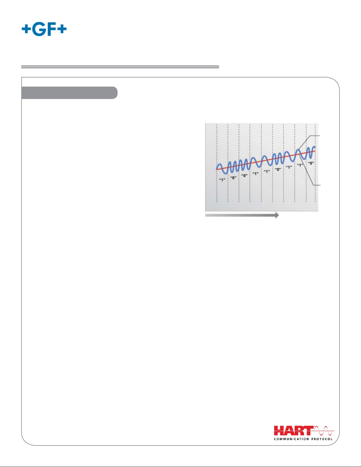
How HART® Works
The HART® (Highway Addressable Remote Transducer)
Protocol uses Frequency Shift Keying (FSK) to superimpose
digital signals on top of the analog 4 to 20 mA current loop.
This allows two-way digital communication to occur and
allows additional information beyond the normal process
data to be communicated to the 9900. This digital signal
can contain data such as device status, diagnostics, etc.
20 mA -
Instruction Sheet
English
Digital
Signal
The HART protocol provides two simultaneous communication
channels: a 4 to 20 mA analog signal and a digital signal.
The analog signal communicates the primary measured
value using the 4 to 20 mA current loop.
Additional information is communicated using a digital
signal superimposed on the 4 to 20 mA signal.
Communication occurs between two HART -enabled devices,
4 mA -
Time
Note: Drawing not to scale
Frequency Shift Keying
Digital over Analog
Time
Analog
Signal
in this application a Signet 9900 Transmitter and a PLC or
handheld device, using standard wiring and termination practices. The HART Protocol communicates at 1200 bits per second without interfering with the 4 to 20 mA signal and allows the PLC or handheld device to communicate two or
more updates per second to and from the 9900.
The HART protocol operates according to the master-slave method. Any communication activity is initiated by the
master, usually a programmable logic controller (PLC) or a data acquisition system. HART accepts two masters: the
primary master - usually the control system (PLC) - and the secondary master - a PC laptop or handheld terminal
used in the fi eld.
HART fi eld devices - the slaves - never send without being requested to do so. They respond only when they have
received a command message from the master. Once a transaction (i.e., a data exchange between the control station and the fi eld device) is complete, the master will pause for a fi xed time period before sending another command,
allowing the other master to break in. The two masters observe a fi xed time frame when taking turns communicating
with the slave devices.
As deployed in the 9900 application, HART allows remote verifying, testing, adjusting and monitoring of primary and
secondary device variables. Features available in the 9900 Transmitter with H COMM Module installed:
• Adjust 4 mA: Allows fi ne-tuning to compensate for errors in other equipment connected to the 9900.
Adjust the minimum and maximum current output.
• Adjust 20 mA: Allows fi ne-tuning to compensate for errors in other equipment connected to the 9900.
Adjust the minimum and maximum current output.
• Supports Multi-Drop Mode: Allows up to four 9900 Transmitters be installed in Multidrop mode.
• Supports all Universal HART Protocol Revision 7.2 commands
• Supports many Common Practice Commands
• Makes Primary and Secondary values available at PLC. Secondary values are sensor-dependent and are
available with pH, Conductivity, Resistivity, Salinity and Level sensors.
HART® is a registered trademark of the HART Communication Foundation, Austin, Texas, USA.
Any use of the term HART hereafter in this document implies the registered trademark.
Page 2
Installation
If the 9900 Base Unit will be mounted in a panel, plug-in modules may
be installed either before or after the base unit is mounted. If the 9900
Base Unit will be mounted using the accessory wall mount bracket,
install plug-in modules fi rst. If the Direct Conductivity/Resistivity
Module will be included in your unit, install the H COMM module fi rst
and then install Conductivity/Resistivity Module over the H COMM
Module.
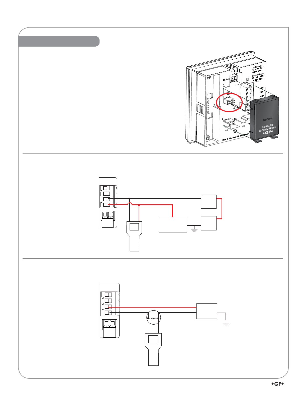
To install the H COMM module, carefully align the module pins into its
plug (see illustration) and push the module straight in until the tabs on
the bottom edge snap into place.
DC Power
Loop Voltage
To uninstall, squeeze tabs, grasp the module and pull straight out.
Be careful not to bend the pins when installing or removing the
module to or from the base unit.
Connecting HART with a Loop-powered sensor
9900 Device
Loop +
Loop –
Connections
Black
Red
Optional ammeter
(recommended for
4 to 20 mA trim only)
Hand-held device
(Secondary HART Master)
(Typical installation)
Connecting HART to a Hand-Held Master Device
(Primary HART Master)
–
PLC
Device
+
+
Power
–
Supply
3-9900.395
H COMM Module
(Typical installation)
2
9900 H COMM Module Instruction Sheet
Loop +
Loop –
9900 Device
Connections
Red
Black
+
250
Load Resistor
Hand-held device
(HART Master)
–
Power
Supply
Page 3
NOTE: From this point forward the term “9900 Transmitter” or “Transmitter” will assume the H COMM Module
is installed unless otherwise noted.
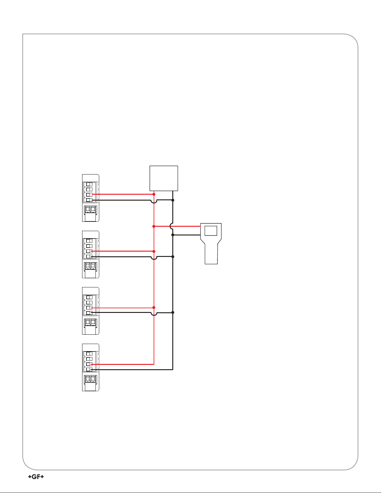
Multi-Drop Mode
Up to four 9900 Transmitters can be connected in Multi-Drop mode using the H COMM Module.
To ensure proper operation in Multi-Drop mode, confi gure each 9900 Transmitter with its own poll address using a
confi guration tool (laptop or hand-held device).
After confi guring the 9900 Transmitter for multi-drop function, reset the Transmitter (remove power for fi ve seconds
then apply power) before use.
Connecting HART in Multi-Drop mode
Device 1
Loop +
Loop –
Device 2
Loop +
Loop –
Device 3
Loop +
Loop –
9900
Connections
Red
Black
Red
Black
Red
Black
(HART Master)
PLC
Device
+
–
(Typical four-unit installation)
Red
Black
Hand-held device
(Secondary HART Master)
Device 4
Loop +
Loop –
Red
Black
39900 H COMM Module Instruction Sheet
Page 4

Operation
Loop Powered systems require a minimum of 24 VDC. If connecting with DC, nominal 12 VDC is acceptable.
(See Power Wiring section in the Signet 9900 Transmitter Operating Instructions manual.)
In LVL/VOL mode, the primary variable will always represent Level, the secondary variable will always represent
Volume. In pH, Conductivity, Resistivity and Salinity systems the secondary variable represents the temperature.
Loop Current Trim Procedure
The Loop Current HART commands allow a Master HART device to update a loop current value in the 9900
Transmitter and to perform a two-point calibration (zero and span) of the loop current.
1. Use Command 40 (Enter/Exit Fixed Current Mode) to update the 4.00 mA current.
2. Using the measured value of your reference instrument (either a digital multimeter or the HART Master device),
set the zero trim using Command 45 (Trim Loop Current Zero). The transmitter will then trim its calibration and
return the loop current value in the response message. The response value may differ slightly from the value sent
by the Master due to rounding.
3. Use Command 40 (Enter/Exit Fixed Current Mode) to update the 20.00 mA current.
4. Using the measured value of your reference instrument (either a digital multimeter or the HART master device),
set the span trim using Command 46 (Trim Loop Current Gain). The transmitter will then trim its calibration and
return the loop current value in the response message. The response value may differ slightly from the value sent
by the Master due to rounding.
5. Repeat steps 1 through 4 as needed to gain the accuracy desired. Once the loop current is calibrated to your
satisfaction, return the device to normal operation by issuing Command 40 (Enter/Exit Fixed Current Mode)
with a value of 0.0. This will take the 9900 out of fi xed current mode.
Note: With the H COMM Module installed, the following functions are not accessible via the 9900 keypad:
• Trim Loop Current
• Test Loop Current
These functions are only accessible via the HART interface.
Changes to Units of Measure in Transmitter
HART devices can be used to change the units of measure in a 9900 Transmitter. After an update, you must cycle
power to the 9900 Transmitter (remove power for 5 seconds, then restore power). In a fl ow system, the units update
automatically and it is not necessary to cycle power to the 9900 Transmitter.
4
9900 H COMM Module Instruction Sheet
Page 5

HART Commands
Universal Commands
All HART Rev. 7.2 Universal Commands are supported:
CMD
ID
0 Read Unique Identifi er
1 Read Primary Variable
2 Read Loop Current And Percent Of Range
3 Read Dynamic Variables And Loop Current
6 Write Polling Address
7 Read Loop Confi guration
8 Read Dynamic Variable Classifi cation
9 Read Device Variable With Status
11 Read Unique Identifi er Associated With T ag
12 Read Message
13 Read Tag, Descriptor, Date
14 Read Primary Variable Transducer Information
15 Read Device Information
16 Read Final Assembly Number
17 Write Message
18 Write Tag, Descriptor, Date
19 Write Final Assembly Number
20 Read Long Tag
21 Read Unique Identifi er Associated With Long Tag
22 Write Long Tag
38 Reset Confi guration Changed Flag
48 Read Additional Device Status
Function
Command 0 – Read Unique Identifi er
Returns device type, device and software revision levels, device
status, and codes for the manufacturer and product information.
Command 1 – Read Primary Variable
Returns the numeric value of the Primary Variable (the 4 to 20
mA current loop) and the unit code for that value (e.g. ’45.3’ and
‘Degrees Celsius’).
Command 2 – Read Loop Current and Percent of Range
Returns the loop current value of the 4 to 20 mA current loop and
the percent of range (e.g. ’12.0’ and ‘50%’).
Command 3 – Read Dynamic Variables and Loop Current
Returns the loop current value of the 4 to 20 mA current loop, as
well as the numeric value of the Secondary Variable (if present)
and the Secondary Value’s unit code.
Command 6 – Write Polling Address
Enables (or disables) Multi-Drop mode. While in Multi-Drop mode,
loop current is held at a fi xed value and is no longer available for
signaling. Also sets the polling address of the device for
Multi-Drop mode.
Command 7 – Read Loop Confi guration
Reads the polling address of the device and the loop confi guration
(see Command 6).
Command 8 – Read Dynamic Variable Classifi cations
Returns the classifi cation code for the Primary Variable and Secondary Variable (if present).
Command 9 – Read Device Variable with Status
Returns the value, status, variable code, variable classifi cation and unit code of up to four device variables.
Command 11 – Read Unique Identifi er Associated with Tag
Returns all identity information associated with the device, i.e., the device type, device revision level and Device ID.
Issued using the ‘tag’.
Command 12 – Read Message
Read back the message stored in the device. See Command 17.
Command 13 – Read Tag, Descriptor, Date
Reads the tag, descriptor and date values contained within the device. See Command 18.
Command 14 – Read Primary Variable Transducer Information
Reads transmitter serial number, unit code, upper and lower limits and minimum span for primary variable.
Command 15 – Read Device Information
Returns the alarm selection code, transfer function code, upper and lower range values, write protect code and
unit code.
59900 H COMM Module Instruction Sheet
Page 6

Universal Commands - Cont.
Command 16 – Read Final Assembly Number
Returns the assembly number of the device. This will be defi ned by the customer. See Command 19.
Command 17 – Write Message
Write a message to be stored in the device. See Command 12.
Command 18 – Write Tag, Descriptor, Date
Writes the tag, descriptor and date values into the device. See Command 13.
Command 19 – Write Final Assembly Number
Writes the fi nal assembly number of the device. See Command 16.
Command 20 – Read Long Tag
Read the 32-byte long tag. The ‘long tag’ is separate from the ‘tag’ that is used in Commands 13 & 18.
Command 21 – Read Unique Identifi er Associated with Long Tag
Returns all identity information associated with the device - the device type, device revision level and Device ID.
Issued using the long tag.
Command 22 – Write Long Tag
Write the 32-byte long tag. See Command 20.
Command 38 – Reset Confi guration Changed Flag
Resetting the device’s confi guration changes counter back to 0.
Command 48 – Read Additional Device Status
Returns extended device status information.
Supported HART Common Practice Commands
The following Common Practice Commands are supported.
CMD
ID
40 Enter/Exit Fixed Current Mode
45 Trim Loop Current Zero
46 Trim Loop Current Gain
54 Read Device Variable Information
Function
Command 40 - Enter/Exit Fixed Current Mode
The loop current of the 9900 is set to the value transmitted in the command (in
milliamperes). Setting a level of ‘0’ exits Fixed Current Mode. If the device is in
Multi-Drop mode, Error Code 11 will be returned.
Command 45 – Trim Loop Current Zero
The 9900 will trim its offset of the loop current to match the loop current value
sent to it. This is typically performed at 4.00 milliamperes to optimize calibration.
Command 46 – Trim Loop Current Gain
The 9900 will trim the gain of the loop current to match the loop current value sent to it. This is typically performed at
20.00 milliamperes to optimize calibration.
Command 54 – Read Device Variable Information
Returns serial number, limits, damping value and minimum span for a selected device variable.
6
9900 H COMM Module Instruction Sheet
Page 7

Unit Codes
The H COMM module uses standard HART Foundation Protocol 7.2 unit codes. The unit code allows the HART
Master to interpret and display the units of measure (e.g., GPM, PPB, °F, etc.) with two exceptions.
The following Unit Codes will not be interpreted by the HART Master:
Code Measurement Unit
240 Cubic Centimeters
244 Parts per Thousand
A HAR T Master will display these unit codes instead of the units of measure that the
code represents.
79900 H COMM Module Instruction Sheet
Page 8

Ordering Information
Mfr. Part No. Code Description
3-9900.395 159 001 697 H COMM Module
Georg Fischer Signet LLC, 3401 Aero Jet Avenue, El Monte, CA 91731-2882 U.S.A. • Tel. (626) 571-2770 • Fax (626) 573-2057
For Worldwide Sales and Service, visit our website: www.gfsignet.com • Or call (in the U.S.): (800) 854-4090
For the most up-to-date information, please refer to our website at www.gfsignet.com
3-9900.094 Rev. C 03/13 English © Georg Fischer Signet LLC 2013
 Loading...