

Page 1
Signet 8450-3 Pressure Transmitter
Output -
Output +
System Pwr
Loop System Pwr
Loop +
2
1
4
3
Sensr Gnd
(SHIELD)
Sensr IN
(RED)
Sensr V+
(BLACK)
7
6
5
8052
92 mm
(3.6 in.)
97 mm
(3.8 in.)
56 mm
(2.2 in.)
41 mm
(1.6 in.
)
Optional
Rear
Cover
SIDE VIEW
Field Mount
96 mm
(3.8 in.)
96 mm
(3.8 in.)
96 mm
(3.8 in.)
quick-clips
gasket
panel
terminals
mounting
bracket
latch
Panel Mount
SIDE VIEW
FRONT VIEW
Field Mount &
Panel Mount
Panel Mount
Installation Detail
107 mm (4.2 in.)
42 mm
(1.7 in.)
65 mm
(2.5 in.)
*3-8450.090-3*
3-8450.090-3 Rev. J 01/13 English
English
CAUTION!
• Remove power to unit before wiring
input and output connections.
• Follow instructions carefully to avoid
personal injury.
Contents
1. Installation
2. Specifi cations
3. Electrical Connections
4. Menu Functions
Pres1: 4.5 psi
Pres2: 2.3 psi
Signet Pressure
Transmitter
ENTER
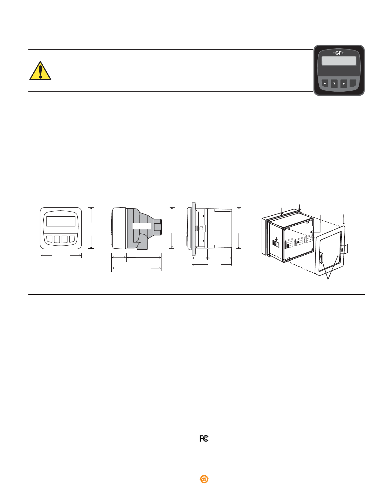
1. Installation
ProcessPro transmitters are available in two styles: panel mount and fi eld mount. The panel mount is supplied with the necessary
hardware to install the transmitter. This manual includes complete panel mounting instructions.
Field mounting requires one of two separate mounting kits. The 3-8052 integral kit joins the sensor and instrument together into a
single package. The 3-8050 Universal kit enables the transmitter to be installed virtually anywhere.
Detailed instructions for integral mounting or other fi eld installation options are included with the 3-8052 Integral kit or the 3-8050
Universal kit.
1.1 Panel Installation
1. The panel mount transmitter is designed for installation using a ¼ DIN Punch. For manual panel cutout, an adhesive template is
provided as an installation guide. Recommended clearance on all sides between instruments is 1 inch.
2. Place gasket on instrument, and install in panel.
3. Slide mounting bracket over back of instrument until quick-clips snap into latches on side of instrument.
4. To remove, secure instrument temporarily with tape from front or grip from rear of instrument. DO NOT RELEASE.
Press quick-clips outward and remove.
2. Specifi cations
General
Compatibility: Signet 2450 Pressure Sensor
Accuracy: ±1% of full scale
Enclosure:
• Case: PBT
• Panel case gasket: Neoprene
• Window: Polyurethane coated polycarbonate
• Keypad: Sealed 4-key silicone rubber
• Weight: Approx. 325 g (12 oz.)
Display:
• Alphanumeric 2 x 16 LCD
• Update rate: 1 second
• Contrast: User selected, 5 levels
Electrical
Power: 12 to 24 VDC ±10%, regulated,
Sensor Input:
• Range: 0-250 psig, 0-17 bar, 0-1700 kPa
Current output:
• 4 to 20 mA, isolated, fully adjustable and reversible
• Max loop impedance: 50 Ω max. @ 12 V,
325 Ω max. @ 18 V,
600 Ω max. @ 24 V
• Update rate: 100 ms
• Accuracy: ±0.03 mA
60 mA max current
Open-collector output: Hi, Lo, Off, Programmable:
• Optically isolated, 50 mA max. sink, 30 VDC max. pull-up
voltage
• Hysteresis: User adjustable
Environmental
• Operating temperature: -10 °C to 70 °C (14 °F to 158 °F)
• Storage temperature: -15 °C to 80 °C (5 °F to 176 °F)
• Relative humidity: 0 to 95%, non-condensing
• Maximum altitude: 2000 m (6562 ft)
• Insulation category: II
• Rating: NEMA 4X/IP65 front
Standards and Approvals
• CE, UL listed
• Immunity: EN50082-2
• Emissions: EN55011 Class B
• Manufactured under ISO 9001 for Quality, ISO 14001
for Environmental Management and OHSAS 18001 for
Occupational Health and Safety.
Declaration of Conformity according to FCC Part 15
This device complies with Part 15 of the FCC rules.
Operation is subject to the following two conditions:
(1) This device may not cause harmful interference, and,
(2) This device must accept any interference received,
including interference that may cause undesired operation.
China RoHS (Go to www.gfsignet.com for details)
Page 2
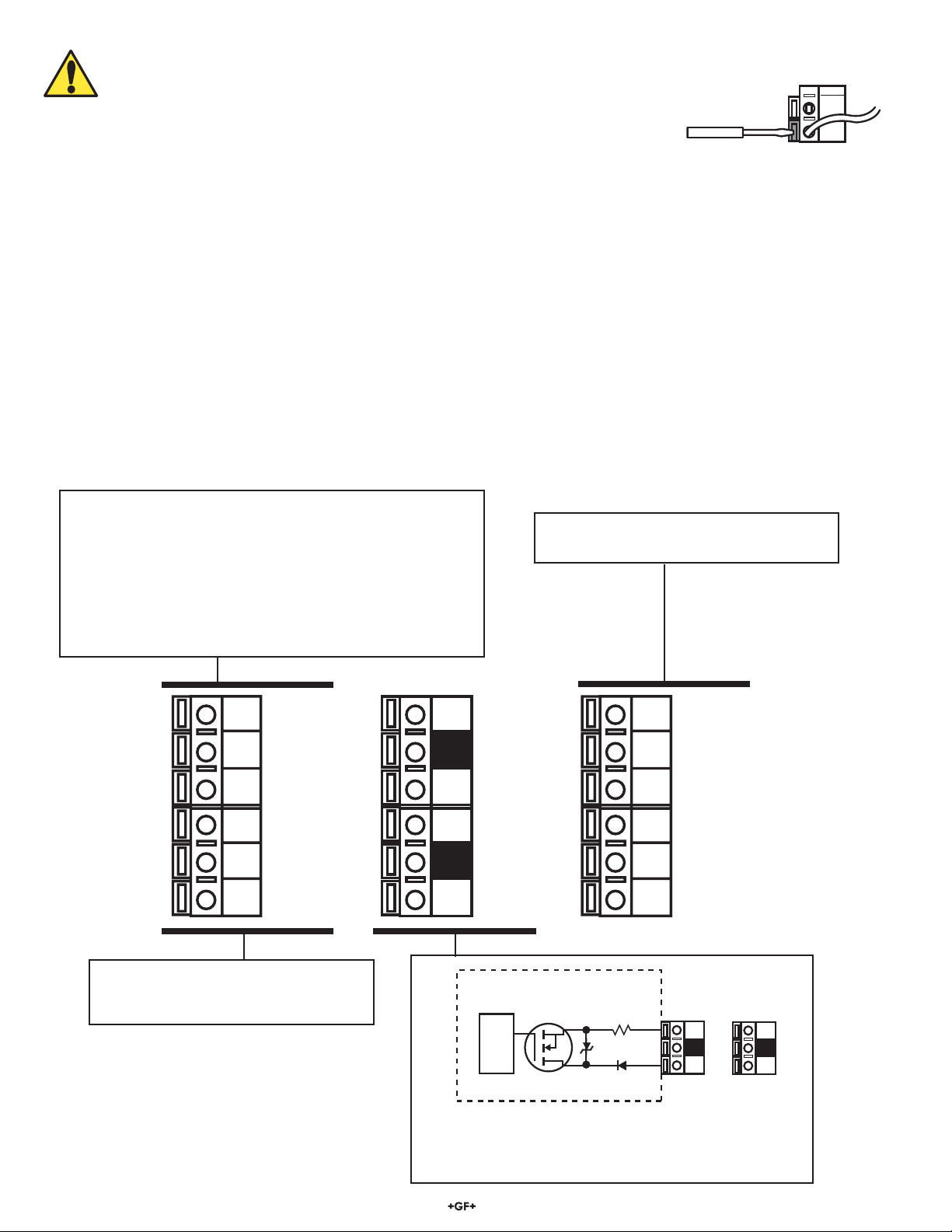
3. Electrical Connections
10
9
8
7
6
5
4
3
2
1
16
15
14
13
12
11
Output 2-
Output 2+
Output 1-
Output 1+
Loop 2-
Loop 2+
System Pwr
Loop -
System Pwr
Loop +
AUX
Power -
AUX
Power +
Snsr 2 Gnd
(WHITE)
Snsr 2 IN
(RED)
Snsr 2 V+
(BLACK)
Snsr 1 Gnd
(WHITE)
Snsr 1 IN
(RED)
Snsr 1 V+
(BLACK)
1
15
S
D
2
_
+
Internal open-collector
output circuit
Outputs
Isolation
Caution: Failure to fully open terminal jaws before removing wire may permanently damage instrument.
Wiring Procedure
1. Remove 13 mm - 16 mm (0.5 in. - 0.625 in.) of insulation from wire end.
2. Press the orange terminal lever downward with a small screwdriver to open terminal jaws.
3. Insert exposed (non-insulated) wire end in terminal hole until it bottoms out.
4. Release orange terminal lever to secure wire in place. Gently pull on each wire to ensure a good connection.
Wiring Removal Procedure
1. Press the orange terminal lever downward with a small screwdriver to open terminal jaws.
2. When fully open, remove wire from terminal.
Wiring Tips:
• Do not route sensor cable in conduit containing AC power wiring. Electrical noise may interfere with sensor signal.
• Routing sensor cable in grounded metal conduit will help prevent electrical noise and mechanical damage.
• Seal cable entry points to prevent moisture damage.
• Only one wire should be inserted into a terminal. Splice double wires outside the terminal.
• If your system uses a single sensor, it must be located within 122 m (400 ft.) of the transmitter.
• If your system uses two sensors, the total length of cable connected to the transmitter is limited to 122 m (400 ft.)
• The 3 conductors from a dual-sensor system can be tied together and then a single set of wires continued on to the transmitter.
• For best performance, ground the sensor SHIELD wire to a local earth ground at a point near the sensor.
(Experiment with connecting the sensor shield wire to different local ground points to identify best signal quality.)
Terminals 3-4: Primary Loop Power
12-24 VDC ±10% system power and current loop connections.
SINGLE SENSOR system MUST use terminals 3-4.
Terminals 5-6: 12-24 VDC ± 10%
Power and current loop connections for second sensor.
• Maximum loop impedance:
50Ω max. at 12 V
325Ω max. at 18 V
600Ω max. at 24V
Terminals 11-16: Dual digital sensor inputs
See next page for more information.
2
1
Terminals 1-2: Auxiliary power is used
only if two sensors are connected to the
transmitter.
2 Signet 8450-3 Pressure Transmitter
Terminals 7-10: Open-Collector Outputs
• Two transistor outputs programmable as High or
Low alarm with adjustable hysteresis
• Outputs can be disabled (Off) if not used
Page 3
16
15
14
13
12
11
Signet 2450
Pressure Sensors
Terminals
White (Snsr 2 Gnd)
Red (Snsr 2 IN)
Black (Snsr 2 V+)
White (Snsr 1 Gnd)
Red (Snsr 1 IN)
Black (Snsr 1 V+)
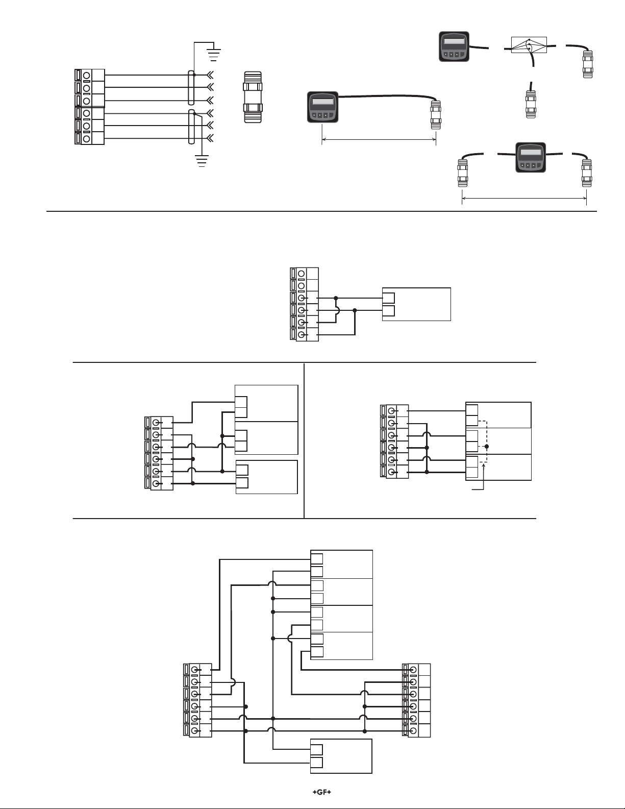
3.1 Sensor Input Connections
+
+
-
+
-
+
+
+
-
+
+
+
+
+
-
+
6
5
4
3
2
1
6
5
4
3
2
1
6
5
4
3
2
1
6
5
4
3
2
1
6
5
4
3
2
1
*
Example: Two transmitters connected to PLC/Recorder with separate power supply
Loop 2 Loop 2 +
System Power Loop 1 System Power Loop 1 +
AUX Power AUX Power +
Loop 2 -
Loop 2 +
System Power Loop 1 -
System Power Loop 1 +
AUX Power -
AUX Power +
PLC or Recorder
Channel 3
4-20 mA in
Channel 4
4-20 mA in
Transmitter 1
Terminals
Transmitter 2
Terminals
Channel 1
4-20 mA in
Channel 2
4-20 mA in
Power
Supply
12-24 VDC
* *
*
* *
*
*
*
Stand-alone application, no current loop used
Transmitter
Terminals
Power
Supply
12-24 VDC
Connection to a PLC with built-in power supply
Internal
PLC
Connection
PLC or Recorder
Loop 2 -
Loop 2 +
System Power Loop 1 -
System Power Loop 1 +
AUX Power -
AUX Power +
Transmitter
Terminals
Loop 2 -
Loop 2 +
System Power Loop 1 -
System Power Loop 1 +
AUX Power -
AUX Power +
Transmitter
Terminals
Loop 2 -
Loop 2 +
System Power Loop 1 -
System Power Loop 1 +
AUX Power -
AUX Power +
Power
Supply
12-24 VDC
PLC Terminals
Channel 1
4-20 mA
Power
Supply
12-24 VDC
Channel 2
4-20 mA
Channel 2
4-20 mA
Channel 1
4-20 mA
NC
NC
AUX power required only where two sensors are used
AUX power required only where two sensors are used
AUX power required only where two sensors are used
AUX power required only where two sensors are used
A
B
A
B
C
Signet Pressure
Transmitter
Pressure Cal:
0.0 psi >
ENTER
Signet Pressure
Transmitter
Pressure Cal:
0.0 psi >
ENTER
Transmitter
A + B 122 m (400 ft.)
J-box
Transmitter
A + B + C 122 m (400 ft.)
Signet Pressure
Transmitter
Pressure Cal:
0.0 psi >
ENTER
Transmitter
122 m (400 ft.)
3.2 System Power/Loop Connections
3Signet 8450-3 Pressure Transmitter
Page 4

Pres1: 4.5 psi
Pres2: 2.3 psi
ENTER
Signet Pressure
Transmitter
3.3 Open Collector Output
Hysteresis
Time
Low Setpoint
Process
Output energized
Output de-energized
Hysteresis
Time
High Setpoint
Process
The Open Collector output can be used as a switch that responds
when the process variable moves above or below a setpoint.
• Low:
Output triggers when process variable is less than the setpoint.
The output will relax when the process variable moves above the
setpoint plus the hysteresis value.
• High:
Output triggers when process variable is greater than the
setpoint. The output will relax when the process variable moves
below the setpoint plus the hysteresis value.
Delta Pressure (Differential Mode)
If two sensors are connected to the transmitter, the DELTA
(Sensor 1 - Sensor 2) can be assigned to output. To enable
differential mode, the selected output's "Source" selection must
be set to "DP".
For pressure and temperature transmitters ensure Sensor 1 is
equal to ID 1:
Sensor 1 - Sensor 2
Difference = 60
Example: 4-20 mA
Sensor 1 (80)
Sensor 2 (20)
ENTER
Loop1 Source: DP
Loop1 Range: 0-120
Loop1: = 12.00 mA
Example: Output
Output1 Source: DP
Output1 Mode: Low
Output1 Setpoint: 70
Output1 = ON
VIEW menu
• During normal operation, the ProcessPro displays the VIEW menu.
• When using the CALIBRATE or OPTIONS menus, the ProcessPro will return to the VIEW menu if no
activity occurs for 10 minutes.
• To select the item you want displayed, press the UP or DOWN arrow keys. The items will scroll in a
continuous loop.
• Changing the display selection does not interrupt system operations.
• No keycode is necessary to change display selection.
• Output settings cannot be edited from the VIEW menu.
View Menu
4 Signet 8450-3 Pressure Transmitter
Display Description
Press1: 7.89 psi
Press2: 4.56 psi
Delta Pressure:
3.33 psi
Monitor Pressure 1 and Pressure 2 simultaneously.
This is the permanent view display.
Monitor the delta pressure (Channel 1 rate - channel 2 rate = Delta Pressure)
This is a permanent display.
The displays below are temporary. After 10 minutes the display returns to the permanent display.
Loop 1 Output:
12.00 mA
Loop 2 Output:
Monitor the 4 to 20 mA output for Loop 1 and 2.
7.65 mA
Last CAL:
02-10-09
Monitor date for scheduled maintenance or date of last calibration.
(See description in Calibrate Menu.)
Page 5

Output1 Setpnt:
1
0.00 psi
Output1 Setpnt:
0
0.00 psi
ENTER
Output1 Setpnt:
0
0.00 psi
Output Setpnt:
09.00 psi
Output1 Setpnt:
Saving
Output1 Setpnt:
09.00 psi >
ProcessPro Editing Procedure:
CALIBRATE: ----
Enter Key Code
CALIBRATE: *---
Enter Key Code
CALIBRATE: **--
Enter Key Code
CALIBRATE: ***-
Enter Key Code
>
Switch ID:
>
Switch ID:
10.00 psi >
Output1 Setpnt:
Step 1. Press and hold ENTER key:
• 2 seconds to select the CALIBRATE menu
• 5 seconds to select the OPTIONS menu.
Step 2. The Key Code is UP-UP-UP-DOWN keys in sequence.
• After entering the Key Code, the display will show the fi rst item in the selected menu.
Step 3. Scroll menu with UP or DOWN arrow keys.
Step 4. Press RIGHT ARROW key to select menu item to be edited.
• The fi rst display element will begin fl ashing.
Step 5. Press UP or DOWN keys to edit the fl ashing element.
• RIGHT ARROW key advances the fl ashing element.
Step 6. Press ENTER key to save the new setting and return to Step 3.
Notes on Step 1:
• The View Menu is normally displayed.
• The CALIBRATE and OPTIONS menus require a KEY CODE.
Press &
hold for
access:
VIEW
ENTER
Notes on Step 2:
If no key is pressed for 5 minutes while display is showing "Enter
Key Code", the display will return to the VIEW menu.
2s 5s
CALIBRATE
OPTIONS
Notes on Steps 3 and 4:
• Refer to pages 6 and 7 for complete listing of menu items and their use.
• From the Step 3 display, pressing the UP and DOWN keys simultaneously will
return the display to the VIEW menu.
• If no key is pressed for 10 minutes, display will also return to the VIEW menu.
Step 3: Finished Editing?
Press the UP and DOWN keys simultaneously after
saving the last setting to return to normal operation.
First item in
CALIBRATE menu
Step 3
Step 4
Notes on Steps 5 and 6:
• All output functions remain active during editing.
• Only the fl ashing element can be edited.
• RIGHT ARROW key advances the fl ashing element in a continuous loop.
• Edited value is effective immediately after pressing ENTER key.
• If no key is pressed for 10 minutes unit will restore the last saved value and return to step 3.
• Step 6 (pressing ENTER key) always returns you to Step 3.
• Repeat steps 3-6 until all editing is completed.
Step 5: Made an Error?
Press the UP and DOWN keys simultaneously
while any element is fl ashing. This will recall the
last saved value of the item being edited and
return you to Step 3.
Step 5
Step 6
5Signet 8450-3 Pressure Transmitter
Page 6
Calibrate Menu
Display
(Factory settings shown)
Switch ID
PSI
Pressure Units:
psi >
Set:
Pressure1
Set:
Pressure2
Loop 1 Source
Pressure1
Loop 1 Range: psi
0.0 → 100.0 >
Output 1 Source
Pressure1
Description
Reverses the identifi cation of Sensor inputs: Pressure 1 becomes identifi ed as Pressure 2,
Pressure 2 becomes identifi ed as Pressure1.
Use this function to make corrections if the sensors are in the wrong order for a DELTA
PRESSURE measurement.
Select Pressure units for both input channels: psi, bar or kPa.
Provides a maximum 5 psi offset to match 8450 to external reference.
Enter “-999” to restore the original Factory calibration value.
Changes to this setting will become effective when the display exits the Calibrate menu.
Select the INPUT SIGNAL represented by this 4-20 mA output:
Pressure 1, Pressure 2, or Delta Pressure (Pressure1 - Pressure2.)
Check the 2450 Sensor instructions for the range capability of your sensor.
Be sure to modify this setting if you change the Pressure Units.
Select the INPUT SIGNAL represented by this Open Collector Output:
Pressure 1, Pressure 2, or the Delta Pressure (Pressure1 - Pressure2.)
Output1 Mode:
Low >
Output1 Setpnt:
10.0 psi >
Output1 Hys:
5 >
Last CAL:
2-10-09
Select the desired mode of operation for the Open Collector output. Options available are
High or Low. The signal may be disabled (Off) if not used.
In Low or High Mode, the Open Collector output #1 will be activated when the pressure
reaches this value. Be sure to modify this setting if you change the Pressure Units.
The Open Collector output will be de-energized at Setpoint ± Hysteresis, depending on High
or Low Setpoint selection.
Use this “note pad” to record important dates, such as annual recertifi cation or scheduled
maintenance.
Menu items will repeat for Loop 2 and Output 2.
6 Signet 8450-3 Pressure Transmitter
Page 7

Options Menu
Display
(Factory settings shown)
Description
Contrast:
3 >
Decimal
*****. >
Averaging
Off >
Adjust the LCD contrast for best viewing. A setting of 1 is lowest contrast, 5 is highest. Select
lower contrast if the display is in warmer ambient surroundings.
Set the decimal to the best resolution for your application. The display will automatically scale
up to this resolution. Select *****., ****.*, ***.**, **.*** or *.****
OFF provides the quickest output response to changes in fl ow. Longer averaging period
produces more stable display and output response. Select LOW, HIGH or OFF.
Output1 Active
Low >
Output2 Active
Active HIGH: This setting is used to turn a device (pump, valve) ON at the setpoint.
Active LOW: This setting is used to turn a device OFF at the setpoint.
Low >
Loop1 Adjust
4.00 mA >
Loop1 Adjust
20.00 mA >
Adjust the minimum and maximum current output. Use this setting to match the system output
to any external device. The display value represents the precise current output.
Adjustment limits:
• 3.80 mA < 4.00 mA > 5.00 mA
• 19.00 mA < 20.00 mA > 21.00 mA
Test Loop 1:
>
Test Loop 2:
Press UP or DOWN keys to manually order any output current value from 3.6 mA to
21.00 mA to test current loop output.
>
Test Output 1:
>
Test Output 2:
Press UP or DOWN keys to manually toggle the state of open collector output.
>
Menu items will repeat for Loop 2 and Output 2.
7Signet 8450-3 Pressure Transmitter
Page 8

Troubleshooting
Display Condition Possible Causes Suggested Solutions
Check Sensor?
Too much error
CHECK SENSOR
Reset to Factory
Calibration
Relay is always activated
SETUP READ ERROR
Press Any Key
• Sensor not wired properly.
• Sensor connected to 8450 while
power is on.
• Defective sensor.
The value entered in Set Pressure fi eld is
greater than 5 psi deviation from sensor
input. (The 8450 allows a maximum of
5 psi calibration offset.).
Value in SET PRESSURE fi eld is -999.
• Hysteresis value too large
• Defective transmitter
Memory fault occurred.
• Correct sensor wiring.
• Recycle power with all sensors connected.
• Replace defective sensor.
• Confi rm calibration values.
• Remove sensor from installation, check
8450 reading (should be zero). If necessary,
Set Pressure to zero, reinstall sensor, then
recalibrate.
Entering "-999" in this fi eld will remove all user
calibration input and restore the factory values.
• Change the hysteresis value
• Replace transmitter
• Press any key to reload factory presets.
• Reprogram all setpoints.
• If this message appears again, replace the
8450.
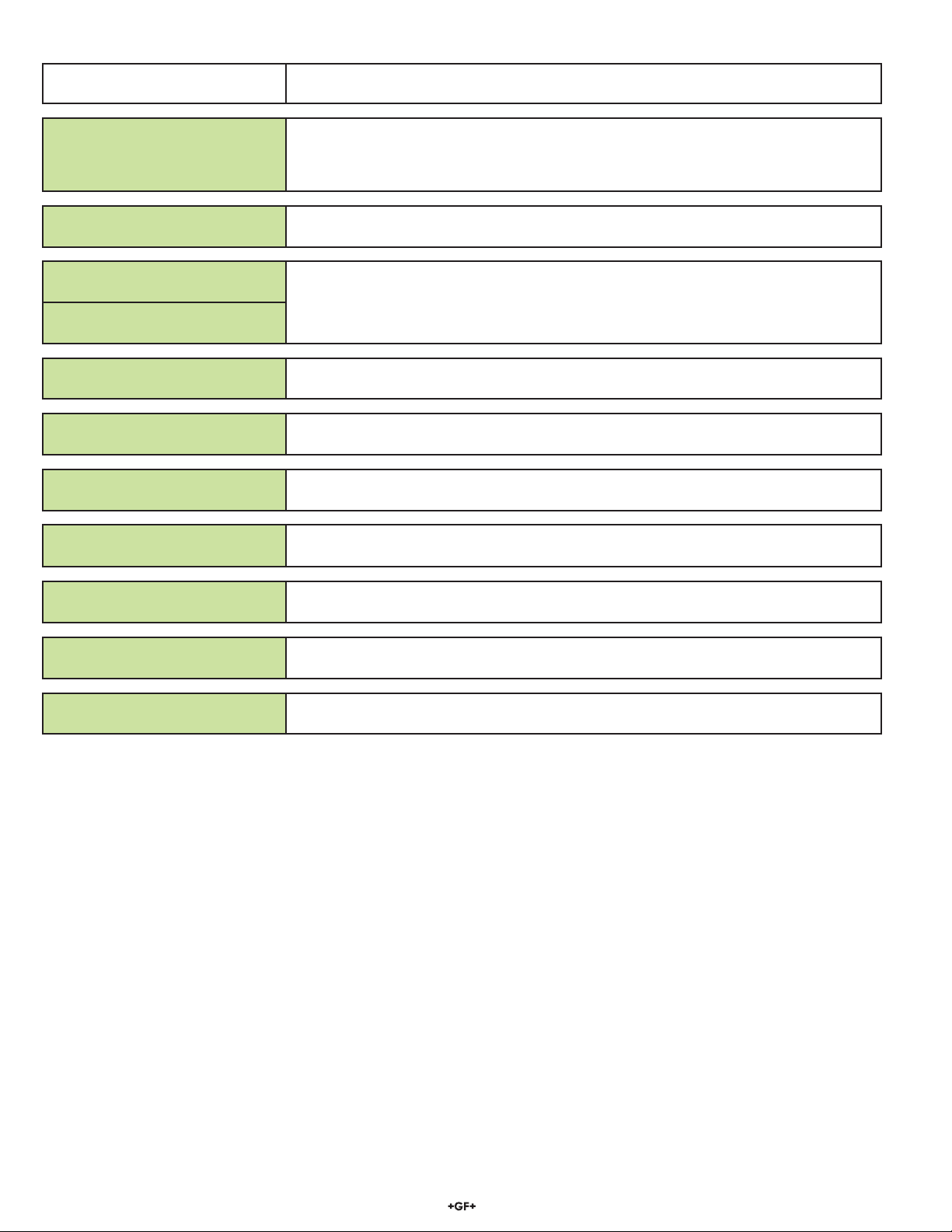
Ordering Information
Mfr. Part No. Code Description
3-8450-1 159 000 041 Pressure transmitter, Field mount
3-8450-1P 159 000 042 Pressure transmitter, Panel mount
3-8450-2 159 000 043 Pressure transmitter, Field mount with relays
3-8450-2P 159 000 044 Pressure transmitter, Panel mount with relays
3-8450-3 159 000 045 Pressure transmitter, Field mount with dual input/output
3-8450-3P 159 000 046 Pressure transmitter, Panel mount with dual input/output
Accessories
Mfr. Part No. Code Description
3-8050 159 000 184 Universal mounting kit
3-8052 159 000 188 3/4 in. Integral mounting kit
3-8052-1 159 000 755 3/4 in. NPT mount junction box
3-8050.395 159 000 186 Splashproof rear cover
3-8050.396 159 000 617 RC Filter kit (for relay use)
3-0000.596 159 000 641 Heavy duty wall mount bracket
3-5000.598 198 840 225 Surface Mount Bracket
3-9000.392 159 000 368 Liquid tight connector kit for rear cover (includes 3 connectors)
3-9000.392-1 159 000 839 Liquid tight connector kit, NPT (1 piece)
3-9000.392-2 159 000 841 Liquid tight connector kit, PG13.5 (1 piece)
Georg Fischer Signet LLC, 3401 Aero Jet Avenue, El Monte, CA 91731-2882 U.S.A. • Tel. (626) 571-2770 • Fax (626) 573-2057
For Worldwide Sales and Service, visit our website: www.gfsignet.com • or call (in the U.S.): (800) 854-4090
For the most up-to-date information, please refer to our website at www.gfsignet.com
3-8450.090-3 Rev. J 01/13 English © George Fischer Signet, Inc. 2013
 Loading...