

Page 1
Signet 8059 External Relay Module
100 - 240 V
50/60 Hz, 20 VA
NC C NO
RELAY A
NC C NO
RELAY B
NC C NO
RELAY C
NC C NO
RELAY D
+
S3L
-
+
S3L
-
OUTPUT 24VDC
+ -
AC INPUT
INPUT
PASS-THRU
L N
COM
32:(5
Signet 3-8059 Relay Module
Test A
Test B
Test C
Test D
Relay A
Relay B
Relay C
Relay D
LISTED
E171559
®
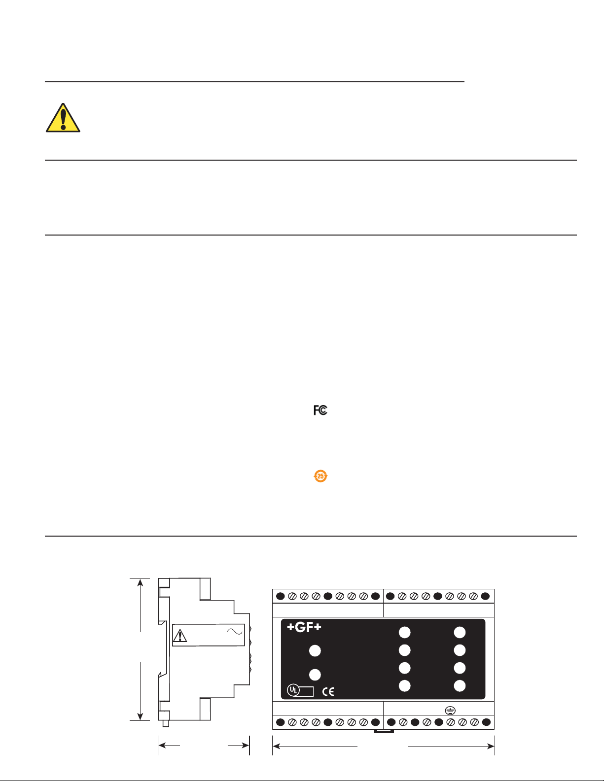
89 mm
(3.5 in.)
57 mm
(2.25 in.)
108 mm
(4.25 in.)
English
*3-8059.090*
3-8059.090 Rev. G 03/13 English
WARNING!
• Remove power to unit before wiring input and output connections.
• Do not alter product construction.
• This product should only be used for the purposes
and in the manner described in this manual.
• This unit must be installed on a DIN rail.
1. Description
Signet 8059 External Relay Modules supplement the output capabilities of certain host instruments such as Signet 8250 Level
Transmitters. AC-powered versions accept universal line voltage, and also provide 24 VDC output that can be used to power the host
instrument or other device(s). The host instrument controls relay operation by way of a single S3L connection. The compact plastic
housing is DIN rail mountable and includes LED annunciators for each relay, plus one each for power-on and data transfer or test
mode.
Table of Contents
1. Description
2. Specifi cations
3. Installation
4. Power
5. Wiring
6. Operation
7. Relay Test
8. Ordering Information
2. Specifi cations
3
Input: S
via host instrument
Enclosure
Material: Noryl
Type: DIN rail mountable
Electrical connection: Standard screw-type terminals
Shipping weight: 0.37 kg (0.8 lb.)
Power
8059-4AC: 100-240 VAC ± 10%, 50/60 Hz, 20VA
8059-4: 12 to 24 VDC, 100 mA
Add current requirements for external
equipment if using DC output
DC output
8059-4AC: 24 VDC regulated, 300 mA max
8059-4: Pass-through (Input DC less 0.7 VDC)
(12 VDC in = 11.3 VDC out)
Isolation: >5000 Vrms
Relays
Type: SPDT 250VAC/30VDC @ 5A
Resolution: 2 ms
Response time: < 100 ms
Annunciators: Red LED, 1 per relay
Maximum cable: 400 ft. total S
Noryl® is a registered trademark of GE Plastics
L (Signet Sensor Serial Link)
®
UL 94 V-O
3
L wiring
Environmental
Ambient temperature
• Storage: -20 °C to 85 °C (-4 °F to 185 °F)
• Operating: -10 °C to 55 °C (-14 °F to 130 °F)
Relative humidity: 0 to 90% (non-condensing)
Maximum altitude: 2000 m (6500 ft)
Insulation category: II
Pollution degree: 2
Standards and approvals
• CE, UL, CUL
• RoHS Compliant
• Manufactured under ISO 9001 for Quality,
ISO 14001 for Environmental Management and
OHSAS 18001 for Occupational Health and Safety.
Declaration of Conformity according to FCC Part 15
This device complies with Part 15 of the FCC rules.
Operation is subject to the following two conditions:
(1) This device may not cause harmful interference, and,
(2) This device must accept any interference received,
including interference that may cause undesired operation.
China RoHS (Go to www.gfsignet.com for details)
Dimensions
3-8059-4AC version is shown. External dimensions are identical for all versions.
Page 2
DC OUTPUT
+ -
DC INPUT
- +
DC Power terminals
12 to 24 VDC
100 mA maximum
Pass-through DC
(less 0.7 VDC)
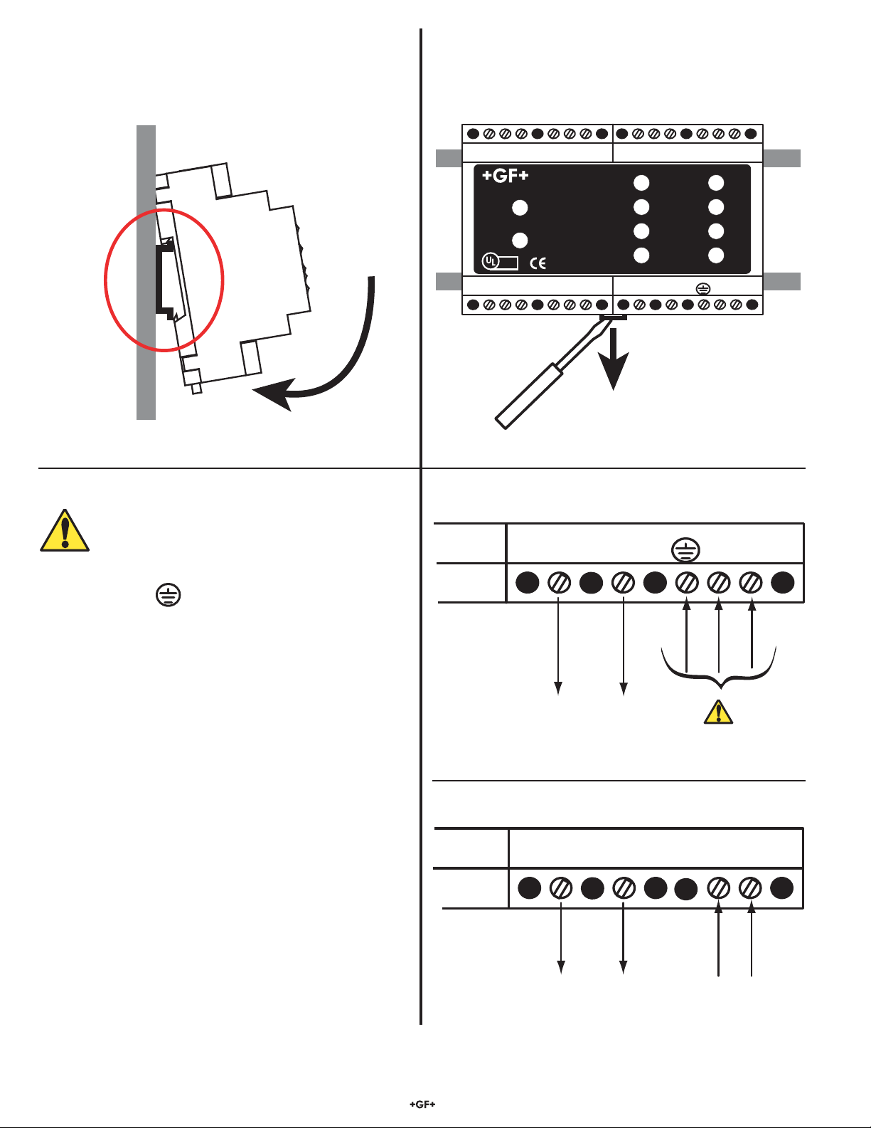
3. Installation
NC C NO
RELAY A
NC C NO
RELAY B
NC C NO
RELAY C
NC C NO
RELAY D
+
S3L
-
+
S3L
-
OUTPUT 24VDC
+ -
AC INPUT
INPUT
PASS-THRU
L N
COM
32:(5
Signet 3-8059 Relay Module
Tes t A
Tes t B
Tes t C
Tes t D
Relay A
Relay B
Relay C
Relay D
LISTED
E171559
®
Removal
Tilt top of the 8059 to insert under top DIN rail, then press bottom
of 8059 until the locking pin snaps onto lower DIN rail.
Insert screwdriver into release mechanism on bottom of 8059.
Pull down on release while lifting 8059 away from the DIN rail.
4. Power
WARNING
• This unit must be installed inside a protected panel.
• Always connect to earth ground.
• Disconnect power before wiring.
• Do not install where persons may inadvertently come in
physical contact with the terminals.
• Include protection devices in the power system in case of
power supply malfunction. A very high voltage may occur at
output terminals during failure.
• Do not touch immediately after removing power. Some
surface areas may be very hot.
• Do not exceed temperature specifi cations.
• Do not store or operate the AC power supply in any
environment subjected to vibrations or shock.
AC Power terminals
OUTPUT 24VDC
+ -
24 VDC Regulated,
300 mA maximum
AC INPUT
N L
100 - 240 VAC
50/60 Hz, 20 VA
Signet 8059 External relay module 2
Page 3

5. Wiring
A + B + C 122 m (400 ft.)
B
A
C*
B
A
C
NC C NO
RELAY A
NC C NO
RELAY B
NC C NO
RELAY C
NC C NO
RELAY D
+
S3L
-
+
S3L
-
OUTPUT 24VDC
+ -
AC INPUT
INPUT
PASS-THRU
L N
COM
32:(5
Signet 3-8059 Relay Module
Test A
Test B
Test C
Test D
Relay A
Relay B
Relay C
Relay D
LISTED
E171559
®
NC C NO
RELAY A
NC C NO
RELAY B
NC C NO
RELAY C
NC C NO
RELAY D
+
S3L
-
+
S3L
-
OUTPUT 24VDC
+ -
AC INPUT
INPUT
PASS-THRU
L N
COM
32:(5
Signet 3-8059 Relay Module
Test A
Test B
Test C
Test D
Relay A
Relay B
Relay C
Relay D
LISTED
E171559
®
S3L
I/O
Terminals
S
3
L Sensor #1
S
3
L Sensor #2
S
3
L
I/O
Terminals
S
3
L Sensor #1
S
3
L Sensor #2
A + B 122 m (400 ft.)
B*
A
B
A
NC C NO
RELAY A
NC C NO
RELAY B
NC C NO
RELAY C
NC C NO
RELAY D
+
S3L
-
+
S3L
-
OUTPUT 24VDC
+ -
AC INPUT
INPUT
PASS-THRU
L N
COM
32:(5
Signet 3-8059 Relay Module
Test A
Test B
Test C
Test D
Relay A
Relay B
Relay C
Relay D
LISTED
E171559
®
NC C NO
RELAY A
NC C NO
RELAY B
NC C NO
RELAY C
NC C NO
RELAY D
+
S3L
-
+
S3L
-
OUTPUT 24VDC
+ -
AC INPUT
INPUT
PASS-THRU
L N
COM
32:(5
Signet 3-8059 Relay Module
Test A
Test B
Test C
Test D
Relay A
Relay B
Relay C
Relay D
LISTED
E171559
®
S3L Sensor
S
3
L Sensor
S
3
L
I/O
Terminals
S3L
I/O
Terminals
+
S3L
- +
S3L
-
INPUT PASS-THRU
8059 I/O terminals
Sensor Gnd
Sensor IN
Sensor V+
Sensor Gnd
Sensor IN
Sensor V+
Black (Sensor V+)
Red (Sensor IN)
Silver (Sensor Gnd)
S3L Sensor #1 S3L Sensor #2
S
3
L
I/O
Terminals
• S3L devices may be connected to any available set of I/O terminals, or may be spliced into existing S3L device cable.
*Sensor may be connected to host instrument via pass-through S
• Only one wire should be inserted into a terminal. Splice double wires outside the terminal.
• The TOTAL cable length from all S
3
L devices to the transmitter must not exceed 122 m (400 ft.).
3
L terminals on the 8059.
• Do not route I/O cables in conduit containing AC power wiring. Electrical noise may interfere with data signal.
• Routing cable in grounded metal conduit will help prevent electrical noise and mechanical damage.
• The sensor confi guration must be reset before the host instrument will recognize a new S
3
L device.
(see Calibrate menu, “Reset Sensor Confi guration” in the 8250 Level Transmitter manual.)
Dual Sensor system
Single Sensor system
3Signet 8059 External relay module
Page 4

6. Operation
NC COM NO
RELAY A
NC COM NO
RELAY B
NC COM NO
RELAY C
NC COM NO
RELAY D
DC OUTPUT
+ -
DC INPUT
- +
+
S3L
-
+
S3L
-
INPUT
PASS-THRU
COM
POWER
Signet 3-8059 Relay Module
Tes t A
Tes t B
Tes t C
Tes t D
Relay A
Relay B
Relay C
Relay D
LISTED
E171559
®
NC C NO
RELAY A
NC C NO
RELAY B
NC C NO
RELAY C
NC C NO
RELAY D
+
S3L
-
+
S3L
-
OUTPUT 24VDC
+ -
AC INPUT
INPUT
PASS-THRU
L N
COM
POWER
Signet 3-8059 Relay Module
Tes t A
Tes t B
Tes t C
Tes t D
Relay A
Relay B
Relay C
Relay D
LISTED
E171559
®
Normal Operation:
• Green COM LED fl ickering rapidly.
• Both relays are controlled by the host instrument.
Indicator LEDs
DATA On when S3L serial data is transmitted,
or when a relay is in TEST mode.
POWER On when input power is connected to 8059
Relay A On when Relay A is energized
Relay B On when Relay B is energized
Relay C On when Relay C is energized
Relay D On when Relay D is energized
Test Buttons
Test A Press to manually control Relay A
Test B Press to manually control Relay B
Test C Press to manually control Relay C
Test D Press to manually control Relay D
Relays
The 250V/5A dry-contact relays are controlled via the serial
connection to the instrument. Use NO (normally open), COM
(common) and NC (normally closed) to control external
equipment.
3
S
L Terminals
• Connect “input” directly to the S3L instrument.
• Connect an S3L sensor to “pass-thru” for convenience.
8059-4
8059-4AC
7. Relay Test
Action 8059 Response
Press and hold TEST button for 5 seconds (until
green DATA LED begins to blink slowly)
Momentarily press TEST button to toggle relay.
• The selected relay is now controlled by the TEST button.
• Pressing the other relay TEST button has no effect.
• The red RELAY LED will toggle to indicate relay condition.
To return relay to Normal Operation:
Press and hold the TEST button for 5 seconds
(until green DATA light begins to fl icker rapidly)
• The relay returns to active status, controlled by the host
instrument.
NOTE: The 8059 will automatically return to normal operation if no buttons are pressed for 5 minutes.
8. Ordering Information
3-8059-4 159 000 772 External 4-Relay Module
3-8059-4AC 159 000 773 External 4-Relay Module with power supply
3-8050.396 159 000 617 RC Filter Kit
6205-0002 159 000 858 DIN Rail, 1m
6205-0003 159 000 859 End Clips, DIN Rail
Georg Fischer Signet LLC, 3401 Aero Jet Avenue, El Monte, CA 91731-2882 U.S.A. • Tel. (626) 571-2770 • Fax (626) 573-2057
For Worldwide Sales and Service, visit our website: www.gfsignet.com • Or call (in the U.S.): (800) 854-4090
For the most up-to-date information, please refer to our website at www.gfsignet.com
3-8059.090 Rev. G 03/13 English © Georg Fischer Signet LLC 2013
 Loading...