

Page 1
Signet 525 Metalex Flow Sensor
*P52590-1*
P52590-1 Rev. P 10/12 English
English
SAFETY INSTRUCTIONS
1. Do not remove from pressurized lines.
2. Do not exceed maximum temperature/pressure specifi cations.
3. Pipe fi tting must be installed by certifi ed welder only.
4. Do not install/service without following installation instructions
(see sensor manual).
5. Wear safety goggles and face shield during installation/service.
6. Do not alter product construction.
7. Failure to follow safety instructions could result in severe
personal injury!
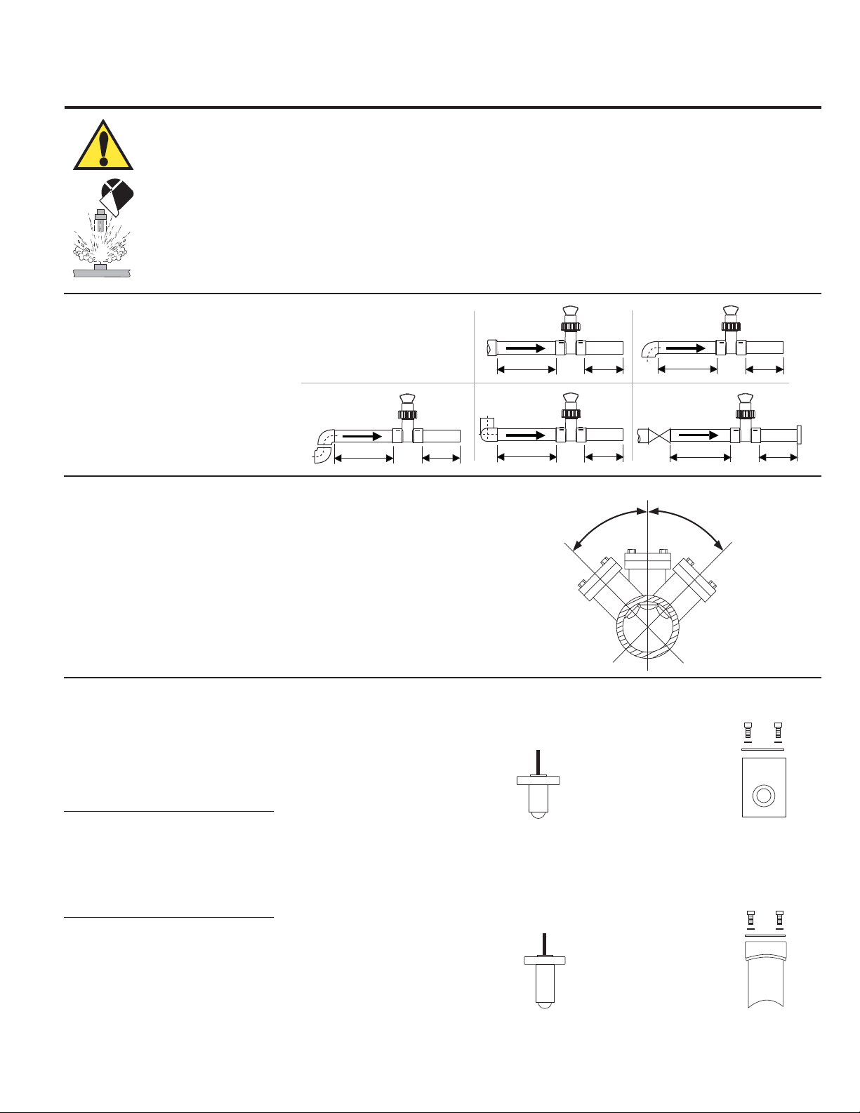
1. Location of Fitting
Recommended sensor upstream/downstream
mounting requirements.
2 x 90° Elbow
25x I.D. 5x I.D.
2. Sensor Mounting Position
• Horizontal pipe runs: Mount sensor in the upright (0°) position for
best overall performance. Mount at a maximum of 45° when air
bubbles are present. Do not mount on the bottom of pipe when
sediments are present.
Maximum Operating Temperature/Pressure:
Signet 525 Metalex Sensor with:
• Signet 526-1XXX Series Saddle Fitting:
21 bar @ 66 °C (300 psi @ 150 °F)
• Signet 526-2XXX Series Tee and Mini-Tap Fitting:
103 bar @ 149 °C (1500 psi @ 300 °F)
Reducer
15x I.D. 5x I.D.
2 x 90° Elbow
3 dimensions
40x I.D. 5x I.D.
45°
90° Elbow
20x I.D. 5x I.D.
Pump/Valve
50x I.D. 5x I.D.
45°
• Vertical pipe runs: Sensor must be mounted in lines with UPWARD
fl ow only.
3. Sensor/Fitting Selection
The 525 is designed for installation into SCH 40 stainless steel pipes
via the Signet Metalex Tee, Mini-Tap or Saddle fi ttings, see options
below:
Signet Metalex Tee Fittings (Sensor PN P525-1/-1S)
Pipe (in.) Fitting Code
0.50 P526-2005 198 840 501
0.75 P526-2007 198 840 502
1.00 P526-2010 198 840 503
Signet Metalex Mini-Tap Fittings (Sensor PN P525-2/-2S)
Pipe (in.) Fitting Code
1.25 P526-2012 159 000 494
1.50 P526-2015 198 840 506
2.00 P526-2020 159 000 495
2.50 P526-2025 159 000 496
3.00 P526-2030 159 000 497
4.00 P526-2040 159 000 498
5.00 P526-2050 159 000 499
6.00 P526-2060 159 000 500
8.00 P526-2080 159 000 501
10.0 P526-2100 159 000 502
12.0 P526-2120 159 000 503
Wetted fitting materials:
316 SS
+GF+
525-1
Sensor
(525-1S for stainless steel)
+GF+
525-2
Sensor
(525-2S for stainless steel pin)
Tee Fitting,
hardware included
Wetted fitting materials:
316 SS & 347 SS
Mini-Tap Fitting,
hardware included
Page 2
Signet Metalex Saddle Fittings (Sensor PN P525-3/-3S)
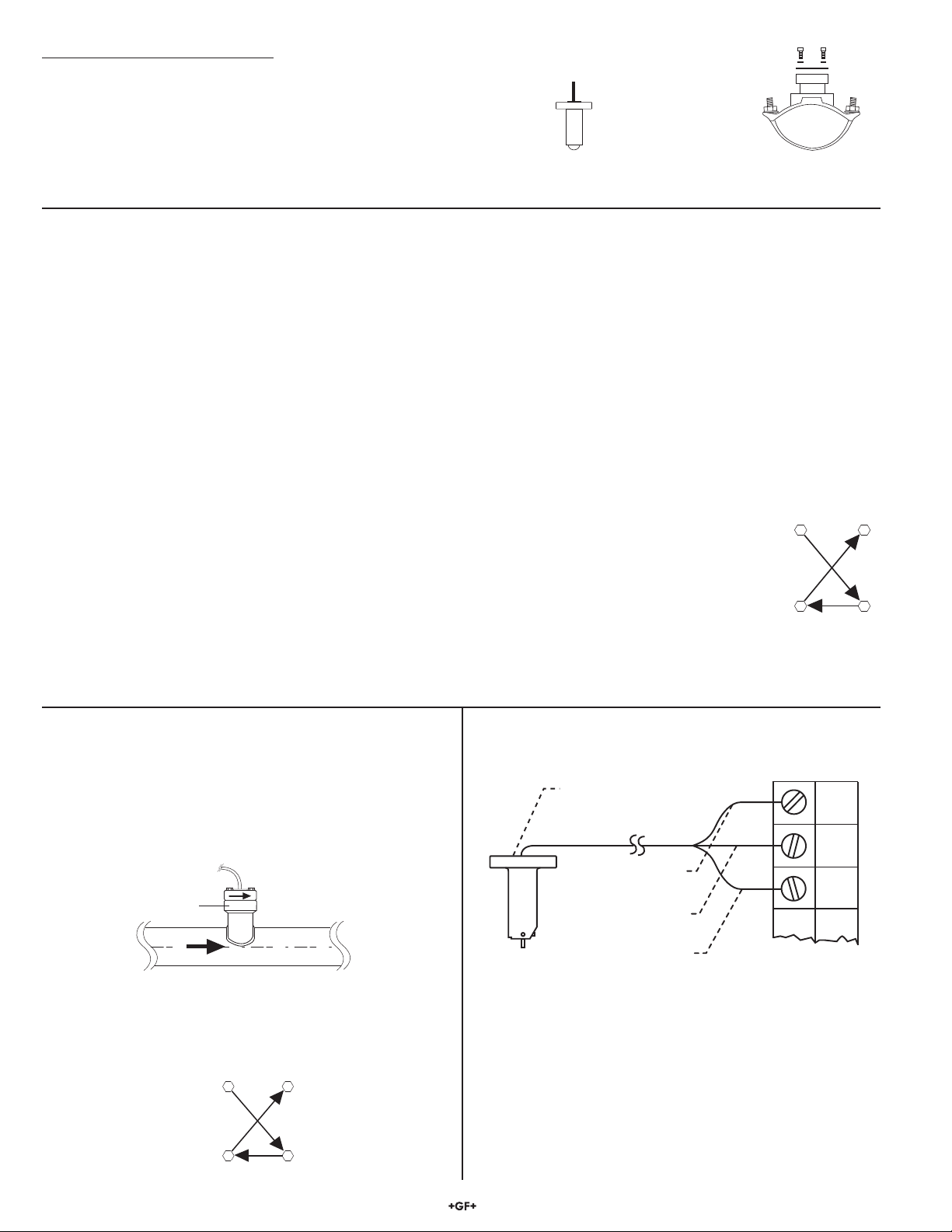
Blk
F-
Red
F+
Shld.
525
black
(AC signal out)
red
(AC signal out)
silver
(ground) Instruments
1/2 in. NPT
conduit port
14
23
Flange
bolt torque
pattern
Pipe (in.) Fitting Code
2.00 P526-1020 159 000 484
2.50 P526-1025 159 000 485
3.00 P526-1030 159 000 486
4.00 P526-1040 159 000 487
5.00 P526-1050 159 000 488
6.00 P526-1060 159 000 489
8.00 P526-1080 159 000 490
10.0 P526-1100 159 000 491
12.0 P526-1120 159 000 492
4. Fitting Installation, Required Hardware
Wetted fitting materials:
Ductile Iron, 347 SS,
Carbon Steel,
+GF+
525-3
Sensor
(525-3S for stainless steel pin)
Buna-N/Neoprene
Saddle Fitting,
hardware included
Signet Metalex Tee & Mini-Tap Fittings, P526-2XXX
• 0.5 to 1 inch pipes, P526-2 series fi tting required
• 1.25 to 12 inch pipes: P526-2 series fi tting and 27 mm
(1-1/16 in.) diameter drill required
• Mini-Tap fi ttings are welded onto the pipe and are used with
Signet 525-1 and 525-2 sensors.
Signet Metalex Saddle Fitting, P526-1XXX
• 27 mm (1-1/16 in.) diameter drill required
Saddle type fi ttings are strapped to the pipe and are used with
Signet 525-3 sensors. Welds MUST be made by a certifi ed welder
who is licensed to weld stainless steel and other high carbon
grade steels.
4.1 Installation, Tee & Mini-Tap Fittings
1. Select an appropriate mounting location as outlined in
sections 1 and 2.
2. Depressurize and drain pipe.
3. Use the following welding and installation procedures
appropriate for your fi tting/pipe size:
Signet Tee Fittings, 0.5 to 1 inch:
• Insert pipe into fi tting socket
• Make sure the pipe is parallel to the bottom of the Mini-Tap
fi tting.
• Weld pipe into place.
Signet Mini-Tap Fittings, 1.25 to 12 inch:
• Drill a 27 mm (1-1/16 in.) diameter hole completely through the
ONE surface of the pipe. Thoroughly deburr inner and outer
edges of hole.
• Tack weld the Mini-Tap fi tting onto the pipe, making sure the
hole in the pipe is lined up with the Mini-Tap fi tting hole.
• Weld the Mini-Tap fi tting onto the pipe.
4.2 Installation, Saddle Fittings
1. Select an appropriate mounting location as outlined in
sections 1 and 2.
2. Drill a 27 mm (1-1/16 in.) diameter hole completely through
the TOP surface of the pipe. Thoroughly deburr inner and
outer edges of hole.
3. Place the Buna-N/Neoprene saddle O-ring over the pipe hole
(small hole side towards pipe). Position the saddle fi tting
over the O-ring, making sure the O-ring
centers on the underside fi tting ridge.
Center saddle fi tting and O-ring over the
pipe hole, then strap the fi tting to the pipe
with the two U-bolts. Snug all four nuts
in a criss-cross pattern. Using a torque
wrench (when possible), torque the
U-bolts in a criss-cross pattern to 52 foot pounds.
14
U-bolt
torque
pattern
23
5. Sensor Installation
1. Set the gasket supplied with the fi tting onto the fi tting fl ange,
making sure the holes align.
2. Remove the red rotor protection cap and insert the sensor
into the fi tting, making sure not to bump the rotor assembly.
Make sure the arrow on the side of the sensor is pointing in
the direction of fl ow.
Fitting
flange
Flow sensor
arrow
6. Sensor Wiring
Flow
3. Slip two washers onto each bolt and insert the bolt/washer
onto each of the four fi tting fl ange holes.
4. Snug all four fl ange bolts in a criss-cross pattern. Using a
torque wrench (when possible), torque the fl ange nuts in a
crisscross pattern to 52 foot pounds.
• Use 2-conductor shielded cable for cable splices to 60 m
(200 ft).
• Maintain cable shield through splice.
• Shield the unjacketed silver (ground) wire using electrical tape
to prevent potential noise interference and/or shorting hazards.
2 Signet 525 Metalex Flow Sensor
Page 3

7. Sensor Removal Procedure
Rotor Pin
1. Depressurize and drain pipe.
2. Remove the four sensor fl ange bolts and lock washers. Pull
upward on the sensor fl ange with an alternating twisting
motion.
WARNING!
Do not remove from pressurized lines.
Wear safety goggles and faceshield
during installation/service.
8. Maintenance
The 525 sensor requires little or no maintenance of any kind, with the exception of an occasional sensor/paddlewheel cleaning.
9. Rotor Replacement Procedure
1. With a small pair of needle-
nose pliers, fi rmly grip the
center of the rotor pin (axle)
and with a twisting motion,
bend the rotor pin into an
"S" shape. This should pull
the ends of the pin out of the
retainers and free the rotor
assembly.
2. Remove rotor pin retainer from
each side by gently tapping it
inwards using a punch. Install a
new retainer into the sensor body
with its rotor pin clearance hole
inward. Only install one retainer at
this time.
10. K-Factors
Retainer
Punch
3. Insert the new rotor assembly
and bearings into the rotor
housing of the sensor and
place the new rotor pin (axle)
through the open end of
the rotor housing, through
the rotor and bearings, and
into the previously installed
retainer.
4. Using a vise or C-clamp, press
the second retainer into the hole
in the sensor body while lining
up the rotor pin with the center
of the retainer hole.
NOTE: A hammer and center punch
can also be used if a clamp or vice
is not available
Existing
Retainer
Rotor Pin
New
Bearings
Rotor
Assembly
The K-Factor is the number of pulses the sensor will generate for each engineering unit of fl uid which passes. They are listed in U.S.
gallons and in liters. For example, in a 1 inch SCH 40S stainless steel pipe, the sensor generates 266.17 pulses per gallon of fl uid
passing the rotor. K-Factors are listed for SCH 40S stainless steel pipes up to 12 inch.
SCH 40S STAINLESS STEEL PIPE PER ANSI B36.19
PIPE
SIZE
K-FACTOR
PULSES/
U.S. GAL
K-FACTOR
PULSES/
U.S. LITER
A-FACTOR
GPM/Hz
A-FACTOR
LPM/Hz
1/2 IN. 873.03 230.66 0.0687 0.2601
3/4 IN. 515.41 136.17 0.1164 0.4406
1 IN. 266.17 70.322 0.2254 0.8532
Conversion Formulas
1 U.S. gallon = 0.003785 cubic meters
0.000003069 Acre feet
8.3454 pounds of water
1 1/4 IN. 148.84 39.324 0.4031 1.5258
1 1/2 IN. 107.98 28.528 0.5557 2.1032
2 IN. 64.808 17.122 0.9258 3.5042
2 1/2 IN. 44.685 11.806 1.3427 5.0822
3 IN. 28.579 7.5506 2.0994 7.9464
4 IN. 16.302 4.3070 3.6805 13.931
5 IN. 10.237 2.7046 5.8611 22.184
6 IN. 7.0057 1.8509 8.5645 32.416
8 IN. 3.9641 1.0473 15.136 57.289
10 IN. 2.4690 0.6523 24.301 91.981
12 IN. 1.6894 0.4463 35.516 134.43
3Signet 525 Metalex Flow Sensor
Page 4

11. Specifi cations
retainer retainer
rotor pin
bearing
bearing
rotor
General
Operation Range: 0.5 to 6 m/s (1.6 to 20 ft/s)
(depending on pipe size)
Pipe Size Range: DN15 to DN300 (½ to 12 in.)
Linearity: ±1% of max. range @ 25 °C (77 °F)
Repeatability: ±0.5% of max. range @ 25 °C (77 °F)
Wetted Materials
Sensor Body: 316 SS (ACI type CF-8M per ASTM
A351), DIN 17440
Rotor Material: CB7Cu-1 Alloy
Rotor Pin: Tungsten Carbide GRP 1 or 316 SS
Retainers (2): 316 stainless steel (1.4401)
Rotor Bearings (2): Rulon
Gasket: KLINGER® sil C-4401 (supplied with fi tting)
®
B (Fluoroloy/PTFE)
Electrical
Frequency: 12 Hz per ft/s nominal
Amplitude: 5 to 8 mV p-p per Hz
Source Impedance: 11.6 KΩ
Coil Inductance: 3.5 Henrys @ 25 °C
Cable Length: 7.6 m (25 ft), can be extended up to 60 m
(200 ft)
Cable Type: 22 AWG, 2-conductor w/shield
Maximum Temperature/Pressure Rating
Socket Weld or Weld-On Mini-Tap fi ttings:
103 bar (1500 psi @ safety factor 1.5) @ 149 °C (300 °F)
• Strap-on Saddle fi tting:
21 bar (300 psi) @ 66 °C (150 °F)
Operating Temperature:
-18 to 149 °C (0 to 300 °F)
Standards and Approvals
• Manufactured under ISO 9001 for Quality, ISO 14001
for Environmental Management and OHSAS 18001 for
Occupational Health and Safety.
• RoHS compliant
China RoHS (Go to www.gfsignet.com for details)
Chemical Compatibility
Signet products are manufactured in a variety of wetted materials to suit various liquids and chemicals.
All plastic materials including typical piping types (PVC, PVDF, PP and PE) are more or less permeable to contained media, such as
water or volatile substances, including some acids. This effect is not related to porosity, but purely a matter of gas diffusion through the
plastic. If the plastic material is compatible with the medium according to the application guidelines, the permeation will not damage the
plastic itself. However, if the plastic encloses other sensitive components, as is the case with Signet plastic paddlewheel sensors, these
may be affected or damaged by the media diffusing through the plastic body and rotor.
PVDF paddlewheel sensor failure when used in hot nitric acid applications has been reported. PVDF is known to allow for substantial
permeation of nitric acid constituents without being damaged itself. No clear guideline can be given here, since the damaging effect
to the sensor is highly dependent on temperature, pressure and concentration. Utilizing sensors in applications with aggressive
substances is possible. On special request Signet can provide sensors with a different internal resin encapsulation (potting) that will
delay the damaging effect of acids to the sensors. For all Special Product inquiries or to place an order, please contact Signet.
Accessories and Replacement Parts
Code Description
198 801 501 P52509 Rotor kit (rotors, 316 stainless steel pin, Rulon® B bearings, SS retainers
159 000 480 P52509-2 Rotor kit (rotors, Tungsten Carbide GRP1 pin, Rulon® B bearings, SS retainers
198 801 500 P52504-1 Rotor Pin, Stainless steel (1.4401) (optional)
198 820 023 P52504-2 Rotor Pin, Tungsten Carbide (standard)
159 000 493 P52618 Gasket
198 820 013 P52503 Bearing, Rulon® B (Fluoroloy/PTFE)
159 000 481 P52527 Retainers, Stainless steel
159 000 504 P52628 Fitting cap kit (cap and gasket)
159 000 476 P51589 Conduit adapter kit
159 000 393 5523-3222 Cable (per foot) 2 cond. w/shield, 22 AWG
P52509/P52509-2 Rotor kit
Georg Fischer Signet LLC, 3401 Aero Jet Avenue, El Monte, CA 91731-2882 U.S.A. • Tel. (626) 571-2770 • Fax (626) 573-2057
For Worldwide Sales and Service, visit our website: www.gfsignet.com • Or call (in the U.S.): (800) 854-4090
For the most up-to-date information, please refer to our website at www.gfsignet.com
P52590-1 Rev. P 10/12 English © Georg Fischer Signet LLC 2012
 Loading...