

Page 1
Signet 4630 Free Chlorine Analyzer System
Signet 4632 Chlorine Dioxide Analyzer System
*3-463X.090*
3-4630.090 Rev L 09/13
The Signet 4630 and 4632 Systems are EPA 334.0 Compliant.
Description
The Signet Chlorine Analyzer Systems are integrated, all-in-one chlorine panel systems
Signet
Chlorine Analyzer
designed to measure Free Chlorine or Chlorine Dioxide in drinking water and clean, fresh
water treatment applications.
This manual includes the 4630 Free Chlorine and 4632 Chlorine Dioxide Analyzer Systems.
Features:
• EPA 334.0 Compliant: The 4630 Free Chlorine and 4632 Chlorine Dioxide systems can
be used for reporting chlorine residuals in accordance with EPA Method 334.0.
• Complete chlorine analyzer system allows quick setup and easy installation. Connect
to a water source and plug it in.
• Unique integrated clear ow cell combines sensors, ow regulator, lter and variable
area ow indicator in one compact unit.
• Built-in variable area ow indicator facilitates ow rate con rmation at a glance.
• Integrated ow regulator with removable lter accepts inlet pressures of 1 to 8 bar
(15 to 120 psi) while maintaining constant ow and minimal pressure to the sensors.
• Water ows vertically into sensor tip, eliminating bubble entrapment. Raised exit in ow
cell sensor chamber ensures sensors stay submerged even when system and ow is
turned off.
• Flow cell accommodates two sensors; one chlorine and an optional pH sensor.
• Automatic pH and temperature compensation or manual pH value input capability for
accurate free chlorine readings.
• Easy viewing of the transmitter via the bright backlit LCD display.
• Moisture-proof NEMA 4X wiring enclosure.
English
Operating Instructions
Additional information can be found in the individual product manuals,
refer to www.gfsignet.com.
Click on Product Manuals under the Signet Quick Links section.
• 3-8630-3P Chlorine Transmitter Manual (3-8630.090-3)
• 3-2630 Series Amperometric Chlorine Electrode Manual (3-2630.090)
• 3-2650 Amperometric Electronics Manual (3-2650.090)
• 3-2724 pH/ORP Electrode Manual (3-2724.090)
• 3-2750 pH Electronics Manual (3-2750.090)
Safety
CAUTION!
1. Follow instructions carefully to avoid personal injury.
2. Do not exceed the maximum pressure or temperature speci cations.
3. Mounting the Chlorine System in an outdoor box, in areas with elevated temperatures,
may cause damage to the system if the enclosure's internal temperature exceeds the
temperature speci cation of the Chlorine Analyzer.
4. Do not alter product construction.
5. For use with clean fresh water only.
6. Disconnect AC power before opening wiring enclosure.
7. This panel system uses AC voltages. Wiring should be done by quali ed personnel only.
Page 2
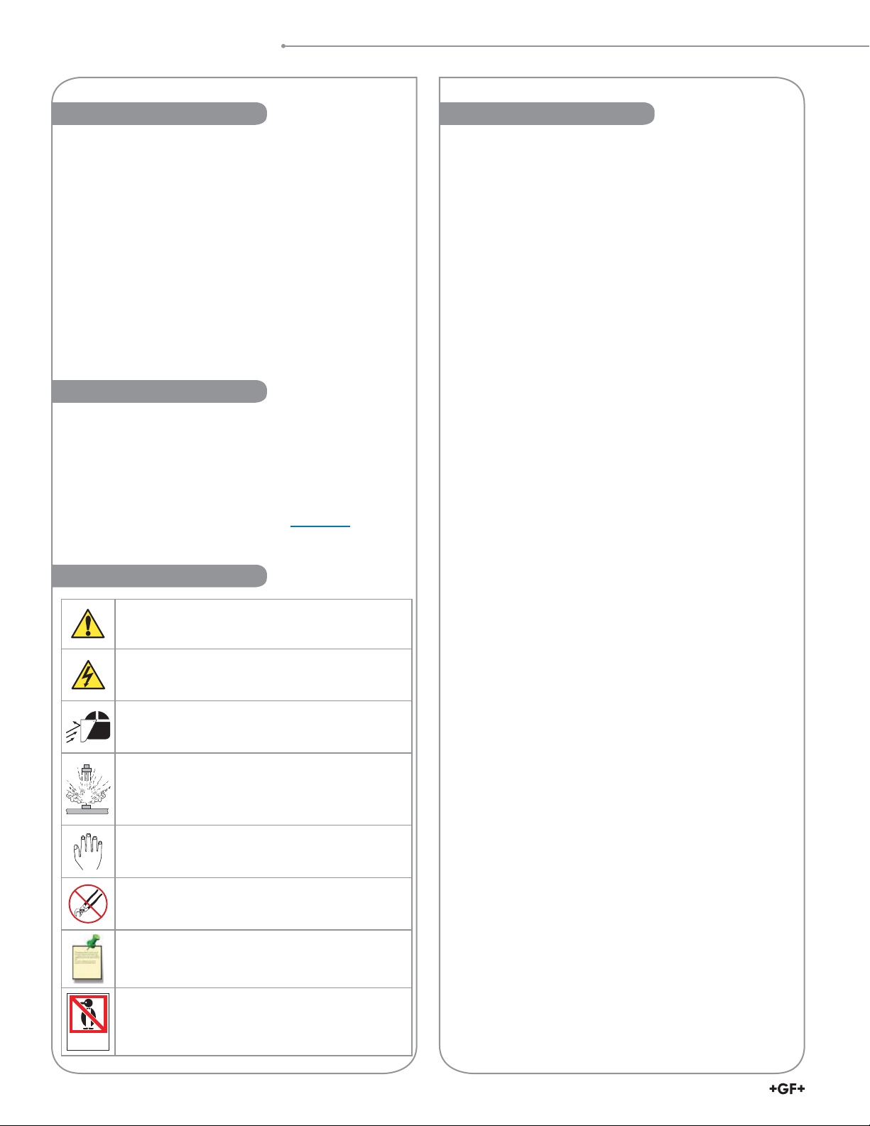
Table of Contents
Warranty Information Table of Contents
Refer to your local Georg Fischer Sales of ce for the most
current warranty statement.
All warranty and non-warranty repairs being returned must
include a fully completed Service Form and goods must be
returned to your local GF Sales of ce or distributor.
Product returned without a Service Form may not be
warranty replaced or repaired.
Signet products with limited shelf-life (e.g. pH, ORP, chlorine
electrodes, calibration solutions; e.g. pH buffers, turbidity
standards or other solutions) are warranted out of box but not
warranted against any damage, due to process or application
failures (e.g. high temperature,
or mishandling (e.g. broken glass,
chemical poisoning, dry-out)
damaged membrane,
freezing and/or extreme temperatures).
Product Registration
Thank you for purchasing the Signet line of Georg Fischer
measurement products.
If you would like to register your product(s), you can now
register online in one of the following ways:
• Visit our website www.gfsignet.com and
click on Product Registration Form
• If this is a pdf manual (digital copy),
click here
• Scan the QR Code on the left
Safety Information
Warning / Caution / Danger
Indicates a potential hazard. Failure to follow all warnings
may lead to equipment damage, injury, or death
Electrostatic Discharge (ESD) / Electrocution Danger
Alerts user to risk of potential damage to product by ESD,
and/or risk of potential of injury or death via electrocution.
Personal Protective Equipment (PPE)
Always utilize the most appropriate PPE during
installation and service of Signet products.
Pressurized System Warning
Sensor may be under pressure, take caution to vent
system prior to installation or removal. Failure to do so
may result in equipment damage and/or serious injury.
Hand Tighten Only
Overtightening may permanently damage product
threads and lead to failure of the retaining nut.
Do Not Use Tools
Use of tool(s) may damage product beyond repair and
potentially void product warranty.
Note / Technical Notes
Highlights additional information or detailed procedure.
Description ............................................................................... 1
Warranty Information ................................................................ 2
Product Registration ................................................................ 2
Safety Information .................................................................... 2
Chlorine System Dimensions ................................................... 3
Chlorine System Speci cations ............................................... 3
4630 Chlorine Analyzer System Inventory............................... 4
Quick Start ............................................................................... 4
Panel Assembly........................................................................ 5
Component Identi cation: Flow Cell ........................................ 6
Mounting .................................................................................. 7
Wiring Input .............................................................................. 8
Wiring Output ........................................................................... 9
Electrical Box Wiring Schematic ............................................ 10
Chlorine Sensor Preparation ..................................................11
Chlorine Sensor Calibration ....................................................11
Chlorine Sensor Maintenance ................................................11
Sensor Installation.................................................................. 12
Tubing Connections ............................................................... 13
Water Flow ............................................................................. 13
8630 Chlorine Transmitter...................................................... 14
View Mode .......................................................................... 14
Editing Procedure ............................................................... 15
Calibrate Menu ................................................................... 17
Options Menu ..................................................................... 20
Chlorine Sensor Conditioning ............................................ 22
pH Sensor Calibration ........................................................ 22
Chlorine Sensor Calibration ............................................... 24
Output Settings - Loops and Relays .................................. 25
2650-7 DryLoc® Amperometric and 2750-7 pH Electronics ... 28
Wiring to the Signet 8630 Chlorine Transmitter ................. 28
Chlorine Electrode Overview ................................................. 29
2630 and 2632 Amperometric Chlorine Electrodes ........... 29
Calibration .......................................................................... 30
Maintenance ....................................................................... 30
2724 DryLoc pH Electrode ..................................................... 31
Calibration .......................................................................... 32
Appendix ................................................................................ 33
Maintenance - 463X Chlorine Analyzer Flow Cell ............. 33
Maintenance - 2630 Free Cl / 2632 ClO
Electrode .......... 36
2
Maintenance - 2724 DryLoc pH Electrode ......................... 38
Troubleshooting - 463X Chlorine Analyzer ........................ 39
Troubleshooting - 8630 Chlorine Transmitter .................... 40
8630 Transmitter Error Messages...................................... 41
Troubleshooting - 2630 Free Cl / 2632 ClO
Electrode ..... 43
2
Troubleshooting - 2750-7 pH Electronics........................... 43
Speci cations ......................................................................... 44
Ordering Information .............................................................. 48
Do Not Freeze
Products are temperature sensitive and may contain
DO NOT
FREEZE
2
freezable liquids. Freezing damage to pH, ORP, and
Chlorine electrodes voids product warranty.
463X Chlorine System Manual
Page 3
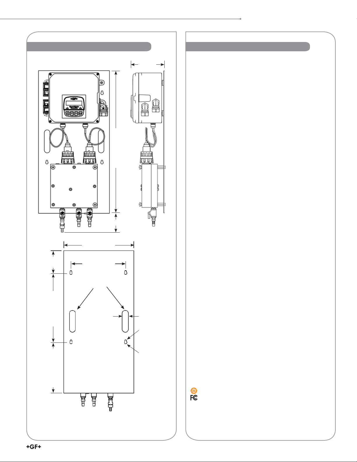
Speci cations and Dimensions
Chlorine System Dimensions Chlorine System Speci cations
79.3 mm (3.12 in.)
305 mm (12 in.)
165 mm
(6.5 in.)
578 mm (22.75 in.)
General
Compatible Signet Sensors:
• 3-2630-1 Free Chlorine Sensor 0-2 ppm
• 3-2630-2 Free Chlorine Sensor 0-5 ppm
• 3-2630-3 Free Chlorine Sensor 0-20 ppm
• 3-2632-1 Chlorine Dioxide Electrode 0-2 ppm
• 3-2724-00 Flat pH Electrode
Materials:
Panel: .......................................Black acrylic
Flow Cell: ..................................Acrylic
Wiring Enclosure: .....................Polycarbonate
Wetted Materials:
Flow cell, spacer rings: ............. Acrylic
Flow regulator housing ............. Polycarbonate
Strainer, e-clip, regulator spring,
oat: ........................................ Stainless steel
Valves, vent: .............................Polypropylene
Flow cell O-rings, diaphragm: ...EPDM, FKM
Chlorine electrode ....................PVC, PVDF or PTFE, FPM
pH electrode .............................
PPS, Glass, UHMW, PE, FPM
Sealing tape (valves, plug, vent) .. PTFE
Plug ..........................................Polyethylene
Performance
System Inlet Pressure Rating: .. 1 to 8 bar (15 to 120 psi)
Pressure Regulator:..................< 0.69 bar (10 psi) variation
over all ranges of ow and
pressure
Flow tolerance .......................... ±15% or rated speci cation
above
Flow rate limits ............................. 8 to 12 gph (US)
(30.24 to 45.36 LPH)
(3 in.)
76 mm
254 mm (10 in.)
Hand Holds
25 mm
330 mm (13 in.)
171 mm (6.75 in.)
Material Safety Data Sheets (MSDS) are available online
at www.gfsignet.com.
(1.0 in.)
Ø 7 mm
(0.27 in.)
Ø 13 mm
(0.52 in.)
Electrical
AC Input (standard): .................
DC Input (optional): ....................
100 to 240 VAC nominal
50 to 60 Hz, 0.17 A at 100 VAC
12 to 24 VDC ±10% regulated,
10 W, 250 mA max
Environmental Requirements
Storage Temperature: ...............
Operating Temperature: ............
Relative Humidity:.....................0 to 95%
Maximum Altitude: .................... 6562 ft (2000 m)
Shipping Weight: ......................22 lbs (10 kg)
Enclosure:.................................NEMA 4X (with output wire
0 °C to 65 °C (32 °F to 149 °F)
0 °C to 45 °C (32 °F to 113 °F)
glands sealed)
Standards and Approvals
• CE, UL, CUL, WEEE
• RoHS Compliant
• Manufactured under ISO 9001 for Quality,
ISO 14001 for Environmental Management and
OHSAS 18001 for occupational health and safety.
China RoHS (Go to www.gfsignet.com for details)
Declaration of Conformity according to FCC Part 15
This device complies with Part 15 of the FCC rules.
Operation is subject to the following two conditions:
(1) This device may not cause harmful interference, and,
(2) This device must accept any interference received,
including interference that may cause undesired operation.
3463X Chlorine System Manual
Page 4
System Inventory
4630 Chlorine Analyzer System Inventory
1. Chlorine panel assembly
a. Built-in pressure regulator 15 to 120 psi.
b. 3/8 inch hose barb connectors.
2. 1 each 2630 series Free Chlorine sensor or 2632 Chlorine Dioxide sensor; each with protective cap
a. 1 spare membrane cap
b. 2 bottles of electrolyte solution
c. 1 syringe needle (taped to bottle)
d. 1 syringe
3. 1 each Flat pH sensor 3-2724-00 (159 001 545) (3-4630-11, -21, -31 and 3-4632-11 models only)
4. Manual package
a. English panel assembly manual
b. CD with multi-language manuals
c. Wall mounting hardware
d. Drill template
5. 1 each North American Type B power cord
6. Customer supplied
a. 3/8" hose input and drain
b. Hose clamps
Quick Start
Follow the steps below to set up a new Chlorine Analyzer System. Refer to the individual component manuals for detailed information.
Step 1. Mount the panel on a vertical at surface using appropriate hardware.
Do not turn on power at this time.
Step 2. Open the wiring enclosure and wire input power
(see page 8: Wiring Input, page 9: Wiring Output, and page 10: Electrcial Box Wiring Schematic).
Step 3. Wire any 4 to 20 mA and relay output.
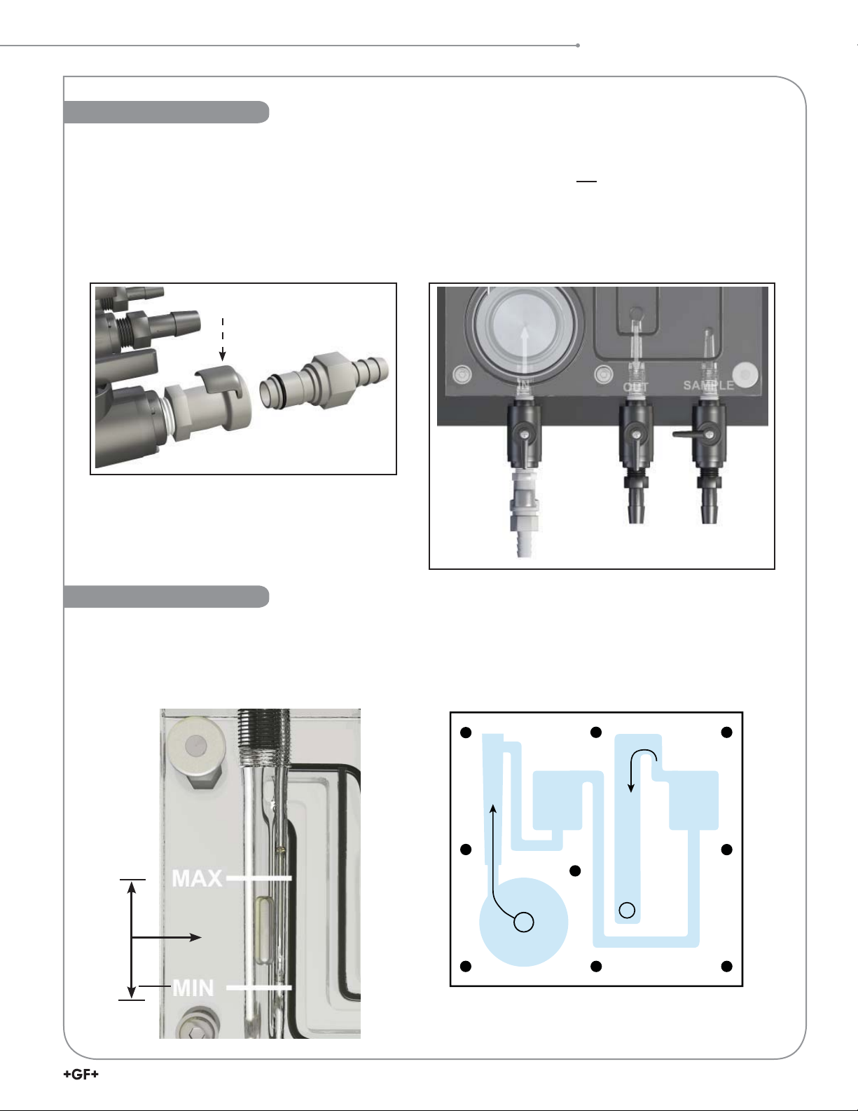
Step 4. Remove sensor access plugs from the ow cell (Figure 1).
If the optional pH sensor is NOT used, do not remove the left-side plug from the ow cell.
Step 5. Remove the protective cap from the chlorine electrode.
(Keep the electrode cap in a safe place for future use. It is recommended to use the cap to protect the sensor during
the removal of the electrode for cleaning or maintenance of the ow cell).
Step 6. Complete Sensor Preparation (see page 11) and install the chlorine sensor into the electronics
(see page 12: Sensor Installation). Install the chlorine electrode into the ow cell.
The chlorine sensor is installed in the right-side access port, optional pH sensor is installed in the left-side access port.
NOTE:
NOTE: If a Chlorine Dioxide sensor or a Free Chlorine sensor without optional pH sensor is used, pH value must be
Step 7. Repeat step 5 and 6 if the optional pH sensor is being used.
Step 8. Install the in uent water source to the "Inlet Port" nipple assembly of the ow
Step 9. Install 3/8-inch tubing and secure with a hose clamp on the "Drain" port and
Step 10. Verify the inlet and drain ball valves are in the open position and
Step 11. Turn on the in uent water source and check the system for leaks.
Step 12. Apply power to the system and allow system to initialize. Calibrate per instructions
NOTE: As factory default, the 4630-X Chlorine Panel Assembly is set to measure Free Chlorine. If a 2632 Chlorine Dioxide
All new chlorine and pH sensors require calibration during the start up of a system and throughout the life of the sensor.
A new chlorine sensor requires a conditioning period of up to 4 hours with power on and chlorinated water owing past
the sensor prior to calibration. See page 24: Chlorine Sensor Calibration, for chlorine calibration and set up procedure.
"hard-coded" into the system (See page 23: Manual pH compensation).
If optional pH sensor is installed, see page 22 to complete pH Sensor Calibration.
Sensor access plugs
cell. Install 3/8-inch tubing and secure with a hose clamp.
(Not included. See page 13: Tubing Connections)
direct the tube to a proper drain. (Not included)
the sample port is in the off position (See page 13: Tubing Connections).
(See page 24: Chlorine Sensor Calibration and page 22: pH Sensor Calibration).
sensor is to be used to convert to a Chlorine Dioxide Panel Assembly, refer to the 8630-3 OPTIONS Menu on page 20.
Figure 1
4
463X Chlorine System Manual
Page 5
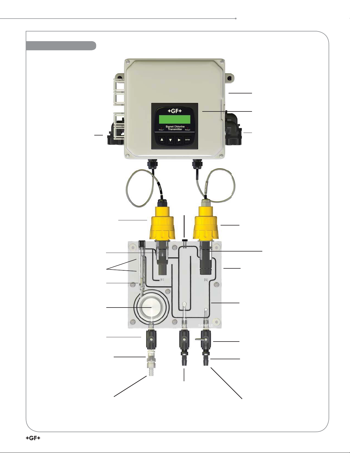
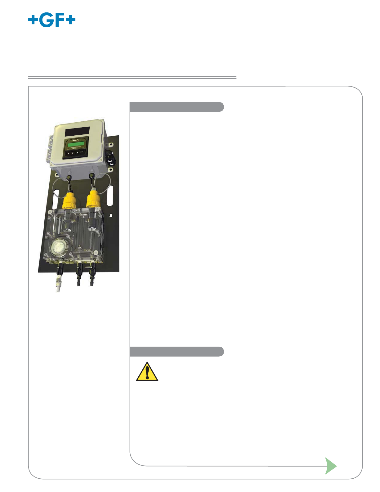
Panel Assembly
Panel Assembly
Wiring enclosure
Transmitter
3-8630-3P (159 001 673)
Power cable conduit
pH sensor
electronics
3-2750-7 (159 001 671)
pH electrode
3-2724-00 (159 001 545)
Flow range limits
Flow rate indicator
Vent
Cap
Output conduits
Amperometric chlorine
sensor electronics
3-2650-7 (159 001 670)
Chlorine electrode
3-2630-X (Free Chlorine)
3-2632-1 (Chlorine Dioxide)
Flow cell block
Flow regulator with strainer
Inlet port
Quick disconnect
2000-2525*
Quick disconnect plug
(3/8 inch hose)
2000-3825*
Drain port
(3/8 inch hose)
* Contact factory for quote
Flow cell O-rings
3/8" Ball valve
4300-5225*
3/8" Hose barb
2000-3804*
Sampling port
5463X Chlorine System Manual
Page 6
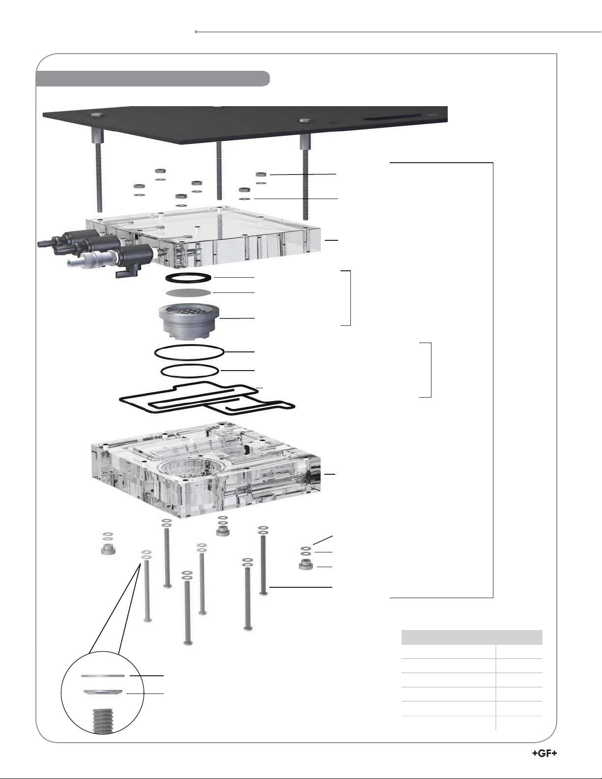
Component Identi cation
Component Identi cation: Flow Cell
Spacer ring
Stainless steel lter
Pressure regulator
Flow cell nut
Flat washer
Flow cell back block
Regulator Assembly
(3-4630.391)
(159 001 689)
Pressure regulator outer O-ring (large)
Pressure regulator outer O-ring (small)
Flow cell O-rings (4 segments)
Flow cell front block
Flat washer*
Disc spring (2700-0003)*
Knurled thumb nut (1700-2512)*
Flow cell bolt (2490-0554)
*Not included with
3-4630.392 (159 001 690)
Flow Cell
Rebuild Kit
(3-4630.390)
(159 001 688)
3-4630.392
(159 001 690)
Included in kit 3-4630.390
Item Quantity
Flow cell nut 6
Flat washer
Disc spring (curved washer)
6
463X Chlorine System Manual
Flat washer 15
Disc spring 9
Knurled thumb nut 3
Flow cell bolt 6
Page 7
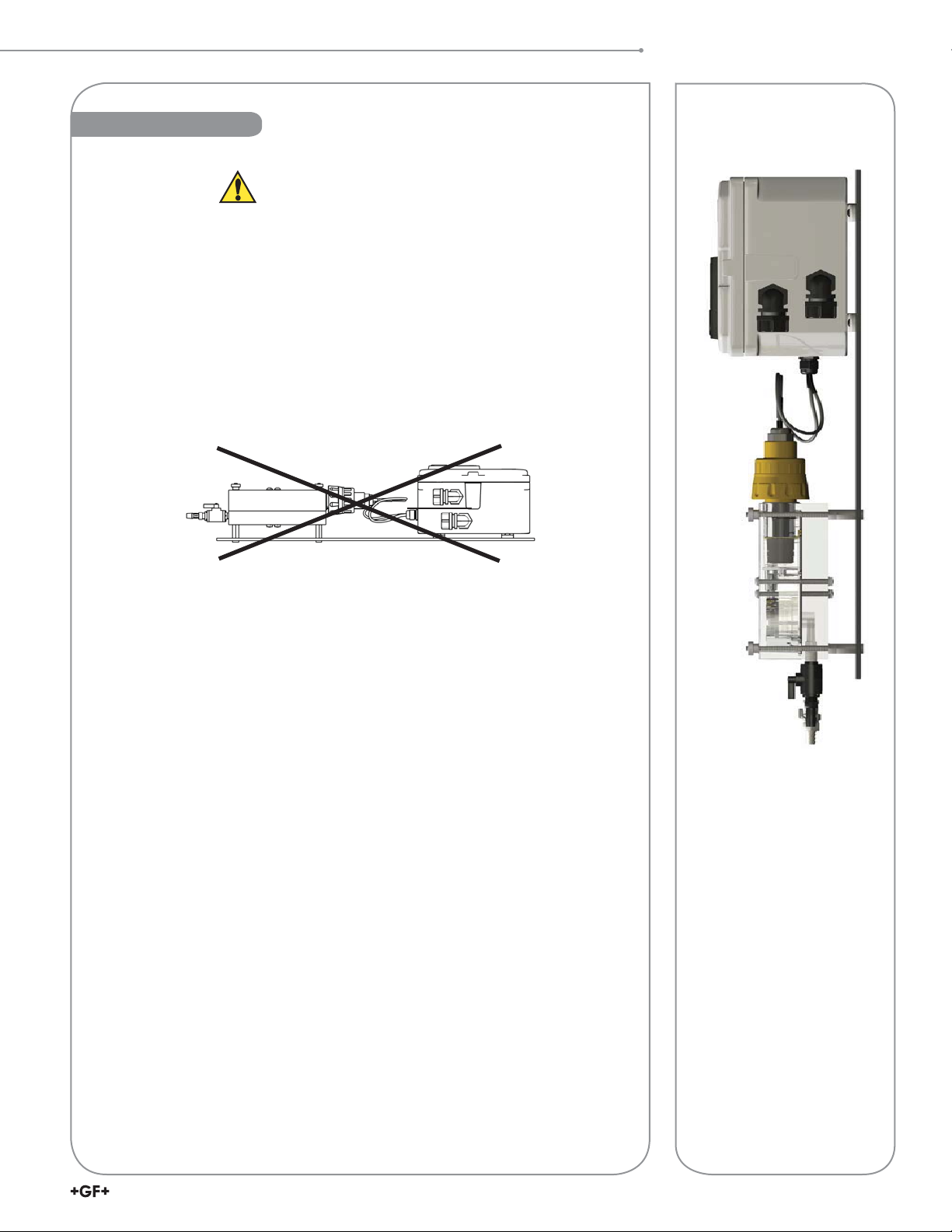
Mounting
Do not mount in direct sunlight.
• Bright light can promote algae growth. Indoor mounting is recommended.
• If the system is mounted outdoors, an outdoor enclosure for the whole system must be
used to protect the electronics and ow cell from light, rodents, insects and dirt.
• Mount the panel according to local electrical, building, and/or plumbing codes and
seismic requirements.
• Use four 6 mm (¼ in.) diameter screws or bolts of suf cient length to mount the panel to
a sturdy vertical surface. A mounting template is provided.
• Allow clearance on the sides and bottom for service to the unit.
• Keep panel system electronics and enclosure away from dripping water.
• The panel must be mounted vertically in an upright position.
Mounting
NO
7463X Chlorine System Manual
Page 8
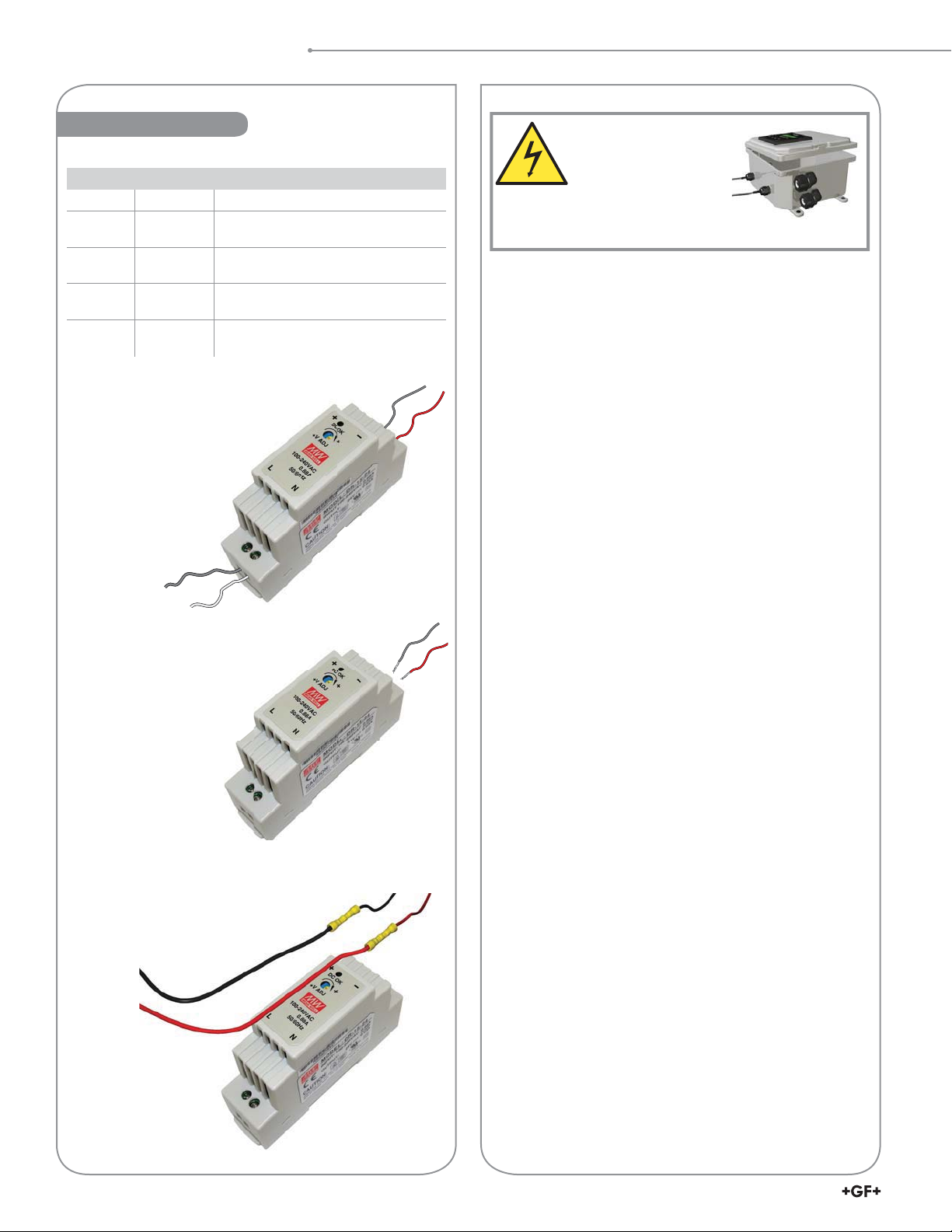
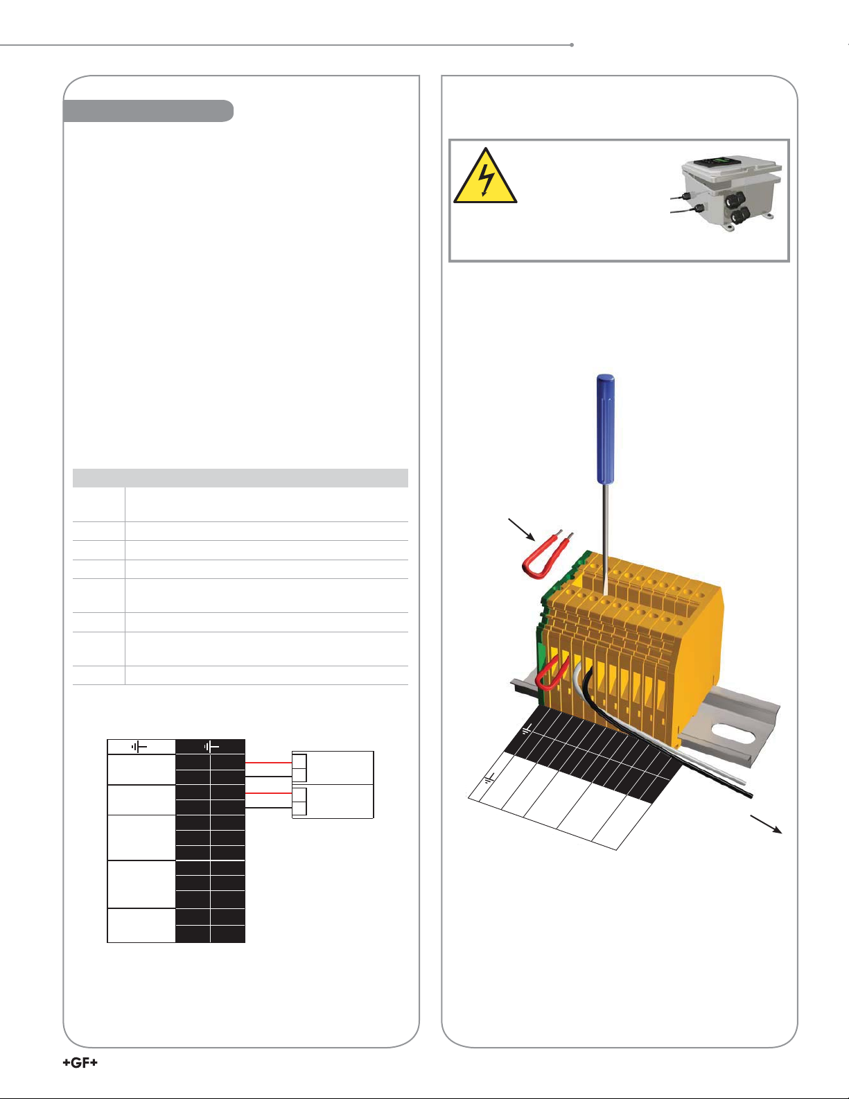
Wiring Input
Wiring Input
Power Supply Terminal Identi cation
Terminal Name Description
V. ADJ Voltage
DC ON Operation
+V, –V DC output
L, N Input
100 to 240 VAC input
Standard AC con guration
adjustment
indicator
terminals
terminals
Input for
100-240 VAC
Adjusts within ±10%; turning clockwise
increases output voltage
Green LED is lit when output voltage
is on
+V: Positive output terminal
–V: Negative output terminal
Accepts a wide range of voltages and
frequencies (100 to 240 VAC DC input)
Figure 2
Figure 3
WARNING
This panel system is
wired for AC voltages
that can injure or kill.
Wiring should be performed by
quali ed personnel only.
Disconnect AC power before opening wiring enclosure.
Follow all local and government recommendations and
methods for installation of electrical connections to and
between the system and other devices.
System Input Power
• The panel system is pre-wired with an auto switching power
supply that is rated for 100 to 240 VAC 50/60 Hz input.
• Wire with NEC Class I, 300 volt, 105 C wire.
• A switch or circuit breaker rated at 15 amps AC shall be
included in the building installation.
• Install the circuit breaker in close proximity to the
equipment and within easy reach of the operator.
• Mark the circuit breaker as the disconnecting device for
the equipment.
• Grounding: The protective ground terminal must be
bonded to protective earth in the host equipment.
Part # 7300-0024 (159 001 693) shown.
Actual power supply may differ from Figure 2.
100 to 240 VAC Input Wiring
• Open the electrical box by loosening the four corner
screws of the front cover.
• Insert input power wiring into the pre-drilled access hole
on the left side of the electrical box using appropriate
conduit adapters to maintain the Type 4X rating. (Supplied
conduit connectors may have to be removed.)
• Install the input power wires into the proper terminals
on the power supply (Figure 2). Use only 12 to 26 AWG
copper wiring.
• Recommended torque for the terminals is 7 lb-in.
NOTE: When using alternate power supply
7300-7524 (159 000 687):
• Use 10-24 AWG copper wiring, 105 C, torque 4.4 lb-in.
12 to 24 VDC Input Wiring Conversion
• If the power source supplied to the system will be 12 to
24 VDC instead of 100 to 240 VAC, disconnect the red
and black output wires from the power supply (Figure 3)
and connect your UL approved limited-energy DC power
supply (Figure 4), using an insulated nylon parallel splice
–
+
connector such as T&B part number 2C-12 or equivalent.
• Insert input power wiring into the pre-drilled access hole
on the left side of the electrical box using the appropriate
conduit adapters to maintain the Type 4X rating.
(Customer may have to remove the supplied conduit
connectors.)
• A switch or circuit breaker rated at 5 amps DC shall be
included in the building installation.
• Install the circuit breaker in close proximity to the
equipment and within easy reach of the operator.
Figure 4
8
463X Chlorine System Manual
• Mark the circuit breaker as the disconnecting device for
the equipment.
Page 9
Wiring Output
Wiring Output
Follow all local and government recommendations and
methods for installation of electrical connections to and
between the system and other devices.
Output Connections
• Use the wiring enclosure terminal block for output wire
connections. Do not wire directly to the transmitter.
• Recommended torque for the terminals is 7 lb-in
• Do not run 4 to 20 mA loop cables in the same conduit as
the power or other high voltage wiring.
• Remove one installed jumper wire (from both of its terminals)
on the terminal block in the enclosure for each loop device
connected. Replace the jumper if you later remove your
loop device. If only one loop device is connected, remove
just one jumper wire from its two terminals.
• The panel system uses an active loop output wired to the
enclosure terminal block.
• If connecting to a PLC, use the PLC's passive input.
• The transmitter must have a jumper wire or loop
device always connected to Loop 1.
Wiring Label Legend
Ground
Earth Ground. Attach 4 to 20 mA loop cable
shield wire here to help eliminate possible noise.
Loop 1 4 to 20 mA Loop #1
Loop 2 4 to 20 mA Loop #2
Relay 1 Relay Output #1
NC
Relay Normally Closed (contact) when
de-energized
C Common
NO
Relay Normally Open (no contact) when
de-energized
Relay 2 Relay Output #2 (terminals same as Relay #1)
WARNING
This panel system is
wired for AC voltages
that can injure or kill.
Wiring should be performed by
quali ed personnel only.
Disconnect AC power before opening wiring enclosure.
Wiring a 4 to 20 mA loop device
Jumper wire removed
1 2 3 4 5 6 7 8 9 10 11 12
+
LOOP 1
–
+
LOOP 2
RELAY 1
RELAY 2
FLOW SW
PLC dual channel connection
–
NC C NO NC C NO A B
Red
Black
Red
Black
PLC Terminals
Channel 1
+
4 to 20 mA
-
Channel 2
+
4 to 20 mA
-
1 2 3 4 5 6 7 8 9 10 11 12
+
–
+
–
NC C NO NC C NO A B
LOOP 1
LOOP 2
RELAY 1
RELAY 2
to 4 to 20 mA
loop device
FLOW SW
9463X Chlorine System Manual
Page 10
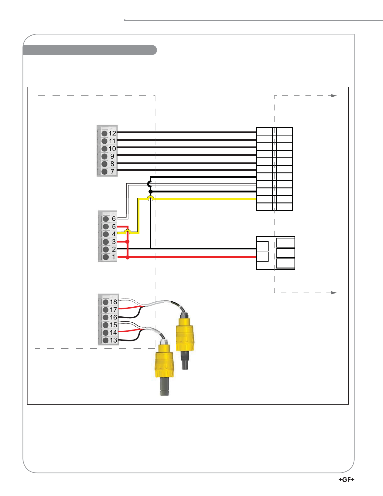
Electrical Box Wiring Schematic
Electrical Box Wiring Schematic
3-8630-3P (159 001 673) Customer Wiring
Relay 2 (N.O.)
Relay 2 (COM)
Relay 2 (N.C.)
Relay 1 (N.O.)
Relay 1 (COM)
Relay 1 (N.C.)
Loop 2 -
Loop 2
System Power Loop 1 -
System Power Loop 1
AUX Power -
AUX Power
Transmitter
Terminals
+
+
+
Black
Black
Black
Black
Black
Black
Black
White
Black
Yellow
Black
Red
Terminal
Block
10
9
8
7
6
5
4
3
2
1
GND
– V
+V
10
9
8
7
6
5
4
3
2
1
GND
GND
N
L
NO
COM RELAY 2
NC
NO
COM RELAY 1
NC
– LOOP 2
+ LOOP 2
– LOOP 1
+ LOOP 1
EARTH GROUND
Ground
Digital (S
Ground
Digital (S
3
V+
3
V+
Power Supply
24 VDC
White
L)
L)
Red
Black
White
Red
Black
Signet pH Sensor Electronics
3-2750-7 (159 001 671)
Signet Chlorine Sensor Electronics
3-2650-7 (159 001 670)
10
463X Chlorine System Manual
Page 11
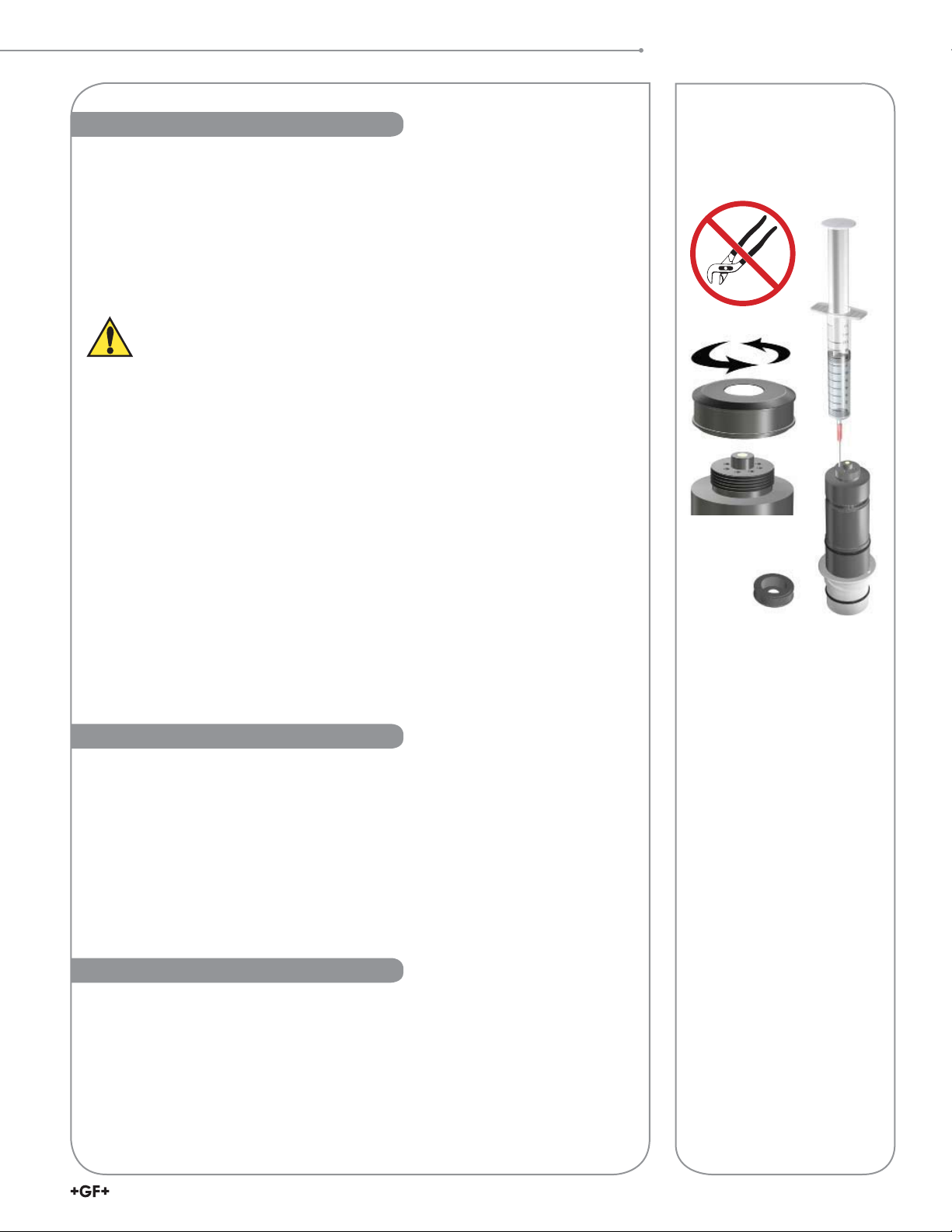
Chlorine Sensor Preparation
2630 Free Chlorine Electrode
2632 Chlorine Dioxide Electrode
• Chlorine sensors are shipped without internal electrolyte solution.
• Prior to installation and supplying power, Chlorine sensors must be lled with the
appropriate internal electrolyte solution.
• Verify the correct electrolyte solution is utilized with the corresponding sensor.
• Free Chlorine and Chlorine Dioxide sensor require different electrolyte solutions.
Avoid skin or eye contact with electrolyte solution.
Wear rubber gloves and goggles.
* Material Safety Data Sheets (MSDS) are available online at www.gfsignet.com.
Initial Fill Procedure:
When adding electrolyte, be prepared for an accidental spill.
Working near a sink is recommended.
1. Remove the protective bottle from the end of the electrode
2. Remove the membrane cap from the front of the sensor.
Note: When new sensors are shipped, the membrane cap is not tightened to the sensor
3. Fill supplied syringe with electrolyte solution.
Additional caution should be taken when handling Chlorine Dioxide electrolyte solution.
4. Place the electrode on a level surface.
5. Insert syringe needle fully into one of the eight electrode holes while injecting with
electrolyte solution. Slowly injecting the electrolyte solution into the sensor to avoid
introducing air bubbles. The electrode holds approximately 14 milliliters of solution.
Slowly ll until solution begins to ow out of holes. Do not allow the solution to run
down the electrode and wet the electrical contacts in the DryLoc connector.
6. Slowly screw on the membrane cap nger tight. Do not use tools. To avoid damage
and contamination, do not touch the white membrane surface on the membrane cap.
Sensor Preparation
CAUTION:
DO NOT touch the gold tip or
the membrane of the sensor.
Chlorine Sensor Calibration
A new chlorine electrode or one that has had the membrane cap changed must be
calibrated. See page 24, 8630 Transmitter information on calibration of the chlorine
sensor. A diethyl-p-phenylenediamine (DPD) colorimeter test kit (not included) is required
for sensor calibration. A sample is taken and analyzed with the DPD test kit, then this
value is entered into the Signet 8630 transmitter.
• Calibrate after a membrane cap change (requires 4 hour stabilization time).
• Calibrate after the internal electrolyte is replaced (requires 2 hour stabilization time).
• Check calibration one day after sensor is placed in service.
• Check calibration weekly to monthly depending on process requirements.
Chlorine Sensor Maintenance
The sensor membrane and internal electrolyte solution must be replaced over the life
of the electrode. To maintain accurate chlorine measurements, GF Signet recommends
that the internal electrolyte be replaced every 3 to 6 months, or when Chlorine readings
drift low and/or cannot maintain a calibration longer than 5 days. Actual interval between
maintenance of the sensor will be dependent on the actual applications, chlorine level and
contaminates in the water. See Appendix page 36; Maintenance and Storage.
Keep spare membrane caps available. Membrane caps carry no warranty.
NOTE: Inspect and change the
membrane cap if damaged.
See page 36, Maintenance, for
cleaning procedure.
11463X Chlorine System Manual
Page 12
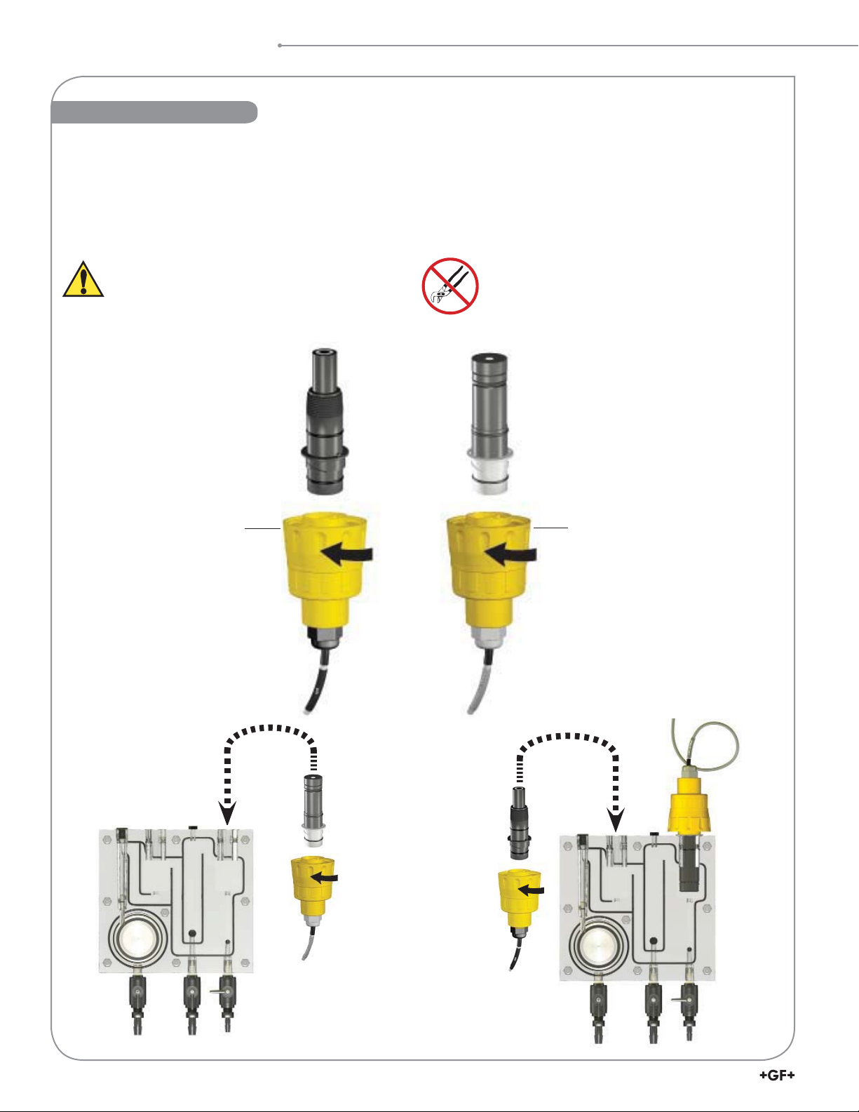
Sensor Installation
Sensor Installation
• Remove sensor access plugs from the ow cell (pg. 4, Figure 1).
Note: Chlorine Sensor Preparation must be completed prior to installation, see page 11.
• Holding the 3-2750-7 (159 001 671) or 3-2650-7 (159 001 670) electronics inverted, open the DryLoc
turning the upper locking ring ¼-turn counter-clockwise.
• Insert the electrode facing up. Turn the locking ring ¼-turn clockwise to lock the electronics in place.
• The mechanism will “click” when it is locked.
• Install the complete assembly into the ow cell and ensure the key on the electrode aligns with the key slot on the ow cell.
Avoid skin or eye contact with electrolyte solution.
Wear rubber gloves and goggles.
Material Safety Data Sheets (MSDS) are available
online at www.gfsignet.com.
Do Not Use Lubricant or Sealing Tape on Threads.
Do Not Overtighten. Do Not Use Tools.
Do Not Drop or Strike the Membrane.
DryLoc® Connection to Sensor Electronics
®
connector by
3-2724-00
(159 001 545)
pH electrode
Locking Ring
3-2750-7
(159 001 671)
pH electronics
Lubricate O-rings with
a non-petroleum
based, viscous
lubricant (grease)
compatible with the
system.
Signet 3-2630-X
Signet 3-2632
Chlorine Electrode
3-2630-X
FCL electrode
3-2632
ClO2 electrode
Locking Ring
LockLock
3-2650-7
(159 001 670)
Amperometric Electronics
12
Signet 3-2724-00
(159 001 545)
Flat pH Electrode
Signet 3-2650-7
Electronics
Signet 3-2750-7
pH Electronics
463X Chlorine System Manual
Page 13
Tubing Connections
Water Flow
Use suitable 9.5 mm (3/8 in) ID tubing that is rated for your
inlet pressure. Use hose clamps.
Inlet Quick Release Connection
Press down gray plunger to release. Water ow is
automatically shut off when disconnected.
Valve position for start up and normal use.
Note: Turn off inlet valve rst when stopping water ow.
• The drain tube must be positioned lower than the in uent
water source to allow proper ow through the ow cell.
The ow cell must drain by gravity, not system pressure.
• When testing, allow the sample to ow for a few seconds
before collection.
Inlet
Drain
(to atmosphere)
Sampling port
( ow off)
Water Flow
Flow Rate
The ow rate is in the proper range when the oat is
between the Min. and Max. markers on the ow cell. The
ow range limits are 30.24 to 45.36 L/h (8 to 12 gal/h).
OK
For Low Flow applications ( ow less than 1 bar/15 psi), the
Flow Regulator can be removed and the ow adjusted using
the Flow Cell ball valve. (NOTE: The inlet hose barb will also
need to be changed. Contact factory for details.)
pH Cl
IN
OUT
13463X Chlorine System Manual
Page 14
8630 Chlorine Transmitter
8630 Chlorine Transmitter
The Signet 8630 ProcessPro® Chlorine Transmitter displays and transmits free chlorine or chlorine
dioxide, along with pH information when connected to Signet Amperometric Chlorine Sensors and
a Signet pH Sensor.
Features of the 8630 include:
• Displays Free Chlorine measurements from 0 to 20 ppm (parts per million) or Chlorine Dioxide
measurements from 0 to 2 ppm.
• Speci es all compatible chlorine sensors.
• Automatic pH and temperature compensation or manual pH input to calculate accurate
free chlorine measurements.
• Simple setup and easy customization with the 4-button keypad.
• Dual 4 to 20 mA outputs with two built-in SPDT mechanical relays.
• Easy viewing via the bright backlit LCD display.
CAUTION!
• Remove power to unit before wiring input or output connections.
• Follow instructions carefully to avoid personal injury or damage to the transmitter.
8630
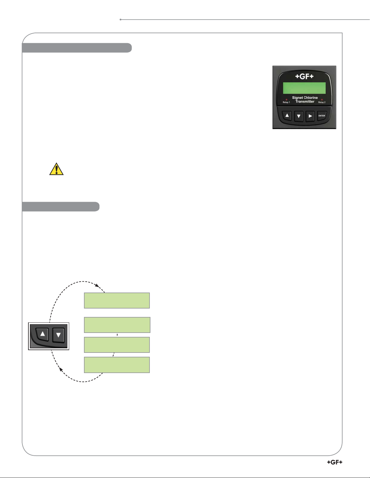
Chlorine
8630 View Mode
• The View Menu is displayed during normal operation.
• To select a VIEW display, press the or keys. The selections will scroll in a continuous loop. There are four pages to view.
• Changing the VIEW display does not interrupt system operations.
• No key code is necessary to change display selection.
• Output settings cannot be edited from the VIEW menu.
• All menus time-out after 10 minutes and return to the previous operating display.
• When editing the CALIBRATE or OPTIONS menus, the transmitter will return to the default display after 10 minutes and then
the VIEW menu in another 10 minutes if no activity occurs.
FCl: 2.67 ppm
7.10 pH 25.3 °C
The example View menus below return to the default display after 10 minutes.
Cl Raw: 103.8 nA
pH Raw: -5.9 mV
Loop 1 10.68 mA
Loop 2 8.56 mA
Last CAL:
10-18-10
View chlorine, pH and temperature values from the sensor.
FCl = free chlorine, ClO2 = chlorine dioxide.
Chlorine (nA) and pH raw (mV) signals from the sensors.
For reference only.
View of current loop 1 and loop 2 output.
View of the last calibration date. Editable in the Calibrate Menu.
14
463X Chlorine System Manual
Page 15
8630 Editing Procedure
8630 Editing Procedure
The 8630-3 (159 001 662) has two menus the user can edit: CALIBRATE and OPTIONS.
• The CALIBRATE menu allows you to calibrate and initialize sensors, de ne current loops and set relay functions.
• The OPTIONS menu allows you to set sensor type, adjust and test current loops, test relays and more.
Step 1. Press and hold the ENTER key:
• 2 seconds to select the CALIBRATE menu.
• 5 seconds to select the OPTIONS menu.
Step 2. Enter the Key Code.
The Key Code is --- keys in sequence.
• After entering the Key Code, the display will show the rst item in the selected menu.
Step 3. Scroll the menu in a loop with the or arrow keys.
Step 4. Press the key to select the menu item to be edited.
• The rst display element will begin ashing.
Step 5. Press the or keys to edit the ashing element.
• The key advances the ashing element.
Step 6. Press the ENTER key to save the new setting and return to Step 3.
Made an Error?
Press the and keys simultaneously
while any element is ashing. This will recall
the last saved value of the item being edited
and will return you to Step 3.
Press the and keys simultaneously
after saving the last setting to return to
View menu.
Finished Editing?
15463X Chlorine System Manual
Page 16

8630 Editing Procedure
Example: Calibration
Access the CALIBRATE Menu:
ENTER
ENTER
Press and hold the ENTER key for 2 seconds to access
the CALIBRATE menu.
Enter the Key Code:
The CALIBRATE and OPTIONS menus require a
password (KEY CODE). Pressing the , , , keys
in sequence unlocks the display and the rst menu item
will appear. If no key is pressed for 5 minutes while the
display is showing "Enter Key Code", it will return to the
VIEW menu.
Scroll the Menu:
Press the or keys to scroll through the Menu.
While in this mode, pressing the and keys
simultaneously will return the display to the VIEW menu.
If no key is pressed for 10 minutes, the display will
return to the VIEW menu.
Step 1.
Step 2.
Step 3.
(Hold)
ENTER
ENTER
CALIBRATE menu
OR
2s
CALIBRATE:---Enter Key Code
CALIBRATE:--Enter Key Code
CALIBRATE:-Enter Key Code
CALIBRATE:Enter Key Code
Cl Zero
Calibration: >
Cl Zero
Calibration: >
Last Cal:
09-18-09 >
OPTIONS
5s
menu
Select the item to be edited:
In this example, "Last Cal" (last calibration date) is
chosen to edit. Pressing the key selects the menu
item and enters the screen into edit mode.
Edit the ashing element:
This is the edit mode.
The or keys change the ashing element.
The key advances the ashing element in a
continuous loop. In this example, the "Last Cal" date
was changed from 09-18-09 to 10-18-09.
All output functions remain active during editing.
Only the ashing element can be edited.
Press ENTER to save the new value.
ENTER
ENTER
When you have set your desired value, pressing the
ENTER key stores the value on the screen, making it
immediately available to output functions and exits you
back to Step 3.
Step 4
Step 5.
Step 6.
Last Cal:
.
09-18-09 >
Last Cal:
09-18-09
Last Cal:
19-18-09
Last Cal:
19-18-09
Last Cal:
10-18-09
Last Cal:
Saving
Last Cal:
10-18-09
Example
ENTER
ENTER
16
463X Chlorine System Manual
Page 17

8630 Calibrate Menu
8630 Calibrate Menu
The menus below are displayed here in the order seen when scrolling down through the Calibrate Menu.
NOTE:
For greater accuracy it is recommended that the initial calibration of the system should be in the following order:
1. Temperature
2. pH electrode (if optional pH sensor is installed. If manual pH sensor is selected enter the pH value into the
option menu prior to calibrating the chlorine sensor)
3. Chlorine sensor.
• Although the Calibrate Menu can be navigated upwards or downwards, it is best to navigate downwards when editing Current
Loop and Relay settings as previous entries can in uence subsequent menus.
• Chlorine and pH calibration screens will be shown only when a valid sensor is detected.
(Hold)
ENTER
ENTER
2s
Press the or Arrow
key to scroll through the menus.
Calibrate Menus
Factory settings shown
Chlorine Units:
ppm >
Cl Zero
Calibration: >
Cl In Process
Calibration: >
Reset Cl to
Factory Cal: >
Cl Temperature
Calibration: >
NOTE: The next two pH calibration screens will be shown only when a valid pH sensor is detected.
pH Standard
Calibration: >
pH Slope
Calibration: >
This is the rst screen. Choose units of measurement: ppm or mg/l.
When > is pressed, the “live” readings are shown. The nA value is displayed, but cannot be
edited and is used for diagnostic and calibration purposes. When in Edit Mode, pressing Enter
stores the displayed value as your zero reference.
Enter process chlorine value determined from a DPD test kit here.
This menu resets Cl readings, Zero Calibration and temperature back to Factory Calibration.
WARNING! User entered Cl calibration settings will be lost.
Enter process temperature from a reference thermometer: °C or °F. Units are set up in the
Options Menu.
Set pH standard value. This applies a linear offset to the pH measurement.
Applies a slope to the pH measurement. The slope and standard value must be at least
2 pH units apart.
Press the key to enter Edit mode.
Description
Press the Enter key to save
ENTER
ENTER
your settings.
Reset pH to
Factory Cal: >
Loop 1 Source:
Chlorine >
Loop 1 Rng: ppm
0.00 5.00 >
Loop 2 Source:
pH >
Loop 2 Rng: pH
00.0 14.00 >
Reset pH standard, slope or back to Factory Calibration.
WARNING! User entered pH calibration settings will be lost.
Current Output Functions
Choose chlorine or pH for this 4 to 20 mA current loop.
Select the minimum and maximum values for the current loop output. Units are derived from
Loop 1 Source. If the Source 1 is changed, be sure to re-edit this page.
Choose pH or chlorine for this 4 to 20 mA current loop.
Select the minimum and maximum values for the current loop output. Units are derived from
Loop 2 Source. If Source 2 is changed, be sure to re-edit this page.
17463X Chlorine System Manual
Page 18

8630 Calibrate Menu
8630 Calibrate Menu - continued
Verify all relay settings if the Relay Source is changed.
Relay Functions
Relay 1 Mode:
Off >
If Low or High Mode was chosen:
Choose mode of operation: Off, Low, High, Window, or Pulse. If Off, all subsequent Relay 1
functions are inactive and not visible.
Relay 1 Source:
Chlorine >
Relay 1 Setpnt:
0.00 ppm >
Relay 1 Hys:
0.20 ppm >
Relay 1 Delay:
0.0 secs >
If Window Mode was chosen:
Relay 1 Source:
Chlorine >
Relay1 Rng: ppm
0.00 5.00 >
Relay 1 Hys:
0.20 ppm >
Relay 1 Delay:
0.0 secs >
Choose chlorine or pH for Relay 1.
In Low or Hi Mode, Relay 1 will be activated when the process reaches this value.
Units of measure re ect Relay 1 Source.
Relay 1 will be deactivated at Relay 1 Setpoint ± this hysteresis setting depending on High or
Low Setpoint selection.
Set the time delay for Relay 1 to activate after reaching the Setpoint.
Range: 0 to 6400 seconds.
Choose chlorine or pH for Relay 1.
Enter the range where Relay 1 will activate above and below this setpoint.
Relay 1 will be deactivated at Range setpoints ± this hysteresis setting.
Set time delay for Relay 1 to activate after reaching the setpoints set in Relay 1 Range.
If Pulse Mode was chosen:
Relay 1 Source:
Chlorine >
Relay1 Rng: ppm
0.00
5.00 >
Relay1 PlsRate:
120 pulses/min >
Relay 2 Mode:
Off >
If Low or High Mode was chosen:
Choose Relay 2 mode of operation: Off, Low, High, Window, or Pulse.
To disable this relay choose Off.
Relay 2 Source:
pH >
Relay 2 Setpnt:
0.00 pH >
Relay 2 Hys:
0.20 pH >
Relay 2 Delay:
0.0 secs
>
Choose chlorine or pH for Relay 1.
Enter the range where Relay 1 will activate above and below this setpoint.
Set the maximum pulse rate. Range: 1 to 400 pulses/min.
Choose pH or chlorine for Relay 2. This menu screen and all subsequent Relay 2 screens
below do not appear if Relay 2 Mode is set to Off.
In Low or High Mode, Relay 2 will be activated when the process reaches this value.
Units of measure re ect Relay 2 Source.
Relay 2 will be deactivated at Relay 2 Setpoint ± this hysteresis setting depending on High or
Low Setpoint selection.
Set the time delay for Relay 2 to activate after reaching the Setpoint.
Range: 0 to 6400 seconds.
18
463X Chlorine System Manual
Page 19

8630 Calibrate Menu - continued
If Window Mode was chosen:
8630 Calibrate Menu
Relay 2 Source:
pH >
Relay 2 Rng: ppm
0.00 5.00 >
Relay 2 Hys:
0.20 ppm >
Relay 2 Delay:
0.0 secs >
If Pulse Mode was chosen:
Relay 2 Source:
pH >
Relay2 Rng: pH
0.00 14.0 >
Relay2 PlsRate:
120 pulses/min >
Find New
Sensor(s): >
Choose pH or chlorine for Relay 2.
Enter the range where Relay 2 will activate above and below this setpoint.
This relay will be deactivated at Relay 2 Range setpoints ± this hysteresis.
Set the time delay for Relay 2 to activate after reaching the setpoints set in the
Relay 2 Range.
Choose pH or chlorine for Relay 2.
Enter the range where Relay 2 will activate above and below this setpoint.
Set the maximum pulse rate. Range: 1–400 pulses/min.
Required only when a new sensor is changed while the power is on. Choose Yes or No.
Last Cal
10-18-09 >
Edit the calibration date.
End of Calibrate Menu
19463X Chlorine System Manual
Page 20

8630 Options Menu
8630 Options Menu
The menus below are displayed here in the order seen
when scrolling down through the Calibrate Menu.
Press the or Arrow key to
scroll through the menus.
Options Display
(Factory settings shown)
Contrast:
3 >
Cl Sensor Type:
Free Cl >
pH Input
Sensor >
If Manual pH input was chosen:
Manual pH Value
7.000 pH
Adjust the LCD contrast for best viewing. A setting of 1 is lower contrast, 5 is higher.
Select the chlorine sensor: Free Cl or ClO2.
Choose Manual or Sensor. If Sensor is chosen, the pH value from the connected pH sensor will be
used. Choose Manual to enter a pH value manually when no sensor is connected or if measuring
chlorine dioxide.
Enter your pH value here if a pH sensor is not connected.
(Hold)
ENTER
ENTER
Press the key to enter Edit mode.
Description
5s
OPTIONS menu
Press the Enter key to save
ENTER
ENTER
your settings.
Temp Display:
°C >
Averaging:
Off >
Decimal:
***.** >
Loop 1 Adjust:
4.00 mA >
Loop 1 Adjust:
20.00 mA >
Loop2 Adjust:
4.00 mA >
Loop2 Adjust:
20.00 mA >
Test Loop 1:
>
Test Loop 2:
>
Choose units of °C or °F.
OFF gives the fastest response to input changes. LOW = 4.5 seconds, HIGH = 9 seconds of averaged
response. Increase averaging to steady the display.
Select the decimal point for the display. Maximum of 2 decimal places.
Adjust the minimum current output for Loop 1. The display value represents the precise
current output. Range: 3.80 mA to 5.00 mA.
Adjust maximum current output for Loop 1. Range: 19.00 mA to 21.00 mA.
Adjust the minimum current output for Loop 2. Range: 3.80 mA to 5.00 mA.
Adjust maximum current output for Loop 2. Range: 19.00 mA to 21.00 mA.
Press UP or DOWN keys to manually output any current value from 3.6 mA to 21.00 mA to test
Loop 1 output.
Press UP or DOWN keys to manually output any current value from 3.6 mA to 21.00 mA to test
Loop 2 output.
20
463X Chlorine System Manual
Page 21

8630 Options Menu - continued
8630 Options Menu
Test Relay 1:
Test Relay 2:
>
Read Sens Data:
No >
If Yes was chosen:
Cl Sensor S/N:
xxxxxxxxx
Cl Type & Range:
2630 xxx.x ppm
Zero Cal: ppm&nA
xxx.xx xxxx.x
In Proc: ppm&nA
xxx.xx xxxx.x
Temp at Cal:
xxxx.x °C
pH at Cal:
xxx.xx pH
Press UP or DOWN keys to manually toggle Relay 1 Off and On. The left LED on the front of
the transmitter con rms operation.
>
Press UP or DOWN keys to manually toggle Relay 2 Off and On. The right LED on the front of the
transmitter con rms operation.
If "YES" is selected the following (Read Only) screens will be shown.
If "NO" then this menu ends the Options Menu.
View the sensor serial number.
Identify the chlorine sensor type connected and its ppm range.
View user entered Zero Calibration data in ppm and nA.
View user In-Process Calibration value when it was entered in the Calibrate Menu.
Temperature recorded during user In-Process Calibration.
pH value recorded during user In-Process Calibration.
Temp Offset:
xxxx.x °C
Elapsed Time:
xxxxx. hrs
Low & High: °C
-xxxx.x +xxxx.x
Temperature offset calculated from user entered temperature calibration from Calibrate Menu.
Total hours of operation.
Lowest and highest temperatures the Cl sensor has been subjected to during operation.
End of Options Menu
21463X Chlorine System Manual
Page 22

pH Sensor Calibration
Chlorine Sensor Conditioning
A new chlorine sensor or one that has had the electrolyte
or membrane replaced must be conditioned to generate
stable and accurate readings. To condition a chlorine sensor,
the sensor and sensor electronics must be installed and
powered, and must also have chlorinated water ow across
the membrane.
Chlorine Sensor Conditioning
1. Turn on and adjust water ow rate. Condition a new
chlorine sensor for 4 hours. Conditioning time for a
membrane cap replacement and/or electrolyte re ll is
2 hours.
2. Keep of ine any 4 to 20 mA devices or relay actuated
output devices that connect to the transmitter.
NOTE: The membrane cap may have to be replaced when
electrolyte is changed. Replace membrane if damaged.
The electrolyte should be replaced every 3 to 6 months.
pH Sensor Calibration
If a pH sensor is part of the system, use the Calibration
Kit 3-2700.395 (159 001 605) prior to initially installing
the sensor and during its normal lifetime. If a pH sensor is
not available but pH determination is necessary, measure
process pH with a separate test and enter the value in the
Options Menu.
NOTE: Temperature must be calibrated before calibrating the
pH sensor. See Chlorine Sensor section.
Refer to your pH sensor manual.
The pH sensor needs to be calibrated against two different pH
buffer references to calibrate the offset (standard) and slope.
Electrode offset is any deviation from 0 mV in a pH 7 buffer at
25 °C. Slope is the ratio of mV to pH units.
• Always keep any output devices of ine when calibrating.
Set pH Offset (Standard)
The transmitter must be powered on and the pH sensor must
be connected.
1. Turn off the water ow through the system, then remove
the pH sensor from its ow cell.
2. Using pH buffer 7.0, place enough pH buffers into
clean calibration cups, supplied with the pH calibration
kit 3-2700.395 (159 001 605), to cover the tip of the
electrode.
3. Pour distilled water in another clean cup for rinsing the
electrode between buffers.
4. Rinse probe, place the pH sensor in the pH 7.0 buffer
and allow the mV reading to stabilize.
Example: Set pH Standard to 7.00.
5. Go to the Calibrate Menu.
6. Scroll down 5 menus to the pH Standard menu.
7. Press to enter Edit Mode.
8. Enter the pH value of the buffer that the electrode is
placed in; 7.00 in this case.
9. Press the Enter button to save the setting.
10. Exit to the View Menu.
EXAMPLE
EXAMPLE
Step 4
FCl: 2.67 ppm
View Menu
7.11 pH 25.3°C
(Hold)
ENTER
ENTER
5
6
7
8
pH buffer value
entered here
NOTE: The pH sensor will not calibrate when the mV value
exceeds 50 mV from the original new electrode speci cation.
Electrode: pH 4.01 = + 177 mV.
pH Standard
Calibration: >
pH Standard Cal:
07.00 pH/ 0 mV
ENTER
ENTER
2s
5X
Calibrate Menu
22
463X Chlorine System Manual
Page 23

Set pH Slope
1. Remove the pH sensor from the rst buffer solution and
rinse it in distilled water.
2. Place the pH sensor in a different buffer solution
(example: pH 4.01). The pH standard and slope must be
at least 2 pH units apart.
3. Note the pH and mV readings on the View Menu and
allow it to stabilize.
Example: Set pH slope to 4.01.
EXAMPLE
4. Scroll down 1 menu to the pH Slope menu.
5. Press to enter Edit Mode.
6. Enter the pH value of the buffer that the electrode is
placed in; 4.01 in this case.
7. Press the Enter button to save the settings.
8. Exit to the View Menu.
9. Replace the pH sensor back into its ow cell.
10. Turn on the water ow.
The pH sensor calibration is complete.
EXAMPLE
4
5
6
pH buffer value
entered here
pH Sensor Calibration
pH Standard Cal:
07.00 pH/ 0 mV
pH Slope
Calibration:
pH Slope Cal:
04.01 pH/ +177 mV
ENTER
ENTER
View Menu
Calibrate Menu
>
Set Manual pH Compensation
If the pH of the application is stable, then the pH of the
application can be entered manually and will be used to
calculate the free chlorine measurements.
NOTE: Chlorine dioxide does not require pH compensation.
Example: Change the pH input from Sensor to Manual
and enter a pH value of 7.22.
1. Go to the Options Menu.
2. Scroll down 2 menus to the pH Input menu.
3. Press to enter Edit Mode.
4. Choose Manual and press Enter.
5. Scroll down 1 menu to the Manual pH Value menu.
6. Press to enter Edit Mode.
7. Enter your new process pH value: 7.22.
8. Press the Enter button to save the setting.
9. Exit to the View Menu.
EXAMPLE
EXAMPLE
pH Input
Sensor >
pH Input
4
Sensor Manual
ENTER
ENTER
pH Input
5
Manual
Manual pH Value
7
7.220 pH
ENTER
ENTER
Options MenuStep 2
Manual chosen
>
New pH value entered
23463X Chlorine System Manual
Page 24

Chlorine Sensor Calibration
Chlorine Sensor Calibration
Chlorine sensors need to be calibrated for accuracy. After the
4 hour conditioning period, Temperature Calibration,
Zero Point Calibration and In-Process Calibration needs to
be performed. Any 4 to 20 mA or relay output devices should
be of ine.
Chlorine Sensor Temperature Calibration
The temperature element inside the chlorine sensor needs
to be calibrated. Use a reference thermometer to verify the
actual temperature of the sample. This value is then entered
in Step 4 to calibrate the system.
Tip: Remove the pH electrode from the ow cell and insert
the reference thermometer. If no pH sensor is being used,
remove the cell plug to insert the thermometer. Replace the
plug after calibration.
Example: Set the calibrated temperature to 25.3 ºC.
1. Go to the Calibrate Menu.
2. Scroll down 3 menus to the Cl Temperature menu.
3. Press to enter Edit Mode.
4. Enter the temperature reading. Example: 25.3.
5. Press the Enter button to save the setting.
6. Exit to the View Menu.
Zero Point Calibration
The chlorine sensor needs to be calibrated against two
chlorine references: zero chlorine and the process chlorine.
Typically the zero point calibration is very stable. Calibration
must be done with every new sensor and any time a
membrane cap is replaced.
1. Keep of ine any 4 to 20 mA devices or relay actuated
output devices that connect to the transmitter.
2. Turn off the water ow and remove the powered chlorine
sensor with the electronics still attached.
3. Place the sensor tip in distilled water.
4. Wait until the reading stabilizes, then save the
calibration. Stirring the sensor in water is not necessary,
but allows the signal to stabilize faster.
Example: Set the Zero Point Calibration at 1.0 nA.
5. Go to the Calibrate Menu.
6. Scroll down one menu to the Cl Zero menu.
7. Press to enter Edit Mode. The live sensor readings in
ppm and nA will be ashing. These readings cannot be
modi ed, but can only be saved as displayed.
8. Press the Enter button at the lowest reading to save the
setting or press to escape without changes.
9. Exit to the View Menu.
10. After Zero Point Calibration is complete, replace the
sensor back into the ow cell and turn the water ow
back on.
11. Wait until the chlorine readings stabilize once again, then
perform a chlorine In-Process Calibration.
EXAMPLE
EXAMPLE
EXAMPLE
Step 2
New temp. value
Cl Temperature
Calibration: >
Cl Temp: Cal
4
+025.3 °C
ENTER
ENTER
EXAMPLE
Step 6
The signal level during a Zero Point
Calibration must be at least 1 nA lower
than the In-Process Calibration point.
Cl Zero:
Calibration
Zero Cal: ppm&nA
8
0.20 / 001.0
ENTER
ENTER
>
Lowest value noted for
Zero Cal.
Calibrate Menu
Calibrate Menu
24
463X Chlorine System Manual
Page 25

In-Process Calibration
A diethyl-p-phenylenediamine (DPD) colorimeter test kit (not
included) is required for sensor calibration. A sample is taken
and analyzed with the DPD test kit, then this value is entered
into the Signet 8630 transmitter.
Chlorine Sensor Calibration
1. Take a water sample from the Sampling Port (after
purging it) from a stabilized and running system.
2. Use this sample to measure the chlorine content with
a colorimetric DPD test kit (not included). Refer to the
DPD kit instructions on how to perform this test.
NOTE: For greater accuracy, it is recommended
that the DPD test be repeated three times and
the results averaged together.
3. Record the test results.
Example: Set the Chlorine In-Process to 2.67 ppm.
4. Go to the Calibrate Menu.
5. Scroll down 2 menus to the Cl In-Process menu.
6. Press to enter Edit Mode.
7. Enter the chlorine reading determined from the DPD test
into the edit screen: 2.67 ppm. The Cl ppm is editable
and must be at least 0.2 ppm.
8. Press the Enter button to save the setting.
9. Exit to the View Menu.
Calibration is complete for the chlorine sensor.
EXAMPLE
EXAMPLE
Step 5
DPD Cl ppm value
entered here.
The signal level during an In-Process
Calibration must be at least 1 nA higher
than the previous Zero Calibration point.
Cl In Process
Calibration: >
In Proc: ppm&nA
7
2.67 / 103.8
ENTER
ENTER
Calibrate Menu
Output Settings - Loops and Relays
Con gure the current loop and relay functions if applicable.
NOTE: The current and relay outputs can be tested in the
Options Menu.
Current Loop Settings
Current outputs are passive outputs that can be spanned in
the forward and reverse direction. Example: 0 to 5 or 5 to 0.
Example: Set a current loop source as chlorine and the
operational range to 0 to 5 ppm.
1. Go to the Calibrate Menu.
2. Scroll down to the Loop 1 Source menu.
3. Press to enter Edit Mode.
4. Choose either the chlorine or pH sensor as the source
that will control this loop: Chlorine.
5. Press the Enter button to save the setting.
6. Scroll down 1 menu to the Loop 1 Rng menu.
7. Press to enter Edit Mode.
8. Select the minimum and maximum process values for
the current loop output: 0 to 5 ppm.
9. Press the Enter button to save the setting.
10. Exit to the View Menu.
EXAMPLE
NOTE:
When integrated into the 463X Chlorine Panel Assembly,
the loop outputs are wired into Active outputs via the
terminal strip found inside the 463X enclosure.
EXAMPLE
Step 2
Loop 1 Source:
Chlorine >
Set and save
Loop 1 Rng: ppm
6
0.00 5.00 >
Set and save
Calibrate Menu
25463X Chlorine System Manual
Page 26

1 4 mg/l
Output (pulses per minute)
Ending
Point
Input (mg/l)
Starting
Point
0
20
40
60
80
100
Pulse
Hysteresis
Time
Low Setpoint
Process
Relay energized
Relay de-energized
Hysteresis
Time
High Setpoint
Process
Time
High Limit
Hysteresis
Hysteresis
Low Limit
Process
Window
Output Settings
Mechanical Relay Functions
The 8630 relays are selectable and con gurable and can
be used as switches that respond when the process value
moves above or below a user de ned setpoint. They can
be used for Low Alarm, High Alarm or Proportional Pulse
triggering related to the process value. Relay functions,
hysteresis and time delay settings are set up in the
CALIBRATE menu and can be tested in the OPTIONS menu.
Low Setpoint:
Relay is energized when the measured value is less than
the setpoint.
High Setpoint:
Relay is activated when the measured value is higher than
the setpoint.
Window:
Relay is off within the window of two setpoints minus the
hysteresis. Relay is activated when the value is higher or
lower than the high and low setpoint.
Pulse-frequency Operation:
The transmitter can output a pulse at the rate de ned by
the settings in the CALIBRATE menu and the sensor input.
The maximum pulse square wave output from the relays is
400 pulses per minute. Example usage would be to control
solenoid operated dosing pumps.
Example: As the process value drops below the setpoint
(4 mg/l) the output will start pulsing in relation to the process
value, the maximum pulse endpoint and the programmed
pulses/minute. The pulse rate will increase as the process
value decreases and approaches the programmed endpoint.
This functionality can be used to precisely control the
process.
• The output will be 0 pulses/minute when the input value is
greater than 4 mg/l.
• The output will be 35 pulses/minute when the input value is
3 mg/l.
• The output will be 100 pulses/minute when the input value
is 1 or less.
The starting point, endpoint and maximum pulse rate are
select able in the CALIBRATE menu.
26
463X Chlorine System Manual
Page 27

Relay Settings
Relay energized
Relay de-energized
Output Settings
Example: Set a relay to energize at a low setpoint of
1.0 ppm with a time delay of 15 seconds and de-energize
at 1.30 ppm.
• Once a setting is saved it immediately becomes
active.
1. Go to the Calibrate Menu.
2. Scroll down to the Relay 1 Mode menu.
3. Press to enter Edit Mode.
4. Scroll down and choose Low.
5. Press Enter.
6. Scroll down to the Relay 1 Source menu. The default
is Free Chlorine.
7. Scroll down to the Relay 1 Setpnt menu.
8. Press to enter Edit Mode.
9. Set the ppm value to trigger the relay: 1.00 ppm.
10. Press Enter.
11. Scroll down to the Relay 1 Hys menu.
12. Press to enter Edit Mode.
13. Set the hysteresis (dead zone) for this relay. This affects
the turn off only: 0.3 ppm.
14. Press Enter.
15. Scroll down to the Relay 1 Delay menu.
16. Press to enter Edit Mode.
17. Set the turn-on delay in seconds for the relay: 15 secs.
18. Press Enter.
19. Exit to View Mode.
EXAMPLE
1.30
1.00
Cl ppm
Low
Setpoint
EXAMPLE
Step 4
Relay 1 Mode:
Low >
Relay 1 Source:
6
Chlorine >
Relay 1 Setpnt:
9
1.00 ppm >
Time
Time Delay
Calibrate Menu
Set and save
Set and save
Set and save
• Relay function can be tested in the Options Menu.
13
17
Relay 1 Hys:
0.30 ppm >
Set and save
Relay 1 Delay:
15.0 secs >
Set and save
27463X Chlorine System Manual
Page 28

2650-7 and 2750-7 Electronics
2650-7 Amperometric and 2750-7 pH DryLoc® Electronics
• The Signet 2650-7 Amperometric Electronics provide the polarization voltage and signal conditioning required by the Signet
2630-X and 2632-X Sensors.
• The Signet 2750-7 pH Electronics conditions and ampli es the output from the Signet 2724-00 pH Electrode.
• Both units output a Digital (S3L) signal to the Signet 8630 Chlorine Transmitter.
CAUTION!
• Remove power before wiring.
• Follow instructions carefully to avoid personal injury or
damage to the electronics.
Wiring to the Signet 8630 Chlorine Transmitter
The electronics are pre-wired from the factory to the transmitter. Refer to the following
schematics when replacing the electronics.
White
Red
Black
Shield
Signal Ground
Digital (S
3
L) data
+5 VDC
18
17
16
Gnd
I/O
V
+
N/C
pH
Signet 3-2750-7
(159 001 671)
White
Red
Black
Shield
Signal Ground
Digital (S
3
L) data
+5 VDC
15
14
13
Gnd
I/O
V
+
N/C
Chlorine
Signet 3-2650-7
(159 001 670)
8630
Chlorine
8630
Chlorine
• Refer to the wiring diagram above to connect the 2650 cable to the terminals on the 8630 Chlorine Transmitter.
• For calibration and con guration please refer to the 8630 Calibrate Menu discussions above.
28
463X Chlorine System Manual
Page 29

Chlorine Electrodes
Chlorine Electrode Overview
These electrodes require the Signet 2650 Amperometric Electronics module to communicate with the Signet 8630-3P
Chlorine Transmitter.
Electrode Range: The electrodes must match the type and range of chlorine concentration to be measured.
Flow Rate: The electrodes must have a stable and constant ow of water past its membrane for accurate measurement.
When the sensor is installed in the Flow Cell Block 3-4630.392 (159 001 690), the ow rate range is controlled by the internal
ow regulator and the ow rate is reduced to 30.24 to 45.36 LPH (8 to 12 US gph).
Sensor Conditioning: A new chlorine electrode requires conditioning of up to 4 hours with the electrode powered on and
chlorinated water owing across the membrane to generate a stable reading. Subsequent start-ups can require an electrode
conditioning of up to 2 hours.
The electrodes should not be used in water containing
surfactants, oils, organic chlorine or stabilizers such as
cyanuric acid.
The maximum allowable operating pressure must be
less than 1 bar (15 psi). Higher pressures will damage
the electrodes.
CAUTION!
1 Follow instructions carefully to avoid personal injury or damage to electrode.
2. Prior to installation or removal:
a. Disconnect ow through system.
b. Drain below sensor level.
3. Con rm chemical compatibility before use.
4. Do not alter product construction.
2630 Amperometric Chlorine Electrodes
The Signet 3-2630 Amperometric Chlorine Electrodes are designed to measure
free chlorine in ranges of 0 to 2 ppm, 0 to 5 ppm or 0 to 20 ppm.
Mfr. Part No. Code Chlorine Range Chlorine Type
3-2630-1 159 001 746 0 to 2 ppm (mg/L)
3-2630-2 159 001 662 0 to 5 ppm (mg/L) Free chlorine
3-2630-3 159 001 747 0 to 20 ppm (mg/L) Free chlorine
Free chlorine
Lubricate O-rings
with a non-petroleum
based, viscous lubricant
(grease) compatible with
the system.
2632 Amperometric Chlorine Dioxide Electrodes
The Signet 2632 Amperometric Chlorine Dioxide Electrode is designed to measure
chlorine dioxide (ClO
The Signet 2632 Amperometric Chlorine Dioxide Electrode has an integrated
temperature element for automatic temperature compensation.
Mfr. Part No. Code Chlorine Range Chlorine Type
3-2632-1 159 001 767 0 to 2 ppm (mg/L)
) in a range of 0 to 2 ppm.
2
Chlorine Dioxide
Lubricate O-rings
with a non-petroleum
based, viscous lubricant
(grease) compatible with
the system.
29463X Chlorine System Manual
Page 30

Chlorine Electrodes
pH Compensation for Free Chlorine
Amperometric free chlorine sensors measure only
hypochlorous acid. As noted in the text above and in Figure
1, the ratio of hypochlorous acid and hypochlorite is pH
dependent. In many applications the process pH is relatively
stable and no correction is needed. However, where the pH
of the water changes signi cantly, accurate free chlorine
measurement requires pH compensation. With the addition
of a pH sensor, the Signet 8630 transmitter will automatically
compensate the free chlorine reading for changes
in pH.
Automatic pH Compensation and Free Chlorine
In many applications, the process pH does not signi cantly
uctuate and only a free chlorine sensor and instrument is
necessary for accurate chlorine measurement. It is when
the pH varies that free chlorine concentration can not
accurately be determined without the use of automatic pH
compensation.
The addition of the Signet 3-2724-00 (159 001 545) pH
electrode along with its 3-2750-7 (159 001 671) preampli er
to the system makes pH compensation extremely easy and
automatic even with wide uctuations or high pH.
See Figure 2 for pH variation recommendations.
Example:
If the pH nominal value is 7.5 and the pH variation is ± 0.2
then automatic pH compensation is recommended.
If the pH nominal value is 7.0 and the pH variation is ± 0.2
then automatic pH compensation is not required.
100
90
80
70
60
50
40
30
% free chlorine
20
10
0
5.0 5.5 6.0 6.5 7.0 7.5 8.0 8.5 9.0 9.5 10.0
HOCl
OClˉ
pH at 25 °C
Figure 1
±0.3
±0.2
Calibration
A new chlorine electrode or one that has had the membrane
cap changed must be calibrated. See page 24, 8630
Transmitter information on calibration of the chlorine sensor.
A diethyl-p-phenylenediamine (DPD) colorimeter test kit (not
included) is required for sensor calibration. A sample is taken
and analyzed with the DPD test kit, then this value is entered
into the Signet 8630 transmitter.
• Calibrate after a membrane cap change
(requires 4 hour stabilization time).
• Calibrate after the internal electrolyte is replaced
(requires 2 hour stabilization time).
• Check calibration one day after sensor is placed in service.
• Check calibration weekly to monthly depending on
process requirements.
Maintenance
The sensor membrane and internal electrolyte solution
must be replaced over the life of the electrode. To maintain
accurate chlorine measurements, GF Signet recommends
that the internal electrolyte be replaced every 3 to 6 months,
or when Chlorine readings drift low and/or cannot maintain
a calibration longer than 5 days. Actual interval between
maintenance of the sensor will be dependent on the actual
applications, chlorine level and contaminates in the water.
See Appendix page 36; Maintenance and Storage.
Keep spare membrane caps available.
Membrane caps carry no warranty.
pH variation
±0.1
0
6.5 7.0 7.5 8.0 8.5 9.0
Sample pH
Automatic pH compensation recommended
=
in ranges within shaded area
Figure 2
NOTE: Inspect and change the membrane cap if damaged.
See page 36, Maintenance, for cleaning procedure.
30
463X Chlorine System Manual
Page 31

2724 pH Electrode
K5
2724 DryLoc pH Electrode
CAUTION!
1. Use appropriate eye, face, hand, body and/or respiratory protection when using chemicals or solvents.
2. Prior to installation or removal:
a. Depressurize and vent system.
b. Drain below sensor level.
3. Con rm chemical compatibility before use.
4. Do not alter product construction.
Lubricate O-rings
with a non-petroleum
based, viscous lubricant
WARNING: 3-2724-00 (159 001 545) is the only recommended
electrode to be used in the Chlorine Analyzer System.
Electrode Date Code
The electrode date code indicates the manufacturing date of the electrode. Electrodes should be put into service as
soon as possible and should not remain in the box for more than two years. Over time, the storage solution (found in
the "boot" covering the electrode tip) will evaporate or leak, allowing the delicate sensing tip and reference junction dry.
(grease) compatible with
the system.
To rehydrate a dry electrode, soak it in pH 4 buffer for 24 to 48 hours. Electrodes more than 2 years old may still be
functional, but will take longer to rehydrate. Restoration may not be effective for severely dehydrated electrodes.
First Digit = Month
N = January
M = February
L = March
K = April
J = May
H = June
G = July
F = August
E = September
D = October
C = November
B = December
Removing the electrode from In-line installations
The use of this product assumes that operators are trained and are familiar with this type of device.
They should be knowledgeable of the potential risks associated with pressurized piping systems.
Operators MUST follow all necessary safety procedures.
K5
Example: K5 = manufactured in April 2010
Second Digit = Year
5 = 2010
6 = 2011
7 = 2012
8 = 2013
9 = 2014
0 = 2015
1 = 2016
2 = 2017
3 = 2018
4 = 2019
In-line removal Instructions:
1. Depressurize and vent the piping system.
2. Drain the system to below sensor level.
3. Wear safety goggles or face shield during removal.
Use all appropriate eye, face, hand, body and/or respiratory protection when working with chemicals or solvents.
4. Place a Lockout tag on the pipe when the sensor is removed for maintenance to prevent accidental opening and
exposure to potentially hazardous chemicals.
31463X Chlorine System Manual
Page 32

2724 pH Electrode
Calibration
pH Calibration Procedure
1. Rinse the sensor off in the rinse water cup. Gently pat dry with a soft, dry cloth or tissue. Warning: Do not let the rinse
water drip into the buffer solution; this will dilute the solution and may change the buffer values.
2. Place the pH sensor in the rst buffer solution (pH 7). Wait until the output from the sensor is stable on the instrument display.
3. Follow the instrument’s instructions regarding buffer recognition.
4. Rinse the sensor with water. Warning: Do not let the rinse water drip into the buffer solution; this will dilute the
solution and may change the buffer values.
5. Dry the sensor gently by patting it with a dry, clean cloth or tissue.
6. Place the sensor in a cup containing the second buffer solution (pH 4 or pH 10). The second solution used will depend on
the typical pH value of the application.
• If the process value is below pH 7, then use a pH 4 buffer solution.
• pH 10 buffer solution is used when the typical process value is above 7 pH; however, pH 4 buffer is suf cient if pH 10
buffer is not available.
7. Wait until the output from the sensor is stable.
8. Follow the instructions in the instrument manual regarding buffer recognition.
9. Rinse the sensor with water. Warning: Do not let the rinse water drip into the buffer solution; this will dilute the
solution and may change the buffer values.
10. Dry the sensor gently by patting it with a dry, clean cloth or tissue.
11. If the calibration was successful, put the sensor back on-line. If it was not successful, clean the sensor and recalibrate.
If the sensor cannot be calibrated, the electrode may need to be replaced.
Calibration Tips
1. The pH buffer solutions can be used for calibrating more than one sensor within a day. However, the solutions must remain
free of debris and must not be diluted by rinse water from previous calibrations.
Note: Use fresh buffer solutions for best results.
2. Tap or deionized water may be used to rinse the electrodes between each buffer solution.
3. Calibration solutions change value with varying temperature. Allow both the sensor and buffers to equalize with the ambient
temperature. Sensors will not calibrate properly if the sensor is not at ambient temperature. Take note of all temperature
variations of the sensors and the calibration solutions.
4. Do not pour used buffer solutions back into the bottle; dilute with plenty of water and ush them down the drain.
5. Store electrodes in pH 4 buffer when not in use.
6. Calibrate sensors on a regular basis.
7. If the pH sensor does not calibrate within acceptable limits, clean the electrode and calibrate again. If the sensor continues
to calibrate outside of acceptable limits, the electrode is spent and must be discarded.
8. Acceptable pH ranges during calibration are as follows:
pH 7: High: 7.8 pH = -50 mV; Low: 6.2 pH = 50 mV
pH 4: High: 4.8 pH = 227 mV; Low: 3.2 pH = 127 mV
pH 10: High: 10.8 pH = -227 mV; Low: 9.2 pH = -127 mV
Electrochemical pH vs. mV Ratio
• The mV output from the electrode is created by the interaction of the
electrode and the uid. The electrode contains a gel that depletes
over time, so the instrument must be readjusted periodically to
maintain system accuracy. The need for recalibration varies with each
application, but the life of the electrode is usually consistent.
• Keep a maintenance log to establish a depletion trend in new systems.
• The mV calibration is a two-point procedure. Signet offers pH buffer
solutions prepared speci cally for this purpose.
• pH buffer solutions can be used for calibrating more than one sensor
within a day provided that the solutions are protected from debris and
are not diluted by rinse water from the calibration procedure.
• Use clean water to rinse buffer solutions from the electrode.
• Dispose of all buffer solutions at the end of the day.
• If the pH sensor will not calibrate within acceptable limits, clean the
electrode and recalibrate. If the calibration results remain outside of
acceptable limits, the sensor is depleted and must be discarded.
• Follow the guidelines of local waste disposal regulations when
discarding buffer solutions and spent electrodes.
Electrode slope is the ratio of mV to pH units.
At 25 °C the theoretical slope is 59.16 mV per pH.
Theoretical mV Values @ 25 °C
pH mV
2 +295.8 mV
3 +236.64 mV
4 +177.48 mV
5 +118.32 mV
6 +59.16 mV
7 0 mV
8 -59.16 mV
9 -118.32 mV
10 -177.48 mV
11 -236.64 mV
12 -295.8 mV
32
463X Chlorine System Manual
Page 33

Appendix
Maintenance - 463X Chlorine Analyzer Flow Cell
Sensor Removal
CAUTION: Over time, a sensor can get tight in the ow cell tting. When removing the sensor, avoid
hitting the sensor electronics on the bottom of the wiring enclosure if the sensor suddenly releases.
Take care not to damage the components.
While holding the ow cell, grasp the yellow electronics as a whole unit and
carefully pull upwards, gently rocking back and forth if necessary. Once the
sensor is loose, disengage the electronics, then remove the sensor.
TIP: A tool can be used to carefully pry the sensor electronics up and out if it is
dif cult to remove.
Under certain conditions, a dirty ow cell and lter can create a chlorine demand
which could lower the chlorine concentration in the water owing past the
chlorine sensor. It is recommended to clean the lter and ow cell on a regular
basis. The frequency of necessary cleaning will depend on the application in
which the system is being used and the level of accuracy required.
Cleaning
Appendix
Figure 1
Service the ow cell on a clean, dirt free surface
to avoid scratches or damage to the ow cell.
Step 1. Keep the system powered on.
Step 2. Disable the relays and any output loops.
Step 3. Turn off the water ow.
Step 4. Remove the sensors from the ow cell. NOTE: It is not
necessary to remove the electronics from the sensor.
Step 5. Install the vinyl caps on to the sensor tips or place the tips of
the removed sensors in a cup of sample water for temporary
storage while cleaning the ow cell.
Keep the sensor tips wet and the sensors energized.
Step 6. Remove the ow cell from the panel by removing the
knurled nuts (Figure 1).
Step 7. Remove the remaining hardware from the ow cell.
(Figure 2).
NOTE: It is recommended that an anti-seizing compound appropriate for the
application be used during the reassembling of the fl ow cell.
• Wash the surfaces with plain or soapy water only.
• Use gentle, liquid dishwashing soap if necessary.
• DO NOT USE commercial glass cleaning uids.
• Use a soft, lint-free cloth.
Servicing the Flow Regulator and Filter
WARNING: Do not disassemble the ow regulator.
There are no user serviceable parts inside.
Figure 2
Remove lter
screen to clean.
If the lter is not
desired, it may
be removed from
the system.
If your inlet pressure is less than 1 bar (15 psi), remove
the ow regulator and quick disconnect inlet connector.
Flow Regulator
33463X Chlorine System Manual
Page 34

Appendix
O-Ring Installation
CAUTION! The 3-4630.390 (159 001 688) O-ring kit
comes complete with two O-rings (5 and 6) and a
single cord of material that must be cut and tted
into the O-ring groove of the ow cell (1 and 4).
1
• The sealing of the ow cell is accomplished by four cut O-ring segments
and two round O-rings sealing the ow regulator. Refer to the illustration
below for special O-ring tting instructions. Butt all O-ring joints together
so there is no gap.
• Remove the O-rings during ow cell disassembly. Both the O-rings and all
sealing grooves should be examined for cleanliness.
• Wipe all surfaces carefully with a soft, lint-free cloth to ensure good sealing.
• The cross section of the O-rings should be round and smooth. If they are
attened, their ability to seal is reduced.
• Do not use liquid or paste sealant.
Do not scratch the sealing surfaces of the ow cell block.
Scratches to the sealing surfaces can cause irreparable leaks.
Fit all O-ring joints so there is no gap in nal assembly.
Butt ends together
2
Individual O-rings shown.
Butt all segment joints together in nal assembly.
New O-ring
cross section
Old attened O-ring
cross section
(Replace)
Fit ush with no gap
Straight cut
3
4
5
6
34
Angle cut O-ring
Fit ush with no gap
463X Chlorine System Manual
Straight cut
Angle cut O-ring
Fit ush with no gap
Page 35

Flow Cell Assembly
WARNING! Do not over tighten ow cell bolts. Maximum torque is 8.1 Nm (72 Lb-In).
Over tightening the bolts can damage the ow cell.
Do not over-tighten the bolts in an attempt to stop a leak.
Appendix
Install the assembled pressure
1
regulator and the two round
O-rings into the ow cell.
Install the four O-ring segments.
2
Insert the center bolt into the block.
3
Tighten bolts in 3 passes
2
6
5
4
Torque
8.1 Nm
(72 Lb-In)
MAX!
3
Install the nut and washers.
5
Tighten the nut just enough to hold
6
the block together and keep the
1
O-rings in place.
Install the remaining bolts, washers
7
and nuts.
Align and place the back block onto
4
the ow cell. Check to be sure that
the O-rings are seated correctly.
Tighten the bolts in three passes to
8
speci cation.
Install the ow cell on the panel.
9
Screw on the thumb nuts nger tight.
DO NOT use tools on the thumb nuts.
NOTE: It is recommended that an anti-seizing compound appropriate for
the application be used during the reassembling of the fl ow cell.
35463X Chlorine System Manual
Page 36

Appendix
Maintenance - 2630 Free Chlorine Electrode
Maintenance - 2632 Chlorine Dioxide Electrode
It is required to calibrate the sensor after servicing the
membrane and electrolyte. See Page 24.
Verifying the sensors accuracy using the DPD method
should be performed to determine if the sensor requires
maintenance.
1. Inspect the membrane for dirt or damage. Replace the
membrane if its torn or if the gold cathode is visible.
2.
If the membrane is dirty clean the membrane by soaking it
in 1 - 5% HCL and gently washed with a stream of DI water.
(do not use any mechanical device on the membrane)
Re ll Procedure:
When adding electrolyte, be prepared for an accidental spill.
Working near a sink is recommended.
1. Remove the membrane cap from the front of the sensor.
2. Turn the sensor upside down and shake the sensor
vigorously to remove the internal electrolyte.
3. Fill supplied syringe with electrolyte solution.
Additional caution should be taken when handling Chlorine
Dioxide electrolyte solution.
4. Place the electrode on a level surface.
5. Insert syringe needle fully into one of the eight electrode
holes while injecting with electrolyte solution. Slowly
injecting the electrolyte solution into the sensor to avoid
introducing air bubbles. The electrode holds
approximately 14 milliliters of solution. Slowly ll until
solution begins to ow out of holes. Do not allow the
solution to run down the electrode and wet the electrical
contacts in the DryLoc connector.
6. Slowly screw on the membrane cap nger tight.
Do not use tools.
To avoid damage and contamination, do not touch
the white membrane surface on the membrane cap.
Storage
If the sensor or panel assembly is to be removed from
service for a period of time the sensor must be properly
prepared for storage and may need to be recommissioned.
Storage Periods:
1 week or less:
• Close the drain valve, then close the inlet valve of the
ow cell, to maintain water inside the ow cell to keep
the membrane wet.
• If draining the ow cell is required, remove the sensor
from the cell and the 2650 electronics and store in the
shipping bottle with tap water added.
Diluted HCl can irritate the eyes and skin,
use proper safety equipment.
Do not use surface tension reducing chemicals,
detergents or solvents on the membrane.
• If a fresh water rinse does not clean the membrane,
it will need to be replaced.
• Keep spare membrane caps available.
Membrane caps carry no warranty.
Avoid skin or eye contact with electrolyte
solution. Wear rubber gloves and goggles.
* Material Safety Data Sheets (MSDS) are
available online at www.gfsignet.com.
CAUTION:
DO NOT touch the gold tip or
the membrane of the sensor.
Store electrode between -10 ºC to 60 ºC
at a relative humidity that
DO NOT
FREEZE
(-4 ºF to 140 ºF)
does not exceed 95%.
The primary concerns when storing the
electrode is membrane dehydration and
freezing in extremely cold environments.
Continue to Page 37 for additional storage periods
36
463X Chlorine System Manual
Page 37

Storage Periods:
Appendix
Greater than 1 week, but less than 2 months:
• Remove the membrane cap and internal electrolyte
solution.
• Rinse the sensor internal chamber with DI water or cold
tap water; drain and allow to dry.
• Place the membrane cap back onto the sensor. INSTALL
LOOSE, DO NOT COMPLETELY TIGHTEN THE CAP.
WHEN STORED DRY, THE MEMBRANE CAP MUST BE
STORED RELAXED AND UNSTRESSED.
• Store sensor DRY in the shipping bottle,
DO NOT ADD WATER.
Recommissioning Procedure:
1. Fill the sensor with the electrolyte as outlined in
Maintenance, Page 36, and install the membrane cap.
2. The sensor will have to be polarized in the ow cell with
owing Chlorinated water before being used.
Note: This may take 30 to 120 minutes before calibration
can be performed.
3. If the sensor does not recover after recommission, follow
steps 1-10 outlined under
Storage periods greater than 2 months.
4. If the sensor still fails to work properly,
continue with steps 11-17.
CAUTION!
Bleach and Chlorine Dioxide solutions are very
corrosive and may release dangerous gases if it
comes in contact with acids.
•
Wear proper protective clothing (gloves and eye protection)
• Avoid contact with skin and eyes
• Observe all warnings on safety data sheets
• Avoid spilling bleach and possible contact with acids
Figure 1
Figure 2
Curved Surface
Storage periods greater than 2 months:
• If the sensor has been in storage for a long period of
time, or used in a chlorine free environment, the sensor
may develop a low slope (output), which may cause the
sensor to have a slow response time.
• In this case, the sensor must be reconditioned.
Required to recondition a sensor:
• DI Water
• Beaker (any size available)
• Polishing Sheets (Included in sensor maintenance kit)
• Free Chlorine: Chlorine Bleach (13% concentration)
• Chlorine Dioxide: Aqueous Chlorine Dioxide solution
Reconditioning Procedure:
1. Remove the sensor from the 2750-7 electronics.
2. Remove the membrane cap.
3. Place the sensor on a rm at surface with the gold
cathode pointing upward.
4. Apply a small amount of water to the Blue (Course)
polishing paper (dull side).
5. Polish the gold electrode by moving the paper in a
circular pattern for 30 seconds. DO NOT go back and
forth in a single direction. See Figure 1.
6. Rinse the sensor tip with DI water.
7. Apply a small amount of DI water to the White
(Fine) polishing paper (dull side) and polish the gold
electrode by moving the paper in a circular pattern for
30 seconds. DO NOT go back and forth in a single
direction. See gure 1.
8. Rinse the sensor tip with DI water.
9. Top off the sensor with electrolyte and inspect
membrane for dirt or damage. Replace if necessary.
10. Insert the sensor into the 2650 electronics and
apply power.
11. Fill beaker with a 12 mm (½ inch) of the appropriate solution.
12. Position or suspend the sensor 0.2 mm to 12 mm
(¼ in. to ½ in.) above the appropriate solution.
See Figure 2. DO NOT SUBMERGE THE SENSOR.
13. Apply power to the system.
14. Monitor the nA of the sensor (press the down arrow
once on the 8630 transmitter). The nA reading should
start to rise. Response time and nA reading will depend
upon the temperature of the appropriate solution.
15. Once the sensor's nA reading reaches approximately
300-360 nA allow the sensor to remain in the beaker,
suspended over the appropriate solution, for an
additional 20 minutes.
• If sensor does not recover quickly, cover the
beaker to avoid air contamination.
•
Contact the factory for assistance (www.gfsignet.com).
16. After 20 minutes, remove the sensor and install it into
the ow cell and restore ow to the system.
17. Calibrate the sensor after the system has become stable.
37463X Chlorine System Manual
Page 38

Appendix
Maintenance - 2724 DryLoc® pH Electrode
Electrode Care and Application
pH electrodes are similar to batteries; they age with time and usage. The following information will help maximize electrode life.
General Tips:
• To ensure uninterrupted operation of critical pH systems, replacement electrodes should be available.
• Store boxed electrodes at or upright (electrode tip down) to maximize hydration of the glass surface.
• Keep the glass surface wet at all times.
• Soak the sensor tip in pH 4.0 buffer during system maintenance intervals.
• If the sensor dehydrates, soak the sensor tip in pH 4 buffer for 24 to 48 hours, then visually inspect the electrode for surface
cracks, swelling, or discoloration.
• It may not be possible to restore severely dehydrated electrodes to normal operation.
• High temperatures, strong acids or caustics will increase electrochemical reactions and speed electrode aging.
• Coatings (e.g. grease) on the glass or junction surfaces cause extended response time and inaccurate measurement.
• Never store the electrode tip in deionized (DI) water. Use pH 4 buffer solution to keep the glass wet when out of the process.
• Never store the electrode at temperatures below 0 °C (32 °F) or allow it to dehydrate.
• Never scrape or sand the glass electrode surface.
• Treat glass electrode surfaces with care to prevent accidental breakage.
Cleaning
Problem Suggested Solution
Hard Coatings
Soft Coatings
Oily or Organic Coatings
After Cleaning
Use a dilute acid solution (HCl solution of 5% or less). If the electrode has been used in applications
with a pH value higher than 7 pH, soak the electrode for 2 to 5 minutes.
Use a dilute alkaline solution (NaOH solution at 5% or less) if the electrode has been used in
applications with pH values less than 7 pH, soak the electrode for 2 to 5 minutes.
Alternating immersion in acidic and alkaline solutions may be necessary for thorough cleaning.
Spray or vigorously stir the electrode with a mild detergent, such as dishwashing liquid. Chlorine
bleach can also be used.
Spray or vigorously stir the electrode with a mild detergent or an appropriate solvent that will not
attack the materials of construction (isopropyl alcohol or similar).
Always rinse the electrode with water after cleaning.
Soak the electrode in a pH 4 buffer (with KCl if available) for at least 10 minutes after cleaning.
38
463X Chlorine System Manual
Page 39

Troubleshooting - 463X Chlorine Analyzer
The troubleshooting table below outlines possible causes and remedies related to the ow cell panel system.
Refer to the respective transmitter and sensor manuals for speci c component troubleshooting.
Problem Possible Cause Remedies
Inlet pressure below 1 bar (15 psi)
No water ow
Low water ow
Excessive ow
Flow cell leaks
Leaks around sensor
Water leaks out of top vent hole
Algae growth in ow cell
Excessive small bubbles in ow
cell accumulating on sensors
Transmitter does not turn on
Chlorine reading too high Breached membrane Replace membrane and ll solution
Chlorine reading too low
Sensor output drifts
Damaged ow regulator Replace ow regulator
Clogged lter
Clogged lter Clean lter
Insuf cient inlet pressure
Damaged ow regulator Inspect or replace
Excessive pressure over 8 bar (120 psi) Ensure inlet pressure does not exceed 8 bar (120 psi)
Damaged ow regulator Replace ow regulator
Incorrect assembly Inspect, clean, and reassemble
Loose bolts Tighten bolts (8.1 Nm, 72 Lb-In Max)
Defective or missing O-rings Replace O-rings
Damaged sealing surfaces Replace ow cell
Damaged sensor O-ring Inspect or replace O-ring
Damaged ow cell Inspect ow cell
Drain valve closed or plugged Inspect
Hose connections are backwards Connect water source correctly
Outlet drain not below ow cell Route drain line below ow cell and vented to atmosphere
Low chlorine concentration in water
Exposure to light
Water source contains bubbles
Water source is saturated with
dissolved gasses
No power or external circuit breaker is
switched off
Loose or incorrect wire connections Check connections
Open loop wiring or missing jumper
wire on terminal 1 (Loop 1) on the
wiring enclosure terminal block
Low ow rate Check source pressure
Filter clogged Clean the lter
Sensor conditioning not long enough
Variable ow rate Check ow rate
Clogged lter Clean the lter
Contaminated ll solution Change electrolyte ll solution
Check source pressure. Remove regulator if pressure is
< 1 bar/15 psi
Clean lter or remove pressure regulator if inlet pressure is
below 1 bar (15 psi)
Increase inlet pressure to speci cation or remove ow
regulator
Locate ow cell away from light
Check water source
Inspect power and wiring connections
Replace jumper wire to terminal 1 or connect a loop device
if the jumper wire to terminal 1 is removed
Allow the sensor to condition for 4 hours
(See 2630 or 2632 sensor manual for details)
Appendix
Chlorine Electrode Troubleshooting (see 2630-2 or 2632-1 electrode manual: 3-2630.090)
Transmitter Troubleshooting (see 8630-3 transmitter manual: 3-8630.090-3)
pH Electrode Troubleshooting (see 2724 electrode manual: 3-2724.090)
39463X Chlorine System Manual
Page 40

Appendix
Troubleshooting - 8630 Chlorine Transmitter
Several factors can cause irregular or incorrect readings. The rst thing to check is to verify that the transmitter and
sensors have been installed correctly. The list below outlines possible causes and remedies.
Problem Possible Cause Remedies
Incorrect wiring.
Transmitter does not turn on.
Display screen is too dark or too dim.
LCD backlight, relays and sensors do not
work.
Incorrect temperature reading.
Display or Current output is erratic.
Output is not zero when electrode is
placed in non-chlorinated water.
4 to 20 mA output is incorrect.
No or low voltage supplied to transmitter.
Blown fuse.
Bad wire connections or splices.
Contrast set incorrectly or ambient temperature
is too high.
No power supplied to terminals 1 and 2.
Faulty chlorine sensor.
Bad sensor connection.
Electrical noise interfering with the
measurement.
Sensor malfunction.
Electrode not properly conditioned.
Noise interfering with the measurement.
Calibration incorrect.
4 to 20 mA is not scaled same as Loop device.
Loop device is not scaled same as sensor.
Check wiring, power supply and wiring
connections.
Adjust contrast in Options Menu.
Transmitter requires power to terminals
1, 2, 3 and 4.
Check connections or replace sensor.
Ensure system is properly grounded.
See Sensor Troubleshooting.
Condition new sensor for 4 hours. Cap
replacement or electrolyte re ll: 2 hours.
Properly ground system.
Replace sensor.
Re-span loop device to match sensor.
Chlorine Sensor Troubleshooting (see 2630 sensor manual)
Sensor conditioning time too short. Run for 4 hours before calibrating.
Membrane cap damaged or contaminated. Clean or replace cap.
Interference from water contaminants. See Speci cations data.
Low ow rate. Check ow.
Air bubbles on membrane.
pH outside working range
(See Speci cations data).
Incorrect readings
Low or no electrolyte in sensor. Fill sensor with electrolyte.
Membrane cap loose. Inspect/tighten (do not use tools).
Only combined chlorine present when
measuring free chlorine.
Sensor not making good contact with
electronics.
Defective sensor. Replace.
No pH compensation being used.
Cl sensor not calibrated. Calibrate Cl sensor.
Install ow cell vertically with upwards
ow.
Check pH.
Validate with DPD test.
Inspect and reconnect.
Manually enter pH value in Options or
calibrate pH sensor.
40
463X Chlorine System Manual
Page 41

8630 Transmitter Error Messages
The 8630 error warnings are self-explanatory. An error message can appear under the following circumstances:
Appendix
• User input value is out of range
• Poor electrical connection
• Sensor is not connected or detected
Error Messages Problem Possible Cause Remedies
Sens Data Error
CHK Cl PREAMP
CHK pH PREAMP
CHK Cl SENSOR
CHK pH SENSOR
Out Of Range
CHECK SENSOR
Cl sensor data memory error.
Cl preamp is not detected.
pH preamp is not detected.
Cl sensor is not detected.
pH sensor is not detected.
pH calibration error. pH values are out of range.
• Temperature error
• Incorrect sensor type chosen in the Options Menu
• Two calibration points are too close together when calibrating pH or chlorine.
Check Cl sensor wiring and
Cl sensor is not connected.
Damaged sensor.
Cl preamp is not connected.
Wrong wiring.
Damaged preamp.
pH preamp is not connected.
Wrong wiring.
Damaged preamp.
Cl sensor not connected.
Damaged sensor.
pH sensor is not connected.
Damaged sensor.
connection.
Perform "Find New Sensor" or
recycle power afterward.
Check preamp and transmitter
wiring.
Perform "Find New Sensor" or
recycle power afterward.
Check preamp and transmitter
wiring.
Perform "Find New Sensor" or
recycle power afterward.
Check sensor connection.
Check sensor connection.
Enter proper values during
calibration.
Standard Too Close
To Slope!
Slope Too Close
To Standard!
Signal Too Close
To Other Cal Pt
Cl Value Must Be
> = 0.2 ppm
Signal Too High
Must Be =< 10 nA
pH Too High
Must be =< 9
pH Too Low
Must be >= 4
pH standard calibration point
is too close to slope point.
pH slope calibration point is
too close to standard point.
The signal level of Cl for
In-process calibration is too
close to the Zero Cal Point.
The Cl value entered during
In-process calibration is too
small.
The signal level during Zero
calibration is too high. Signal
must be equal or less than
10 nA.
pH value is too high.
pH value is too low.
Wrong data is entered. pH
buffer solution used has
value too close to standard
point.
Wrong data is entered. pH
buffer solution used has
value too close to standard
point.
The Cl solution used for
In-process calibration is too
close to Zero Cal. These two
points must be 1 nA apart.
Wrong data is entered. The
value entered must be at
least 0.2 ppm (mg/l).
The sensor is not stabilized.
The solution used has too
much chlorine.
During In-Process calibration
the pH value is too high and
must be less than or equal
to 9.
During In-process calibration
the pH value is too low and
must be greater than or
equal to 4.
Re-enter correct data.
Use proper buffer solution at
least 2 pH units apart from
slope buffer solution.
Re-enter correct data.
Use proper buffer solution at
least 2 pH units apart from
standard buffer solution.
Use proper solution at least
1 nA apart.
Re-enter correct value.
Wait for sensor stabilization.
Check solution to ensure that
the chlorine level is close to
zero ppm (mg/l).
Check pH.
Check pH.
41463X Chlorine System Manual
Page 42

Appendix
Transmitter Error Messages - continued
FCl= – – – – – –
CHK pH SENSOR
FCl= – – – – – –
CHK pH PREAMP
FCl= WRONG SENSOR
NOTE: Whenever a new type of Cl Sensor is connected to the preamp, a power recycling is required. Another option is to
perform a "Find New Sensor" under the Option Menu.
pH sensor is not detected.
pH preamp is not detected.
Wrong sensor is detected.
pH sensor is not connected.
Wrong wiring.
Damaged pH sensor.
pH preamp is not connected.
Wrong wiring.
Damaged preamp.
Different type of sensor is
connected.
Wrong sensor type is selected
under Option Menu.
Check pH sensor connections
or change pH input to Manual in
Options Menu.
Check pH preamp wiring.
Perform a "Find New Sensor" or
recycle power afterward.
Use correct sensor type.
Perform a "Find New Sensor" or
recycle power afterward.
Select correct sensor type under
Option Menu.
42
463X Chlorine System Manual
Page 43

Troubleshooting - 2630 Free Chlorine Electrode
Troubleshooting - 2632 Chlorine Dioxide Electrode
Transmitter error messages related to calibration are detailed in the Signet 8630 Chlorine Transmitter operation manual.
Problem Possible Causes Remedies
Condition for 4 hours minimum prior to initial
calibration
Condition for 4 hours minimum prior to initial
calibration
DPD value must be greater than 0.5 ppm to
calibrate
Inspect visually. Tap to remove bubbles.
Mount at an angle
Condition for 4 hours minimum prior to initial
calibration
Check for chloramine with appropriate DPD
test
Inspect and reconnect
Inspect visually. Tap to remove bubbles.
Mount at an angle
Replace membrane. Condition sensor for at
least 2 hours and recalibrate.
Inspect and reconnect
Check 3-2650 Electronics connection
to electrode (see 3-2650 manual for
instructions). Make sure connections are dry.
Check instrument hookup
Sensor cannot be calibrated.
Output is higher than DPD test
(out of range).
Sensor cannot be calibrated.
Output is lower than DPD test.
Sensor output very low
Unstable output from sensor
Sensor conditioning time too short
Interference from contaminants See Speci cations data
Membrane cap damaged Replace cap and recondition
DPD chemicals bad Use fresh reagents
pH outside of working range See Speci cations data
Sensor conditioning time too short
Chlorine content too low
Low ow rate Check to make sure ow rate is suf cient
Air bubbles on electrode membrane
Low or no electrolyte in electrode Fill electrode with electrolyte
Organic chlorination agents present in water See Speci cations data
Surfactants in water Remove surfactants and replace cap
Membrane cap coated Clean or replace membrane cap
Membrane cap loose Tighten or replace membrane cap
pH outside working range. See Speci cations data
Sensor conditioning time too short
Chlorine content too low Add chlorine to validate
Only bound chlorine present. No free chlorine
Electrode not making good contact with
electronics
Air bubbles on electrode membrane
Membrane damaged
Electrode not making good contact with
electronics
Non-sensor problem
Appendix
Troubleshooting - 2750-7 pH Electronics
Problem Possible Cause Remedies
After completing calibration procedure,
the output values are inaccurate.
Transmitter Troubleshooting (see 8630-3 transmitter manual
pH Electrode Troubleshooting (see 2724 electrode manual: 3-2724.090)
Insuf cient time allowed for electrode
stabilization during calibration.
: 3-8630.090-3)
Recalibrate, verify that test solutions are
at room temperature and wait at least 30
seconds after placing electrode in solution.
43463X Chlorine System Manual
Page 44

Speci cations
Speci cations
8630 Chlorine Transmitter
General
Compatibility:
• Sensors: 3-2630-1 Free Chlorine Sensor 0-2 ppm
3-2630-2 Free Chlorine Sensor 0-5 ppm
3-2630-3 Free Chlorine Sensor 0-20 ppm
3-2632-1 ClO2 Electrode, 0-2 ppm
3-2724-00 Flat pH Electrode, 0-14 pH
• Electronics: 3-2650-7 Amperometric Electronics
3-2750-7 pH Sensor Electronics
Materials:
• Case: PBT
• Panel gasket: Neoprene
• Window: Polyurethane-coated polycarbonate
• Keypad: Silicone rubber
• Display: Backlit alphanumeric 2 x 16 dot matrix
Update rate: 1 second
Contrast: User selected, 5 levels
• Keypad: Silicone rubber
Performance
System Operational Ranges/Limits:
• 3-2630-1: Free Cl: 0 to 2 ppm, pH: 5 to 9
• 3-2630-2: Free Cl: 0 to 5 ppm, pH: 5 to 9
• 3-2630-3: Free Cl: 0 to 20 ppm, pH: 5 to 9
• 3-2632-1: ClO2: 0 to 2 ppm, pH: 4 to 11
• 3-2724-00: pH: 0 to 14
Cl Temp. Range: 0 °C to 45 °C (32 °F to 113 °F)
Max. Cable Length:
• Digital (S3L): 30 m (100 ft) maximum
• 4 to 20 mA: 305 m (1000 ft) maximum
Electrical
Input Power: 12 to 24 VDC ±10% regulated,
250 mA max current
Sensor Power: 5 VDC ±1% @ 25 ºC, regulated
(provided by 8630)
Input Speci cations
• One Digital (S3L) input from Free Chlorine or
Chlorine Dioxide sensor
• One Digital (S3L) input from pH sensor
Output Speci cations:
• Current Loop (2 loops provided)
• 4 to 20 mA, isolated, adjustable span, reversible with
minimum and maximum endpoint adjustment.
• Ability to use chlorine or temperature as input
• Update Rate: 300 ms
• Max Loop impedance: 50 max. @ 12 V
325 max. @ 18 V
600 max. @ 24 V
Relay Outputs:
• 2 mechanical SPDT contacts with adjustable hysteresis
and programmable High, Low, Off, Pulse or Window range.
• May be disabled if not used
• Max. voltage rating: 5 A @ 30 VDC
5 A @ 250 VAC, resistive load
• Time delay: Programmable from 0 to 6400 s
Environmental Requirements
• Operating Temperature: -25 °C to 120 °C (-13 °F to 248 °F)
(transmitter only)
• Storage Temperature: -15 °C to 80 °C (5 °F to 176 °F)
• Relative Humidity: 0 to 95%, non-condensing
• Maximum Altitude: 2000 m (6562 ft)
• Enclosure: NEMA 4X
Standards and Approvals
• CE, UL, CUL, WEEE
• RoHS Compliant
• Manufactured under ISO 9001 for Quality,
ISO 14001 for Environmental Management and
OHSAS 18001 for occupational health and safety.
China RoHS (Go to www.gfsignet.com for details)
Declaration of Conformity according to FCC Part 15
This device complies with Part 15 of the FCC rules.
Operation is subject to the following two conditions:
(1) This device may not cause harmful interference, and,
(2) This device must accept any interference received,
including interference that may cause undesired operation.
44
463X Chlorine System Manual
Page 45

2650 DryLoc Amperometric Electronics 2750-7 pH Electronics
Speci cations
General
Compatibility:
• Sensors: All Signet Amperometric DryLoc Sensors
• Instruments: Signet 3-8630-3P Chlorine Transmitter
Mounting: DryLoc connection
Materials: PBT
Cable: 4.6 m (15 ft) 3 conductor shielded, 22 AWG
• Max. Length: 30 m (100 ft)
Performance
• Accuracy < 5 nA or 1% of reading, whichever is
greater @ 25 °C over full input range
• Temperature: ± 1.0 °C (PT1000) over full operation range
(when calibrated at ambient temperature)
• Update Rate: 500 ms
• Range: ± 450 nA
• Resolution: 0.1 nA
Electrical
Input Speci cations:
• Sensor: Raw signal
• Temperature: PT1000 RTD
Output Speci cations:
• Digital (S3L): Serial ASCII, TTL level 9600 bps
Power Supply Input:
• Digital (S3L): 5 to 6.5 V ± 10%, 3 mA max
Environmental
• Storage Temp.: -20 °C to 50 °C (-4 °F to 120 °F)
• Operating Temp.: 0 °C to 85 °C (32 °F to 185 °F)
(electronics only)
• Relative Humidity: 0 to 95%, non-condensing
(no electrode connected)
• Enclosure: NEMA 4X/IP65 with electrode installed
• Shipping Weight: 0.64 kg (1.41 lb)
Standards and Approvals
• CE, WEEE
• RoHS Compliant
• Manufactured under ISO 9001 for Quality,
ISO 14001 for Environmental Management and
OHSAS 18001 for occupational health and safety.
China RoHS (Go to www.gfsignet.com for details)
Declaration of Conformity according to FCC Part 15
This device complies with Part 15 of the FCC rules.
Operation is subject to the following two conditions:
(1) This device may not cause harmful interference, and,
(2) This device must accept any interference received,
including interference that may cause undesired operation.
General
Compatibility:
• Electrode: Signet 2724-00 Flat pH electrode
• Instrument: Signet 8630-3P Chlorine Transmitter
Mounting: DryLoc connection
Materials: PBT
Cable: 4.6 m (15 ft) 3 conductor shielded, 22 AWG
Performance
• Accuracy: ± 0.03 pH @ 25 °C
• Resolution: 0.02 pH
• Response Time (includes electrode response):
< 6 s for 95% of change
• Range: 0.00 to 14.00 pH
• Resolution: 0.02 pH
Electrical
Input Speci cations:
• Input Impedance: >1011
• Temperature Drift: ±0.002 pH per ºC
• Input Resolution: 0.02 pH, 0.3 ºC
Output Speci cations:
• Digital (S
3
L): Serial ASCII, TTL level 9600 bps
Environmental
• Storage Temp.: -20 °C to 50 °C (-4 °F to 120 °F)
• Operating Temp. (Electronics Only):
0 °C to 85 °C (32 °F to 185 °F)
• Relative Humidity: 0 to 95%, non-condensing
• Enclosure: NEMA 4X/IP65 with electrode installed
• Shipping Weight: 0.64 kg (1.41 lb)
Standards and Approvals
• CE, WEEE
• RoHS Compliant
• Manufactured under ISO 9001 for Quality,
ISO 14001 for Environmental Management and
OHSAS 18001 for occupational health and safety.
China RoHS (Go to www.gfsignet.com for details)
Declaration of Conformity according to FCC Part 15
This device complies with Part 15 of the FCC rules.
Operation is subject to the following two conditions:
(1) This device may not cause harmful interference, and,
(2) This device must accept any interference received,
including interference that may cause undesired operation.
45463X Chlorine System Manual
Page 46

Speci cations
2630-X Amperometric Free Chlorine Electrode
2632 Amperometric Chlorine Dioxide Electrode
General
Compatibility:
• Flow Cells: Signet 3-3610-1
Signet 3-3610-2
Signet 3-4630.392
• Electronics: Signet 2650 Amperometric
Electronics
Mounting: Signet DryLoc connection
Materials:
• Housing CPVC
• Membrane:
Free Chlorine: PVDF (prior to Nov 1, 2012)
PTFE (after Nov 1, 2012)
Chlorine Dioxide: PTFE
• O-ring: FPM
• Electrode: Gold (working)
Silver halide (counter-reference)
Wetted Materials: PVC, PVDF, FPM, Nylon, Silicone
Performance
Electrode:
• Repeatability: ± 0.08 ppm (mg/l) or 3% of selected
range whichever is less
• Slope:
Free Chlorine: 10 to 60 nA/ppm (mg/l) @ 25 ºC
Chlorine Dioxide: 40 to 200 nA/ppm (mg/l) @ 17 ºC
• Response time, T90: < 2 minutes
Sensor Conditioning:
• 4 hours max. before calibration (new/ rst time start)
• 2 hours max. (subsequent start-ups)
Operational Ranges and Limits
• Free Chlorine: 3-2630-1: 0 to 2 ppm (mg/L)
3-2630-2: 0 to 5 ppm (mg/L)
3-2630-3: 0 to 20 ppm (mg/L)
• Free Chlorine pH: 5.0 to 9.0 pH
• Chlorine Dioxide: 3-2632-1: 0 to 2 ppm (mg/L)
• Chlorine Dioxide pH: 4.0 to 11.0 pH
Temperature: 0 °C to 45 °C (32 °F to 113 °F)
Maximum Pressure:
• Membrane: 0.48 bar @ 25 °C (7 psi @ 77 °F)
Flow Velocity Across Membrane Surface:
• Minimum: 15 cm/s (0.49 ft/s)
• Maximum: 30 cm/s (0.98 ft/s)
Cross Sensitivity:
• Free Chlorine: ClO2, ozone, bromine
• Chlorine Dioxide: FCl, ozone
Chemical
Compatibility: < 50% ethanol/water < 50% glycerol/water
Environmental
Temperature
• Operating: 0 ºC to 45 ºC (32 ºF to 113 ºF)
• Storage (dry): -10 ºC to 60 ºC (-4 ºF to 140 ºF)
Rel. Humidity: 0 to 95% indoor/outdoor non-condensing
to rated ambient
Shipping Weight: 0.14 kg (0.30 lb)
System: (including electronics and instrument)
• Accuracy: < ±3% of electrode signal after calibration
• Resolution: 0.5% of electrode range
Temp. Element: PT1000, Class B with measurement range
of -50 ºC to 150 ºC (-58 ºF to 302 ºF)
(measurement only, not operating speci cation)
46
463X Chlorine System Manual
Standards and Approvals
• CE, WEEE
• RoHS Compliant
• Manufactured under ISO 9001 for Quality,
China RoHS (Go to www.gfsignet.com for details)
Declaration of Conformity according to FCC Part 15
This device complies with Part 15 of the FCC rules.
Operation is subject to the following two conditions:
(1) This device may not cause harmful interference, and,
(2) This device must accept any interference received,
including interference that may cause undesired operation.
Page 47

2724 DryLoc pH Electrode
General
Compatibility: Signet 2750 pH/ORP Sensor electronics
Process
Connection: ¾ in. NPT or ISO 7/1 R¾ threads
or Signet ow ttings
Wetted Materials: PPS, glass, UHMW PE, FPM
Performance
• Ef ciency: >97% @ 25 °C (77 °F)
• Range: 0 to 14 pH
Ef ciency indicates the "wellness" of a
new electrode. Ef ciency is measured by
comparing the actual slope (mV/pH) at 25
°C to the theoretical output of 59.16 mV/pH.
An ef ciency of 97% to 100% is equivalent
to a slope of 57.39 to 59.16 mV/pH.
Speci cations
Environmental
Pressure
• Operating:
-10 ºC to 65 °C (14 °F to 149 °F),0 to 6.9 bar (0 to 100 psi)
65 °C to 85 °C (149 °F to 185 °F),
Linearity derated 6.9 to 4.0 bar (100 to 58 psi)
Temperature
• Storage: 0 °C to 50 °C (32 °F to 120 °F).
CAUTION: The electrode glass will
be shattered if shipped or stored at
temperatures below 0 °C (32 °F).
The performance life of the electrode will
be shortened if stored at temperatures
above 50 °C (120 °F).
• Operating: -10 ºC to 85 ºC (14 ºF to 185 ºF)
Rel. Humidity: 0 to 95% indoor/outdoor non-condensing to
rated ambient
Shipping Weight: 0.25 kg (0.55 lb)
Standards and Approvals
• WEEE
• RoHS Compliant
• Manufactured under ISO 9001 for Quality,
ISO 14001 for Environmental Management and
OHSAS 18001 for occupational health and safety.
China RoHS (Go to www.gfsignet.com for details)
47463X Chlorine System Manual
Page 48

Ordering Information
Ordering Information
463X Chlorine Analyzer
Mfr. Part No. Code Description
3-4630-10 159 001 748 Chlorine panel, transmitter, free chlorine sensor (0 to 2 ppm), w/ sensor electronics, no pH sensor
3-4630-11 159 001 749 Chlorine panel, transmitter, free chlorine sensor (0 to 2 ppm) w/ sensor electronics, pH sensor w/ electronics
3-4630-20 159 001 691 Chlorine panel, transmitter, free chlorine sensor (0 to 5 ppm) w/ sensor electronics, no pH sensor
3-4630-21 159 001 692 Chlorine panel, transmitter, free chlorine sensor (0 to 5 ppm) w/ sensor electronics, pH sensor w/ electronics
3-4630-30 159 001 750 Chlorine panel, transmitter, free chlorine sensor (0 to 20 ppm), w/ sensor electronics, no pH sensor
3-4630-31 159 001 751 Chlorine panel, transmitter, free chlorine sensor (0 to 20 ppm) w/ sensor electronics, pH sensor w/ electronics
3-4632-10 159 001 768 Chlorine panel, transmitter, chlorine dioxide sensor (0 to 2 ppm), with sensor electronics, no pH sensor
3-4632-11 159 001 769
3-8630-3P 159 001 673 Panel mount chlorine and pH transmitter
3-2630-1 159 001 746 Free Chlorine electrode, 0 to 2 ppm (mg/L)
3-2630-2 159 001 662 Free Chlorine electrode, 0 to 5 ppm (mg/L)
3-2630-3 159 001 747 Free Chlorine electrode, 0 to 20 ppm (mg/L)
3-2632-1 159 001 767 Chlorine Dioxide electrode, 0 to 2 ppm (mg/L)
3-2724-00 159 001 545 Electrode, pH, at, PT1000, ¾ in. NPT
3-2750-7 159 001 671 pH - Inline Electronics, Digital (S
3-2650-7 159 001 670 Chlorine - Inline Amperometric Electronics, Digital (S3L), 4.6 m (15 ft) cable
Chlorine panel, transmitter, chlorine dioxide sensor (0 to 2 ppm), with sensor electronics, pH sensor w/ electronics
3
L), 4.6 m (15 ft) cable
Accessories and Replacement Parts
3-4630.390 159 001 688 Rebuild kit, O-rings, boots, screws, 1 lter screen
3-4630.391 159 001 689 Pressure regulator with 1 spare lter screen
3-4630.392 159 001 690 Acrylic ow cell complete with all components and connections
3-4630.393 159 310 162 Flow Switch Kit, PP
7300-0024 159 001 693 24 VDC Power Supply
3-2630.391 159 001 674 Free Chlorine electrolyte, 30 mL
3-2632.391 159 310 160 Chlorine Dioxide electrolyte, 30 mL
3-2630.392 159 001 675 Free Chlorine replacement PVDF membrane (1) (sensors sold prior to Nov 1, 2012)
3-2630.394 159 310 164
3-2630.396 159 001 676
3-2630.398 159 310 166
3-2632.398 159 310 165 Chlorine Dioxide maintenance kit - (2) electrolyte, (2) PTFE membranes, (2) Silicone Bands, and Polishing Paper
1220-0021 159 801 182 O-ring FPM
3-0700.390 198 864 403 pH Buffer Kit (1 each 4, 7, 10 pH buffer in powder form, makes 50 mL of each)
3822-7004 159 001 581 pH 4.01 buffer solution, 1 pint (473 mL) bottle
3822-7007 159 001 582 pH 7.00 buffer solution, 1 pint (473 mL) bottle
3822-7010 159 001 583 pH 10.00 buffer solution, 1 pint (473 mL) bottle
3-2700.395 159 001 605 Calibration kit: included 3 polypropylene cups, box used as cup stand, 1 pint pH 4.01, 1 pint pH 7.00
3-2759 159 000 762 pH/ORP System Tester (adapter cable sold separately)
3-2759.391 159 000 764 2759 DryLoc Adapter Cable (for use with 2750 and 2760)
Free Chlorine and Chlorine Dioxide Replacement PTFE membrane (1) (sensors sold after Nov 1, 2012)
Free Chlorine sensor replacement kit - (2) electrolyte, (2) PVDF membranes, and Polishing Paper
(sensors sold prior to Nov 1, 2012)
Free Chlorine Sensor maintenance kit - (2) electrolyte, (2) PTFE membranes, (2) Silicone Bands, and Polishing
Paper (sensors sold after Nov 1, 2012)
Georg Fischer Signet LLC, 3401 Aero Jet Avenue, El Monte, CA 91731-2882 U.S.A. • Tel. (626) 571-2770 • Fax (626) 573-2057
For Worldwide Sales and Service, visit our website: www.gfsignet.com • Or call (in the U.S.): (800) 854-4090
For the most up-to-date information, please refer to our website at www.gfsignet.com
3-463X.090 Rev L 09/13 English © Georg Fischer Signet LLC 2013
 Loading...