

Page 1
Signet 3719 pH/ORP Wet-Tap
*3-3719.090*
3-3719.090 Rev L 12/11 English
English
• Do not exceed maximum temperature/pressure specifi cations.
• Wear safety goggles or face shield during installation/service.
• Do not attempt to disassemble the retraction housing and the
electrode piston.
• Do not alter product construction.
• Failure to follow safety instructions may result in severe
personal injury.
• Retract electrode before any pipe cleaning operation.
1. Description
2. Specifi cations
3. Dimensions
4. 3719 System Overview
5. Installation
6. Maintenance & Cleaning
7. Troubleshooting
8. Ordering Information
1. Description
The Signet 3719 pH/ORP Wet-Tap allows installation and removal of pH or ORP electrodes without the need for process shutdown
during routine electrode maintenance and calibration. Process isolation is achieved with a double O-ring seal on a unique and
compact retraction assembly; no separate valve is required. A cam-activated automatic locking mechanism, SafeLoc™, and the short
stroke design help to assure operator safety.
2. Specifi cations
General
• Compatible sensors:
2716-WT Twist-Lock pH Electrode
2717-WT Twist-Lock ORP Electrode
2756-WT DryLoc® pH Electrode
2756-WT-1 DryLoc® pH Electrode
2756 -WTP DryLoc® plastic pH electrode
2756-WTP-1 DryLoc® plastic pH electrode
2757-WT DryLoc® ORP Electrode
2757-WTP DryLoc® plastic ORP electrode
• Shipping Weight:
Wet-tap assembly: 1.2 kg (2.7 lbs.)
Electrode: 0.13 kg (0.3 lb)
• Process Connection: 3-3719-11: 1½ in. NPT
3-3719-21: 2 in. NPT
3-3719-12: ISO 7/1-R1½
3-3719-22: ISO 7/1-R2
Wetted materials
• Retraction Housing: CPVC
• O-rings: FPM
• Electrode Body: Glass OR Plastic
• Electrode junctions: Porous PTFE
• Electrode sensing surface:
Glass Membrane (pH)
Platinum (ORP)
• Electrode O-rings: FPM
Other Materials
• Locking Shroud: PVC
• Hardware: 316 stainless steel
Performance
• Maximum Flow Velocity: 3 m/s (10 ft/s)
• Effi ciency: > 97% @ 25 °C (77 °F)
• Response Time: pH: <5s for 95% of signal change
ORP: Application dependent
• Drift: < 2 mV per week
• Operating Range: pH: 0 to 14 pH
ORP: –2000 to +2000 mV
• Reference Junctions: Porous PTFE
• Electrolyte: 3.5M KCl
• Elements: Ag/AgCl
• Temp. Sensor (pH): 3K Balco (3-2716-WT,
3-2756-WT-1, WTP-1)
PT1000 (3-2756-WT, -WTP)
• Temp. response time ( 438 s
• Sodium Ion Error: < 0.05 pH in 0.1 molar
Na+ ion at 12.8 pH
• Impedance (pH): <150 MΩ @ 25 °C
Storage Temperature:
• Wet-tap assembly: -15 to 120 °C (5 to 248 °F)
• Electrode: 0 to 50 °C (32 to 122 °F)
WARNING!
If used in conditions that exceed recommended
pressure ratings, this product can pose a serious
hazard.
We urge customers to read the specifi cations
carefully before installing and operating this product.
Improper use can cause components and process
liquids to be expelled at high speeds and cause
serious personal injury.
Standards and Approvals
• Manufactured under ISO 9001 and 14001
25
China RoHS (Go to www.gfsignet.com for details)
Page 2
76 mm
(3.0 in.)
130 mm
(5.13 in.)
49 mm
(1.94 in.)
45 mm
(1.75 in.)
39 mm
(1.52 in.)
20 mm
(0.8 in.)
75 mm
(2.94 in.)
Pipe thread
1
1
/2 in. NPT
or
ISO 7-R1
1
/
2
76 mm
(3.0 in.)
39 mm
(1.52 in.)
20 mm
(0.8 in.)
Pipe thread
2 in. NPT
or
ISO 7-R2
34 mm
(1.32 in.)
41 mm
(1.62 in.)
25 mm
(1.00 in.)
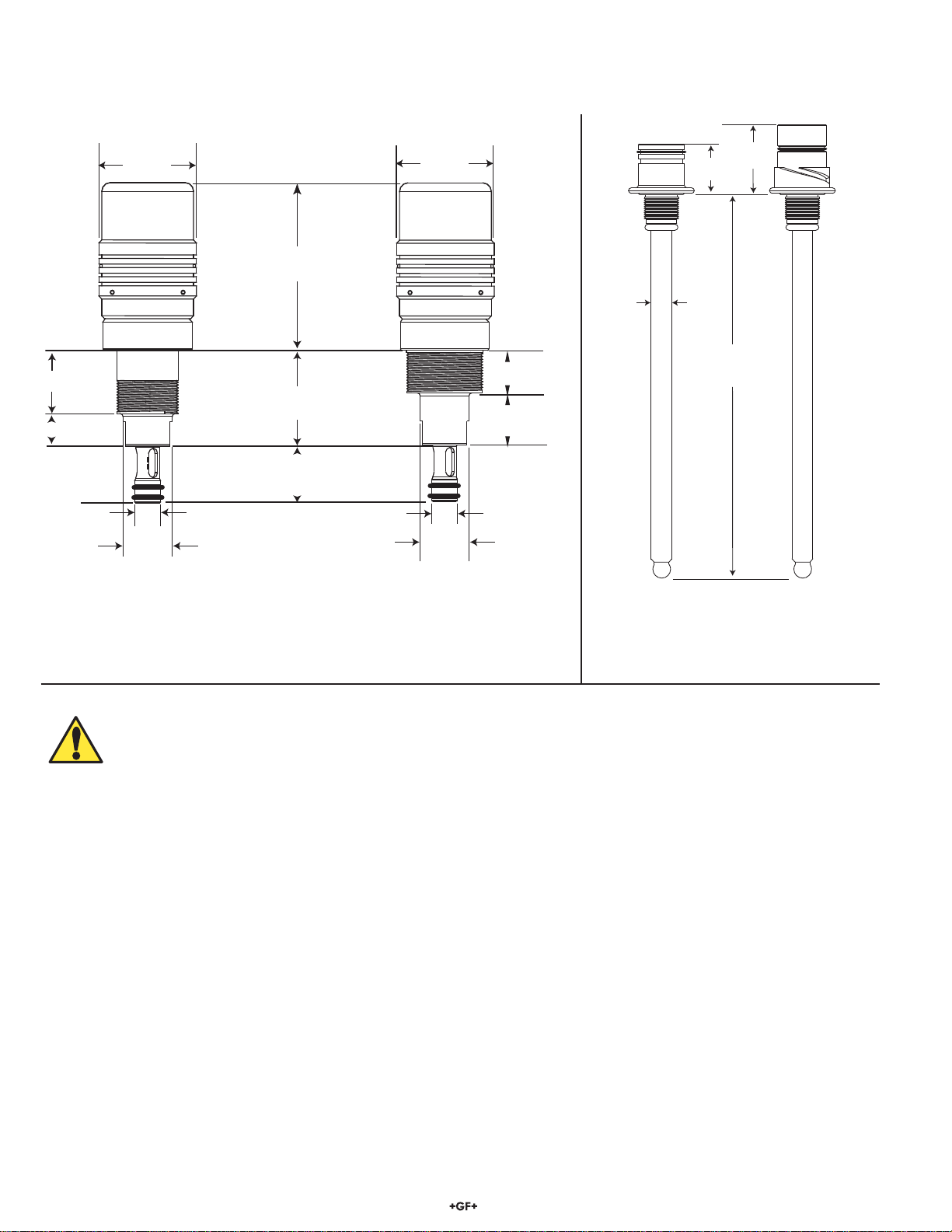
3. Dimensions
12 mm
(0.47 in.)
30,5 mm
(1.2 in.)
218 mm
(8.57 in.)
35 mm
(1.4 in.)
3719-1 Wet-tap
11/2 in. outlet for
21/2 to 4 in. pipe
3719-2 Wet-tap
2 in. outlet for
6 to 12 in. pipe
CAUTION!
When using clamp-on saddle fi ttings (customer-supplied), the system temperature and
pressure is limited by the saddle specifi cations.
The process temperature is limited to 40 °C (104 °F) maximum when using saddles.
2716-WT pH electrode
2717-WT ORP electrode
2756-WT(-1) pH electrode, glass
2756-WTP(-1) pH electrode, plastic
2757-WT ORP electrode, glass
2757-WTP ORP electrode, plastic
2 Signet 3719 pH/ORP Wet-Tap
Page 3
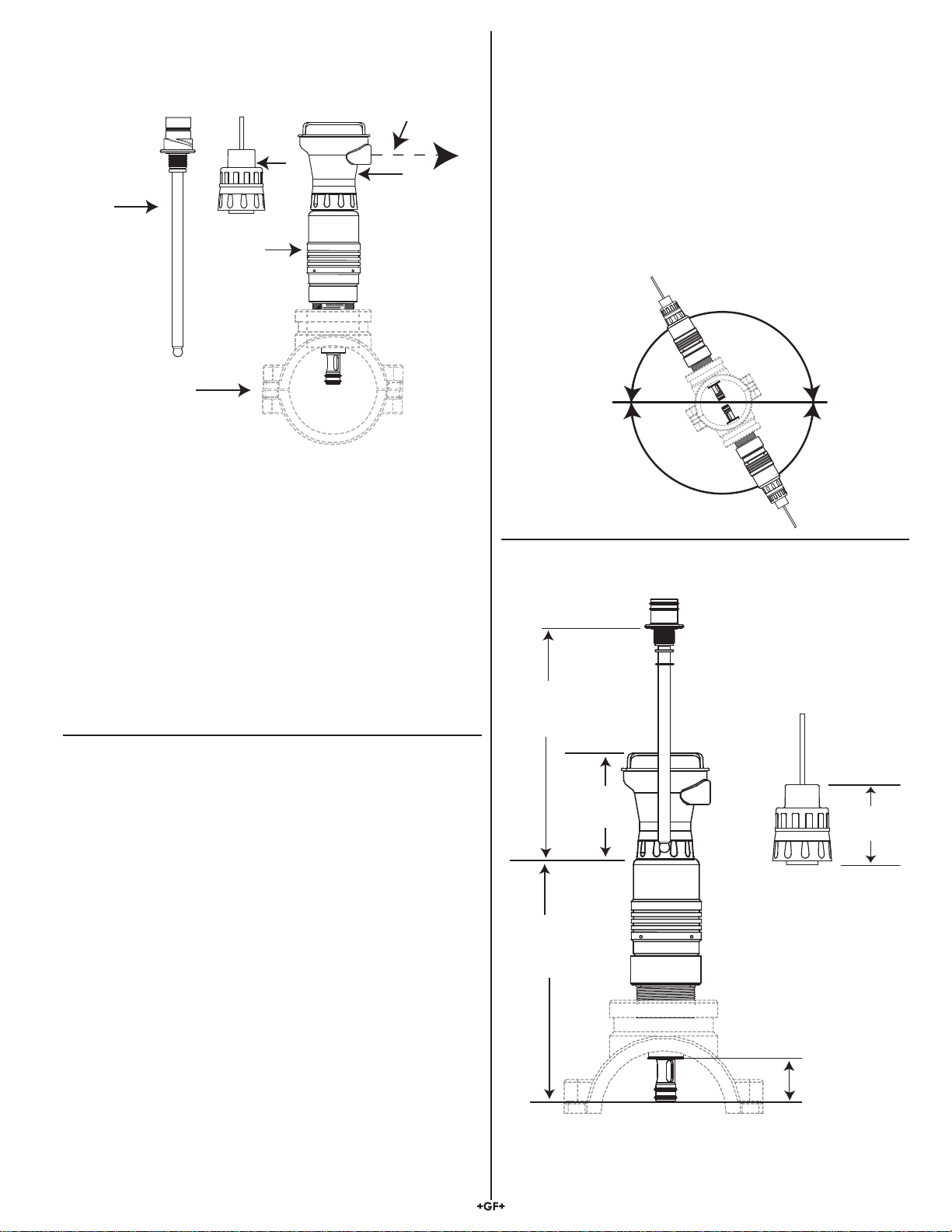
4. 3719 System Overview
a
b
c
d
e
d
a) 3719 pH/ORP Wet-Tap
b) Customer-supplied Low-Profi le Clamp-on Saddle Fitting
(ASTM sizes 2½ to 12 in.)
c) DryLoc® pH or ORP Electrode (6 versions available; see
ordering infomation on page 8.)
("DryLoc®" refers to the electrode connector style)
d) 2750 or 2760 DryLoc® pH/ORP Preamplifi er/Sensor
electronics
e) Output signal options:
2750:
- Digital (S3L)
- 4 to 20 mA
2760:
- Analog mV Output- Digital (S3L)
All components (items a–d) are sold separately.
5. Installation
5.1 Notes on Location, Orientation and Required Clearance
• The 3719-1 is designed for use in pipes up to 4 in.
• The 3719-2 is designed for use in pipes from 6 to 12 in.
• Select a location that will provide suffi cient clearance to
remove and insert the electrode.
• The 3719 can be mounted in any orientation, including
horizontal and inverted. Avoid the 12 o'clock position. In the
presence of sediment, avoid the 6 o'clock position.
• If inverted, use caution when removing the sensor.
Residual fl uid may be present in the retraction housing.
Keep electrode connector clean and dry at all times.
Any angle OK
• Provide 20 inches (minimum) clearance from the top of the
pipe for electrode removal..
218 mm
(8.57 in.)
250 mm
(9.9 in.)
115 mm
(4.5 in.)
OR
89.4 mm
(3.5 in.)
45 mm
(1.75 in.)
3Signet 3719 pH/ORP Wet-Tap
Page 4

5.2 Installation in Pipe Sizes 2.5 to 12 Inches
3-3719-11
pH/ORP Wet-Tap
(Fully Inserted)
• For reliable in-line measurements of pH and ORP, it is
imperative to position the electrode tip into the process
stream.
• Because of its compact “short stroke” design, the 3719
requires low-profi le fi ttings to ensure proper positioning in
pipe sizes DN65 to DN300 (2.5 to 12 inches).
• It is strongly recommended to use low-profi le PP clamp-
on saddle fi ttings (customer-supplied).
• Choose the 3719 version (-11 or -21) appropriate to the size
of the branch connection of the required fi tting:
Use -11 for sizes DN65 to DN100 (2.5 to 4 in), and -21 for
sizes DN150 to DN300 (6 to 12 in.)
5.3 Installation in Pipe Sizes less than 2.5 Inches
• It is possible to install the 3719 into pipe sizes below
2.5 inches by creating a “fl ow cell” with standard piping
components.
• One simple solution, using a tee fi tting and reducer bushings,
is shown in the example below.
3-3719-11
pH/ORP Wet-Tap
1½ in. NPT
Threads
2 in. Tee
(S x S x S)
Flush Style Reducer Bushing
(Spg x FT) 2 in. x 1½ in.
Flush Style Reducer
Bushings (Spg x S)
2 in. x ½ in.
2 in. x ¾ in.
2 in. x 1 in.
2 in. x 1¼ in.
2 in. x 1½ in.
5.4 Installation (Wet-Tap Into Fitting)
The 3719 is packaged with no electrode installed, and with the electrode piston in the fully inserted position.
• Examine the female threads at the top of the electrode piston. Do not install electrode if threads are damaged.
• Examine the two O-rings at the lower end of the assembly. Do not install if O-rings are missing or there are any
signs of damage.
• Lubricate O-rings with a non-petroleum based, viscous lubricant (grease) compatible with the system.
• The pipe can be pressurized after completion of step 4.
• DO NOT ATTEMPT TO REMOVE THE RETRACTION HOUSING FROM A PRESSURIZED PIPING SYSTEM!
• Many similar confi gurations are conceivable in a wide
variety of materials, but be very careful to verify dimensional
compatibility.
• Select an appropriate installation orientation to avoid the
entrapment of air inside the fl ow cell.
• Contact your local Georg Fischer Sales and Support offi ce
for assistance.
Grasp the retraction housing below the locking
shroud; turn the locking shroud 1/4-turn clockwise.
1 2
Pull the locking shroud straight up until
both O-rings are fully seated inside the
retraction housing.
Locking Shroud
Retraction Housing
Lubricated O-rings
4 Signet 3719 pH/ORP Wet-Tap
Page 5

1
2
3
4
OR
OR
Lubricate O-Rings
Lubricate O-Rings
3 4
Turn the shroud 1/4-turn counterclockwise
and lift it completely away from the
electrode piston.
Electrode Piston
The electrode piston is locked in position
by SS locking pins.
DO NOT tamper with the locking pins!
If the piston is depressed with no
electrode installed, the pipe contents are
exposed.
• Thread the Wet-Tap into the pipe fi tting.
• Smaller pipes may require bracing to support the Wet-Tap
weight and the longitudinal forces required for operation.
• Use an appropriate thread sealant to prevent leaks.
• The piping system can now be safely pressurized.
• Inspect the installation for leaks.
5.5 Electrode Installation
Before installation, lubricate O-rings with
a non-petroleum based, viscous lubricant
(grease) compatible with the system.
1. Remove the safety plug from top of
2. Place the Locking Shroud over electrode;
3. Turn the shroud 1/4-turn counterclockwise to
4. Install the matching electronics assembly or
electrode piston. Slide electrode straight
down into electrode piston. Thread electrode
into place until connector shoulder is fl ush
with top of electrode piston. Hand tighten
only.
WARNING:
Do not fl ex the electrode when inserting
into the Wet-Tap assembly. The electrode
can be permanently damaged if it is fl exed
during installation.
turn ¼-turn clockwise to unlock the piston,
then press down fi rmly on the locking
shroud to lower the electrode piston into the
pipe.
lock the piston.
preamplifi er onto the electrode connector.
2750 2760
DO NOT ATTEMPT TO REMOVE THE
RETRACTION HOUSING FROM A
PRESSURIZED PIPING SYSTEM!
5Signet 3719 pH/ORP Wet-Tap
Page 6

5.6 Electrode Removal
The electrode in any pH or ORP system
requires periodic service, calibration or
replacement. When removing the electrode
from the wet-tap assembly, it is very important
to exercise caution and follow the instructions
carefully.
1. Remove the preamplifi er from the top of
the wet-tap assembly.
2. Turn the locking shroud
to unlock the piston.
3. Pull up on the locking shroud to retract the
electrode piston into the pipe.
DANGER!
The piston should retract easily from a pressurized pipe.
If the piston offers resistance, there is a danger that the
piston is coated with deposits from the process.
STOP! DO NOT FORCE THE PISTON UP!
It may damage the O-rings or break off the piston tip.
Return the locking shroud to the LOCKED position and follow the
steps in the box below.
4. Turn the locking shroud ¼-turn counterclockwise and lift up to remove it from the wet-tap assembly.
5. Remove the electrode by turning it counterclockwise.
For safety, keep your body clear of the top of the wet-tap assembly while removing the electrode.
1
/4-turn clockwise
1
2
3 4
3
5
5
DANGER!
If any fl uid is observed leaking from the electrode threads, STOP! DO NOT REMOVE THE ELECTRODE.
There is a danger that the piston tip has been damaged.
Tighten the electrode back down to reseal the assembly and follow the steps in the box below.
If the piston does not retract easily, or if any fl uid is observed leaking from the electrode
threads, the pipe must be drained before the 3719 can be safely removed.
• Stop the fl ow and depressurize the pipe.
• Remove the entire 3719 assembly from the pipe.
• Remove the electrode from the assembly
• Clean any scaling and debris found on or in the piston tip and surrounding area.
6. Electrode Maintenance and Cleaning
Cleaning
Cleaning techniques vary depending on the type of coating present on the glass electrode surface or reference junction.
• Remove soft coatings by vigorous stirring, or with directed spray of a suitable detergent or solvent onto the glass electrode surface.
• Use chlorine bleach or mild detergent to remove soft coatings. Rinse electrode tip in clean water after cleaning.
• Use the least harsh chemical available to remove hard coatings without attacking the materials of construction.
(For example, remove calcium carbonate with a 5% HCL (muriatic acid) solution.
• Remove oily or organic coatings with detergents or an appropriate solvent that does not attack the materials of construction.
• ORP electrode surface (platinum) can be gently sanded with 600 grit wet and dry silicone or carbide sandpaper, jewelers rouge,
crocus cloth, or very fi ne steel wool.
• Never scrape or sand the glass electrode surface.
• Treat glass electrode surfaces with appropriate care to avoid breakage.
• Lubricate O-rings with a non-petroleum based, viscous lubricant (grease) compatible with the system.
Wet-Tap Maintenance
• The Wet-Tap assembly should be operated (retracted) on a monthly basis
• The O-rings on the piston tip should be inspected and lubricated annually, and whenever the system is off line for maintenance.
• Lubricate O-rings with a non-petroleum based, viscous, lubricant (grease) compatible with the system.
6 Signet 3719 pH/ORP Wet-Tap
Page 7

7. Troubleshooting
Offset in pH Electrodes
Electrode offsets occur due to:
• Clogged reference junction
• Aged or contaminated reference solution/wire
• A constant output near 0 mV in all buffer solutions indicates a shorted electrode that must
be replaced.
Check offsets in a pH 7 buffer @ 25 °C. The theoretical output is 0 mV. Any deviation from 0
mV is the pH electrode offset. The mV offset will track across the entire pH range. The slope is
usually not affected by offset changes. (i.e., pH 7= +10 mV, pH 4= +187 mV); slope = 59 mV.
pH Electrode Offset pH 7 buffer @ 25 °C
Theoretical: pH 7.0 (0.0 mV)
New electrode: pH 7 ± 0.25 pH (±15 mV)
Reliable: pH 7 ± 0.85 pH (± 50 mV)
Electrode offsets greater than 0.85 pH (50 mV) indicate the electrode requires cleaning
or replacement. See Maintenance and Cleaning section.
Offset in ORP Electrodes
• ORP electrode offsets are usually caused by clogged reference junctions or by an aged or contaminated reference solution/wire.
• Offsets should be checked in pH 7 buffer saturated with quinhydrone @ 25 °C. The theoretical output is +86 mV.
Any deviation from +86 mV is the ORP electrode offset (e.g., +90 mV).
• Quinhydrone is the oxidizer measured by the ORP electrode and is required for calibration.
To measure ORP electrode offset, saturate 50 mL of pH 4 and pH 7 buffers with ⅛ g quinhydrone.
A new ORP electrode measures these values ±15 mV. The electrode continues to be functional until the offset from these values
exceeds 50 mV. Electrodes with offset greater than 50 mV should be cleaned and replaced if necessary.
Theoretical mV Values @ 25 °C
pH mV
2 +296 mV
3 +237 mV
4 +177 mV
5 +118 mV
6 +59 mV
7 0 mV
8 -59 mV
9 -118 mV
10 -177 mV
11 -237 mV
12 -296 mV
4 pH w/Quinhydrone 7 pH w/Quinhydrone
Temp: 20 °C 25 °C 30 °C 20 °C 25 °C 30 °C
ORP: 268 mV 263 mV 258 mV 92 mV 86 mV 79 mV
Slope in pH electrodes
Electrode slope is the mV output per pH unit. At 25C the theoretical slope is 59.16 mV per pH. The graph below illustrates potential
pH error when a temperature-compensated instrument is not used.
• Coatings on the glass may affect sensor slopes. See Maintenance and Cleaning section.
• Temperature affects electrode slope. Calibrate temperature before calibrating the standard and slope.
°C
23456789101112
pH
15 0.15 0.12 0.09 0.06 0.03 0 0.03 0.06 0.09 0.12 0.15
2500000000000
35 0.15 0.12 0.09 0.06 0.03 0 0.03 0.06 0.09 0.12 0.15
45 0.3 0.24 0.18 0.12 0.06 0 0.06 0.12 0.18 0.24 0.3
55 0.45 0.36 0.27 0.18 0.09 0 0.09 0.18 0.27 0.36 0.45
Slope in ORP electrodes
ORP slope errors are caused by contamination of the platinum electrode surface. Cleaning the electrode surface will usually restore
proper values, response time, and stability. Many systems require both pH and ORP calibration. To conserve calibration reference
solutions, use pH 7 and 4 buffers for pH calibration fi rst. ORP calibration can be performed with the same buffers after adding
quinhydrone.
Response Time/Stability
Response time and stability are affected by the condition of the glass surface (ORP electrode - Platinum surface), reference junction,
and reference solution. Restoration to acceptable levels can often be accomplished by cleaning the electrode's glass surface (ORP
electrode - platinum surface) and reference junction.
pH and ORP electrodes are similar to batteries; they age with time and usage.
The following information will help maximize electrode life:
• High temperatures or concentrated acids/caustics will accelerate electrode aging.
• Never store the electrode tip in deionized (DI) water.
• Never expose electrode to temperatures below –12 °C (10 °F) or allow it to dehydrate. These conditions will damage the electrode.
7Signet 3719 pH/ORP Wet-Tap
Page 8
8. Ordering Information
Mfr. Part No. Code Description
3-3719-11 159 000 804 pH/ORP Wet-Tap, 11/2 in. NPT
3-3719-21 159 000 805 pH/ORP Wet-Tap, 2 in. NPT
3-3719-12 159 000 806 pH/ORP Wet-Tap, ISO 7/1-R 1.5
3-3719-22 159 000 807 Wet-Tap Assembly, ISO 7/1-R 2
Parts and accessories
3-2716-WT 159 000 809 Electrode, pH, twist-lock, bulb, 3 KΩ, wet-tap
3-2717-WT 159 000 811 Electrode, ORP, twist-lock, bulb, 10 KΩ ID, wet-tap
®
3-2756-WT 159 000 834 Electrode, pH, DryLoc
3-2756-WT-1 159 001 383 Electrode, pH, DryLoc®, bulb, 3 KΩ, wet-tap
3-2756-WTP 159 001 390 Electrode, pH, DryLoc®, plastic bulb, PT1000, wet-tap
3-2756-WTP-1 159 001 384 Electrode, pH, DryLoc®, plastic bulb, 3 KΩ, wet-tap
3-2757-WT 159 000 835 Electrode, ORP, DryLoc®, bulb, 10 KΩ ID, wet-tap
3-2757-WTP 159 001 391 Electrode, ORP, DryLoc
3-2750-1 159 000 744 In-line DryLoc® pH/ORP Sensor with J-Box
3-2750-2 159 000 745 In-line DryLoc® pH/ORP Sensor with J-Box and EasyCal
3-2760-11 159 001 367 In-line Preamplifi er with ¾ in. NPT threads and 4.6 m (15 ft) cable
3-2760-21 159 001 368 In-line Preamplifi er with ¾ in. ISO threads and 4.6 m (15 ft) cable
3-2760-31 159 001 369 In-line Connector with 4.6 m (15 ft) cable and ¾ in. NPT threads
3-2760-41 159 001 370 In-line Connector with 4.6 m (15 ft) cable and ISO 7/1R ¾ threads
, bulb, PT1000, wet-tap
®
, plastic bulb, 10 KΩ ID, wet-tap
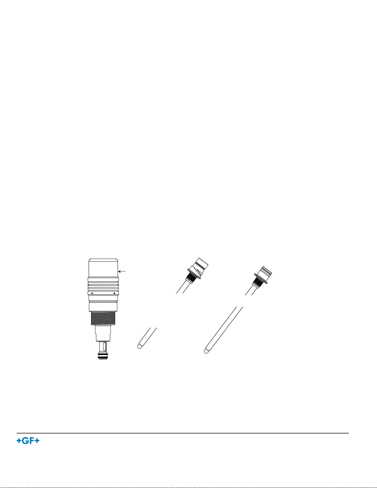
3-3719.390 159 000 855 3719 Locking Shroud
1220-0114 159 000 854 3719 O-ring, FPM, Piston Tip
3-2700.395 159 001 605 pH Calibration Kit: includes 3 Polypropylene cups, box used as stand, 1 pint
pH 4.01, 1 pint pH 7.00
3-0700.390 198 864 403 pH buffer kit (1 each 4,7,10 pH buffer in powder form, makes 50 ml of each)
3822-7115 157 001 606 20 gm bottle Quinhydrone for ORP calibration (must use ph 4.01 and/or pH 7.00
buffer solutions)
3-3719.390
Locking shroud
3-2756-WT Dry-Loc pH electrode
3-2756-WT-1 Dry-Loc pH electrode
3-2756-WTP Dry-Loc pH electrode
3-2756-WTP-1 Dry-Loc pH electrode
3-2757-WT Dry-Loc pH electrode
3-2757-WTP Dry-Loc ORP electrode
1220-0114
O-rings
3-2716-WT pH electrode
3-2717-WT ORP electrode
Georg Fischer Signet LLC, 3401 Aerojet Avenue, El Monte, CA 91731-2882 U.S.A. • Tel. (626) 571-2770 • Fax (626) 573-2057
For Worldwide Sales and Service, visit our website: www.gfsignet.com • Or call (in the U.S.): (800) 854-4090
For the most up-to-date information, please refer to our website at www.gfsignet.com
3-3719.090 Rev L 12/11 English © Georg Fischer Signet LLC 2011
 Loading...