

Page 1
Signet 3519 Flow Wet-Tap Valve
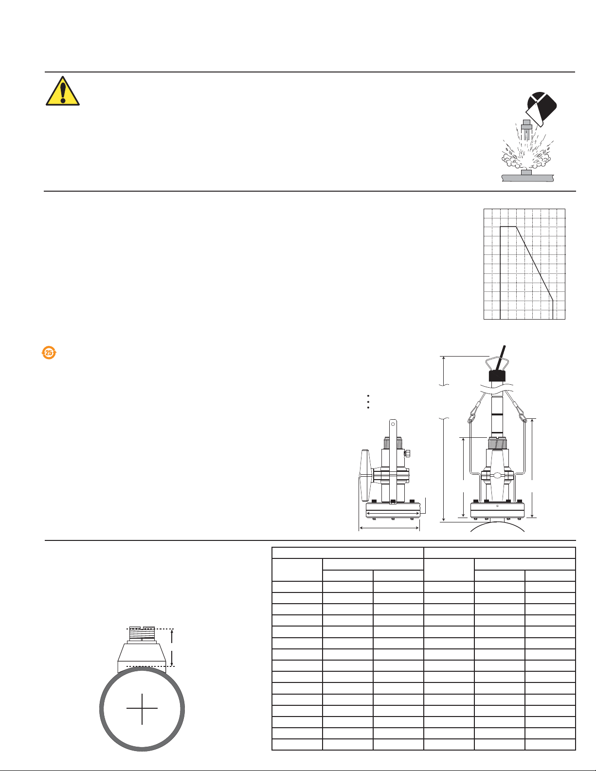
121 mm
(4.75 in.)
137 mm
(5.39 in.)
220 mm
(8.66 in.)
185 mm
(7.28 in.)
Total minimum clearance for
sensor insertion and removal:
1/2 to 4 inch pipe: 737 mm (29 inches)
5 to 8 inch pipe: 762 mm (30 inches)
10 inch and up: 813 mm (32 inches)
*3-3519.090*
3-3519.090 Rev. F 11/12 English
SAFETY INSTRUCTIONS
1. The 3519 Flow Wet-Tap Valve may only be installed into, and removed from, nonpressurized systems (0 psig).
2. The pressure must be reduced to 25 psi when removing or installing the sensor and
must maintain 25 psi or lower while the sensor is removed.
3. Stay clear of sensor stroke area and safety cable during sensor removal.
4. Confi rm chemical compatibility before use.
5. Do not exceed maximum temperature/pressure specifi cations.
6. Wear safety goggles or faceshield during installation/service.
7. Do not alter product construction.
Failure to follow safety precautions may result in severe personal injury!
1. Specifi cations
Compatibility
Signet 515 or 2536 Rotor-X Wet-Tap Flow Sensors
Materials
Body: PVC
Ball seat: PTFE
O-rings: FPM (std); EPR (EPDM) available, contact factory
Standards and Approvals
Manufactured under ISO 9001 for Quality, ISO 14001 for
Environmental Management and OHSAS 18001 for
Occupational Health and Safety.
• CE
• RoHS Compliant
China RoHS(Go to www.gfsignet.com for details)
Fluid Conditions
Pressure/Temperature Ratings:
• 7 bar max. @ 20 °C
(100 psi max. @ 68 °F)
• 1.4 bar max. @ 66 °C
(20 psi max. @ 150 °F)
Dimensions
120
110
100
English
(bar)(psi)
8.3
7.6
6.9
6.2
90
5.5
80
4.8
70
4.1
60
3.4
50
2.8
40
2.1
30
1.4
20
.7
10
0
-20 0
°C
°F
-4
3519 Wet-Tap
20
68 104
40 60
32
140
176
80
2. H-Dimensions
The plastic sensor insert in the Weldolet fi tting MUST be
removed before the welding process. When reinstalled,
it is important that the insert be threaded to the proper
height ("H" dimension).
"H"
Carbon Steel Stainless Steel
Part Number
"H" dimensions
Inches mm inches mm
Part Number
"H" dimensions
CS4W020 2.38 60.45 CR4W020 2.38 60.45
CS4W025 2.33 59.18 CR4W025 2.33 59.18
CS4W030 2.32 58.92 CR4W030 2.32 58.92
CS4W040 2.30 58.42 CR4W040 2.30 58.42
CS4W050 3.09 78.48 CR4W050 3.09 78.48
CS4W060 2.96 75.18 CR4W060 2.96 75.18
CS4W080 2.73 69.34 CR4W080 2.73 69.34
CS4W100 5.48 139.19 CR4W100 5.48 139.19
CS4W120 5.25 133.35 CR4W120 5.25 133.35
CS4W140 5.10 129.54
CS4W160 4.85 123.19
CS4W180 4.60 116.84
CS4W200 4.38 111.25
CS4W240 4.16 105.66
CS4W360 4.10 104.14
Page 2
3. Signet Fittings
Type Description
2 to 4 inch, cut 1-7/16 inch hole in pipe
Over 4 inch, cut 2-1/4 inch hole in pipe
Special order 14 in. to 36 in.
0.5 to 4 inch versions
PVC or CPVC
2 to 4 inch, cut 1-7/16 inch hole in pipe
6 to 8 inch, cut 2-1/4 inch hole in pipe
Available in 10 and 12 inch sizes only
Cut 2-1/2 inch hole in pipe
Weld in place using solvent cement
0.5 to 2 inch versions Carbon steel &
stainless steel
threaded tees
Carbon steel &
stainless steel
Weld-on
Weldolets
2 to 4 inch, cut 1-7/16 inch hole in pipe
Over 4 inch, cut 2-1/4 inch hole in pipe
See section 4 below for details
For pipes DN 65 to 200 mm
Requires a 30 mm diam. hole in the pipe
For pipes from DN 15 to 50 mm
PP or PVDF
Type Description
Plastic tees
Metric
PVC-U
Saddle
Metric
Union
Fitting
PVC
Clamp-on
Saddles
Iron
Strap-on
saddles
PVC
Glue-on
Saddles
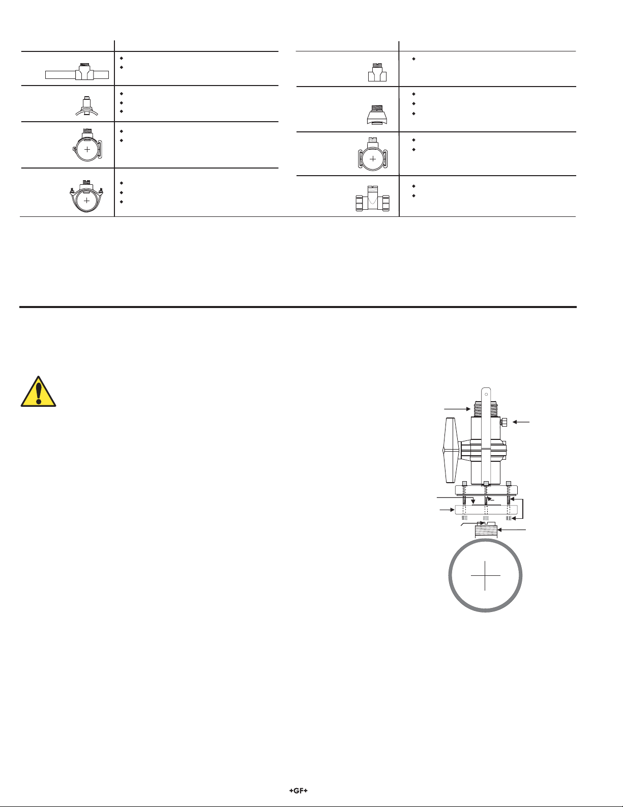
Valve handle
(shown in
open position)
Pressure
relief plug
Align notch and key
under wet tap flange
parallel with pipe.
Allen bolts
and hex nuts
Support plate
Viton O-ring
Key
Sealant
1-1/4 X 11-1/2 in.
NPSM thread
Consult the Signet Measurement and instrumentation Catalog for a complete listing of installation fi ttings.
4. Wet-Tap Valve Installation
The Signet 3519 Flow Wet-Tap Assembly attaches directly to Signet installation fi ttings to enable fl ow sensor removal without system
shutdown. It consists of a fl ange and support plate which thread onto the pipe fi tting insert, and a PVC ball valve through which an
extended length fl ow sensor is inserted into the pipe.
CAUTION: The 3519 Flow Wet-Tap Valve may only be installed into, and
removed from, non-pressurized systems (0 psig).
Procedure
1. Remove six hex nuts and bolts from the Wet-Tap fl ange. Separate the support plate
from the main assembly. Be sure that the Viton O-ring is properly seated in the
support plate groove.
2. Apply sealant to the pipe fi tting insert threads to prevent leaks.To eliminate any
leakage, the valve can be sealed to the fi tting using one of these two methods:
1. Use a silicone RTV such as “GE Sealants and Adhesives Silicone II”.
2. Use a PVC cement such as Christy’s “Red Hot Blue Glue” (for PVC fi ttings) or a
similar PVC pipe cement.
NOTE: This will permanently bond the valve to the installation fi tting and the
fast drying period will not allow for errors in the installation process.
3. Screw support plate onto pipe fi tting insert (O-ring side facing up). It must be
threaded completely down until the notches at the top of the pipe fi tting insert
are exposed.
4. Mount the main Wet-Tap Assembly on the support plate. Make certain the
alignment keys on the fl ange mate with the notches on the pipe fi tting insert.
5. Loosen support plate (holding the main Wet-Tap Assembly in place) until it resists
slightly. Loosen an additional 1/4-turn to seat O-ring.
6. Replace the six hex nuts and bolts to secure the Wet-Tap Assembly in place. Adjust the support plate position as necessary
to align screws.
7. Check the pressure relief plug on Wet-Tap Assembly. It must be closed fi nger tight to prevent leaks.
8. Close ball valve by turning the handle to the fully closed position (parallel with pipe).
2 Signet 3519 Flow Wet-Tap Assembly
Page 3

clamps
safety
cable
Hex
bolts
(6 ea.)
OPEN
SENSOR
STROKE AREA
P3 sensor = 197 mm (7.75 inches)
P4 sensor = 229 mm (9 inches)
P5 sensor = 305 mm (12 inches)
black conduit
cap
PROCESS PIPE
(TOP VIEW)
direction of flow
sensor bale
O-rings
brackets
CLOSED
sensor
bale
sensor
cap
tab
black
conduit
cap
notch
3. Flow Sensor Insertion/Removal
To insert the fl ow sensor:
1. Lubricate O-rings with a non-petroleum based, viscous
lubricant (grease) compatible with the system.
2. Carefully insert the sensor into the 3519 valve assembly until
the fi rst two O-rings seat inside the bore (Figure 1).
• Do not damage the rotor on closed ball valve.
3. Using the clamps, attach the sensor safety cable to the
3519 assembly brackets (hand tighten only).
4. Pull the fl ow sensor upward to remove slack in the safety
cables (Figure 2).
WARNING: Safety cables are factory installed at precise
length. DO NOT attempt to service or replace safety
cables.
WARNING: System pressure must be 25 psi
or less prior to sensor insertion or removal.
5. Open the ball valve (Figure 2).
Figure 1
6. Using a twisting motion, push the fl ow sensor into the 3519
assembly.
• Turn the sensor so the arrows on the black conduit cap
point in the direction of fl ow.
• When properly aligned, the sensor bale will be parallel with
the pipe (Figure 3).
Figure 3
7. Align the tabs under the sensor cap with the notches on the
fi tting insert and tighten the sensor cap (Figure 4).
• HAND TIGHTEN ONLY. DO NOT use any tools that may
damage plastic parts.
Figure 4
Figure 2
To remove the fl ow sensor:
WARNING: System pressure must be
25 psi or less prior to fl ow sensor insertion
or removal. Stay clear of sensor stroke
area and safety cable during sensor
removal.
WARNING: Check the six (6) Hex bolts (Figure 2)
prior to unscrewing the sensor cap. If bolts are loose,
tighten securely before proceeding.
1. Unscrew the sensor cap. (DO NOT use any tools that may
damage plastic parts.)
2. Carefully pull the fl ow sensor upward with a twisting motion
until the safety lanyards are fully extended (Figure 2).
3. Close the ball valve (Figure 1).
4. Loosen the relief plug to depressurize the sensor area.
5. Disconnect the sensor safety cable clamps from the 3519
assembly brackets.
7. The sensor can now be safely removed.
3Signet 3519 Flow Wet-Tap Assembly
Page 4

6. Ordering information
Part Number Code Description
3-3519 159 000 757 PVC wet-tap valve (sensor not included)
P51530-P3 198 840 310 Polypro extended length paddlewheel sensor (0.5 to 4 in.)
P51530-P4 198 840 311 Polypro extended length paddlewheel sensor (5 to 8 in.)
P51530-P5 198 840 312 Polypro extended length paddlewheel sensor (10 to 36 in.)
3-2536-P3 159 000 758 Polypro extended length low fl ow paddlewheel sensor (0.5 to 4 in.)
3-2536-P4 159 000 759 Polypro extended length low fl ow paddlewheel sensor (5 to 8 in.)
3-2536-P5 159 000 760 Polypro extended length low fl ow paddlewheel sensor (10 to 36 in.)
3519/515-P3 159 000 819 Wet-tap assembly with Model 515 paddlewheel sensor (0.5 to 4 in.)
3519/515-P4 159 000 820 Wet-tap assembly with Model 515 paddlewheel sensor (5 to 8 in.)
3519/515-P5 159 000 821 Wet-tap assembly with Model 515 paddlewheel sensor (10 to 36 in.)
3519/2536-P3 159 000 822 Wet-tap assembly with Model 2536 low fl ow sensor (0.5 to 4 in.)
3519/2536-P4 159 000 823 Wet-tap assembly with Model 2536 low fl ow sensor (5 to 8 in.)
3519/2536-P5 159 000 824 Wet-tap assembly with Model 2536 low fl ow sensor (10 to 36 in.)
Georg Fischer Signet LLC, 3401 Aero Jet Avenue, El Monte, CA 91731-2882 U.S.A. • Tel. (626) 571-2770 • Fax (626) 573-2057
For Worldwide Sales and Service, visit our website: www.gfsignet.com • Or call (in the U.S.): (800) 854-4090
For the most up-to-date information, please refer to our website at www.gfsignet.com
3-3519.090 Rev. F 11/12 English © Georg Fischer Signet LLC 2012
 Loading...