

Page 1
Signet PC COMM Confi guration Tool
*3-0251.090*
3-0251.090 Rev. B 10/12 English
English
Operating Instructions
Description
The PC COMM Tool is a Microsoft® Windows®-compatible software
program that is used for confi guration and programming of the Signet 9900
SmartPro™ transmitter using the Signet PC COMM hardware and software.
The software allows the user to select various parameters, enter data,
and interact with the 9900 transmitter via the computer with the same
access as a user has from the 9900’s front panel. Certain parameters
(such as calibration) cannot be changed because access to external
sensors is required.
The PC COMM software allows the user to save the 9900 confi guration
data into a computer fi le and upload a previously stored confi guration data
fi le into the 9900 transmitter.
Specifi cations
Compatibility: Signet 9900
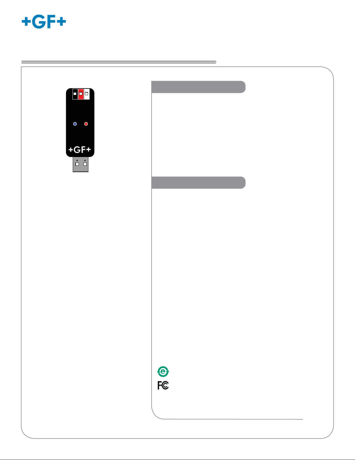
Indicators: Red: POWER ON
Blue: DATA COMMUNICATION
Enclosure: ABS
Input connections: 3-Terminal connectors, Max 14 AWG
Communication rate: Maximum 19.2 kbs
Input power: Computer USB port
Output power: 5 VDC ± 5%
Power consumption: 5 V @ 15 mA
Maximum current source: 50 mA
Maximum cable: 300 m (1000 ft)
Storage temperature: -20 to 100 °C (-4 to 212 °F)
Relative Humidity: 0 to 90% non-condensing
Operating Temperature: -15 to 55 °C (5 to 130 °F)
(USB module only)
General Specifi cations:
Operating System Compatibility:
Windows XP (32-bit version)
Windows Vista
Windows 7 (32- and 64-bit versions)
Memory Requirement: Same as Operating System
Screen Resolution: 1024 × 768 16-bit (or greater) color
Hardware: Signet PC COMM module
Connection: USB interface on the computer.
Manufactured under ISO 9001 for Quality, ISO 14001 for Environmental
Management and OHSAS 18001 for occupational health and safety.
®
China RoHS
Go to www.gfsignet.com for details
This device complies with Part 15 of the FCC rules. Operation is
subject to the following two conditions:
(1) This device may not cause harmful interference, and,
(2) This device must accept any interference received, including
interference that may cause undesired operation.
Microsoft, Windows, and Windows Vista are registered trademarks of
Microsoft Corporation in the United States and other countries.
Page 2
Getting Started
Getting Started
1. Collect the equipment and information that will be required:
• PC COMM Setup Tool (with software installation CD)
• Personal computer with 40 MB free disk space.
• Application-specifi c information.
2. Install the software onto the computer:
Important:
Managed systems and network systems may have security measures
enabled that block the installation of this program.
See the network administrator or IT (Information Technology) staff if
the software cannot be installed.
1. Insert the CD ROM into the computer's CD/DVD drive.
If Autorun is enabled on the computer the installation wizard will start.
If Autorun is disabled on the computer use Windows Explorer to browse the contents of the CD and double-click on the
setup.exe fi le.
2. Follow the prompts in the installation wizard to complete installing the software.
Disconnect power on the 9900 prior to proceeding.
If the 9900 is using the Direct Conductivity/Resistivity Module, the module will need to be removed
from the 9900. Refer to the Direct Conductivity/Resistivity Module Instruction Sheet for instructions.
1. Disconnect power on the 9900.
2. Unplug the sensor connector from the S3L/Frequency input jack on the 9900 and connect the
PC COMM tool in its place.
3. Reconnect power to the 9900.
3. To run the program:
• On the PC, click Start and select Program Files.
• Click on the Georg Fischer group.
• Click on the +GF+ Signet PC COMM icon.
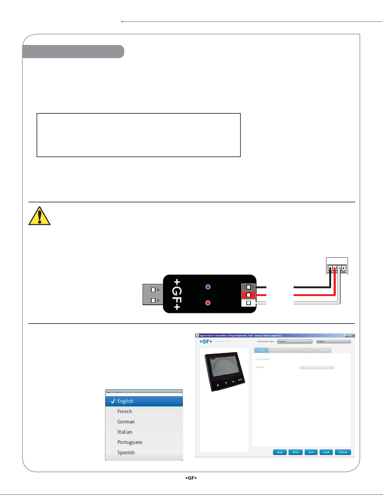
• The Setup screen shown here should be on the
computer display.
• Select a language option from the pull-down menu in
the u
pper right corner.
+5 VDC
Data
Ground
9900
3
L/Freq
S
Connector
SHLD
DATA
GND
V+
2
Signet PC COMM Tool
Page 3

Operation
Operation
4. To initiate communications on the 9900:
If the 9900 transmitter is displaying "Press Enter to Start" it is ready for communication. If the unit was previously confi gured or is
displaying a measurement then from the VIEW mode, press and hold ENTER for three seconds.
Press ► to OPTIONS. Press ENTER.
Press ▲ to REMOTE SETUP menu item.
Press ►. Press ▼ or ▲ to select YES.
Press ENTER. If you are prompted for the password, enter correct password.
Communication is now established between the 9900 Transmitter and the PC COMM tool.
To disconnect from PC COMM, exit the PC COMM software.
Important: If the 9900 Transmitter has not been confi gured prior to communicating with the PC COMM tool, the transmitter will be
in a unique, factory, state. In this state the user will be required to select a measurement sensor type prior to continuing.
On all screens Read, Write, Save, Load, and Default buttons
will appear.
Read causes the application to load the data from the 9900
transmitter and update the software’s display. NOTE: This will
overwrite any changes made in the PC COMM software since
the last Write.
Write causes the data entered to be written to the 9900
transmitter. When your desired changes have been entered
in the PC COMM screens, press WRITE to load your new
settings into the 9900 transmitter.
Save will save the entire PC COMM confi guration, as presently
displayed in the application, to a specifi ed fi le. (You will be
asked to provide a fi le name.)
Load will load a previously saved 9900 confi guration fi le.
NOTE: The fi le must be a 9900 confi guration fi le. The program
will verify that the user-selected fi le is the correct type.
Default will reset all data and all application screens to a
factory default condition. A confi rmation dialog box will be
presented with a warning that all confi guration information will
be erased. Click Write to reset the 9900 to the default values.
NOTE: Default will not change the input type.
The PC COMM tool allows modifi cation of any sensor type/
menu item combination allowed in the 9900.
Choose among the Input, Calibration, Loop, Relay and Option
tabs to choose the desired menu for the selected sensor. All
variables and options available in
the 9900 menus are represented on
PC COMM (except functions such as
calibration that require a sensor to be
connected to the 9900 transmitter).
Refer to the 9900 manual for
details pertaining to specifi c
settings for each sensor type and
menu item.
When confi guration is complete close
the PC COMM software. Disconnect
power from the 9900. Disconnect
the PC COMM tool from the 9900 and reconnect the sensor or
reinstall the Direct Conductivity/Resistivity Module. Reconnect
power to the 9900.
3Signet PC COMM Tool
Page 4

Ordering Information
Mfr. Part No. Code Description
3-0251 159 001 724 PC COMM Tool (includes the PC COMM software, module, and cable)
6682-3004 159 001 725 Terminal Block Plug
32 in.
White (Shield)
Black
Red
Terminal block plug
6682-3004
PC COMM Module
3-0251
Georg Fischer Signet LLC, 3401 Aero Jet Avenue, El Monte, CA 91731-2882 U.S.A. • Tel. (626) 571-2770 • Fax (626) 573-2057
For Worldwide Sales and Service, visit our website: www.gfsignet.com • Or call (in the U.S.): (800) 854-4090
For the most up-to-date information, please refer to our website at www.gfsignet.com
3-0251.090 Rev. B 10/12 English © Georg Fischer Signet LLC 2012
 Loading...