

Page 1
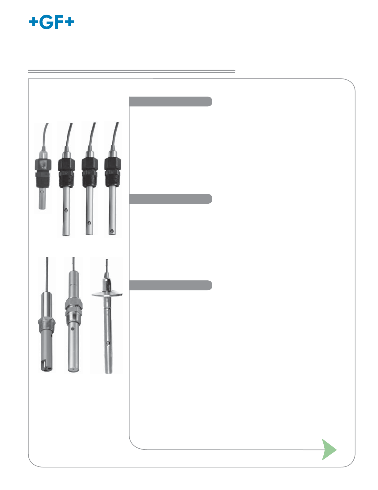
Signet 2818-2823 Series Conductivity Sensor
*3-2820.090*
3-2820.090-1 Rev. N 10/13
Description
English
Operating Instructions
2818
2822
2819
2823
2820
2821
Sanitary
Signet 2818-2823 Conductivity/Resistivity Electrodes are designed to provide
versatile installation and accurate sensing across a very broad dynamic range.
These electrodes are built with a controlled surface fi nish to ensure accuracy and
repeatability. The standard electrode is constructed 316 SS or Titanium, but there are
other materials available for maximum chemical compatibility. Reversible threads or
sanitary fl anges allow for maximum installation versatility.
Sanitary fl ange versions are available with an optional NIST Traceability Certifi cate
to meet USP requirements. Coupled with Signet patented measuring circuitry,
a three decade measurement range is achieved without the need for troublesome
electrode platinization. A platinum RTD (PT1000)
optimal temperature sensing.
located within the electrode allows
Features
• Standard process connections
• ¾” NPT Polypro
• Tri-clamp 1½”, 2”
• Opt. 1/2” NPT 316 SS
• 316 SS or Titanium standard electrode
• Alternative electrode materials available
• Hastelloy-C
• Monel
• In-line or submersible mounting
• NIST traceable certifi ed cells ±1% meet USP requirements
Table of Contents
Description.............................................................................................. 1
Features ................................................................................................. 1
Warranty Statement ................................................................................ 2
Product Registration ............................................................................... 2
Safety Information .................................................................................. 2
Dimensions ............................................................................................. 2
Specifi cations ......................................................................................... 3
Wiring ..................................................................................................... 3
Recommended Position ......................................................................... 3
Maintenance ........................................................................................... 4
In-Line Installation .................................................................................. 4
2822 Submersible Installation ................................................................ 4
2823 Submersible Installation ................................................................ 4
Page 2
General Information and Dimensions
3
Warranty Information
Refer to your local Georg Fischer Sales offi ce for the most
current warranty statement.
All warranty and non-warranty repairs being returned must
include a fully completed Service Form and goods must be
returned to your local GF Sales offi ce or distributor.
Product returned without a Service Form may not be
warranty replaced or repaired.
Signet products with limited shelf-life (e.g. pH, ORP, chlorine
electrodes, calibration solutions; e.g. pH buffers, turbidity
standards or other solutions) are warranted out of box but not
warranted against any damage, due to process or application
failures (e.g. high temperature,
mishandling (e.g. broken glass,
chemical poisoning, dry-out) or
damaged membrane, freezing
and/or extreme temperatures).
Product Registration
Thank you for purchasing the Signet line of Georg Fischer
measurement products.
If you would like to register your product(s), you can now
register online in one of the following ways:
• Visit our website www.gfsignet.com and
click on Product Registration Form
• If this is a pdf manual (digital copy),
click here
• Scan the QR Code on the left
Safety Information
1. Do not remove from pressurized lines.
2. Do not exceed max. temperature/pressure specifi cations.
3. Wear safety goggles or fa shield during installation/service.
4. Do not alter product construction.
5. Disconnect instrument power before wiring this sensor.
6. Failure to follow safety instructions may result in
severe personal injury!
Warning / Caution / Danger
Indicates a potential hazard. Failure to follow all warnings
may lead to equipment damage, injury, or death
Personal Protective Equipment (PPE)
Always utilize the most appropriate PPE during
installation and service of Signet products.
Pressurized System Warning
Sensor may be under pressure, take caution to vent
system prior to installation or removal. Failure to do so
may result in equipment damage and/or serious injury.
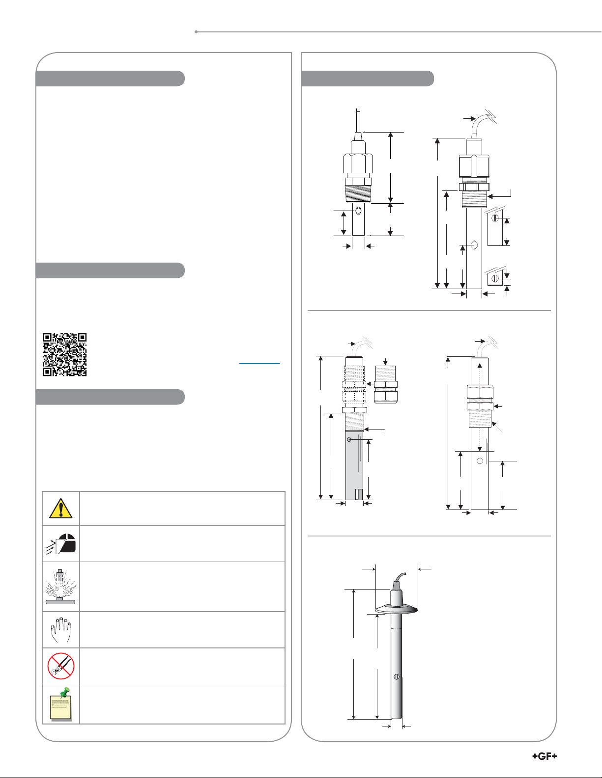
Dimensions
2818
2.39 mm
(1.28 in.)
2822
4.6 m (15 ft.)
cable (std.)
147 mm
(5.8 in.)
submersion fitting
86 mm
(3.4 in.)
19 mm
(0.75 in.)
58.4 mm
(2.3 in.)
73.66 mm
(2.9 in.)
41.91 mm
(1.65 in.)
12.7 mm
(0.50 in.)
¾ in. NPT
Optional 316 SS
kit #3-2820.390
¾ in. NPT
Sanitary
2819, 2820, 2821
4.6 m (15 ft)
cable (std)
152 mm
(6 in.)
107 mm
(4.2 in.)
49.5 mm
(1.95 in.)
12.7 mm
(0.5 in.)
2823
4.6 m (15 ft)
cable (standard)
203 mm
(8.0 in.)
89 mm
(3.5 in.)
19 mm
(0.75 in.)
T1 = 50 mm (2.0 in.)
T2 = 64 mm (2.5 in.)
¾ in. NPT
2820-x
sensor tip
(nosepiece)
20.3 mm
(0.8 in.)
2821-x
sensor tip
(nosepiece)
7.6 mm
(0.3 in.)
Reversible
fitting assy
for submersion
mounting
¾ in. NPT
76.2 mm
(3.0 in.)
Hand Tighten Only
Overtightening may permanently damage product
threads and lead to failure of the retaining nut.
Do Not Use Tools
Use of tool(s) may damage product beyond repair and
potentially void product warranty.
152 mm
(6.0 in.)
126 mm
(5.0 in.)
Note
Tri-clamp is available for
2819, 2820, 2821 only.
T1 or S1 is for 1 to 1½ in.
tees or fl anges.
Note / Technical Notes
Highlights additional information or detailed procedure.
13 mm
2
Signet 2818-2823 Series Conductivity Sensor Instruction Manual
(0.5 in.)
T2 or S2 is for 2 in. tees
or fl anges.
Page 3

Specifi cations and Wiring
*Required
installation
postition for
0.01 cell
Use caution to avoid air bubbles or sediment
trapping inside the electrode cavity.
In-line Submersible
OR
Specifi cations
General
Cell Constant
2818 ................................... 0.01 cm
2819 ................................... 0.01 cm
2820 ................................... 0.1 cm
2821 ................................... 1.0 cm
2822 ................................... 10.0 cm
2823 ................................... 20.0 cm
Operating Range:
2818 ................................... 0.055 to 100 μS (10 kΩ to 18.2 MΩ)
2819 ................................... 0.055 to 100 μS (10 kΩ to 18.2 MΩ)
2820 ................................... 1 to 1000 μS (1 kΩ to 1 MΩ)
2821 ................................... 10 to 10,000 μS (5 to 5000 ppm)
2822 ...................................
2823 ...................................
Cell Constant Accuracy .......... ±2% (certified cells ±1%)
Temp. Compensation Device.. PT1000
Cable Length
Standard ............................. 4.6 m (15 ft)
Maximum ............................ 30 m (100 ft)
2818 & 2819-1 .................... 7.6 m (25 ft) max. when used
Sanitary fitting size .................1 in., 1½ in., 2 in.
Wetted Materials
O-Rings .................................. EPR (EPDM)
Electrodes...............................
Sanitary fitting .........................
2822 Body ..............................CPVC
Insulator Material
2818/2819/2820/2821
2823
.................................... PEEK
.......... Carbon fiber reinforced PTFE
Process Connection ...............¾ in. NPT threads;
Shipping Weight
2818/2819/2820/2821/2822
2823
.................................... 0.3 kg (0.6 lb)
... 0.4 kg (0.8 lb)
Environmental Requirements
Temperature Accuracy ........ 0.3 °C
Max. Pressure/Temperature Ratings
2818/2819/2820/2821 Fittings:
Standard Polypropylene ..... 6.9 bar @ 100 °C (100 psi @ 212 °F)
(3-2820.392) ½ NPT 316 SS
... 13.8 bar @ 120 °C (200 psi @ 248 °F)
Sanitary Connection ........... 6.9 bar @ 120 °C (100 psi @ 248 °F)
2822........................................ 6.9 bar @ 95 °C (100 psi @ 203 °F)
2823........................................ 6.9 bar @ 150 °C (100 psi @ 302 °F)
Standards and Approvals
• RoHS Compliant
China RoHS (Go to www.gfsignet.com for details)
-1
-1
-1
-1
-1
-1
100 to 200,000 μS (50 to 100,000 ppm)
200 to 400,000 μS (100 to 200,000 ppm)
with 8850 & 8860. Do Not splice cable.
316L Stainless Steel (1.4408, DIN 17440)
or Titanium
316L Stainless Steel or Titanium
®
Standard 316 SS fitting &
Optional 316 SS submersion
adapter fitting (3-2820.390)
Wiring
3-9900.092 Direct Conductivity/Resistivity Module
DC Power
Loop Voltage
SHIELD
TEMP (WHT)
ISO GND (BLK)
H COMM Module
SIGNAL (RED)
Cond/Res Module
Red
Black
2818 - 2823
White
Shield
2850 Conductivity/Resistivity Sensor Electronics
Sensr Gnd
(SHIELD)
Gnd
Data
3
2
1
V+
SW1
4
CTS
3
2
ON
1
D3
Temp. IN
(WHITE)
Signal RTN
(BLK)
Signal IN
(RED)
Recommended Position
SHIELD (SILVER)
ISO GND (BLK)
SIGNAL (RED)
TEMP (WHT)
Alternate wetted materials and overall lengths are
available through special order.
Cable length extensions
through special order.
For resistivity measurements above 10 MΩ and/or
below 20°C, maximum cable length is 25 ft. (7.6 m).
to 100 ft. (30 m) are available
Signet 2818-2823 Series Conductivity Sensor Instruction Manual
3
Page 4

Installation and Maintenance
1 2
1-1/4 turns
past finger
tight
3/4 in. NPT
Customer supplied
coupling
Customer supplied
pipe
Sealant
Sealant
Fill with
3 in. to 4 in.
of sealant
Customer
supplied
pipe tee/
reducer
Standard
fitting kit
Mark hole
position
3/4 in. NPT
Hand
tighten only!
O-ring Sealant
Hole up
Customer
supplied
pipe tee/
reducer
Sealant
1-1/4 turns
past finger tight
Hole upMark hole position
Install behind
hole ONLY!
Customer supplied
pipe tee/reducer
3/4 in. NPT
Sealant
Hand
tighten only!
O-ring Sealant
Hole upMark hole
position
Customer
supplied
pipe tee/
reducer
1/2 in. NPT
3-2820.392
Optional
fitting kit
In-Line Installation
2818/2819/2820/2821
2822
2823
*Installation tip: Mark the sensor body to indicate the position of the vent hole. During installation,
align the vent hole mark so it faces upward or against the process fl ow to prevent air bubble entrapment.
2823 Submersible Installation
• Attach ¾ in. watertight pipe to the top of the sensor.
• Secure the threaded connection to prevent any leakage.
• For additional defense against possible accumulation of
condensation at the back seal area of the sensor, fi ll the lower
75 mm to 100 mm (3 in. to 4 in.) of conduit or extension pipe with
a fl exible sealant such as silicone.
2822 Submersible Installation
submersion
#3-2820.390
Georg Fischer Signet LLC, 3401 Aero Jet Avenue, El Monte, CA 91731-2882 U.S.A. • Tel. (626) 571-2770 • Fax (626) 573-2057
For Worldwide Sales and Service, visit our website: www.gfsignet.com • Or call (in the U.S.): (800) 854-4090
For the most up-to-date information, please refer to our website at www.gfsignet.com
3-2820.090-1 Rev N 10/13 English © Georg Fischer Signet LLC 2013
1 2
Optional
fitting kit
Sealant
Customer supplied
pipe
Sealant
Customer supplied
coupling
3/4 in. NPT
1-1/4 turns
past finger
tight
Maintenance
• Any coatings on electrodes will cause readings to drift or show
poor response.
• Clean metallic surfaces with a mild detergent and a non-abrasive
brush or cotton swab.
2823-1 Sensor Tip Removal Procedure:
Sensor tip
(end view)
8-32
A
C
D
Sensor tip
(side view)
Electrode
Sensor tip
(side view)
Electrode
Insulator
Insulator
B
Cotton swab
Clean electrode
Clean metal body
 Loading...