

Page 1
Signet 3-2630-X Amperometric Free Chlorine Electrode
Signet 3-2632-X Amperometric Chlorine Dioxide Electrode
*3-2630.090*
3-2630.090
1. Description
The Signet Amperometric Chlorine Electrodes are designed to measure chlorine in fresh, clean water treatment applications.
Free Chlorine electrodes are available in measurement ranges of 0 to 2 ppm, 0 to 5 ppm or 0 to 20 ppm.
Chlorine Dioxide electrodes are available in measurement ranges of 0 to 2 ppm.
Electrodes require the Signet 2650 Amperometric Electronics to output a digital (S3L) signal to the Signet 8630 Chlorine Transmitter
Features:
• Utilizing smart-sensor technology, this electrode incorporates a unique embedded memory chip within the electrode to
• Signet's patented DryLoc® connector provides quick assembly and a secure connection. Gold-plated contacts and an O-ring
• Integrated temperature element for automatic temperature compensation.
• Separate drive electronics (Signet 2650) allow easy electrode replacement without running new cable.
Rev. M 09/13
CAUTION!
1. Follow instructions carefully to avoid personal injury or damage to electrode.
2. Prior to installation or removal:
a. Disconnect fl ow through system.
b. Drain below sensor level.
3. Confi rm chemical compatibility before use.
4. Do not exceed the maximum pressure or temperature specifi cations.
5. Do not alter product construction.
1. Description p.1 5. Maintenance p.2 9. Overview p.5
2. Sensor Preparation p.1 6. Storage and Disposal p.3 10. Troubleshooting p.6
3. Operation p.2 7. Installation p.4 11. Ordering p.7
4. Calibration p.2 8. Mounting Position p.4 12. Technical Data p.8
communicate a wide variety of information to the Signet 2650 electronics and Signet 8630 transmitter. Electrode type,
factory calibration data, service time, chlorine range, high and low pH (with optional Signet pH electrode), temperature limits
and more are stored on the chip. This information is accessible via the Signet 8630 transmitter.
seal ensure a waterproof and reliable interconnect to the Signet 2650 Amperometric Electronics.
English
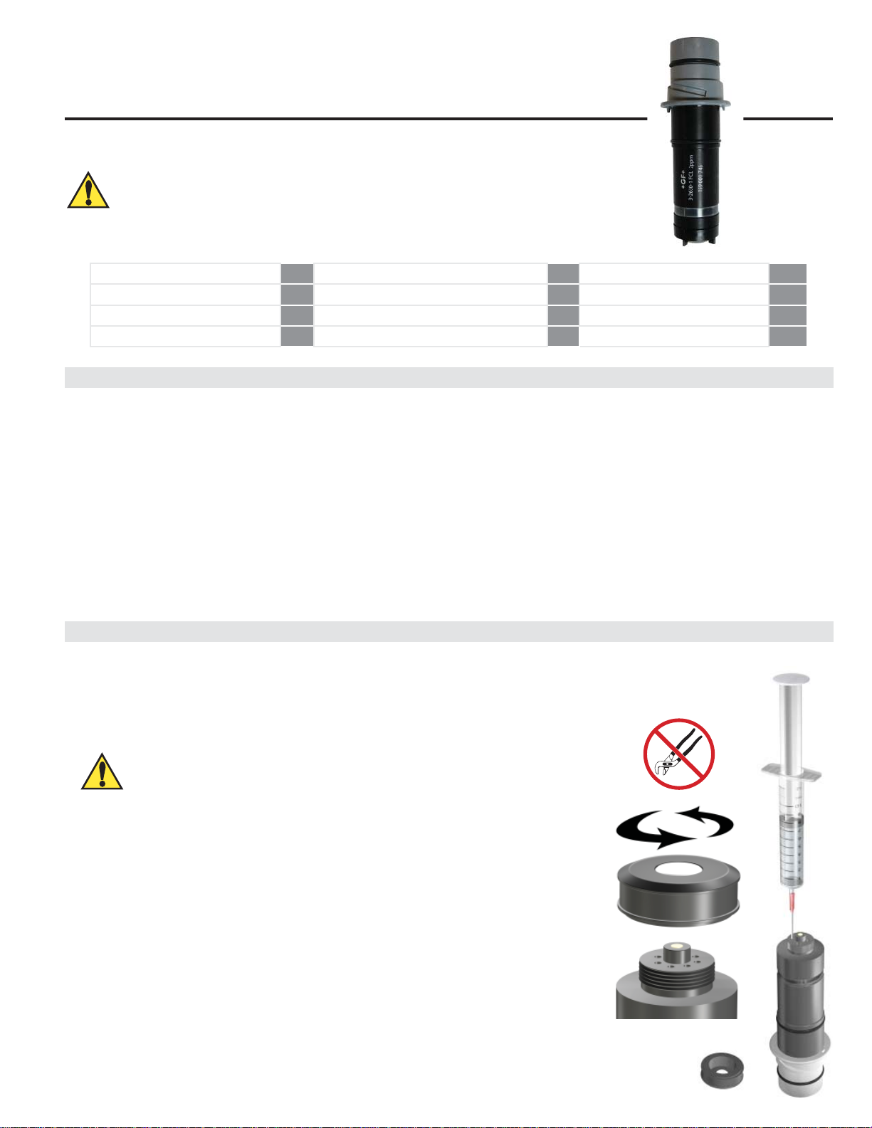
2. Sensor Preparation
• Chlorine sensors are shipped without internal electrolyte solution.
• Prior to installation and supplying power, Chlorine sensors must be fi lled with the appropriate internal electrolyte solution.
• Verify the correct electrolyte solution is utilized with the corresponding sensor.
• Free Chlorine and Chlorine Dioxide sensor require different electrolyte solutions.
Avoid skin or eye contact with electrolyte solution.
Wear rubber gloves and goggles.
* Material Safety Data Sheets (MSDS) are available online at www.gfsignet.com.
CAUTION:
Initial Fill Procedure:
When adding electrolyte, be prepared for an accidental spill.
Working near a sink is recommended.
1. Remove the protective bottle from the end of the electrode
2. Remove the membrane cap from the front of the sensor.
Note: When new sensors are shipped, the membrane cap is not tightened to the sensor
3. Fill supplied syringe with electrolyte solution.
4. Place the electrode on a level surface.
5. Insert syringe needle fully into one of the eight electrode holes while injecting with
electrolyte solution. Slowly injecting the electrolyte solution into the sensor to avoid
introducing air bubbles. The electrode holds approximately 14 milliliters of solution.
Slowly fi ll until solution begins to fl ow out of holes. Do not allow the solution to run
down the electrode and wet the electrical contacts in the DryLoc connector.
6. Slowly screw on the membrane cap fi nger tight. Do not use tools.
To avoid damage and contamination, do not touch the white membrane surface on
the membrane cap.
DO NOT touch the gold tip or the membrane of the sensor.
Page 2
3. Operation
Electrode Range: The electrode must match the type and range of
chlorine concentration to be measured.
Flow Rate:
The electrode must have a stable and constant fl ow of water past its
membrane for accurate measurement. When the sensor is installed
in the Tee fl ow cell 3-3610-2 (159 001 684), the fl ow rate must range
from 37.8 to 75.7 LPH (10 to 20 US g/h).
When the sensor is installed in the Flow Cell Block
3-4630.392 (159 001 690), the fl ow rate range should be
30.24 to 45.36 LPH (8 to 12 US gph).
Sensor Conditioning: 4 hours
A new electrode requires conditioning of 4 hours with the electrode
powered on and water fl owing past the head to generate a
stable reading.
Subsequent start-ups can require an electrode conditioning of up to two hours.
Part Number Chlorine Range Chlorine Type
3-2630-1 0 to 2 ppm (mg/L)
Free chlorine3-2630-2 0 to 5 ppm (mg/L)
3-2630-3 0 to 20 ppm (mg/L)
3-2632-1 0 to 2 ppm (mg/L) Chlorine Dioxide
The electrode should not be used in water
containing surfactants, oils, organic chlorine
or stabilizers such as cyanuric acid.
The maximum allowable operating pressure
must be less than 0.48 bar (7 psi).
Higher pressures will damage the electrode.
4. Calibration
A new chlorine electrode or one that has had the membrane cap changed must be calibrated. Refer to the Signet 8630 Chlorine
Transmitter manual for electrode and instrument calibration information. A diethyl-p-phenylenediamine (DPD) colorimeter test kit
(not included) is required for sensor calibration. A sample is taken and analyzed with the DPD test kit, then this value is entered into
the Signet 8630 transmitter.
• Calibrate after a membrane cap change.
• Check calibration one day after sensor is placed in service.
• Check calibration weekly to monthly depending on process requirements.
5. Maintenance
Verifying the sensors accuracy using the DPD method should be performed to determine if the sensor requires maintenance.
1. Inspect the membrane for dirt or damage. Replace the membrane if its torn or if the gold cathode is visible.
2. If the membrane is dirty clean the membrane by soaking it in 1 - 5% HCL and gently washed with a stream of DI water.
(do not use any mechanical device on the membrane)
Diluted HCl can irritate the eyes and skin, use proper safety equipment.
Do not use surface tension reducing chemicals, detergents or solvents on the membrane.
If a fresh water rinse does not clean the membrane, it will need to be replaced.
Keep spare membrane caps available. Membrane caps carry no warranty.
Avoid skin or eye contact with electrolyte solution.
Wear rubber gloves and goggles.
* Material Safety Data Sheets (MSDS) are available online at
www.gfsignet.com.
Additional caution should be taken when handling the
Chlorine Dioxide electrolyte solution.
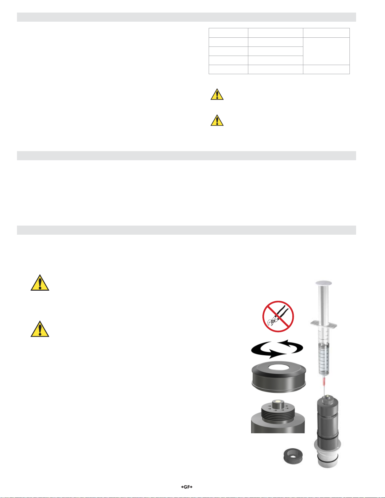
Refi ll Procedure:
When adding electrolyte, be prepared for an accidental spill.
Working near a sink is recommended.
1. Remove the membrane cap from the front of the sensor.
2. Turn the sensor upside down and shake the sensor vigorously to remove the
internal electrolyte.
3. Fill supplied syringe with electrolyte solution.
4. Place the electrode on a level surface.
5.
Insert syringe needle fully into one of the eight electrode holes while injecting with
electrolyte solution. Slowly injecting the electrolyte solution into the sensor to avoid
introducing air bubbles. The electrode holds approximately 14 milliliters of solution.
Slowly fi ll until solution begins to fl ow out of holes. Do not allow the solution to run
down the electrode and wet the electrical contacts in the DryLoc connector.
6. Slowly screw on the membrane cap fi nger tight. Do not use tools.
To avoid damage and contamination, do not touch the white membrane surface
on the membrane cap.
2 263X Series Chlorine Electrodes
Page 3
6. Storage and Disposal
Store electrode between –10 ºC to 60 ºC (–14 ºF to 140 ºF) at a relative humidity that does not exceed 95%.
DO NOT
FREEZE
6.1. Storage of the Sensor
If the sensor or panel assembly is to be removed from service for a period of time the sensor must be properly prepared for storage
and may need to be recommissioned.
Storage periods of 1 week or less:
• Close the drain valve, then close the inlet valve of the fl ow cell, to maintain water inside the fl ow cell to keep the membrane wet.
• If draining the fl ow cell is required, remove the sensor from the cell and the 2650 electronics and store in the shipping bottle with
tap water added.
Storage periods greater than 1 week, but less than 2 months:
• Remove the membrane cap and internal electrolyte solution.
• Rinse the sensor internal chamber with DI water or cold tap water; drain and allow to dry.
• Place the membrane cap back onto the sensor. INSTALL LOOSE, DO NOT COMPLETELY TIGHTEN THE CAP.
WHEN STORED DRY, THE MEMBRANE CAP MUST BE STORED RELAXED AND UNSTRESSED.
• Store sensor DRY in the shipping bottle, DO NOT ADD WATER.
The primary concerns when storing the electrode is membrane dehydration and freezing in extremely cold environments.
Recommissioning Procedure:
1. Fill the sensor with the electrolyte as outlined in Maintenance, Section 3, and install the membrane cap.
2. The sensor will have to be polarized in the fl ow cell with fl owing Chlorinated water before being used.
Note: This may take 30 to 120 minutes before calibration can be performed.
3. If the sensor does not recover after recommission, follow steps 1-10 outlined under
"Storage periods greater than 2 months."
4. If the sensor still fails to work properly, continue with steps 11-17.
Storage periods greater than 2 months:
• If the sensor has been in storage for a long period of time, or used in a chlorine free environment, the sensor may develop
a low slope (output), which may cause the sensor to have a slow response time.
• In this case, the sensor must be reconditioned.
Required to recondition a sensor:
• DI Water
• Beaker (any size available)
• Polishing Sheets (Included in sensor maintenance kit)
• Free Chlorine: Chlorine Bleach (13% concentration)
• Chlorine Dioxide: Aqueous Chlorine Dioxide solution
CAUTION!
Bleach
and Chlorine Dioxide solutions are
very corrosive and
may release dangerous gases if it comes in contact with acids.
• Wear proper protective clothing (gloves and eye protection)
• Avoid contact with skin and eyes
• Observe all warnings on safety data sheets
• Avoid spilling bleach and possible contact with acids
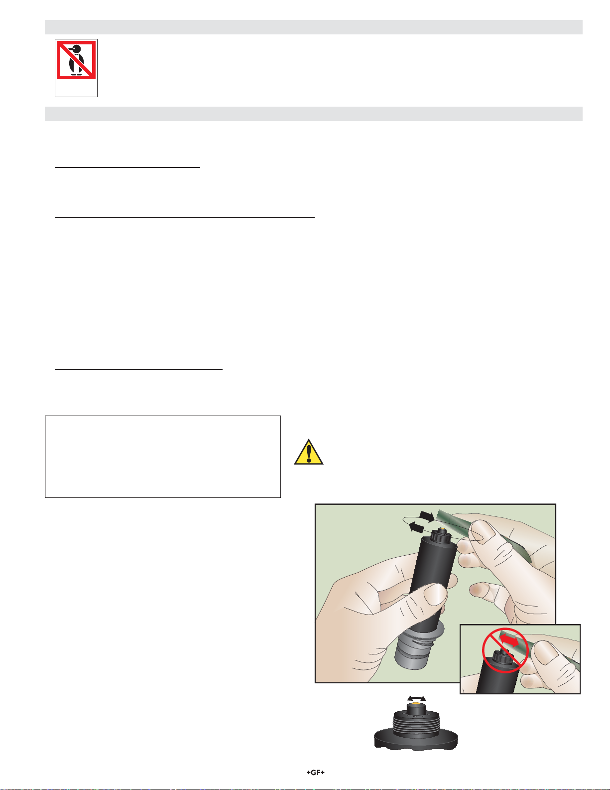
Reconditioning Procedure:
1. Remove the sensor from the 2750-7 electronics.
2. Remove the membrane cap.
3. Place the sensor on a fi rm fl at surface with the gold
cathode pointing upward.
4. Apply a small amount of water to the Blue (Course)
polishing paper (dull side).
5. Polish the gold electrode by moving the paper in a
circular pattern for 30 seconds. DO NOT go back and
forth in a single direction. See Figure 1.
6. Rinse the sensor tip with DI water.
7. Apply a small amount of DI water to the White
(Fine) polishing paper (dull side) and polish the gold
electrode by moving the paper in a circular pattern for
30 seconds. DO NOT go back and forth in a single
direction. See fi gure 1.
8. Rinse the sensor tip with DI water.
9. Top off the sensor with electrolyte and inspect
Figure 1
Curved Surface
membrane for dirt or damage. Replace if necessary.
10. Insert the sensor into the 2650 electronics and apply
power.
(Steps 11-17, See Next Page)
3263X Series Chlorine Electrodes
Page 4

6.1. Storage of the Sensor continued
Reconditioning Procedure Continued:
(Steps 1-10, See Previous Page)
11. Fill beaker with a 12 mm (½ inch) of the appropriate solution.
12. Position or suspend the sensor 0.2 mm to 12 mm (¼ in. to ½ in.) above the appropriate
solution. DO NOT SUBMERGE THE SENSOR. See Figure 2.
13. Apply power to the system.
14. Monitor the nA of the sensor (press the down arrow once on the 8630 transmitter).
The nA reading should start to rise. Response time and nA reading will depend upon the
temperature of the bleach.
15. Once the sensor's nA reading reaches approximately 300-360 nA allow the sensor to
remain in the beaker, suspended over the appropriate solution, for an additional 20 minutes.
• If sensor does not recover quickly, cover the beaker to avoid air contamination.
• Contact the factory for assistance (www.gfsignet.com).
16. After 20 minutes, remove the sensor and install it into the fl ow cell and
restore fl ow to the system.
17. Calibrate the sensor after the system has become stable.
6.2. Disposal
The electrode is not recyclable. Dispose of properly according to local, state and federal guidelines.
7. Installation
Figure 2
Align tab on electrode with notch on
fi tting. Insert until fully seated.
Lubricate O-rings with a non-petroleum
based, viscous lubricant (grease)
compatible with the system.
Do Not Use Lubricant or Sealing Tape on Threads.
Do Not Overtighten. Do Not Use Tools.
8. Mounting Position - PVC Tee
Best
45º or or45º
Flow
4 263X Series Chlorine Electrodes
Good
Flow Direction
Page 5

8. Mounting Position continued
Mount the fl ow cell where the sensor will be easily accessible.
To avoid air bubble entrapment, do not mount with downward fl ow.
NO
Flow
9. Overview
Chlorine in Water
Various forms of chlorine are used to disinfect water. Each form of chlorine has benefi ts and limitations which help determine the
specifi c application. The predominant categories used in disinfection are Free Chlorine, Total Chlorine and Chlorine Dioxide. Free
Chlorine is the sum of chlorine gas (Cl2), hypochlorous acid (HOCl) and hypochlorite (OCl-). Above pH 4.0 all of the molecular
chlorine is converted to HOCl and OCl-. Hypochlorous acid is a more potent disinfectant than hypochlorite and exists in a pH
dependent equilibrium as shown in Figure 3.
Free chlorine also combines with naturally occurring or human-introduced nitrogen compounds in the water to form chloramines, also
known as combined chlorine. Treatment operators introduce ammonia into the water to form monochloramine (NH
(NHCl2) and trichloramine (NCl3). Chloramines are a less effective disinfectant but have a longer residence time than the free chlorine
species. Total chlorine is the sum of free chlorine (Cl2, HOCl and OCl-) and combined chlorine (NH2Cl, NHCl2, NCl3).
Chlorine Measurement by Amperometric Sensors
Signet chlorine sensors are membrane-covered amperometric 2-electrode sensors. A gold or platinum cathode acts as the working
electrode with a silver halide acting as the counter electrode. Depending on the species to be analyzed, a polarization voltage is
applied between the two electrodes. When placed into service, the chlorine species of interest diffuses across the membrane and
is reduced at the cathode surface. For the case of total chlorine, the analyte reacts with the fi ll solution to produce an intermediate,
which is subsequently reduced at the cathode surface. At the same time, the silver anode is oxidized to form a silver halide. The
current generated at the cathode is proportional to the rate of diffusion through the membrane and the concentration of chlorine in the
sample. The current from the cathode to the anode is conditioned, digitized and transmitted by the associated electronics.
Cl), dichloramine
2
pH Compensation for Free Chlorine
Amperometric free chlorine sensors measure only hypochlorous
acid. As noted in the text above and in Figure 3, the ratio
of hypochlorous acid and hypochlorite is pH dependent. In
many applications the process pH is relatively stable and no
correction is needed. However, where the pH of the water
changes signifi cantly, accurate free chlorine measurement
requires pH compensation. With the addition of a pH sensor, the
Signet 8630 transmitter will automatically compensate the free
chlorine reading for changes in pH.
Automatic pH Compensation and Free Chlorine
In many applications, the process pH does not signifi cantly
fl uctuate and only a chlorine sensor and instrument are
necessary for accurate chlorine measurement.
It is when the pH varies that free chlorine concentration can
not accurately be determined without the use of automatic pH
compensation.
The addition of the Signet 3-2724-00 (159 001 545) pH
electrode along with its 3-2750-7 (159 001 671) preamplifi er
to the system makes pH compensation extremely easy and
automatic even with wide fl uctuations or high pH.
See Figure 4 for pH variation recommendations.
Example:
If the pH nominal value is 7.5 and the pH variation is ±0.2 then
automatic pH compensation is recommended.
If the pH nominal value is 7.0 and the pH variation is ±0.2 then
automatic pH compensation is not required.
100
90
80
70
60
50
40
30
% free chlorine
20
10
0
5.0 5.5 6.0 6.5 7.0 7.5 8.0 8.5 9.0 9.5 10.0
HOCl
OClØ
±0.3
±0.2
pH variation
±0.1
0
6.5 7.0 7.5 8.0 8.5 9.0
Automatic pH compensation recommended
=
in ranges within shaded area
pH at 25 °C
Sample pH
Figure 3
Figure 4
5263X Series Chlorine Electrodes
Page 6

10. Troubleshooting
Transmitter error messages related to calibration are detailed in the Signet 8630 Chlorine Transmitter operation manual.
Problem Possible Causes Remedies
Condition for 4 hours minimum prior to initial
calibration
Sensor cannot be calibrated.
Output is higher than DPD test
(out of range).
Sensor conditioning time too short
Interference from contaminants See technical data
Membrane cap damaged Replace cap and recondition
DPD chemicals bad Use fresh reagents
pH outside of working range See technical data
Sensor cannot be calibrated.
Output is lower than DPD test.
Sensor output very low
Unstable output from sensor
Sensor conditioning time too short
Chlorine content too low
Low fl ow rate Check to make sure fl ow rate is suffi cient
Air bubbles on electrode membrane
Low or no electrolyte in electrode Fill electrode with electrolyte
Organic chlorination agents present in water See technical data
Surfactants in water Remove surfactants and replace cap
Membrane cap coated Clean or replace membrane cap
Membrane cap loose Tighten or replace membrane cap
pH outside working range. See technical data
Sensor conditioning time too short
Chlorine content too low Add chlorine to validate
Only bound chlorine present. No free chlorine Check for chloramine with appropriate DPD test
Electrode not making good contact with electronics Inspect and reconnect
Air bubbles on electrode membrane
Membrane damaged
Electrode not making good contact with electronics Inspect and reconnect
Non-sensor problem
Condition for 4 hours minimum prior to initial
calibration
DPD value must be greater than 0.5 ppm to
calibrate
Inspect visually. Tap to remove bubbles. Mount
at an angle.
Condition for 4 hours minimum prior to initial
calibration
Inspect visually. Tap to remove bubbles. Mount
at an angle.
Replace membrane. Condition sensor for at
least 2 hours and recalibrate.
Check 3-2650 Electronics connection to
electrode (see 3-2650 manual for instructions).
Make sure connections are dry. Check
instrument hookup.
6 263X Series Chlorine Electrodes
Page 7

11. Ordering Information
Mfr. Part No. Code Description
3-2630-1 159 001 746 Free Chlorine electrode, 0 to 2 ppm (mg/L)
3-2630-2 159 001 662 Free Chlorine electrode, 0 to 5 ppm (mg/L)
3-2630-3 159 001 747 Free Chlorine electrode, 0 to 20 ppm (mg/L)
3-2632-1 159 001 767 Chlorine Dioxide electrode, 0 to 2 ppm (mg/L)
Accessories and Replacement Parts
Mfr. Part No. Code Description
3-2630.391 159 001 674 Free Chlorine electrolyte, 30 mL
3-2632.391 159 310 160 Chlorine Dioxide electrolyte solution, 30 mL
3-2630.392 159 001 675 Free Chlorine replacement PVDF membrane (1) (sensors sold prior to Nov 1, 2012)
3-2630.394 159 310 164
3-2630.396 159 001 676 Free Chlorine maintenance kit - (2) electrolyte, (2) PVDF membranes, and Polishing Paper
3-2630.398 159 310 166 Free Chlorine Sensor maintenance kit - (2) electrolyte, (2) PTFE membranes, (2) Silicone Bands,
3-2632.398 159 310 165 Chlorine Dioxide maintenance kit - (2) electrolyte, (2) PTFE membranes, (2) Silicone Bands, and
3-2600.510 159 500 422 Silicone Band, Chlorine electrode
Free Chlorine and Chlorine Dioxide Replacement PTFE membrane (1) (sensors sold after Nov 1, 2012)
(sensors sold prior to Nov 1, 2012)
and Polishing Paper (sensors sold after Nov 1, 2012)
Polishing Paper
7263X Series Chlorine Electrodes
Page 8

12. Technical Data
Dimensions
25.15 mm (.99 in.)
General
Polarization Source:
Signet 2650 Amperometric Electronics
Compatible Flow Cells:
Signet 3-3610-1 (159 001 683)
Signet 3-3610-2 (159 001 684)
Signet 3-4630.392 (159 001 690)
Mounting:
Signet DryLoc connection
Materials:
CPVC
Free Chlorine (prior to Nov 1, 2012):
Membrane material: PVDF
Free Chlorine (after to Nov 1, 2012) and Chlorine Dioxide:
Membrane material: PTFE
Free Chlorine and Chlorine Dioxide:
O-ring material: FPM
Working electrode: Gold
Counter reference electrode: Silver halide
Wetted Materials:
PVC, PVDF or PTFE, FPM, Nylon, Silicone
Performance
Electrode:
Repeatability: ± 0.08 ppm (mg/l) or 3% of selected
range whichever is less
Free Chlorine Slope: 10 to 60 nA/ppm (mg/l) @ 25 ºC
Chlorine Dioxide Slope: 40 to 200 nA/ppm (mg/l) @ 17 ºC
Response time, T90: < 2 minutes
System: (including electronics and instrument)
Accuracy: < ±3% of electrode signal after calibration
Resolution: ≤ 0.5% of electrode range
Sensor Conditioning:
New, fi rst start-up: 4 hours maximum before calibration
Subsequent start-ups: 2 hours maximum
Temperature Element:
PT1000
74.4 mm (2.93 in.)
26.4 mm (1.04 in.)
109.2 mm (4.3 in.)
Operational Ranges and Limits
Free Chlorine:
Range: 3-2630-1: 0 to 2 ppm (mg/L)
3-2630-2: 0 to 5 ppm (mg/L)
3-2630-3: 0 to 20 ppm (mg/L)
pH Operating Range:
5.5 pH to 8.5 pH
Chlorine Dioxide:
Range: 3-2632-1: 0 to 2 ppm (mg/L)
pH Operating Range:
Maximum
Operating
4.0 pH to 11 pH
T emperature:
0 °C to 45 °C (32 °F to 113 °F)
Maximum Operating Pressure:
Membrane: 0.48 bar @ 25 °C (7 psi @ 77 °F)
Flow Velocity Across Membrane Surface:
Minimum: 15 cm/s (0.49 ft/s)
Maximum: 30 cm/s (0.98 ft/s)
Free Chlorine Cross Sensitivity:
Chlorine Dioxide, ozone, bromine
Chlorine Dioxide Cross Sensitivity:
Free Chlorine, ozone
Chemical Compatibility:
< 50% ethanol/water, < 50% glycerol/water
Environmental Requirements
Storage Temperature (dry):
-10 ºC to 60 ºC (-4 ºF to 140 ºF)
System Temperature:
-10 ºC to 60 ºC (-4 ºF to 140 ºF)
Relative Humidity:
0 to 95% indoor/outdoor non-condensing to rated ambient
Standards and Approvals
CE, WEEE
Manufactured under ISO 9001
RoHS Compliant
China RoHS (Go to www.gfsignet.com for details)
Declaration of Conformity according to FCC Part 15
This device complies with Part 15 of the FCC rules.
Operation is subject to the following two conditions:
(1) This device may not cause harmful interference, and,
(2) This device must accept any interference received,
including interference that may cause undesired operation.
Georg Fischer Signet LLC, 3401 Aero Jet Avenue, El Monte, CA 91731-2882 U.S.A. • Tel. (626) 571-2770 • Fax (626) 573-2057
For Worldwide Sales and Service, visit our website: www.gfsignet.com • or call (in the U.S.): (800) 854-4090
For the most up-to-date information, please refer to our website at www.gfsignet.com
3-2630.090 Rev. M 09/13 English © Georg Fischer Signet LLC 2013
 Loading...