

Page 1
Signet 2610 Process Optical Dissolved Oxygen Sensor
TheTrmi
sto
r
*3-2610.090*
3-2610.090 Rev. C 08/13
Introduction
System Description
Your new RDO® Pro is a rugged, reliable sensor designed to
deliver accurate dissolved oxygen (DO) data across a wide
measuring range while reducing maintenance costs. It features
the latest optical technology for DO measurement.
The RDO Pro system is available in two versions. The 3-2610-31
has 4 to 20mA current loop output, Modbus RS485, and SDI-12
connectivity. The 3-2610-41 includes S3L communications to
support both the 8900 and 9900 Signet products in place of the
SDI-12 output.
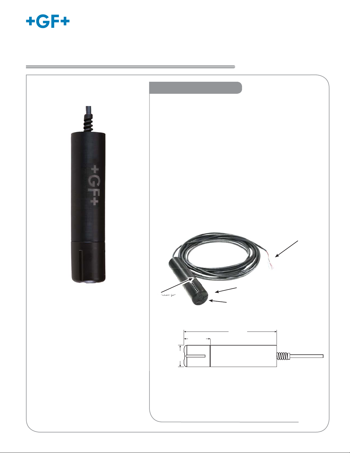
The RDO Pro system consists of the following:
English
Operator's Manual
• 10 m (32.8 ft.) cable with stripped and tinned ends
• Black sensor body with removable nose cone
• Optical DO sensing cap
• Titanium thermistor
Cable end, stripped and tinned
Nose cone
Thermistor
Sensor cap
(not visible)
Dimensions
20.3 cm
68.6 mm
(2.7 in.)
43.7 mm
(1.72 in.)
(8.0 in.)
Serial Numbers
The instrument part number, code number and serial number is
engraved on the side of the unit.
RDO is a registered trademark of In-Situ® Inc., Fort Collins, CO USA
Page 2
Introduction
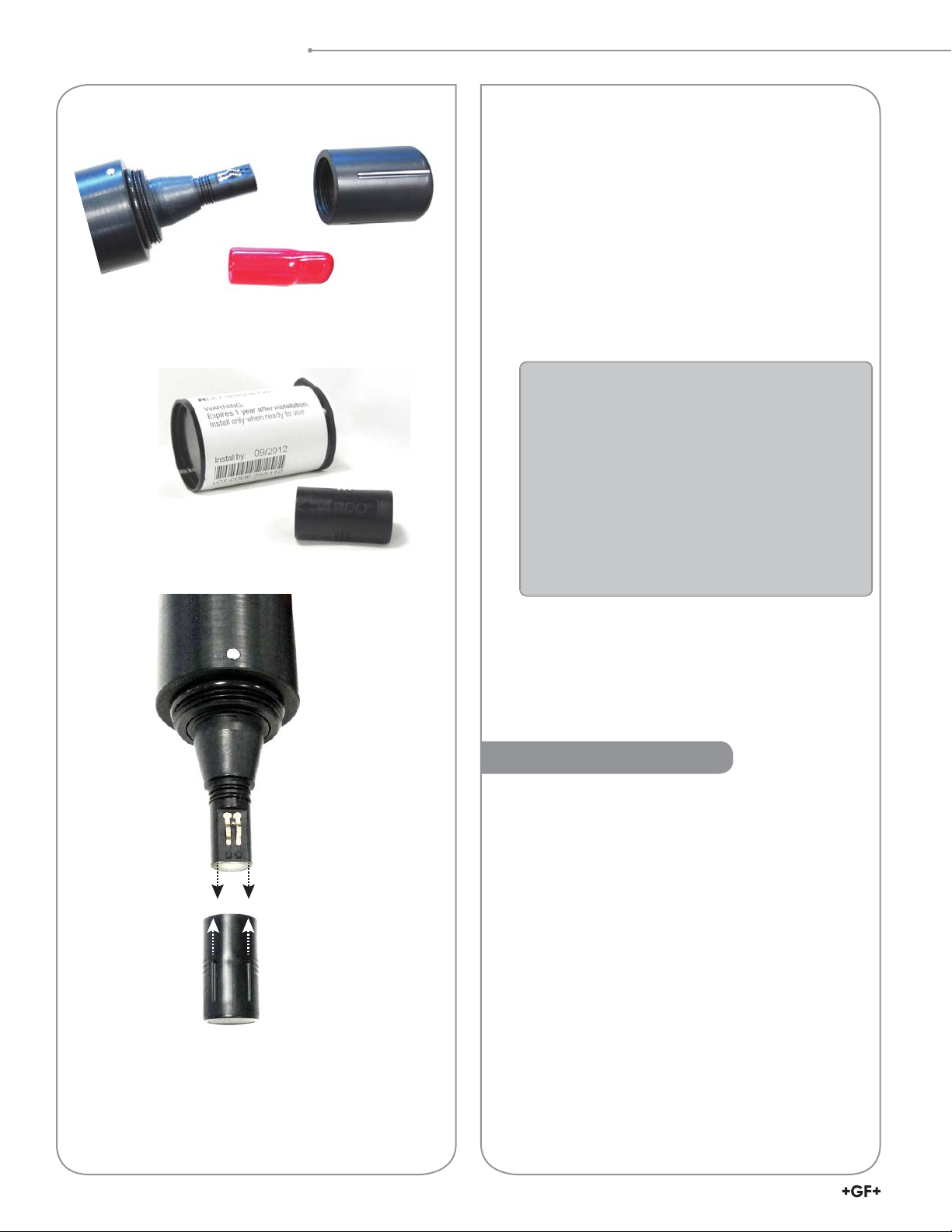
Unpacking the Sensor
Sensor
Shipping/Storage sleeve
Dust cap
Nose cone
1. Remove the RDO
®
sensor from the box and other
packaging materials.
2. Unscrew the nose cone from the sensor and
remove the red protective dust cap from the
sensor. Save the dust cap for later use.
3. Remove the sensor cap from its shipping/storage
sleeve.
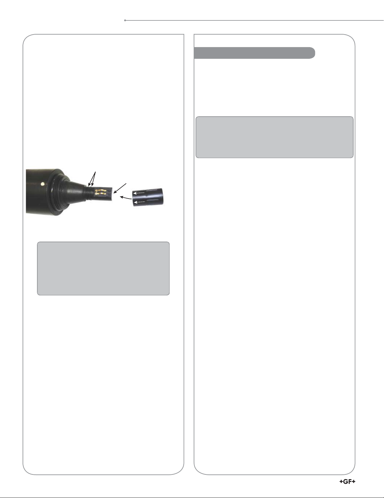
4. Align the two lines on the cap with the fl at part of
the sensor and fi rmly press (DO NOT TWIST) the
cap onto the sensor until it seals over the probe
body.
• CAUTION: Twisting the sensor cap can
permanently damage both the cap and the
sensor.
• Avoid allowing moisture, including atmospheric
humidity, inside the cap. Keep the cap in its
sealed packaging until you are ready to install
it. Install promptly. Make sure that O-ring
grooves are dry and the O-ring is not rolled or
pinched inside the cap.
• The cap's lifetime is 1 year after the fi rst
reading has been taken. Install by the date
printed on the packaging.
Align flat side of the tip
with lines on cap
5. Reattach the nose cone
Calibration
Calibration is not required. The unit, as shipped from
the factory, will measure within 2% of reading for the
life of the sensor cap.
Replacing the sensor cap will keep the reading within
2% accuracy.
2
2610 DO Sensor
Page 3
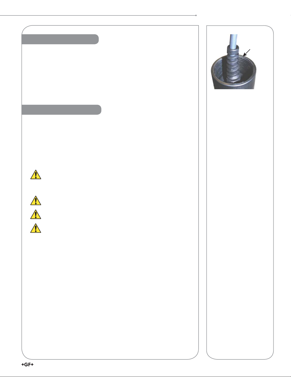
Sensor Deployment
The cable end of the RDO® Pro is internally threaded (1¼ - 11½ NPT) and can
be attached to a externally threaded pipe.
When deployed, make sure that the nose cone and thermistor are completely
submerged.
Care and Maintenance
Cleaning the Sensor Cap
1. Leave the cap and nose cone on the sensor!
2. Rinse the sensor with clean water from a squirt bottle or spray bottle.
3. Gently wipe with a soft-bristled brush or soft cloth if biofouling is present.
Use Alconox® to remove grease.
4. If extensive fouling or mineral build-up is present, soak the cap end in
vinegar for 15 min., then soak in deionized water for 15 min.
Sensor Deployment
1¼ in. NPT
with 10 m cable
Do not use organic solvents - they will damage the foil.
Do not remove the cap from the sensor prior to brushing.
Cleaning the Optical Window
Perform only when changing the cap. See full instructions in the sensor
replacement cap kit.
Do not wet the lens area with water or any solution.
Remove the cap and gently wipe the window with the supplied lens wipe.
Use only the supplied lens wipe for cleaning. Do not use any other wipe
or material.
Cleaning the Sensor Body
With the sensor cap installed on sensor, gently scrub sensor body with a softbristled brush or nylon dish scrubber. Use Alconox to remove grease or other
matter. Soak in vinegar and deionized (DI) water to remove mineral deposits or
extensive fouling as in step 4, above.
Cap Storage
• Prior to installation: Store in factory supplied container.
• Installed: Keep or store in the calibration chamber with the storage cap
attached and a few drops of clean water.
32610 DO Sensor
Page 4
Care and Maintenance
Sensor Cap Replacement
Replace the Sensor Cap
The sensor cap has a 1-year life after the instrument
takes its fi rst reading. Install the cap by the date
printed on the package. Replacement caps are
available from Georg Fischer, part number 3-2610.392
(159 310 122).
Avoid allowing moisture, including atmospheric humidity,
inside the cap. Keep the cap in its sealed package until
you are ready to install it. Install promptly. Make sure
that O-ring grooves are dry and that the O-rings are not
rolled or pinched inside the cap.
Lightly coat with lubricant
Install 2 O-rings
Clean lens and allow to dry
Replace cap in
a dry environment
Sensor Cap Replacement Kit Contents:
• Sensor cap
• O-rings (2)
• O-ring lubricant
• Lens wipe
• Instruction sheet
1. Pull the used sensor cap off of the sensor. DO
NOT TWIST!
2. Remove the existing O-rings from the sensor.
3. Use a lint-free cloth to remove any moisture from
the sensor body. NOTE: Make sure that the O-ring
grooves are dry. Avoid touching or cleaning the
lens with anything other than the supplied lens
wipe.
4. Use your fi nger to apply a thin layer of lubricant
around the O-ring grooves. Place the O-rings on
the sensor. NOTE: Do not transfer lubricant to the
lens or sensor pins.
5. Clean the lens on the sensor with the wipe
provided in the kit and allow to dry thoroughly.
Inspect for scratches or dirt.
6. Remove the new cap from its sealed package.
7. Align the arrow on the cap with the index mark on
the sensor and press it fi rmly until it seals over the
probe body. DO NOT TWIST. Make sure that the
O-rings are not pinched or rolled between the cap
and sensor.
8. Replace the nose cone on the sensor.
4
2610 DO Sensor
Page 5

Wiring and Set Up
Wiring and Set Up
3-2610-31 to 8900 Set Up
1. Connect the 8058, 2610-31, and 8900 as shown in the diagram.
2. Press and hold ENTER key for 5 seconds.
3. The display should fl ash “System Setup”.
4. Press ENTER key.
5. Scroll to the desired channel for Dissolved
Oxygen.
6. Press the ► key.
7. Enter the password.
8. Repeatedly press the ▼ key until the lower
line of the display reads “Other (4-20)”.
9. Press ENTER key.
10. The 8900 will warn that “Channel Data will
be Reset. Are you sure?” Press the ▼ key
so that “Yes” is fl ashing and press ENTER
key.
11. Simultaneously press the▲ and ▼ keys to
return to the Menu Directory.
12. Press the ▼ key to select the “Channel
8900 Sensor Inputs
6
7
BLACK (5 VDC)
8
RED (S
9
WHITE (GND)
10
11
12
13
14
3
L)
8058-2
+GF+ SIGNET
3 2 1
6 5 4
Loop1
PWR
Loop2
PWR
S L
DATA
N/C
7 8 9
3
Settings” menu and press ENTER key to
select.
13. Use the ▼ key to select the channel used
in step 5.
14. Press the ► key to change the label and press ENTER when done.
15. Press the ▼ key to select the
abbreviation.
16. Press the ► key to change the
label and press ENTER when
done. Press the ▼ key to select
the Units.
Regulated
Power Supply
24 VDC
V–
V+
BLACK
SHIELD
(no connection)
RED
4-20 mA
Input
4-20 mA input S3L Output
17. Press the ► key to change
the Units. The 2610 shipped
with default units of mg/L or
ppm, either can be used. Press
ENTER when completed.
DO Sensor
3-2610-31
GREEN
BLUE
WHITE
BROWN
No connection
18. Press the ▼ key to select the 4
mA Set Point.
19. Press the ► key to change the set point. By default the 4 mA set point for the 2610 is 0.0. Press the ENTER
key when complete.
20. Press the ▼ key to select the 20 mA Set Point.
21. Press the ► key to change the set point. By default the 20 mA set point for the 2610 is 20.0. Press the
ENTER key when complete.
22. Press the ▼ key to select the Decimal location.
23. Press the ► key and change the decimal position if desired. Press ENTER when complete.
24. Simultaneously press the ▲ and ▼ keys to exit out of the channel menu.
25. Continue programming other options in the 8900 or simultaneously press the ▲ and ▼ keys to return to the
View Mode.
+GF+
BLACK
BROWN
Signet 8058 i-Go™
4-20 mA to S
8058-1
BLACK
BROWN
RED
RED
BLACK
3
L Converter
DO
3-2610-31
No connection
DO
3-2610-31
No connection
+
24 VDC
Regulated
Power Supply
-
L
3
S
Output
(no connection)
Sensor
Sensor
BLACK
RED
WHITE
SHIELD
1
2
6
7
8
9
10
11
12
13
14
8900 Sensor Inputs
52610 DO Sensor
Page 6

Wiring and Set Up
3-2610-41 to 8900 Set Up
The 3-2610-41 Optical Dissolved Oxygen Sensor with S3L was designed to emulate a 4 to 20 mA current
input device, e.g., Signet 3-8058, on the 8900 controller. This allows the 3-2610-41 to be backward
compatible with all existing 8900 controllers.
1. Connect the 3-2610-41, and 8900 as shown in the diagram
NOTE: The wiring of the 3-2610-41 is non-standard:
• Red wire is connected to 12 to 24 VDC
• White wire is connected to S3L Data
• Black wire is connected to VDC Ground
• A jumper wire must be connected between the VDC Ground and S3L Gnd.
2. Press and hold Enter key for 5 seconds. The display will read “System Setup”.
3. Press Enter key.
4. Scroll to the channel that will be dissolved oxygen.
5. Press the ► key.
6. Enter the password.
7. Repeatedly press the ▼ key until the lower
3-2610-41
line of the display reads “Other (4-20)”.
8. Press Enter key.
9. The 8900 will warn that “Channel Data will
3-2610-41
be Reset. Are you sure?” press the ▼ key so
that “Yes” is fl ashing and press Enter key.
10. Simultaneously press the ▲ and ▼ keys to
return to the Menu Directory.
11. Press the ▼ key to select the menu “Channel
Settings” and press Enter key to select.
12. Use the ▼ key to select the channel used in
step 4.
13. Press the ► key to change the label and
press Enter when done.
14. Press the ▼ key to select the abbreviation.
15. Press the ► key to change the label and
press Enter when done.
16. Press the ▼ key to select the Units.
17. Press the ► key to change the Units. The
No Connection:
Green
Blue
Brown
I/O Module 3-8900.401-X
Frequency
Frequency
Input 2
Input
Input
Freq. Input (Red)
1
Freq. Input 2 (Red)
OR
S3L
Input
2
GND (White/Shield)
S3L
1
GND (White/Shield)
Analog Output 1
(if applicable)
Analog Output 2
(if applicable)
+5VDC (Black)
GND (Shield)
+5VDC (Black)
+5VDC (Black)
2610 shipped with default units of mg/L, or
ppm, either can be used. Press Enter when
completed.
18. Press the ▼ key to select the 4mA Set Point.
19. Press the ► key to change the set point. By default the 4mA set point for the 2610 is 0.0. Press the Enter key
when complete.
20. Press the ▼ key to select the 20mA Set Point.
21. Press the ► key to change the set point. By default the 20 mA set point for the 2610 is 20.0. Press the Enter
key when complete.
22. Press the ▼ key to select the Decimal location..
23. Press the ► key and change the decimal position if desired. Press Enter when complete.
24. Simultaneously press the ▲ and ▼ keys to exit out of the channel menu.
25. Continue programming other options in the 8900 or simultaneously press the ▲ and ▼ keys to return to
View Mode.
3
S L (Red)
3
S L (Red)
Channel 1
Channel 2
1
2
3
4
5
6
7
8
9
10
11
+
12
-
13
+
14
-
White
Black
Red
POWER
DC ONLY
SENSOR INPUTS
COMM PORT /
OUT 2 OUT 1
Red
Black
OUT 4 OUT 3
3-8900
V+
24 VDC
Regulated
V-
Power Supply
C
N
L
+
-
+
-
+
-
NO
NC
NO
NC
C
RELAY 2 RELAY 1
C
NO
NC
NO
NC
C
6
2610 DO Sensor
Page 7

3-2610-31 to 9900 Set Up
Wiring and Set Up
1. Wire the 9900, 2610-31, and 8058 as shown in the diagrams.
BLACK
RED
WHITE
SHIELD
9900 S3L Inputs9900 Power Inputs
SHLD
DATA
GND
V+
2. On the 9900 press and
hold the ENTER key for 2
seconds.
3. Press the ▼ key to select the
INPUT menu item.
4. Press the ENTER key to
access the INPUT menus.
5. Press the▲ key to select the
TYPE menu item.
6. Press the ► key to change
the TYPE selection.
7. Enter the password code.
8. Repeatedly press the ▼ key
until the “4-20 mA INPUT”
24 VDC
Regulated
Power Supply
DO Sensor
3-2610-31
PWR+
PWR–
LOOP+
LOOP–
V–
V+
BLACK
SHIELD
(no connection)
RED
BROWN
GREEN
BLUE
WHITE
4-20 mA
+GF+
Input
4-20 mA input S3L Output
No connection
Signet 8058 i-Go™
4-20 mA to S
8058-1
3
L Converter
3
Output
L
S
menu item is fl ashing and
then press the ENTER key.
9. The 9900 will prompt “All
settings will be reset”, press the
▲ key to select “Yes” and then press the ENTER key.
10. The 9900 will return to the View Mode display.
9900 Power Inputs
PWR+
PWR–
LOOP+
LOOP–
RED
BLACK
BROWN
DO
Sensor
3-2610-31
1
11. Press and hold the ENTER key for 2 seconds.
RED
BLACK
No connection
+
24 VDC
Regulated
Power Supply
-
12. Press the ▼ key to select the INPUT menu item.
13. In the NAME menu item, press the ► key to change the
displayed name from “4-20 mA INPUT” to a more descriptive
name (e.g., "DISSOLVED O2") and press ENTER when done.
14. Press the ▼ key to select SENSOR UNIT menu item.
15. Press the ► to change the label from UNIT to MG/L or PPM
and press ENTER.
16. Press the ▼ key and ensure the 4 mA VALUE is set to 0.0000.
17. Press the ▼ key and change the 20 mA VALUE from
9900 S
V+
8058-2
3
L Inputs
DATA
GND
SHLD
+GF+ SIGNET
3 2 1
6 5 4
Loop1
PWR
Loop2
PWR
DATA
N/C
7 8 9
3
S L
5.0000 to 20.000 and press ENTER.
18. Press both the▲ and ▼ keys simultaneously to return to
the Menu.
19. Press the ▼ to select the LOOP menu and press ENTER.
RED (S
BLACK (5 VDC)
3
L)
WHITE (GND)
20. Set the 4 MA SET POINT to your desired value. The 2610 is
factory set for a 0 to 20 mg/L output. Press ENTER when done.
21. Press the ▼ key to select the 20 MA SET POINT and set to your desired value. The 2610 is factory set for a
0 to 20 mg/L output. Press ENTER when done.
22. Press both the ▲ and ▼ keys simultaneously to return to the Menu.
23. Press the ▼ key twice to select the OPTION menu and press ENTER.
24. Press the ▼ key twice to select the SET BAR MIN option. Change this option if desired. The 2610 is factory
set for a 0 to 20 mg/L output. Press the ENTER key when done.
25. Press the ▼ key to select the SET BAR MAX option. Change this option if desired. The 2610 is factory set for
a 0 to 20 mg/L output. Press ENTER when done.
26. Press both the▲ and ▼ keys simultaneously to return to the Menu.
27. ENTER the other menus and set the unit as desired for your application.
28. Press both the▲ and ▼ keys simultaneously to return to the View Menu.
Technical Notes:
• The cable length from the 8058 to the 9900 must not exceed 60 m (200 ft).
• When using the 8058-2 with the 9900, connect the loop source to 8058-2 Channel 1 input
ONLY as shown in the fi gure.
• See the 8058 manual for more information.
72610 DO Sensor
Page 8

Wiring and Set Up
3-2610-41 to 9900 Set Up
The 3-2610-41 Optical Dissolved Oxygen Sensor with S3L was designed to emulate a 4 to 20 mA current input
device, 8058, on the 9900 controller. This allows the 3-2610-41 to be backward compatible with all existing 9900
controllers.
1. Wire the 9900 and 3-2610-41 as shown in the diagram.
9900 S3L Inputs
NOTE: The wiring of the 3-2610-41 is nonstandard:
• 3-2610-41 Red wire is connected to 12 to 24 VDC
• 3-2610-41 White wire is connected to S3L Data
• 3-2610-41 Black wire is connected to VDC Ground
• A jumper wire must be connected between the VDC
Ground and S3L Gnd.
2. On the 9900 press and hold the ENTER key for 2
seconds.
3. Press the ▼ key to select the INPUT menu item.
4. Press the Enter key to access the INPUT menus.
24 VDC
Regulated
Power Supply
V+
RED
BLACK
V-
SHIELD
RED
5. Press the ▲ key to select the TYPE menu item.
6. Press the ► key to change the
TYPE selection.
3-2610-41
7. Enter the code.
8. Repeatedly press the ▼ key until the “4-20 mA INPUT”
menu item is fl ashing and then press ENTER.
9. The 9900 will prompt “All settings will be reset”. Press the ▲ key to select “Yes” and then press ENTER.
10. The 9900 will return to the View Mode display.
11. Press and hold the ENTER key for 2 seconds.
12. Press the ▼ key to select the INPUT menu item.
13. In the NAME menu item, press the ► key to change the displayed name from “4-20 mA INPUT” to a more
descriptive name (e.g., "DISSOLVED O2") and press ENTER when done.
14. Press the ▼ key to select SENSOR UNIT menu item.
15. Press the ► to change the label from UNIT to MG/L or PPM and press ENTER.
16. Press the ▼ key and ensure the 4 mA VALUE is set to 0.0000.
17. Press the ▼ key and change the 20 mA VALUE from 5.0000 to 20.000 and press ENTER.
18. Press both the ▲ and ▼ keys simultaneously to return to the Menu.
19. Press the ▼ to select the LOOP menu and press ENTER.
20. Set the 4 MA SET POINT to your desired value. The 2610 is factory set for a 0 to 20 mg/L output. Press
ENTER when done.
21. Press the ▼ key to select the 20 MA SET POINT and set to your desired value. The 2610 is factory set for a 0
to 20 mg/L output. Press ENTER when done.
22. Press both the ▲ and ▼ keys simultaneously to return to the Menu.
23. Press the ▼ key twice to select the OPTION menu and press ENTER.
24. Press the ▼ key twice to select the SET BAR MIN option. Change this option if desired. The 2610 is factory
set for a 0 to 20 mg/L output. Press ENTER when done.
25. Press the ▼ key to select the SET BAR MAX option. Change this option if desired. The 2610 is factory set for
a 0 to 20 mg/L output. Press ENTER when done.
26. Press both the ▲ and ▼ keys simultaneously to return to the Menu.
27. Enter the other menus and set up the unit as desired for your application.
28. Press both the ▲ and ▼ keys simultaneously to return to the View Menu.
SHLD
DATA
GND
V+
9900 Power Inputs
RED
BLACK
WHITE
Blue
Green
No connection
Brown
PWR+
PWR–
LOOP+
LOOP–
9900 Generation III supports 3-2610-41 direct connection.
Please refer to the 9900 product manual for setup instructions.
8
2610 DO Sensor
Page 9

Wiring and Set Up
3-2610 to 4 to 20 mA Set Up
Red
Black
Brown
Green
Blue
White
OR
Programmable
Logic Controller
NOTE: The S
3-2610-31
or 3-2610-41
+ In
- In
Chart
Recorder
3
L and Modbus connectors can
be used simultaneously with the 4 to 20 mA.
3-2610 to Modbus Set Up
3-2610-31
or 3-2610-41
NOTE: The S
be used simultaneously with the 4 to 20 mA.
Modbus programming manual is available
on the web at www.gfsignet.com.
3
L and Modbus connectors can
Red
Black
Blue
Green
Brown
White
No connection
+ In
PLC
No connection
Programmable Logic Controller
Regulated
+
Power Supply
–
12 to 24 VDC
4 to 20 mA
Input
- In
Regulated
+
Power Supply
–
12 to 24 VDC
+
Modbus
RS485
PLC
–
Modbus
RS485
or
Other Modbus Master
92610 DO Sensor
Page 10

Notes
10
2610 DO Sensor
Page 11

Specifi cations
General
Sensor type: .....................................Luminescent dissolved oxygen sensor
Transmitter/local display: ..................Optional, not required
Communications options: .................Modbus (RS-485), 4 to 20 mA, Digital S3L
Maximum cable length:.....................Up to 4000 ft (Modbus and 4 to 20 mA)
Up to 100 ft (S3L)
Internal mounting thread:..................1¼ NPT
Performance
Salinity range: ...................................0 to 42 PSU, fi xed or real-time capable
pH range: ..........................................2 to 10 pH
Barometric range: .............................507 to 1115 mbar, fi xed or real-time capable
Idle current:.......................................160 μA typical at 24 VDC
Maximum pressure: ..........................300 psi
Range: ..............................................0 to 20 mg/L concentration, 0 to 200% saturation
Accuracy (DO): .................................±0.1 mg/L, 0 to 8 mg/L,
±0.2 mg/L, 8 to 20 mg/L
Response time:.................................Cap T90: 30 sec
Cap T95: 37 sec @ 25 °C
Resolution:........................................0.01 mg/L
Measure current: ..............................6 mA typical at 24 VDC
Specifi cations
Environmental
Wetted Materials: ..............................ABS, Titanium, FPM
Usage life of cap: ..............................1 year from the fi rst instrument reading
Shelf life of cap: ................................24 months from date of manufacture (install w/in 12 mo. of manufacture)
Operating temperature: ....................0 °C to 50 °C (32 °F to 122 °F)
IP rating: ...........................................IP-67 with cap off, IP-68 with cap installed
Storage conditions, cap: ...................1 °C to 60 °C (33 °F to 140 °F), in factory container
Storage conditions, sensor: ..............-5 °C to 60 °C (23 °F to 140 °F)
Warranty
Sensor: .............................................3 years from date of manufacture
Cap: ..................................................2 years from date of manufacture or one year from fi rst reading
whichever comes fi rst
Standards and Approvals
CE
RoHS Compliant
China RoHS (Go to www.gfsignet.com for details)
This device complies with Part 15 of the FCC rules. Operation is subject to the following two conditions:
(1) This device may not cause harmful interference, and, (2) This device must accept any interference
received, including interference that may cause undesired operation.
112610 DO Sensor
Page 12

Ordering Information
Ordering Information
2610 Optical DO Sensor
Mfr. Part No Code Description
3-2610-31 159 001 753 Optical DO Sensor (0-20 ppm) with Modbus, SDI, and 4 to 20 mA output
3-2610-41 159 001 754 Optical DO Sensor (0-20 ppm) with S3L, Modbus, and 4 to 20 mA output
Accessories and Replacement Parts
Mfr. Part No Code Description
3-2610.392 159 310 122 Replacement Optical Dissolved Oxygen Sensor Cap (0 to 20 ppm)
3-2610.501 159 500 413 DO Threaded Pipe Adapter, 2 in. Male NPT
861-170 –– 1¼ in. Close Nipple
–– 721 914 211 63 mm Cement Socket to 2 in. NPT Female Adapter Fitting
Georg Fischer Signet LLC, 3401 Aero Jet Avenue, El Monte, CA 91731-2882 U.S.A. • Tel. (626) 571-2770 • Fax (626) 573-2057
For Worldwide Sales and Service, visit our website: www.gfsignet.com • or call (in the U.S.): (800) 854-4090
For the most up-to-date information, please refer to our website at www.gfsignet.com
3-2610.090 Rev. C 08/13 English © Georg Fischer Signet LLC 2013
 Loading...