

Page 1
½ in. NPT conduit port
Use 2-conductor shielded cable for cable extensions up to 300m (1000 ft.)
Maintain cable shield through splice.
Black (5 to 24 VDC)
Silver (DC return)
Signet Instruments
Other Brands
Input
Gnd.
10 kΩ
+
5 to 24
VDC
-
black
silver
red
pull-up resistor required (10 kΩ recommended).
Use 2-conductor shielded cable for cable extensions up to 300m (1000 ft.)
Maintain cable shield through splice.
Other
instrument
Blk, sensor
power
Red, freq.
input
Shld,
Gnd
instrument
Red (signal out)
Signet 2540 High Performance Flow Sensor
*3-2540.090*
3-2540.090 Rev. F 11/12 English
For the most up-to-date information, please refer to our website at www.gfsignet.com
SAFETY INSTRUCTIONS
1. Do not remove from pressurized lines.
2. Do not exceed maximum temperature/pressure specifi cations.
3. Wear safety goggles or faceshield during installation/service.
4. Do not alter product construction.
5. Apply sealant or PTFE tape to sensor threads, inspecting threads to ensure integrity.
Do not install a sensor with damaged threads.
Pipe fi ttings MUST be installed by a certifi ed welder only. Signet will not assume liability of any kind for improper fi tting
installations.
2540 Hot-Tap sensor specifi cations and limitations depend on the lowest maximum rating of the components associated
with the system. For example, if a ball valve in the system is rated at a maximum 100 psi @ 175°F, you must limit the entire
system's maximum pressure/temperature rating to 100 psi @ 175°F. All higher maximum specifi cations MUST yield to the
component with the lowest maximum specifi cation.
Maximum Operating Pressure/Temperature:
• 17 bar (250 psi) @ 82°C (180°F) with standard FPM sensor fi tting O-rings.
• 17 bar (250 psi) @ 100°C ( 212°F) with optional EPDM sensor fi tting O-rings.
Note: Pressure/temperature specifi cations refer to sensor performance in water. Certain chemical limitations may apply.
Chemical compatibility should be verifi ed.
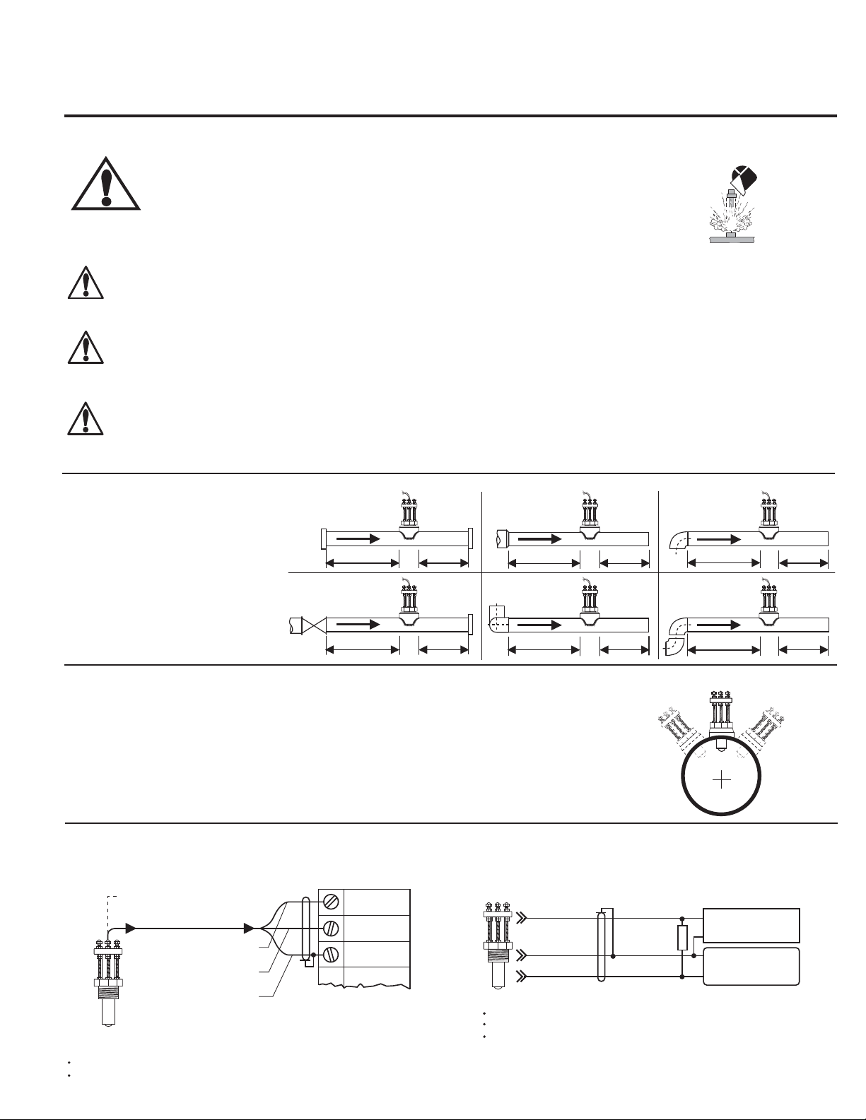
English
Inlet
1. Location of Fitting
Recommended sensor upstream/
downstream
mounting requirements.
Flange
10x I.D. 5x I.D.
Outlet
Reducer
2 x 90° Elbow
3 dimensions
Valve/Pump
50x I.D. 5x I.D.
2. Sensor Mounting Position
Vertical mounting is recommended for best overall performance. Mount at a maximum of 30°
when air bubbles are present. DO NOT mount on the bottom of the pipe when sediments are
present.
3. Sensor Wiring
15x I.D. 5x I.D.
40x I.D. 5x I.D.
2 x90° Elbow
-
30°
90° Elbow
20x I.D. 5x I.D.
25x I.D. 5x I.D.
0°
+30°
Process Pipe
Page 2
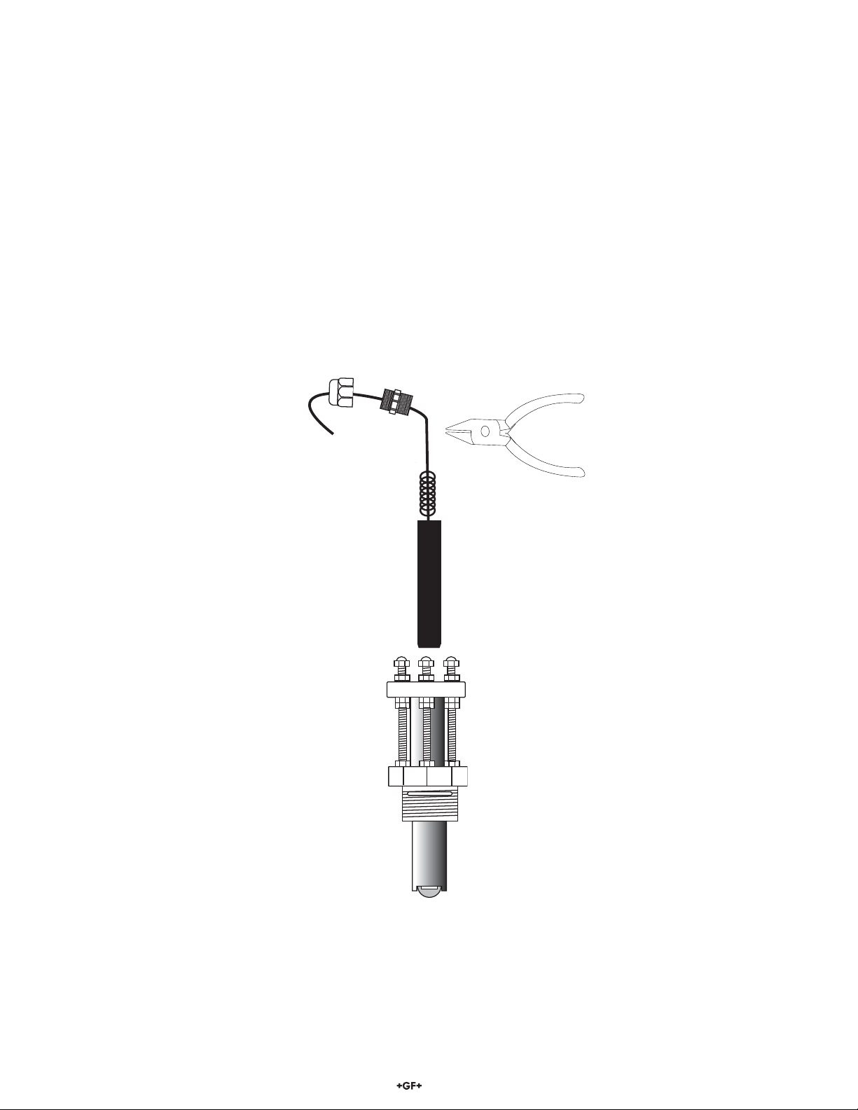
4. Electronics Module Installation and Removal
The electronics module of this sensor can be replaced without removing the steel sensor body from the line.
1. Loosen liquid tight connector cap.
2. Loosen liquid tight connector compression fi tting from sensor body.
3. Grasp the electronics at the rubber strain relief (do not pull on cable) and pull fi rmly.
To reinstall the electronics module:
• Insert module into sensor housing, making sure module is fully seated.
The tip of the electronic module must bottom-out in the sensor housing.
• Replace the liquid tight connector assembly.
NOTE: Apply thread sealant to the liquid tight connector threads.
To install the cable inside protective conduit, remove the liquid tight connector completely. Thread ½ in. conduit into top of sensor body.
Liquid Tight Connector-Cap
½ in. NPT Threads
Liquid Tight ConnectorCompression Fitting
w/ ½ in. NPT threads
Electronics Module
3-2541.260-1 (for Standard sensor)
3-2541.260-2 (for Hot-tap sensor)
NOTE: Apply thread sealant to the
liquid tight connector threads.
Grip the electronics
module at rubber strain
relief
2
2540 High Performance Flow Sensor
Page 3
5. Installation
pipe
fitting
process
pipe
pipe sealant recommended
sensor
fitting
The following items are required to properly install Signet 2540 Sensors.
5.1 Hardware, Standard Sensor
• Female pipe fi tting (weld-on or saddle) with 1½ in. NPT or ISO 7-Rc 1½ threads
• 32 mm (1¼ in.) diameter drill
• Pipe thread sealant
• Tape measure
5.2 Hardware, Hot-Tap Sensor
The Hot-Tap sensor requires all the standard sensor items plus:
• Hot-Tap drilling machine (e.g., Mueller drilling machine or equivalent)
• Female ball or gate valve (full port only) with 1½ in. NPT or ISO 7-Rc 1½ threads
• Male pipe nipple, 32 x 50 mm (1½ x 2 in.) with 1½ in. NPT or ISO 7-R 1½ threads
• Hot-Tap installation tool (purchased separately)
5.3 Standard Fitting Installation
A. Depressurize and drain pipe.
B. Wearing safety face protection, drill a 32 mm (1¼ in.) diameter hole in the
pipe.
C. Install the pipe fi tting of the outside of the pipe according to the manufacturer's
instructions. Failure to follow these instructions may result in serious bodily
injury and/or product failure.
D. Remove sensor fi tting from sensor assembly.
E. Thread sensor fi tting into pipe fi tting. (Fig. 1)
Fig. 1
5.4 Hot-Tap Fitting Installation
A. Install the pipe fi tting on the outside diameter of the pipe according to the manufacturer's instructions. Failure to follow these
instructions may result in serious bodily injury and/or product failure.
B. Install the pipe nipple and isolation valve (ball or gate valve) onto the external pipe fi tting using pipe sealant on the
threads. (Fig. 2)
C. Wearing safety face protection, install an appropriate hole cutting tool per manufacturer's instructions (e.g., Mueller
drilling machine) with a 32 mm (1.25 in.) drill onto the top of the isolation valve, ensuring a tight fi t. Use the
recommended drill bit size or damage to the isolation valve may occur.
D. Open the isolation valve and insert the drill through the valve and cut the sensor clearance hole. After the hole is cut, withdraw the
drill from the isolation valve and close the valve. Remove the drilling machine per manufacturer's instructions. (Fig. 3)
E. Install the sensor fi tting/bleed valve into the top of the isolation valve. Make sure the bleed valve clears the handle of the isolation
valve during operation.
customer supplied
ball or gate valve
sensor fitting
bleed valve
Fig. 2
2540 High Performance Flow Sensor
customer supplied
nipple: 32 x 50 mm
(1.25 x 2 in.) long
process pipe (side view)
Fig. 3
process pipe
make sure
bleed valve
clears isolation
valve handle
3
Page 4
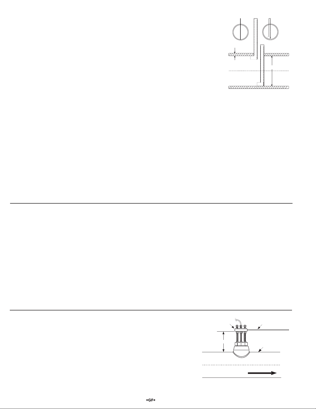
5.5 Calculating the H Dimension
A
B
1
2
3
4
5
6
1
2
3
4
5
A
B
1
2
3
4
5
6
1
2
3
4
5
pipe I.D.
wall
A
B
1
2
3
4
5
6
1
2
3
4
5
incorrect
correct
Before installing the sensor some critical dimensions must be established (for Hot-Tap installations,
we assume the pipe dimensions are known). The rotor shaft must be located 10% inside the pipe I.D.
to ensure accurate calibration capability. To accomplish this, the "H" dimension is measured from the
outside surface of the pipe to the bottom of the sensor fl ange.
Nominal "H" dimensions for standard pipes are listed here. For non-standard pipe dimensions, calculate
the "H" dimension using the formula listed below. The wall thickness and inside diameter (I.D.) are
required for the "H" dimension calculation.
The 6 inch ruler (included) may be used to measure your pipe I.D. and wall thickness up to 5 inches
(standard sensors only).
Pipe wall thickness: __________ Pipe I.D.: ___________
H Dimensions, Standard Sensors (2540-1, 2540-2)
Wrought Steel Pipe Per ANSI 36.10
NPS SCH 40 SCH 80 STD XS
inches inches inches inches inches
1½ 4.924 4.880 4.924 4.880
2 4.869 4.818 4.869 4.818
2½ 4.780 4.722 4.780 4.722
3 4.707 4.640 4.707 4.640
3½ 4.649 4.576 4.649 4.576
4 4.590 4.510 4.590 4.510
5 4.467 4.374 4.467 4.374
6 4.344 4.222 4.344 4.222
8 4.110 3.968 4.110 3.968
10 3.863 3.680 3.863 3.755
12 3.630 3.405 3.655 3.555
14 3.480 3.230 3.530 3.430
16 3.230 2.955 3.330 3.230
18 2.980 2.680 3.130 3.030
20 2.755 2.405 2.930 2.830
22 ----- 2.130 2.730 2.630
24 2.280 1.855 2.530 2.430
H Dimensions, Hot-Tap Sensors (2540-3, 2540-4)
Wrought Steel Pipe Per ANSI 36.10
NPS SCH 40 SCH 80 STD XS
inches inches inches inches inches
1 ½ 15.084 15.040 15.084 15.040
2 15.029 14.978 15.029 14.978
2 ½ 14.940 14.882 14.940 14.882
3 14.867 14.800 14.867 14.800
3½ 14.809 14.736 14.809 14.736
4 14.750 14.670 14.750 14.670
5 14.627 14.534 14.627 14.534
6 14.534 14.382 14.534 14.382
8 14.270 14.128 14.270 14.128
10 14.023 13.840 14.023 13.915
12 13.790 13.565 13.815 13.715
14 13.640 13.390 13.690 13.590
16 13.390 13.115 13.490 13.390
18 13.140 12.840 13.290 13.190
20 12.915 12.565 13.090 12.990
22 ----- 12.290 12.890 12.790
24 12.440 12.015 12.690 12.590
(-----) unavailable
Stainless Steel Pipe Per ANSI B36.19
NPS SCH 5S SCH 10S SCH 40S SCH 80S
inches inches inches inches inches
1½ 4.988 4.953 4.924 4.880
2 4.940 4.905 4.869 4.818
2½ 4.876 4.847 4.780 4.722
3 4.814 4.784 4.707 4.640
3½ 4.764 4.734 4.649 4.576
4 4.714 4.684 4.590 4.510
5 4.586 4.567 4.467 4.374
6 4.480 4.460 4.344 4.222
8 4.280 4.249 4.110 3.968
10 4.048 4.023 3.863 3.755
12 3.830 3.811 3.655 3.555
14 3.705 3.680 ----- ----16 3.498 3.480 ----- ----18 3.298 3.280 ----- ----20 3.080 3.056 ----- ----22 2.880 2.856 ----- ----24 2.656 2.630 ----- -----
(-----) unavailable
Stainless Steel Pipe Per ANSI B36.19
NPS SCH 5S SCH 10S SCH 40S SCH 80S
inches inches inches inches inches
1 ½ 15.148 15.113 15.084 15.040
2 15.101 15.065 15.029 14.978
2 ½ 15.036 15.007 14.940 14.882
3 14.974 14.944 14.867 14.800
3 ½ 14.924 14.894 14.809 14.736
4 14.874 14.844 14.750 14.670
5 14.747 14.727 14.627 14.534
6 14.640 14.620 14.534 14.382
8 14.440 14.409 14.270 14.128
10 14.208 14.183 14.023 13.915
12 13.990 13.971 13.815 13.715
14 13.865 13.840 ----- ----16 13.658 13.640 ----- ----18 13.458 13.440 ----- ----20 13.240 13.216 ----- ----22 13.040 13.016 ----- ----24 12.816 12.790 ----- -----
Standard Sensors: H = 5.23 - wall thickness - (0.10 x I.D.)
Hot-Tap Sensors: H=15.39 in. - wall thickness - (0.10 x I.D.)
Example: 3.0 inch schedule 80 wrought steel
Wall thickness = 0.3 in. / Inside diameter = 2.9 in.
H = 5.23 - 0.3 - (0.10 X 2.9) / H = 117.86 mm (4.64 in.)
Record your sensor's "H" dimension for future reference: H= ___________
After correct dimensions are calculated and recorded, the sensor can be installed in the
fi tting. The Standard and Hot-Tap versions require substantially different procedures.
4
sensor flange
"H"
pipe side view
alignment rod
process pipe
direction
of flow
2540 High Performance Flow Sensor
Page 5

lower hex nuts
(3/16 x 1/4-20)
jam nuts
(5/32 x 1/4-20)
359 mm
(14.14 in.)
sensor
fitting
UNDER PRESSURE!
sensor fitting
hex nut
Lock washer
5.6 Standard Sensor Installation
sensor fitting
hex nut
Lock washer
A. Thread one hex nut onto each of the three threaded rods
included in package. Install threaded rod with a lock washer
Fig. 4
onto the sensor fi tting. Secure rods in place by tightening each
hex nut against the sensor fi tting. (Fig. 4)
B. Thread one jam nut and lower hex nut onto each threaded
rod so that the top surface of each nut is at the proper "H"
dimension for your pipe. Secure each hex nut with a jam nut.
(Fig. 5)
C. Insert the fl ow sensor into the sensor fi tting, making sure the
alignment hole on the sensor fl ange is pointing downstream.
D. Place the alignment rod in the alignment hole
on the sensor fl ange. Align the fl ange so rod is
parallel to the process pipe. (Fig. 6)
E. Thread upper hex nuts with lock washers until they
contact the sensor fl ange and tighten. Check for
proper "H" dimension and readjust if necessary.
(Fig. 7)
sensor
flange
flow direction
alignment
rod
process pipe
(top view)
The flow sensor alignment rod MUST be
parallel to the process pipe as shown.
Fig. 6
5.7 Hot-Tap Sensor Installation
A. Thread one hex nut onto each of the three threaded rods included in package. Install threaded
rod with a lock washer onto the sensor fi tting. Secure rods in place by tightening each hex nut
against the sensor fi tting. (Fig. 8)
Fig. 5
"H"
"H"
sensor
flange
jam nuts
sensor
fitting
Fig. 7
FLOW
lower hex nuts
(3/16 x 1/4-20)
jam nuts
(5/32 x 1/4-20)
hex nut &
lock washer
sensor fitting
process pipe
cap nuts
upper hex nuts
& lockwashers
lower hex nuts
female pipe fitting
process
pipe wall I.D.
B. Thread one jam nut and lower hex nut onto each threaded rod so that the top surface of each
nut is 359 mm (14.14 in.) from the top surface of the sensor fi tting. Secure each hex nut with
a jam nut. (Fig. 9)
CAUTION: This setting is critical to ensure an adequate sensor seal and to
prevent the rotor from hitting the isolation valve orifi ce during installation.
C. Wipe the sensor body with a dry, clean cloth. Orient the alignment hole on the sensor fl ange
to point downstream. Place the slotted fl ange over the threaded rods. Lower the sensor into
the fi tting until the sensor fl ange rests on the lower hex and jam nuts.
D. Secure the sensor with lock washers and upper hex nuts on the top of the fl ange. Before
tightening, align the sensor fl ange so that the alignment rod is parallel and level with the
process pipe. (Fig. 10 & Fig. 11)
E. Make sure the bleed valve is closed (full clockwise position).
sensor
flange
flow direction
alignment
rod
process pipe
(top view)
The flow alignment rod MUST be
parallel to the process pipe as shown.
sensor flange
lower hex nut
and jam nuts
18 inch
threaded rods
sensor
fitting
Fig. 8
Upper hex nuts
(3/16 x 1/4-20)
1/4 in. lock
washers
alignment rod
359 mm (14.14 in)
bleed valve
Fig. 9
2540 High Performance Flow Sensor
Fig. 10
Fig. 11
direction
of flow
process pipe (side view)
5
Page 6

Hot-Tap Sensor Installation - Continued
F. Thread protector plate hex nuts onto each of the three
threaded rods. Adjust each hex nut to a height of
approximately 25 mm (1 in.) from the top of each rod. (Fig. 12)
protector plate
cap nuts
25 mm
(1.0 in.)
protector plate
removed during
sensor installation
protector plate
hex nut (3/16 x ¼ -20)
Fig. 12
G. Position the installation tool bearing plate by rotating it so that it is approximately 40 mm (1.6 in.) from the swivel mount. Mount
the installation tool by placing the threaded rods through the holes in the tool's bearing plate, resting the bearing plate on top of
the protector plate hex nuts. Make sure the swivel mount's ears are mounted between the threaded rods (not over the rods).
Install the bearing plate cap nuts. Tighten the bearing plate cap nuts to secure the installation tool in place. (Fig. 13)
H. Align the sensor cable with the swivel mount cable port to prevent cable pinching. Use a 3/8 inch wrench or socket to turn the
installation tool shaft clockwise until it is seated in the hole at the top of the sensor fl ange.
I. Wearing safety face protection, slowly open the isolation valve to the full open position. Loosen the lower hex and
jam nuts and move them to the proper "H" dimension. Turn the installation tool shaft clockwise until the sensor fl ange
contacts the lower hex and jam nuts. Thread the upper hex nuts down until they contact the sensor fl ange. Tighten the
upper hex nuts to secure the sensor. (Fig. 14)
J. Remove cap nuts and withdraw the installation tool. Be careful to not damage cable. Replace protector plate and cap nuts.
(Fig. 15)
Fig. 14
Fig. 13
cap nuts
protector plate
hex nuts
sensor
cable
installation tool
threaded shaft
bearing plate
swivel mount
w/cable port
sensor flange
installation
tool shaft
upper hex nuts
"H"
cap nuts
alignment rod
lower hex nuts
jam nuts
isolation valve
Fig. 15
protector plate
cap nuts
protector plate
protector plate
sensor body
hex nut
direction
of flow
6. Standard Sensor Removal
To remove the sensor from a depressurized empty pipe, simply remove the cap nuts and upper hex nuts located above the sensor
fl ange. Pull up on sensor fl ange with twisting motion.
6
2540 High Performance Flow Sensor
Page 7

installation tool
threaded shaft
process pipe (side view)
372 mm
(14.6 in.)
upper hex nuts
and lock washers
sensor flange
lower hex and
jam nuts
UNDER PRESSURE!
sensor fitting
isolation valve
7. Hot-Tap Sensor Removal
Punch
Retainer
To remove the Hot-Tap sensor safely from a pressurized active pipe, the entire installation
process must be reversed.
A. Remove the cap nuts, protector plate and protector plate hex nuts. (Fig. 16)
B. Thread installation tool in place and secure bearing plate in place of sensor protector plate.
(Fig. 17)
C. Turn shaft of installation tool clockwise to lower tool into opening in sensor fl ange. Guide
cable into the port to prevent damage.
protector plate
Fig. 16
cap nuts
protector plate
protector plate
hex nut
Fig. 17
D. Wearing safety face protection, loosen the upper hex nuts and raise to 372 mm (14.6 in.) from top of sensor fi tting to
bottom of upper hex nuts/lock washers. CAUTION! This measurement is critical to maintain watertight seal in
sensor while allowing clearance to close the isolation valve.
E. Wearing safety face protection, turn the installation tool shaft
counterclockwise to withdraw sensor until the sensor fl ange contacts
the upper hex nuts. (Fig. 18)
F. Raise one lower hex and jam nut to bottom of sensor fl ange.
G. Close isolation valve, remove bearing plate and tool.
H. Wearing safety face protection, cover the bleed valve with suitable
protection (rag, towel, etc.) and open the bleed valve (ccw rotation)
to relieve internal pressure. Pull sensor up until bleed valve purges
some fl uid (indicating sensor is past 1st o-ring seal inside sensor
fi tting).
CAUTION: In case of a leaky isolation valve, the sensor will be under a slight
cap nuts
protector plate
hex nuts
upper hex nuts
Fig. 18
installation tool
threaded shaft
installation tool
bearing plate
swivel mount
w/cable port
sensor flange
1 lower hex nut
and jam nut
sensor body
amount of pressure. Care should be taken when removing the sensor.
Use the bleed valve to relieve this pressure taking care not to spray fl uid on yourself or others.
Sensor can now be safely removed. When reinstalling the sensor: leave one lower hex nut in position to guide sensor to proper
isolation valve clearance height before opening isolation valve. Return to "H" dimension height after valve is opened.
8. Maintenance
Your sensor requires little or no maintenance of any kind, with the exception of an occasional sensor/paddlewheel cleaning.
Rotor Replacement Procedure
1. With a small pair of needle-nose
2. Remove retainer from each side by
2540 High Performance Flow Sensor
pliers, fi rmly grip the center of the
rotor pin (axle) and with a twisting
motion, bend the rotor pin into an
"S" shape. This should pull the
ends of the pin out of the retainers
and free the rotor assembly.
gently tapping it inwards using a punch.
Install a new retainer with its rotor pin
clearance hole inward. Only install one
retainer at this time.
Rotor Pin
3. Insert the new rotor assembly
and bearings into the rotor
housing of the sensor and
place the new rotor pin (axle)
through the open end of
the rotor housing, through
the rotor and bearings, and
into the previously installed
retainer.
4. Using a vise or C-clamp, press
the second retainer into the hole
in the sensor body while lining
up the rotor pin with the center
of the retainer hole.
Note: A hammer and center
punch can also be used if a
clamp or vise is not available.
Existing
Retainer
Rotor Pin
New
Bearings
Rotor
Assembly
7
Page 8

9. K-Factors (Stainless Steel, Wrought Steel & Plastic Pipe)
SCH 5S STAINLESS STEEL PIPE
PER ANSI B36.19
K-Factor K-Factor
PIPE PULSES/ PULSES/
SIZE U.S. GAL LITER
1½ in. 115.1900 30.433
2 in. 71.3960 18.863
2 ½ in. 49.263 13.015
3 in. 32.636 8.622
3 ½ in. 24.537 6.483
4 in. 19.1350 5.055
5 in. 12.4490 3.289
6 in. 8.4602 2.235
8 in. 4.9137 1.298
10 in. 3.1228 0.825
12 in. 2.1772 0.575
14 in. 1.7977 0.475
16 in. 1.3717 0.362
18 in. 1.0855 0.287
20 in. 0.8801 0.233
22 in. 0.7293 0.193
24 in. 0.6141 0.162
SCH 10S STAINLESS STEEL PIPE
PER ANSI B36.19
K-Factor K-Factor
PIPE PULSES/ PULSES/
SIZE U.S. GAL LITER
1½ in. 127.930 33.799
2 in. 76.439 20.195
2 ½ in. 51.946 13.724
3 in. 34.174 9.029
3½ in. 25.571 6.756
4 in. 19.829 5.239
5 in. 12.730 3.363
6 in. 8.5938 2.270
8 in. 5.0062 1.323
10 in. 3.1793 0.840
12 in. 2.1914 0.579
14 in. 1.8147 0.479
16 in. 1.3798 0.365
18 in. 1.0912 0.288
20 in. 0.8855 0.234
22 in. 0.7334 0.194
24 in. 0.6175 0.163
XS WROUGHT STEEL PIPE
PER ANSI B36.10
K-Factor K-Factor
PIPE PULSES/ PULSES/
SIZE U.S. GAL LITER
1 ½ in. 161.79 42.745
2 in. 95.713 25.287
2 ½ in. 66.686 17.618
3 in. 42.986 11.357
3 ½ in. 31.983 8.450
4 in. 24.668 6.517
5 in. 15.480 4.090
6 in. 10.691 2.825
8 in. 5.9733 1.578
10 in. 3.6489 0.964
12 in. 2.4548 0.649
14 in. 1.9931 0.527
16 in. 1.4970 0.396
18 in. 1.1727 0.310
20 in. 0.9388 0.248
22 in. 0.7685 0.203
24 in. 0.6446 0.170
STD WROUGHT STEEL PIPE
PER ANSI B36.10
K-Factor K-Factor
PIPE PULSES/ PULSES/
SIZE U.S. GAL LITER
1 ½ in. 140.030 36.996
2 in. 83.240 21.992
2 ½ in. 59.034 15.597
3 in. 38.674 10.218
3 ½ in. 28.752 7.596
4 in. 22.226 5.872
5 in. 14.061 3.715
6 in. 9.5160 2.514
8 in. 5.4523 1.441
10 in. 3.4507 0.912
12 in. 2.3318 0.616
14 in. 1.9186 0.507
16 in. 1.4483 0.383
18 in. 1.1390 0.301
20 in. 0.9146 0.242
22 in. 0.7506 0.198
24 in. 0.6311 0.167
SCH 40S STAINLESS STEEL PIPE
PER ANSI B36.19
K-Factor K-Factor
PIPE PULSES/ PULSES/
SIZE U.S. GAL LITER
1 ½ in. 140.030 36.996
2 in. 83.240 21.992
2 ½ in. 59.034 15.597
3 in. 38.675 10.218
3 ½ in. 28.752 7.596
4 in. 22.226 5.872
5 in. 14.061 3.715
6 in. 9.5160 2.514
8 in. 5.4523 1.441
10 in. 3.4507 0.912
12 in. 2.3318 0.616
SCH 40 STAINLESS STEEL PIPE
14 in. 1.9556 0.517
16 in. 1.4970 0.396
18 in. 1.1900 0.314
20 in. 0.9577 0.253
24 in. 0.6662 0.176
SCH 40 WROUGHT STEEL PIPE
PER ANSI B36.10
K-Factor K-Factor
PIPE PULSES/ PULSES/
SIZE U.S. GAL LITER
1 ½ in. 140.030 36.996
2 in. 83.240 21.992
2- ½ in. 59.034 15.597
3 in. 38.674 10.218
3 ½ in. 28.752 7.596
4 in. 22.226 5.872
5 in. 14.061 3.715
6 in. 9.5160 2.514
8 in. 5.4523 1.441
10 in. 3.4507 0.912
12 in. 2.3517 0.621
14 in. 1.9556 0.517
16 in. 1.4970 0.396
18 in. 1.1900 0.314
20 in. 0.9577 0.253
24 in. 0.6662 0.176
K-factors are listed in U.S. gallons and in liters. Conversion formulas for other engineering units are
listed below.
• K = 60/A
The K-factor is the number of pulses generated by the 2540 paddlewheel per unit of liquid in a
specifi c pipe size.
To convert multiply
K from: to: K by:
U.S. gallons cubic feet 7.479
U.S. gallons cubic inches 0.00433
U.S. gallons cubic meters 263.85
U.S. gallons pounds of water 0.120
U.S. gallons acre feet 325853
U.S. gallons Imperial gallons 1.201
8
2540 High Performance Flow Sensor
Page 9

K-Factors (Stainless Steel, Wrought Steel & Plastic Pipe) continued
SCH 80S STAINLESS STEEL PIPE
PER ANSI B36.19
K-Factor K-Factor
PIPE PULSES/ PULSES/
SIZE U.S. GAL LITER
1 ½ in. 161.790 42.745
2 in. 95.710 25.287
2 ½ in. 66.686 17.618
3 in. 42.986 11.357
3 ½ in. 31.983 8.450
4 in. 24.668 6.517
5 in. 15.480 4.090
6 in. 10.691 2.825
8 in. 5.9733 1.578
10 in. 3.6489 0.964
12 in. 2.4548 0.649
SCH 80 STAINLESS STEEL PIPE
14 in. 2.1557 0.570
16 in. 1.6444 0.434
18 in. 1.3036 0.344
20 in. 1.0533 0.278
22 in. 0.8689 0.230
24 in. 0.7335 0.194
SCH 80 WROUGHT STEEL PIPE
PER ANSI B36.10
K-Factor K-Factor
PIPE PULSES/ PULSES/
SIZE U.S. GAL LITER
1 ½ in. 161.790 42.745
2 in. 95.713 25.287
2 ½ in. 66.686 17.618
3 in. 42.986 11.357
3 ½ in. 31.983 8.450
4 in. 24.668 6.517
5 in. 15.480 4.090
6 in. 10.691 2.825
8 in. 5.9733 1.578
10 in. 3.7983 1.004
12 in. 2.6198 0.692
14 in. 2.1557 0.570
16 in. 1.6444 0.434
18 in. 1.3036 0.344
20 in. 1.0533 0.278
22 in. 0.8689 0.230
24 in. 0.7335 0.194
SCH 40 Plastic pipe per ASTM-D-1785
K-Factor K-Factor
PIPE PULSES/ PULSES/
SIZE U.S. GAL LITER
1 ½ in. 139.850 36.948
2 in. 82.968 21.920
2 ½ in. 60.194 15.903
3 in. 39.513 10.439
3 ½ in. 29.295 7.740
4 in. 22.565 5.962
5 in. 14.308 3.780
6 in. 9.8630 2.606
8 in. 5.6400 1.490
10 in. 3.4476 0.911
12 in. 2.3786 0.628
SCH 80 Plastic pipe per ASTM-D-1785
K-Factor K-Factor
PIPE PULSES/ PULSES/
SIZE U.S. GAL LITER
1 ½ in. 162.290 42.877
2 in. 97.186 25.677
2 ½ in. 68.559 18.113
3 in. 43.870 11.590
3 ½ in. 32.831 8.674
4 in. 25.250 6.671
5 in. 15.835 4.184
6 in. 11.041 2.917
8 in. 6.2877 1.661
10 in. 3.8529 1.018
12 in. 2.6407 0.698
2540 High Performance Flow Sensor
9
Page 10

10. Specifi cations
General Data
Flow velocity range: 0.1 to 6 m/s (0.3 to 20 ft/s)
Linearity: ±1% of full range
Repeatability: ±0.5% of full range
Pipe range:
• Standard version: 38 to 610 mm (1.5 to 24 in.)
• Hot-Tap version: 38 to 914 mm (1.5 to 36 in.)
Sensor fi tting options: 316 SS with 1.5 in. NPT threads,
OR 316 SS with IS0 7-R
1½ threads
Cable length: 7.6 m (25 ft), can splice up to
300 m (1000 ft)
Cable type: 2-conductor twisted-pair with
22 AWG shield
Electrical Data
Supply voltage: 5 to 24 VDC
Supply current: 1.5 mA max.
Output type: Open collector, sinking
Output current: 10.0 mA max.
Wetted Materials
Sensor body: 316 stainless steel
Sensor fi tting: 316 stainless steel
Sensor fi tting O-rings: Standard FPM, optional EPDM
Rotor: CB7 Cu-1 alloy 17-4 per AMS5355H
Rotor shaft: Tungsten carbide (standard)
316 stainless steel (option)
Shaft retainers (2): 316 stainless steel
Rotor bearings (2): Carbon fi ber reinforced PTFE
Quality Standards
• Manufactured under ISO 9001 for Quality, ISO 14001
for Environmental Management and OHSAS 18001 for
Occupational Health and Safety.
China RoHS (Go to www.gfsignet.com for details)
This device complies with Part 15 of the FCC rules
Operation is subject to the following two conditions:
(1) This device may not cause harmful interference, and,
(2) This device must accept any interference
received, including interference that may cause
undesired operation.
64 mm (2.5 in.) dia.
Fluid Conditions
Maximum operating pressure/temperature:
• Sensor with standard FPM sensor fi tting O-rings:
17 bar (250 psi) @ 82°C (180°F)
• Sensor with optional EPDM sensor fi tting O-rings:
17 bar (250 psi) @ 100°C (212°F)
Note: Pressure/temperature specifi cations refer to sensor
performance in water. Certain chemical limitations may apply.
Chemical compatibility should be verifi ed.
manufactured date code = mm/yy
ex. 04/08
04 - month of April
04/08
08 - year 2008
Caution: The 2540 Hot-Tap system's overall
specifi cations and limitations depend on the lowest
maximum rating of the components associated with the
system. In other words, the Hot-Tap system is only as
strong as its weakest link. For example, a ball valve, a
component of the system, is rated at a maximum 100 psi @ 175°F,
limiting the entire system's maximum pressure/temperature rating
to 100 psi @ 175°F. All higher maximum specifi cations MUST
yield to the component with the lowest maximum specifi cation.
64 mm (2.5 in.) dia.
10
7.5 m (25 ft.)
integral cable
127 mm
Adjustable
length
O-ring
seal (1)
(5.0 in.)
Sensor fitting:
1½ in. NPT or
ISO 7-R 1½ thread
24 mm (0.94 in.) dia.
Standard Sensor Dimensions:
• 2540-1(S) = 1½ in. NPT fi tting
• 2540-2(S) = IS0 7-R 1½ fi tting
7.6 m
(25 ft.)
cable
O-ring
seals (2)
Adjustable
length
457 mm
(18 in.)
Sensor fitting:
1½ in. NPT or
ISO 7-R 1½ thread
24 mm (0.94 in.) dia.
Hot-Tap Sensor Dimensions:
• 2540-3(S) = 1½ in. NPT fi tting
• 2540-4(S) = IS0 7-R 1½ fi tting
2540 High Performance Flow Sensor
Bleed
valve
Page 11

Notes:
2540 High Performance Flow Sensor
11
Page 12

11. Ordering Information
Sensor Part Number
3-2540 Stainless Steel High Performance fl ow sensor with removable electronics
3-2540 -1 Example Part Number
*Must use 3-1500.663 Hot-Tap installation tool (ordered separately)
Mounting option - choose one
-1 1½ inch NPT thread
-2 1½ inch ISO thread
-3 1½ inch NPT thread, hot tap design*
-4 1½ inch ISO thread, hot tap design*
Rotor Pin Material
- Tungsten Carbide
-S Stainless Steel
Mfr. Part No. Code
3-2540-1 198 840 035
3-2540-2 198 840 036
3-2540-3 198 840 037
3-2540-4 198 840 038
Mfr. Part No. Code
3-2540-1S 159 001 501
3-2540-2S 159 001 502
3-2540-3S 159 001 503
3-2540-4S 159 001 504
Accessories and Replacement Parts
Mfr. Part No. Code Description
3-1500.663 198 820 008
1220-0021 198 801 000 O-ring, FPM
1224-0021 198 820 006 O-ring, EPDM
1228-0021 198 820 007 O-ring, FFPM
3-2540.321 159 000 623 Rotor Kit, 2540 Tungsten Carbide Pin
3-2540.322 159 000 864 Rotor kit, Stainless Steel pin
P52504-3 159 000 866 Rotor pin, Tungsten Carbide
P52504-4 159 000 867 Rotor pin, 316 SST
3-2540.520 159 000 648 Bearing, PTFE
P52527 159 000 481 Retainers, SS (1.4401)
3-2541.260-1 159 000 849 Standard replacement electronics module
3-2541.260-2 159 000 850 Hot-Tap replacement electronics module
5523-0222 159 000 392 Cable, per ft.
P51589 159 000 476 Conduit Adapter Kit
P31934 159 000 466 Conduit Cap
Hot-Tap Installation Tool
Georg Fischer Signet LLC, 3401 Aero Jet Avenue, El Monte, CA 91731-2882 U.S.A. • Tel. (626) 571-2770 • Fax (626) 573-2057
For Worldwide Sales and Service, visit our website: www.gfsignet.com • Or call (in the U.S.): (800) 854-4090
For the most up-to-date information, please refer to our website at www.gfsignet.com
3-2540.090 Rev. F 11/12 English © Georg Fischer Signet LLC 2012
 Loading...