

Page 1
Signet 2537 Paddlewheel Flowmeter
English
*3-2537.090*
3-2537.090 Rev G 9/12 English
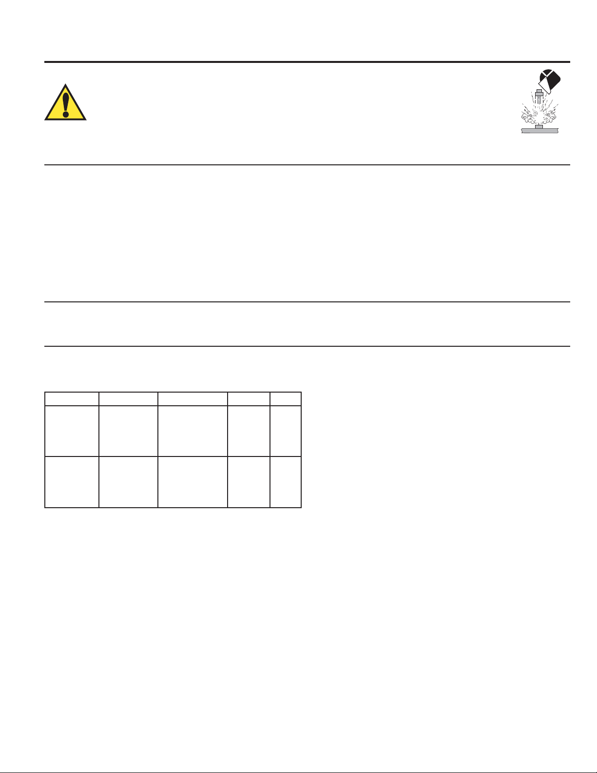
SAFETY INSTRUCTIONS
1. Depressurize and vent system prior to installation or removal.
2. Con rm chemical compatibility before use.
3. Do not exceed maximum temperature/pressure speci cations.
4. Wear safety goggles or faceshield during installation/service.
5. Do not alter product construction.
6. If this equipment is used in a manner not speci ed by the manufacturer, the protection provided
by the equipment may be impaired.
7. This device is not approved for use or installation in hazardous locations.
Description
The 2537 Paddlewheel Flowmeter Series offer low ow, low power and high resolution with various output options such as a Volumetric
Pulse, Pulse Divider, Flow Switch, Digital (S
interface.
• The 4 to 20 mA model provides a blind current loop output.
• The Digital (S
3
L) model provides a Digital (S3L) output for use with the Signet 8900 Multi-Parameter Controller or 9900 Transmitter.
• The Multi model uses a single relay (mechanical or solid state) and has three selectable operating modes:
• Divider Mode scales the paddlewheel frequency down to accommodate low frequency input devices.
• Total Mode outputs one pulse per a set volume of uid.
• Flow Switch Mode uses a single relay for Hi or Lo alarm operation.
A small LCD enables the 2537 to be programmed without any external equipment. During normal operation the display is not visible.
3
L), or 4 to 20 mA. This unit can be con gured on-site directly through the built-in user
For earlier versions of this sensor, please visit our manual archives at www.gfsignet.com and download the 2537 rev C manual.
Specifi cations
General
Wetted Materials
Model Suffi x Sensor Body Rotor Pin O-ring
-P0, -P1 glass- lled PP PVDF, Black;
optional ETFE
w/ or w/o carbon
ber reinforced
PTFE sleeve
-T0 PVDF, Natural PVDF, Natural;
optional ETFE
w/ or w/o carbon
ber reinforced
PTFE sleeve
Titanium FPM
PVDF,
Natural
FPM
Paddlewheel Sensor Performance Specifi cations
Pipe Size Range: DN15 to DN200 (½ in. to 8 in.)
Min. Reynolds Number: 4500
Paddlewheel Frequency: 49 Hz per m/s nominal
(15 Hz per ft/s nominal)
Operating Range: 0.1 m/s to 6 m/s (0.3 ft/s to 20 ft/s)
Linearity: ±1% of max. range @ 25 °C (77 °F)
Repeatability: ±0.5% of max. range @ 25 °C (77 °F)
Electronics Performance Specifi cations
Input Frequency Range: 1 to 1000 Hz
System Response: 100 ms update rate nominal
Environmental Requirements
Enclosure Rating: NEMA 4X/IP65
Storage Temperature: -10 to 75 °C (14 to 167 °F)
Case: PBT, yellow
Inside Cover: Valox, black
Wiring Ports: ½ in. NPT threads; liquid-tight
connector accepts cables 7 to
Ambient Temperature: 0 to 65 °C (32 to 150 °F)
Relative Humidity: 0 to 90% RH, non-condensing
Altitude: 2000 m (6,562 ft)
Pollution Degree: 2
10 mm OD (0.275 in. to 0.394 in.)
Output Specifi cations
Power Requirements
Multi:
Signal Averaging: Programmable 0 to 100 seconds
Sensitivity Response: Programmable 0 to 9 scale
with Dry-Contact Relay: 24 VDC nominal, ±10%, regulated
30 mA max. current
with Solid-State Relay: 5 to 24 VDC nominal, ±10%, regulated
30 mA max. current
Digital (S
3
L): 5.0 VDC min. to 6.5 VDC max.
Pulse Divider/Total Pulse Output
Pulse Divider Setting: 1.0000 to 99999
Maximum pulse rate: 300 Hz
Maximum pulse width: 50 ms
30 mA max. current (1.5 mA nominal)
4 to 20 mA: 400 mV max. ripple voltage
30 mA max. current
Reverse Polarity and Short Circuit Protected: Up to 40 V, 1 hour
Over-Voltage Protection: > 40 VDC over 1 hour
Page 2
Flow Switch Output
Relay Modes: Low, High
Time Delay: 0.0 to 6400.0 seconds
Hysteresis: Adjustable in Engineering Units
Relay Specifi cations
Dry Contact SPDT: 5 A @ 30 VDC, 5 A @ 250 VAC
Solid-State Relay: 100 mA @ 40 VDC, 70 mA @ 33 VAC
3
Digital (S
Type: Serial ASCII, TTL level 9600 bps
Maximum Cable Length: See Digital (S
L) output
3
L) speci cations
Current output (Passive 4 to 20 mA)
Loop Accuracy: ±32 A (@ 25 °C @ 24 VDC)
Loop Resolution: 5 A
Temp. Drift: ±1 A per °C max.
Power Supply Rejection: ±1 uA per V
Maximum Cable Length: 305 m (1,000 ft)
Max Loop Resistance: 600 @ 24 VDC, 1 K @ 32 VDC
Fluid Conditions
Pressure/Temperature Ratings:
Polypropylene Body:
• 12.5 bar (180 psi) max. @ 20 °C (68 °F)
• 1.7 bar (25 psi) max. @ 85 °C (185 °F)
PVDF Body:
• 14 bar (200 psi) max @ 20 °C (68 °F)
• 1.7 bar (25 psi) max @ 85 °C (185 °F)
Standards & Approvals
• UL
• CE
• Manufactured under ISO 9001 for Quality, ISO 14001
for Environmental Management and OHSAS 18001 for
occupational health and safety.
China RoHS (Go to www.gfsignet.com for details)
Declaration of Conformity according to FCC Part 15
This device complies with Part 15 of the FCC rules.
Operation is subject to the following two conditions:
(1) This device may not cause harmful interference, and,
(2) This device must accept any interference received, including
interference that may cause undesired operation.
ps
i
bar
14
200
11
160
8
120
6
80
PVDF
Polypropylene
3
40
Intended Use: This product is intended for use in industrial water treatment
and wastewater treatment applications where the chemical content and the uid
temperatures are consistent with the speci cations listed herein.
This device is not approved for use or installation in fl ammable liquids.
°F
0 40 80 120 160 200
°C
-18 4
27
49
71 93
240
115
Chemical Compatibility
Georg Fischer Signet products are manufactured in a variety of wetted materials to suit various liquids and chemicals.
All plastic materials including typical piping types (PVC, PVDF, PP and PE) are more or less permeable to contained media, such as
water or volatile substances, including some acids. This effect is not related to porosity, but purely a matter of gas diffusion through the
plastic.
If the plastic material is compatible with the medium according to the application guidelines, the permeation will not damage the plastic
itself. However, if the plastic encloses other sensitive components, as is the case with GF Signet plastic paddlewheel sensors, these
may be affected or damaged by the media diffusing through the plastic body and rotor.
PVDF paddlewheel sensors may experience failure when used in hot nitric acid applications. PVDF is known to allow for substantial
permeation of nitric acid constituents without being damaged itself. No clear guideline can be given here, since the damaging effect to
the sensor is highly dependent on temperature, pressure and concentration.
Utilizing sensors in applications with aggressive substances is possible. On special request GF Signet can provide sensors with a
different internal resin encapsulation (potting) that will delay the damaging effect of acids to the sensors.
WARNING
The retaining nuts of paddlewheel sensors are not designed for prolonged contact with aggressive substances. Strong acids,
caustic substances and solvents or their vapor may lead to failure of the retaining nut, ejection of the sensor and loss of the
process fl uid with possibly serious consequences, such as damage to equipment and serious personal injury. Retaining nuts
that may have been in contact with such substances, e.g. due to leakage or spilling, must be replaced.
For all Special Product inquiries or to place an order, please email
signet-specialproduct@georgfi scher.com.
2 Signet 2537 Flowmeter
Page 3
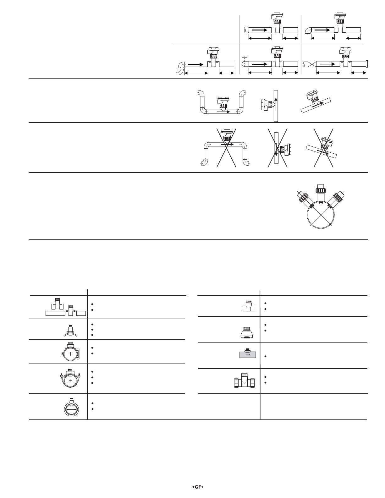
Location of Fitting
+45°
-45°
0°
Process
Pipe
Recommended sensor upstream/downstream mounting
requirements:
Reducer
15 x I.D. 5 x I.D.
90° Elbow
20 x I.D. 5 x I.D.
Select a location with suf cient length of straight pipe
immediately upstream of the sensor.
Locating the sensor in a trap or where the ow is upward
2 x 90° Elbow
25 x I.D. 5 x I.D.
2 x 90° Elbow
3 dimensions
40 x I.D. 5 x I.D.
OKOK OK
helps to protect the sensor from exposure to air bubbles
when the system is in operation.
These con gurations are not recommended because it is
dif cult to keep the pipe full.
+GF+
+GF+
+
GF
+
Sensor Mounting Position
• Horizontal pipe runs: Mount sensor in the upright (0°) position for best performance. Mount at a
maximum of 45° when air bubbles are present (pipe must be full). Do not mount on the bottom of the
pipe when sediments are present.
• Vertical pipe runs: Mount sensor in any orientation; however, downward ow is not recommended.
Upward ow is preferred to ensure full pipe.
Pump/Valve
50 x I.D. 5 x I.D.
+
GF
+
Vertical flow is OK if the pipe remains full at all times.
+
GF
+
Installation: Pipe fi ttings
Georg Fischer Signet offers a wide selection of installation ttings that control the position of the paddlewheel in relation to the
dimensions of the pipe.
Type Description
Plastic
tees
PVC
Glue-on
Saddles
PVC
Saddles
Iron
Strap-on
saddles
Metric
Wafer Fitting
d
0.5 to 2 inch versions (MPVC or CPVC)
2.5 to 4 inch versions (PVC)
Available in 10 and 12 inch sizes only
Cut 2-1/2 inch hole in pipe
Weld in place using solvent cement
2 to 4 inch, cut 1-7/16 inch hole in pipe
6 to 8 inch, cut 2-1/8 inch hole in pipe
2 to 4 inch, cut 1-7/16 inch hole in pipe
Over 4 inch, cut 2-1/8 inch hole in pipe
Special order 14 in. to 36 in.
For pipes DN65 to 200 mm
PP or PVDF
Type Description
Iron, Carbon Steel,
316 SS Threaded
tees
Carbon steel &
stainless steel
Weld-on
0.5 to 2 in. versions
Mounts on threaded pipe ends
2 to 4 inch, cut 1-7/16 inch hole in pipe
Over 4 inch, cut 2-1/8 inch hole in pipe
Weldolets
Fiberglass
tees
Metric
Union
Fitting
FPT
1.5 in. to 2 in. PVDF insert
For pipes from DN 15 to 50 mm
PP or PVDF
3Signet 2537 Flowmeter
Page 4
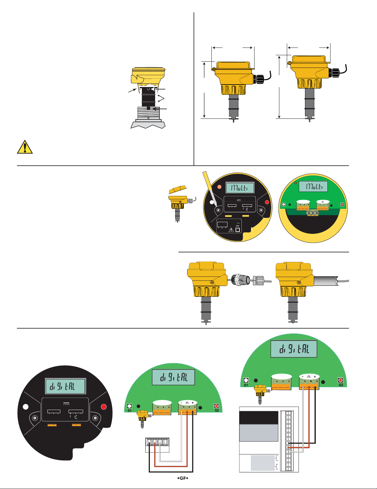
Installation
sensor
cap
tab
notch
Lubricate
O-rings
-
+
-
+
-
+
-
+
-
+
-
+
T
P
t
T
P
t
T
P
t
T
P
t
-
+
Plastic sensor installation tips
• Inspect the sensor O-rings for nicks and other damage that
may compromise the seal.
• Lubricate O-rings with a non-petroleum based, viscous
lubricant (grease) compatible with the system.
• Using an alternating/twisting motion,
lower the sensor into the tting, making
sure the conduit ports on the yellow
housing are pointing in the direction
of ow.
• Engage one thread of the sensor cap
then turn the sensor until the alignment
tab is seated in the tting notch.
Dimensions
130 mm
(5.12 in.)
97 mm
(3.82 in.)
171 mm
(6.73 in.)
97 mm
(3.82 in.)
HAND-TIGHTEN THE THREADED NUT ONTO THE INSTALLATION FITTING. DO NOT USE TOOLS! DO NOT
USE THREAD SEALANT OR LUBRICANTS ON THE
FITTING THREADS OR THE SENSOR CAP.
Wiring
Electrical connections to this product should be made only by
quali ed personnel.
To access the wiring terminals:
• Turn yellow cap ¼ turn counterclockwise to remove.
• Remove the two retaining screws and remove the black
cover.
• Route all cables through the conduit ports before connecting
them to the terminals.
• Wiring terminals are rated for 16 to 22 AWG conductors.
• The cable must be 7 to 10 mm in diameter (0.275 to
0.394 in.) to seal properly in the liquid tight connector.
• The conduit ports have ½ inch NPT threads. After routing the
cables, seal the port with a liquid tight conduit connector
(3-9000.392-1) or with conduit.
• For conduit installations:
• Thread conduit with ½ in. NPT threads directly into the
conduit port.
• For conduit with ISO threads, use the black thread adapter
included with the connector kit.
• To comply with NEC requirements, do not use any metal
conduit in the installation.
2537 Paddlewheel Flowmeter
for ½ in. to 4 in. pipe
Power Rating:
24VDC 0.03 AMP
WIRING DIAGRAM
Sensor
PW/OUT
+
RED
SHLD
Dry-Contact
N/O
Relay
Relay Rating:
5A @ 250VAC
5A @ 30VDC
N/C
COM
BLK
Using the liquid-tight
connector
2537 Paddlewheel Flowmeter
for 5 to 8 in. pipe
Blk Red Shld
3-2505.611A
S1
S2
Using conduit
Wiring: Digital (S3L) Output
The Digital (S3L) output is compatible with the 3-8900 Multi-Parameter Controller
and the 3-9900 Transmitter.
Blk Red Shld
T
Power Rating:
5 - 6.5VDC 0.03 AMP
WIRING DIAGRAM
Sensor
Blk Red Shld
BLK
RED
S1
SHLD
PW/OUT
-
+
+
3-2505.613A
S2
S1
Blk Red Shld
DATA
V+
GND
SHLD
-
+
S2
Connection to
9900 Transmitter
S1
I/O Module 3-8900.401-X
+5VDC (Black)
Frequency
Input
Freq. Input (Red)
1
GND (Shield)
+5VDC (Black)
Frequency
Input 2
Freq. Input 2 (Red)
OR
S3L
Input
2
S3L
Input
1
3
S L (Red)
GND (White/Shield)
+5VDC (Black)
3
S L (Red)
GND (White/Shield)
Analog Output 1
(if applicable)
Analog Output 2
(if applicable)
1
2
3
4
5
6
7
8
9
10
11
+
12
-
13
+
14
-
4 Signet 2537 Flowmeter
-
3-8900.621C
Connection to
8900 Controller
+
S2
Page 5
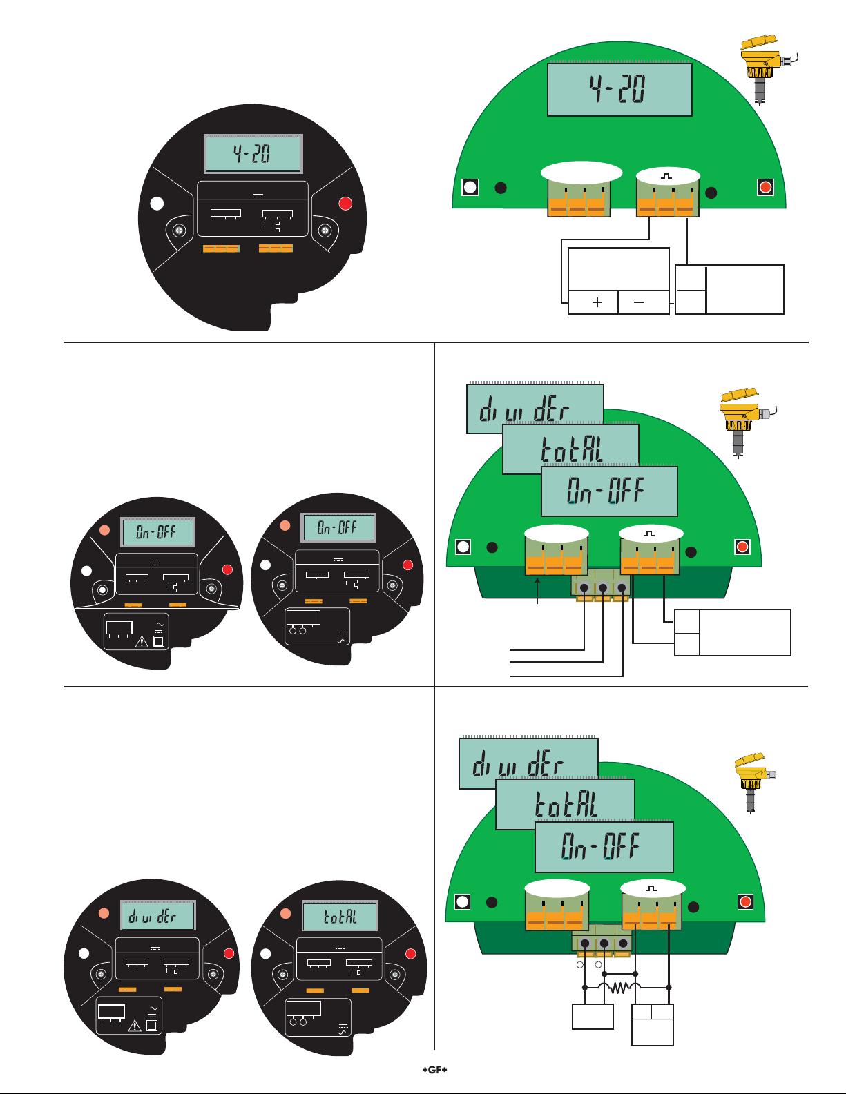
Wiring: 4 to 20 mA Output
-
+
-
+
-
+
-
+
-
+
-
+
T
P
t
T
P
t
-
+
-
+
T
P
t
T
P
t
-
+
-
+
-
+
-
+
T
P
t
T
P
t
The 4 to 20 mA output can be connected to Chart Recorders, PLCs or
any device that requires a 4 to 20 mA signal.
The 4 to 20 mA model requires an external power source of
12 to 32 VDC.
T
P
Power Rating:
12 - 32VDC 0.03 AMP
WIRING DIAGRAM
Sensor
Blk Red Shld
BLK
RED
SHLD
S1
PW/OUT
-
t
+
3-2505.614A
S2
S1
Blk Red Shld
Internal sensor
connections
Programmable Logic Controller
Datalogger
Chart Recorder
4 to 20 mA Loop monitor
S2
+
Power Supply
12 to 32 VDC, 0.03 A
-
Wiring: Flow Switch Output (On-OFF)
• The Flow Switch mode allows a single relay that is
programmable as a HIGH setpoint or LOW setpoint.
• The relay may be a dry-contact type or a solid state type.
• The dry contact relay requires an external power source of
24 VDC ± 10%.
• The solid state relay requires an external power source of
5 to 24 VDC.
T
T
P
Power Rating:
24VDC 0.03 AMP
WIRING DIAGRAM
Sensor
BLK
Blk Red Shld
Dry-Contact
N/O
Relay
RED
Relay Rating:
5A @ 250VAC
5A @ 30VDC
N/C
COM
S1
SHLD
PW/OUT
-
t
+
3-2505.611A
+
S2
S1
P
Power Rating:
5 - 24VDC 0.03 AMP
WIRING DIAGRAM
Sensor
Blk Red Shld
BLK
RED
SHLD
Solid-State
Relay
Relay Rating:
1 2
100mA @ 40VDC
Load
70mA @ 33VAC
3-2505.616A
PW/OUT
-
t
+
3-2505.612A
+
Wiring: Pulse Output
• The "Multi" mode allows a single relay that is programmable
as a Flow Switch, Volumetric pulse output or as a simple pulse
divider output.
• The relay may be a dry-contact type or a solid state type.
• The Dry Contact Relay requires an external power source of
24 VDC ± 10%.
• The Solid State Relay requires an external power source of
5 to 24 VDC.
• Solid State Relay requires a pull-up resistor (10K ohm
recommended). Consult your instrument/PLC manual for
wiring information.
Dry Contact Relay Wiring
• The wiring is identical for On-OFF and Pulse modes.
Blk Red Shld
S1
S2
Internal sensor
connections
Normally Open
Common
Normally Closed
S2
+
Power Supply
24 VDC, 0.03 A
-
Solid State Relay Wiring
• The wiring is identical for On-OFF and Pulse modes
Blk Red Shld
.
S1
Power Rating:
24VDC 0.03 AMP
WIRING DIAGRAM
Sensor
PW/OUT
+
Blk Red Shld
BLK
RED
Relay Rating:
Relay
N/C
COM
5A @ 250VAC
5A @ 30VDC
SHLD
S1
Dry-Contact
N/O
3-2505.611A
-
+
S2
S1
Power Rating:
5 - 24VDC 0.03 AMP
WIRING DIAGRAM
Sensor
BLK
RED
Blk Red Shld
SHLD
3-2505.616A
Solid-State
Relay
Relay Rating:
1 2
100mA @ 40VDC
Load
70mA @ 33VAC
PW/OUT
-
Load
+
3-2505.612A
+
S2
1 2
I/O
10KΩ
Power Supply
5 to 24 VDC,
0.03 A
+–
S2
5Signet 2537 Flowmeter
Page 6

Operation
T
P
t
T
P
t
T
P
t
T
P
t
The 2537 Flowmeter is available in three different
models. The programming menus vary signi cantly
from one model to another.
This chart is provided inside the yellow cover to assist
in navigating the menus in the 2537.
Mode Action
View Display Flow Rate Go to MENU Go to VIEW
Menu 1X Next Menu 1X Display Current Value Previous Mode
Go to Edit Previous Mode
1X Shift digit to right Previous Mode
Edit 1X Increment Value Go to SAVE Previous Mode
SAVE 1X Toggle 1X Store Change N/A
Menus
3-2537-1C-XX, 3-2537-2C-XX 3-2537-5C-XX 3-2537-6C-XX
T
P
t
View Mode Function
• All models display the model name: Multi, Digital or 4-20.
• If the white key (S1) is held down for three seconds, the ow rate is displayed for 10 minutes before
reverting back to the model name.
• In the Multi Model, if the “Multi” menu item is set to “divider”, then the divided pulse output will be
displayed in pulses/seconds (p/s).
6 Signet 2537 Flowmeter
Page 7

Menu Details
This table shows the de nition of each menu function, the setting parameters and the page where detailed instructions can be located.
Menu Function Defi nition Setting Parameters
Flow Unit Liters or Gallons per sec, min., hour or day See list on page 8 page 8
K-Factor Set PULSES per VOLUME UNIT 0.0001 to 999999 page 8
Average Smooths out erratic ow conditions 0 to 100 seconds page 9
Sensitivity Overrides Average for large rate changes 0 to 9 page 9
Mode Select the output mode Total or Divider or On-OFF page 10
P-Factor As PULSE DIVIDER, divides input freq. 1.0000 to 99999 page 10
P-Factor As PULSE TOTAL, multiplies K-Factor 1.0000 to 99999 page 10
Relay Logic Select Hi alarm or Lo alarm mode Hi or Lo page 11
Relay Set Set Relay Setpoint 0.0000 to 99999 page 11
Relay Hysteresis Rate inside Setpoint to DEENERGIZE relay 0.0000 to 99999 page 11
Relay Delay Time delay before relay is ENERGIZED 0000.0 to 6400.0 page 11
4 Set Set ow RATE to be represented by 4 mA 0.0000 to 99999 page 8
20 Set Set ow RATE to be represented by 20 mA 0.0000 to 99999 page 8
Contrast Adjust visibility of liquid crystal display 1 to 3 page 8
More
Information
7Signet 2537 Flowmeter
Page 8

t
t
T
P
t
T
P
t
T
P
t
T
P
t
t
T
P
t
t
T
P
Flow Units
T
P
t
T
P
t
T
P
t
T
P
t
T
P
t
T
P
t
T
P
t
T
P
t
This function is available on these
versions of the 2537.
Select the volumetric units for the ow measurement.
Liters/second
Liters/minute
(Factory setting)
Gallons/second
Gallons/minute
T
P
T
P
t
t
K-Factor
A K-Factor is the number of pulses
a sensor will generate for each
engineering unit of uid that passes
T
P
T
P
t
t
the sensor. The factory setting is
60.0000. Locate the K-Factor in the
tables on page 12 and 13.
This function is
available on the above
versions of the 2537.
Minimum value
Maximum value
Liters/hour
Liters/day
Gallons/hour
Gallons/day
Example: Set the Flow Units to Gallons per minute:
Save the new setting:
.
.
2s
2s
.
2s
Go to next
menu item
Return to
Normal Operation
Set 4 and Set 20
This function is available on
these versions of the 2537.
These two functions are used to span the 4 to 20 mA output
signal to the required range.
The factory setting is 4 to 20 mA = 0 to 10.000
Only the 20 mA span is illustrated here.
Example: Set 20 mA = 500 GPM.
2s
x5
2s
Save the new setting:
2s
Example: Set the K-Factor to 63.5 Pulses per Gallon:
1.
2s
2.
3.
2s
4.
5.
x2
x3
Save the new setting:
2s
6.
Return to
T
P
T
P
Normal Operation
7.
x5
Set Contrast
This function is available on
these versions of the 2537.
Go to next
menu item
All models of the 2537 have the CONTRAST adjustment. It is
always located at the end of the menu.
1.
2.
Repeat until
To access the adjustment, enter the
2s
menu and scroll until the Contrast
display appears.
x1
Three levels of adjustment are
available. The factory setting of
3 is the highest contrast setting.
Choose:
OR OR
Save the new setting:
2s
t
t
x4
x2
8 Signet 2537 Flowmeter
Return to
Go to next
menu item
Normal Operation
Go to next
menu item
Return to
Normal Operation
Page 9

t
T
P
t
T
P
t
T
P
t
T
P
t
t
T
P
t
T
P
t
10 s2 s 20 s 30 s 40 s 50 s 60 s 70 s
No AVERAGING, no SENSITIVITY
AVERAGING only
AVERAGING and SENSITIVITY
Averaging and Sensitivity Settings
P
T
t
T
P
t
T
P
t
• Because ideal ow conditions are often impossible to achieve, the ow rate is often erratic, which causes erratic readings in control
features (e.g., relays, 4 to 20 mA loops, etc.) that are associated with the ow rate.
• The best solution to these problems is to correct any piping de ciency that causes the instability. This may involve longer straight
runs upstream, reducing the pipe size to maintain a full pipe at all times, and other installation changes. In many situations, however,
these measures are simply not possible.
• The 2537 meter provides two tools that are designed to "work around" these de ciencies. The Averaging and the Sensitivity features
should be studied before making adjustments.
Averaging Time in Seconds (Factory set: 0 seconds)
• Set the time the meter will use as the averaging period. The range is from 0 (no average applied to input) to 100 (seconds of
averaging applied to input).
Use higher averaging times to smooth the display and current output where the ow in the pipe is erratic.
Quick Response Sensitivity (Factory set: 0)
• Set the relative degree of change in the ow rate required to allow the 2537 to disable the AVERAGING and jump to a new ow rate
immediately. The scale is from 0 (least sensitive, averaging is never disabled.) to 9 (a very small change in ow rate will disable the
averaging).
With AVERAGING set to 0 (zero) and with SENSITIVITY set to zero,
the 2537 responds to every unstable shift in the ow. The dashed
red line represents the actual output of the ow sensor in unstable
ow conditions.
With AVERAGING set to 50 seconds and SENSITIVITY still set to
zero the ow rate is stabilized, but a sharp change in ow rate is not
represented for 50 seconds or longer (dotted green line).
With AVERAGING at 50 seconds and SENSITIVITY set to 4 OR 5,
the ow rate is stabilized, while the sudden shift in ow is re ected
very quickly (solid blue line).
NOTE: The SENSITIVITY function is ineffective if the AVERAGING function is set to zero (seconds).
Set Averaging
This function is available on
these versions of the 2537:
The factory setting is 0 (zero). The factory setting is 0 (zero).
Minimum value
T
P
T
P
t
t
Set Sensitivity
This function is available on
these versions of the 2537:
Maximum value
Example:
Set the Averaging for 50 seconds.
1.
2.
3.
x2
4.
2s
2s
Save the new setting:
2s
Return to
Go to next
menu item
Normal Operation
Example: Set the Sensitivity to 5.
1.
2s
2.
3.
4.
x3
2s
x5
T
P
Minimum value
Maximum value
Save the new setting:
2s
Go to next
menu item
T
P
T
t
P
t
t
Return to
Normal Operation
5.
x5
9Signet 2537 Flowmeter
Page 10

Mode
t
t
T
P
T
P
t
t
T
P
t
t
P
T
T
P
t
T
P
t
This function is available on
these versions of the 2537:
Select DIVIDER or TOTAL operation.
The factory setting is TOTAL.
P-Factor
This function is available on
these versions of the 2537:
The factory setting is 1.0000
T
P
t
PULSE DIVIDER Output = Input pulses ÷ P-Factor
DIVIDER allows you to set a scaling value (P-Factor) from
1.0000 to 99999.
Example: If the P-Factor is set for 2, then the 2537 will output
one pulse for every 2 pulses received from the sensor.
This selection enables the output frequency to be scaled down
to match associated equipment capabilities.
When using the PULSE DIVIDER output, associated equipment
must divide the K-Factors in this manual by the P-Factor for
correct calibration.
123579468
1110 12
Pulses IN
123 4
56
Pulses OUT
PULSE TOTAL Output = Input pulses ÷ (K-Factor × P-Factor)
TOTAL is a traditional pump pulser function. This selection will
allow the entry of a K-Factor to de ne a volumetric unit, then set
a P-Factor to de ne the number of volumetric units required to
generate one pulse out.
Example:
Set the Total Pulse output so there is one pulse out for each
2 gallons that passes the sensor if the K-Factor is 3.0.
Minimum value
Maximum value
In PULSE DIVIDER mode the P-Factor divides:
The pulse stream from the paddlewheel sensor will be divided
by the P-Factor. The resulting frequency is output through a
relay.
In PULSE TOTAL mode the P-Factor multiplies:
The pulse stream from the paddlewheel sensor is divided
by the K-Factor MULTIPLIED by the P-factor. The resulting
frequency is output through a relay.
1.
2s
2.
3.
4.
5.
2s
x4
x2
1. K-Factor = 3.0 (pulses in per gallon)
Save the new setting:
2. P-Factor = 2 (gallons out per pulse)
1 Gal 4 Gal
2 Gal 3 Gal
2s
2135468791110 12
Pulses IN
1
2
Pulses OUT
.
2s
.
2s
.
2s
10 Signet 2537 Flowmeter
Go to next
Save the new setting:
2s
Go to next
menu item
Return to
Normal Operation
menu item
Return to
Normal Operation
Page 11

t
T
P
t
T
P
t
Set Relay Operation
T
P
t
T
P
t
t
t
T
P
t
T
P
t
P
T
t
t
T
P
t
T
P
t
t
T
P
The On-OFF mode has one relay (SPDT or solid-state) that can be programmed as a HIGH (Hi)
alarm or a LOW (Lo) alarm.
1. Select HI or LO Relay Alarm logic
A HI alarm will be activated when the
ow rate rises ABOVE the setpoint.
A LO alarm will be activated when the
ow rate falls BELOW the setpoint.
The factory setting is Hi(gh).
2. Program the SETPOINT.
The SETPOINT is the ow rate
where the relay will be energized.
The factory setting is 5.0000.
Minimum value
Maximum value
Example: Change the Relay Logic to Low:
1.
2.
3.
4.
2s
x4
2s
Example: Change the Setpoint to 8.0000:
1.
2.
3.
4.
5.
2s
x5
2s
x3
Save the new setting:
2s
Return to
Go to next
menu item
Normal Operation
Save the new setting:
2s
Return to
Go to next
menu item
Normal Operation
3. Program the HYSTERESIS.
Hysteresis holds a relay energized until the
Example: Change the Hysteresis to 5.0000:
1.
2s
Save the new setting:
2s
ow rate moves this amount past the setpoint.
The factory setting is 0.5000
Minimum value
Maximum value
4. Program the DELAY.
When the ow rate reaches the setpoint, the
2537 will wait this long (in seconds) before
triggering the alarm.
The factory setting is 0000.0 seconds.
Minimum value
Maximum value
2.
3.
4.
x6
2s
x5
Example: Change the Delay to 10.0:
1.
2.
3.
4.
5.
2s
x7
2s
Return to
Go to next
menu item
Normal Operation
Save the new setting:
2s
Return to
Go to next
menu item
Normal Operation
11Signet 2537 Flowmeter
Page 12

K-Factors
When using the PULSE DIVIDER mode, associated equipment must divide the K-Factors by the P-Factor.
A K-Factor is the number of pulses a sensor will generate for each engineering unit of uid that passes the sensor. K-Factors for water
are listed below in U.S. gallons and liters. For example, in a 1 inch SCH 80 PVC pipe, using the MPV8T010 PVC tting, the 2537
paddlewheel generates 335.53 pulses per gallon of water passing the rotor.
Molded Tees Saddles Metal Tees
PIPE
SIZE
(IN.)
SCH 80 MOLDED TEES FOR SCH 80 PVC PIPE
1/2
3/4
1
1-1/4
1-1/2
2
2-1/2 PV8T025 42.994 11.359
3 PV8T030 26.652 7.0414
4 PV8T040 15.006 3.9645
FITTING
MPV8T005F
MPV8T005
MCPV8T005F
MPV8T007F
MPV8T007
MCPV8T007F
MPV8T010F
MPV8T010
MCPV8T010F
MPV8T012F
MPV8T012
MCPV8T012F
MPV8T015F
MPV8T015
MCPV8T015F
MPV8T020F
MPV8T020
MCPV8T020F
2537 SENSOR
U.S.
GAL
1027.1 271.37
583.19 154.08
335.53 88.65
178.79 47.24
121.42 32.08
71.44 18.87
LITERS
PIPE
SIZE
(IN.)
SCH 80 PVC SADDLES FOR SCH 80 PVC PIPE
2 PV8S020 66.739 17.633
2-1/2 PV8S025 42.994 11.359
3 PV8S030 26.652 7.0414
4 PV8S040 15.006 3.9645
6 PV8S060 8.3246 2.1994
8 PV8S080 5.0164 1.3253
SCH 80 PVC SADDLE ON SCH 40 PVC PIPE
2 PV8S020 54.700 14.452
2-1/2 PV8S025 37.159 9.8175
3 PV8S030 23.697 6.2608
4 PV8S040 13.456 3.5552
6 PV8S060 7.4594 1.9708
8 PV8S080 4.5292 1.1966
FITTING
2537 SENSOR
U.S.
GAL
LITERS
PIPE
SIZE
(IN.)
CARBON STEEL TEES ON SCH 40 PIPE
1/2 CS4T005 756.00 199.74
3/4 CS4T007 438.69 115.90
1 CS4T010 286.78 75.768
1-1/4 CS4T012 121.22 32.026
1-1/2 CS4T015 91.139 24.079
2 CS4T020 54.468 14.391
STAINLESS STEEL TEES ON SCH 40 PIPE
1/2 CR4T005 734.20 193.98
3/4 CR4T007 412.10 108.88
1 CR4T010 252.70 66.764
1-1/4 CR4T012 128.12 33.849
1-1/2 CR4T015 77.320 20.428
2 CR4T020 45.780 12.095
GALVANIZED IRON TEES ON SCH 40 PIPE
1 IR4T010 213.01 56.277
1-1/4 IR4T012 127.75 33.751
1 1/2 IR4T015 94.401 24.941
2 IR4T020 59.420 15.699
BRONZE TEES ON SCH 40 PIPE
1 BR4T010 213.01 56.277
1-1/4 BR4T012 127.75 33.751
1-1/2 BR4T015 94.401 24.941
2 BR4T020 59.420 15.699
COPPER TEE FITTINGS ON COPPER PIPE
SCH K
1/2 CUKT005 917.84 242.50
3/4 CUKT007 428.27 113.15
1 CUKT010 256.43 67.749
1-1/4 CUKT012 176.44 46.615
1-1/2 CUKT015 115.69 30.565
2 CUKT020 63.385 16.746
COPPER TEE FITTINGS ON COPPER PIPE
SCH L
1/2 CUKT005 858.22 226.74
3/4 CUKT007 385.74 101.91
1 CUKT010 241.64 63.841
1-1/4 CUKT012 170.90 45.152
1-1/2 CUKT015 112.03 29.598
2 CUKT020 61.74 16.310
FITTING
2537 SENSOR
U.S.
GAL
LITERS
12 Signet 2537 Flowmeter
Page 13

K-Factors
Union Tees
PIPE
SIZE
POLYPROPYLENE TEES (DIN/ISO AND BS AND ANSI)
DN15 PPMT005 952.87 251.75
DN20 PPMT007 563.10 148.77
DN25 PPMT010 291.60 77.042
DN32 PPMT012 169.22 44.709
DN40 PPMT015 103.90 27.450
DN50 PPMT020 60.789 16.060
DN65 PPMT025 41.498 10.964
DN80 PPMT030 26.786 7.0769
DN100 PPMT040 17.415 4.6011
DN125 PPMT050 10.168 2.6864
DN150 PPMT060 7.3119 1.9318
DN200 PPMT080 3.9946 1.0554
FITTING
2537 SENSOR
U.S. GAL LITERS
Union Tees
PIPE
SIZE
PVDF FITTINGS (DIN/ISO AND BS AND ANSI)
DN15 SFMT005 827.26 218.56
DN20 SFMT007 489.87 129.42
DN25 SFMT010 283.55 74.915
DN32 SFMT012 158.59 41.899
DN40 SFMT015 86.980 22.980
DN50 SFMT020 50.385 13.312
PVC FITTINGS (DIN/ISO) - EUROPE ONLY
DN15 PVMT005 972.37 256.90
DN20 PVMT007 485.69 128.32
DN25 PVMT010 297.27 78.540
DN32 PVMT012 170.25 44.980
DN40 PVMT015 103.71 27.400
DN50 PVMT020 59.500 15.720
DN65 PVMT025 34.973 9.2400
DN80 PVMT030 24.981 6.6000
DN100 PVMT040 16.275 4.3000
DN150 PVMT060 8.1756 2.1600
DN200 PVMT080 4.0878 1.0800
FITTING
2537 SENSOR
U.S. GAL LITERS
Wafer Fittings
PIPE
SIZE
POLYPROPYLENE WAFER FITTINGS (DIN/ISO)
DN65
DN80
DN100
DN125
DN150
DN200
PVDF WAFER FITTINGS (DIN/ISO)
DN65 SFMTF025 36.133 9.5465
DN80 SFMTF030 24.715 6.5297
DN100 SFMTF040 16.120 4.2589
DN125 SFMTF050 8.8624 2.3415
DN150 SFMTF060 6.4543 1.7052
DN200 SFMTF080 4.0720 1.0758
FITTING
PPMTE025
PPMTF025
PPMTE030
PPMTF030
PPMTE040
PPMTF040
PPMTE050
PPMTF050
PPMTE060
PPMTF060
PPMTE080
PPMTF080
2537 SENSOR
U.S. GAL LITERS
41.498 10.964
26.786 7.0769
17.415 4.6011
10.168 2.6864
7.3119 1.9318
3.9946 1.0554
Weldolets and Brazolets
PIPE
SIZE
(IN.)
STAINLESS STEEL WELDOLETS ON SCH 40 PIPE
2-1/2 CR4W025 37.600 9.9339
3 CR4W030 24.340 6.4306
4 CR4W040 13.920 3.6777
5 CR4W050 10.860 2.8692
6 CR4W060 7.5200 1.9868
8 CR4W080 4.3400 1.1466
CARBON STEEL WELDOLETS ON SCH 40 PIPE
2-1/2 CS4W025 37.600 9.9339
3 CS4W030 24.340 6.4306
4 CS4W040 13.920 3.6777
5 CS4W050 10.860 2.8692
6 CS4W060 7.5200 1.9868
8 CS4W080 4.3400 1.1466
COPPER/BRONZE BRAZOLETS ON SCH 40 PIPE
2-1/2 BR4B025 37.600 9.934
3 BR4B030 24.340 6.431
4 BR4B040 13.920 3.678
5 BR4B050 10.860 2.869
6 BR4B060 7.5200 1.987
8 BR4B080 4.3400 1.147
FITTING
2537 SENSOR
U.S. GAL LITERS
Iron Saddles
PIPE
SIZE
(IN.)
SCH 80 IRON SADDLES ON SCH 80 PIPE
2 IR8S020 64.720 17.099
2-1/2 IR8S025 42.480 11.223
3 IR8S030 26.420 6.980
4 IR8S040 14.700 3.884
5 IR8S050 12.180 3.218
6 IR8S060 8.4400 2.230
8 IR8S080 4.9000 1.295
SCH 80 IRON SADDLE ON SCH 40 PIPE
2 IR8S020 53.640 14.172
2-1/2 IR8S025 37.600 9.934
3 IR8S030 23.220 6.135
4 IR8S040 13.260 3.503
5 IR8S050 11.040 2.917
6 IR8S060 7.2400 1.913
8 IR8S080 4.4000 1.162
FITTING
2537 SENSOR
U.S. GAL LITERS
13Signet 2537 Flowmeter
Page 14

H-Dimensions
The plastic insert in Weldolet ttings MUST be removed during the welding process. When reinstalled, it is important that the insert be
threaded to the proper height ("H" dimension).
Weldolet “H” dimension
Part number inches mm
CS4W020 2.38 60.45
CS4W025 2.33 59.18
CS4W030 2.32 58.92
CS4W040 2.30 58.42
CS4W050 3.09 78.48
CS4W060 2.96 75.18
CS4W080 2.73 69.34
"H"
Weldolet “H” dimension
Part number inches mm
CR4W020 2.38 60.45
CR4W025 2.33 59.18
CR4W030 2.32 58.92
CR4W040 2.30 58.42
CR4W050 3.09 78.48
CR4W060 2.96 75.18
CR4W080 2.73 69.34
Maintenance and Cleaning
The 2537 requires very little maintenance.
• If the paddlewheel becomes fouled, it can be cleaned with mild detergents and a small brush.
• The electronics portion of the 2537 does not require maintenance or cleaning.
Rotor Replacement Procedure
1. To remove the rotor, insert a small screwdriver between the rotor and the ear of the sensor.
2. Twist the screwdriver blade to ex the ear outward enough to remove one end of the rotor and pin.
DO NOT ex the ear any more than necessary! If it breaks, the sensor cannot be repaired.
3. Install the new rotor by inserting one tip of the pin into the hole, then carefully ex the opposite ear
back enough to slip rotor into place.
14 Signet 2537 Flowmeter
Page 15

Notes
15Signet 2537 Flowmeter
Page 16

Ordering Information
Mfr. Part No. Code Description
2537 system for 0.5 in. to 4 in. pipes, with polypropylene body, Black PVDF rotor, Titanium pin, FPM O-rings
3-2537-1C-P0 159 001 291 Pulse/Flow Switch, DCR, -P0, Integral Mount
3-2537-2C-P0 159 001 292 Pulse/Flow Switch, SSR, -P0, Integral Mount
3-2537-5C-P0 159 001 295 Digital (S
3
L), Integral Mount
3-2537-6C-P0 159 001 296 4 to 20 mA, Integral Mount
2537 system for 5 in. to 8 in. pipes, with polypropylene body, Black PVDF rotor, Titanium pin, FPM O-rings
3-2537-1C-P1 159 001 303 Pulse/Flow Switch, DCR, -P1, Integral Mount
3-2537-2C-P1 159 001 304 Pulse/Flow Switch, SSR, -P1, Integral Mount
3-2537-5C-P1 159 001 307 Digital (S3L), Integral Mount
3-2537-6C-P1 159 001 308 4 to 20 mA, Integral Mount
2537 system for 0.5 in. to 4 in. pipes, with natural PVDF body, rotor and pin, FPM O-rings
3-2537-1C-T0 159 001 315 Pulse/Flow Switch, DCR, -T0, Integral Mount
3-2537-2C-T0 159 001 316 Pulse/Flow Switch, SSR, -T0, Integral Mount
3-2537-5C-T0 159 001 319 Digital (S
3
L), Integral Mount
3-2537-6C-T0 159 001 320 4 to 20 mA, Integral Mount
Accessories
Mfr. Part No. Code Description
3-2536.320-1 198 820 052 Rotor, PVDF Black
3-2536.320-2 159 000 272 Rotor, PVDF Natural
3-2536.320-3 159 000 273 Rotor, ETFE
3-2536.321 198 820 054 Rotor and Pin, PVDF Natural
3-2536.322-1 198 820 056 Sleeved Rotor, PVDF Black
3-2536.322-2 198 820 057 Sleeved Rotor, PVDF Natural
3-2536.322-3 198 820 058 Sleeved Rotor, ETFE
M1546-1 198 801 182 Rotor Pin, Titanium
M1546-2 198 801 183 Rotor Pin, Hastelloy-C
M1546-3 198 820 014 Rotor Pin, Tantalum
M1546-4 198 820 015 Rotor Pin, Stainless Steel
P51545 198 820 016 Rotor Pin, Ceramic
1220-0021 198 801 186 O-Ring, FPM
1224-0021 198 820 006 O-Ring, EPDM
1228-0021 198 820 007 O-Ring, FFPM
P31536 198 840 201 Sensor Plug, Polypro
3-8050.390-1 159 001 702 Retaining Nut Replacement Kit, NPT, Valox
3-8050.390-3 159 310 116 Retaining Nut Replacement Kit, NPT, PP
3-8050.390-4 159 310 117 Retaining Nut Replacement Kit, NPT, PVDF
3-8050.391 159 001 703 Retaining Nut Replacement Kit, NPT, Stainless Steel
3-9000.392-1 159 000 839 Liquid tight connector kit, NPT (1 piece)
3-9000.392-2 159 000 841 Liquid tight connector kit, PG 13.5 (1 piece)
3-9000.392-3 159 001 430 Liquid-tight connector kit, dual-cable gland
7300-7524 159 000 687 24 VDC Power Supply 7.5 W, 300 mA
7300-1524 159 000 688 24 VDC Power Supply 15 W, 600 mA
7300-3024 159 000 689 24 VDC Power Supply 30 W, 1.3 A
7300-5024 159 000 690 24 VDC Power Supply 50 W, 2.1 A
7300-1024 159 000 691 24 VDC Power Supply 100 W, 4.2 A
®
Georg Fischer Signet LLC, 3401 Aerojet Avenue, El Monte, CA 91731-2882 U.S.A. • Tel. (626) 571-2770 • Fax (626) 573-2057
For Worldwide Sales and Service, visit our website: www.gfsignet.com • Or call (in the U.S.): (800) 854-4090
For the most up-to-date information, please refer to our website at www.gfsignet.com
3-2537.090 Rev G 9/12 English © Georg Fischer Signet LLC 2012
 Loading...