

Page 1
Signet 2250 Hydrostatic Level Sensor
English
*3-2250.090*
3-2250.090 Rev. E 06/13 English
Safety Instructions
1. Prior to installation or removal:
• Depressurize and vent system
• Drain below sensor level
2. Confi rm chemical compatibility before use.
3. Do not exceed maximum temperature/pressure specifi cations.
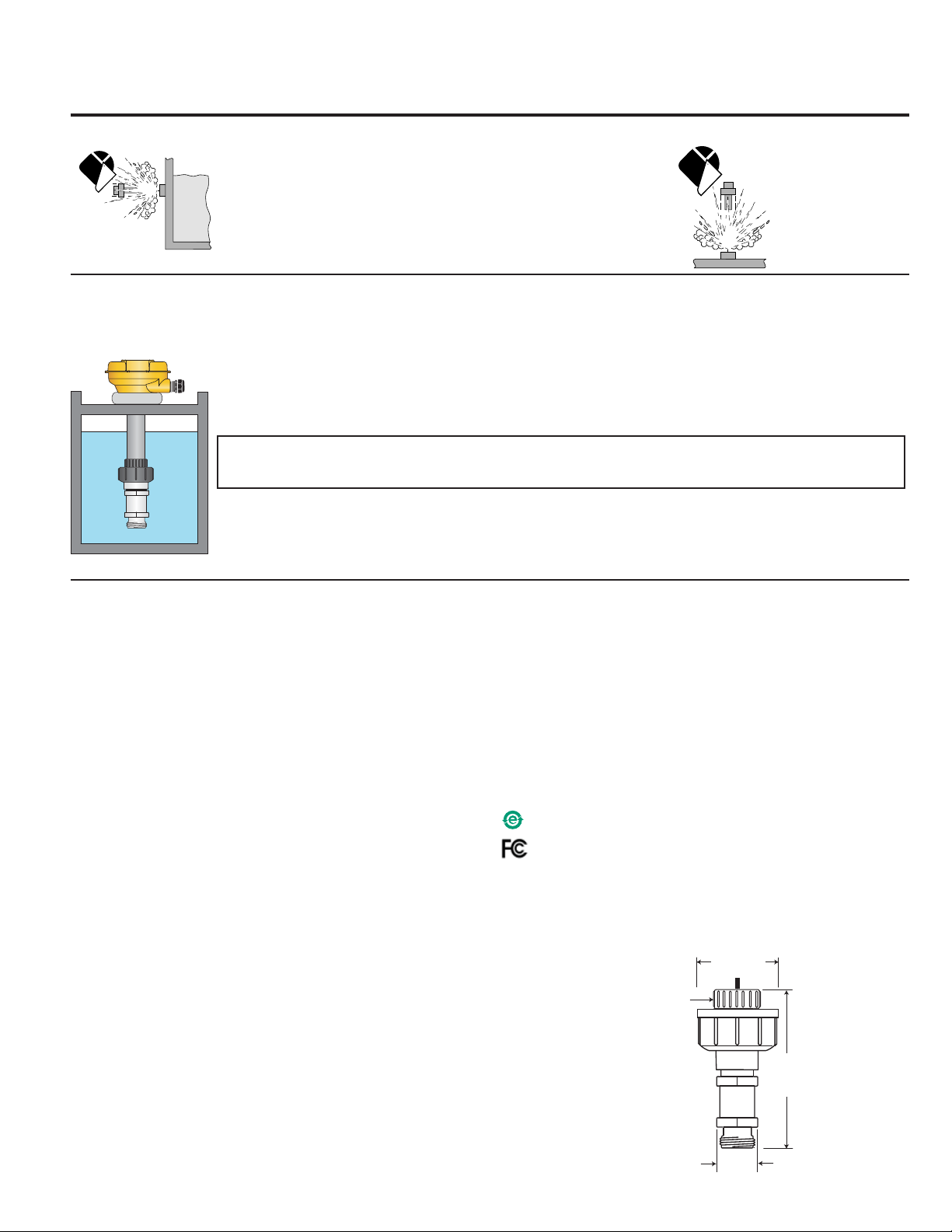
4. Wear safety goggles or faceshield during installation/service.
5. Do not alter product construction.
6. Dispose of properly; DO NOT INCINERATE!
1. Description
The Signet 2250 Hydrostatic Level Sensor uses a gauge pressure sensor to calculate the level of fl uid in a tank.
Gauge pressure sensors measure the difference in pressure between the process on one side of a diaphragm and the atmospheric
pressure on the opposite side of the diaphragm. A tiny capillary tube running from inside the sensor body and
up the length of the cable provides the reference to atmospheric pressure.
Hydrostatic level measurement can be a simple and practical solution to those applications where the fl uid
temperature is stable and constant.
IMPORTANT! This method of level measurement is not recommended if the fl uid is subject to
temperature variations or any other variable that causes the density of the fl uid to change.
The 2250 Hydrostatic Level Sensor has excellent chemical compatibility.
The wetted materials are PVDF, Ceramic and FPM.
Several different hardware mounting kits are available to accommodate every installation requirement.
2. Specifi cations
General
Compatibility: Signet 8900 Multi-Parameter Controller
Signet 9900 Transmitter
Wetted Material
• Sensor housing: PVDF
• Union nut/bushing: PVC-U
• Diaphragm: Ceramic
• Diaphragm seal: FPM (optional EPDM)
Cable type: 22 AWG, 3 conductor+capillary tube
Cable length: 10 m (32.8 ft) supplied
max. extension 120 m (400 ft)
Operating Temperature: 15 °C to 85 °C (5 °F to 185 °F)
Storage Temperature: -20 °C to 100 °C (-4 °F to 212 °F)
Operating Pressure: -XU: 0 to 0.7 bar (0 to 10 psig)
-XL: 0 to 3.4 bar (0 to 50 psig)
Electrical
Digital (S
• Format: Serial ASCII, TTL level 9600 bps.
• Accuracy: ±1% of full scale (±0.001 psi)
• Power: 5 VDC nominal, 1.5 mA max. current
(5 VDC min, 6.5 VDC max)
• Reverse polarity and short circuit protected
4 to 20 mA Output:
• Factory span:
• Accuracy: ± 32 μA
• Resolution: < 5 μA
• Response Time: < 100 ms
3
L) Output:
• -XU: 0 to 0.7 bar (0 to 10 psig) =
0 m to 7 m (0 ft to 23 ft) of water
• -XL: 0 to 3.4 bar (0 to 50 psig) =
0 m to 34 m (0 ft to 115.5 ft) of water
• Loop Power Required: 12 to 24 VDC nominal, 22.1 mA max
(10.8 VDC min. to 26.4 VDC max.)
• Max. Loop Impedance:
100 Ω @ 12 V
325 Ω @ 18 V
600 Ω @ 24 V
Standards and Approvals:
• CE
• RoHS Compliant
• Manufactured under ISO 9001 for Quality,
ISO 14001 for Environmental Management and
OHSAS 18001 for Occupational Health and Safety.
China RoHS (Go to www.gfsignet.com for details)
This device complies with Part 15 of the FCC rules.
Operation is subject to the following two conditions:
(1) This device may not cause harmful interference, and,
(2) This device must accept any interference received,
including interference that may cause undesired operation.
Dimensions
½ in. (ANSI) or
25 mm (ISO)
Solvent Socket,
PVC-U
53 mm
(2.09 in)
115 mm
(4.55 in)
34 mm
(1.32 in)
Page 2
Installation
IMPORTANT!
A tiny capillary tube inside the sensor body is used to ensure that the back of the diaphragm remains at atmospheric pressure.
If the capillary tube is blocked or damaged, the sensor cannot operate properly.
• If moisture is allowed to propagate down this tube to the rear of the diaphragm, the sensor may be damaged.
• Do not allow the cable to be bent or compressed.
• The ceramic diaphragm in the 2250 can be permanently damaged by over-pressure conditions or by mechanical contact.
HANDLE THESE SENSORS WITH CARE.
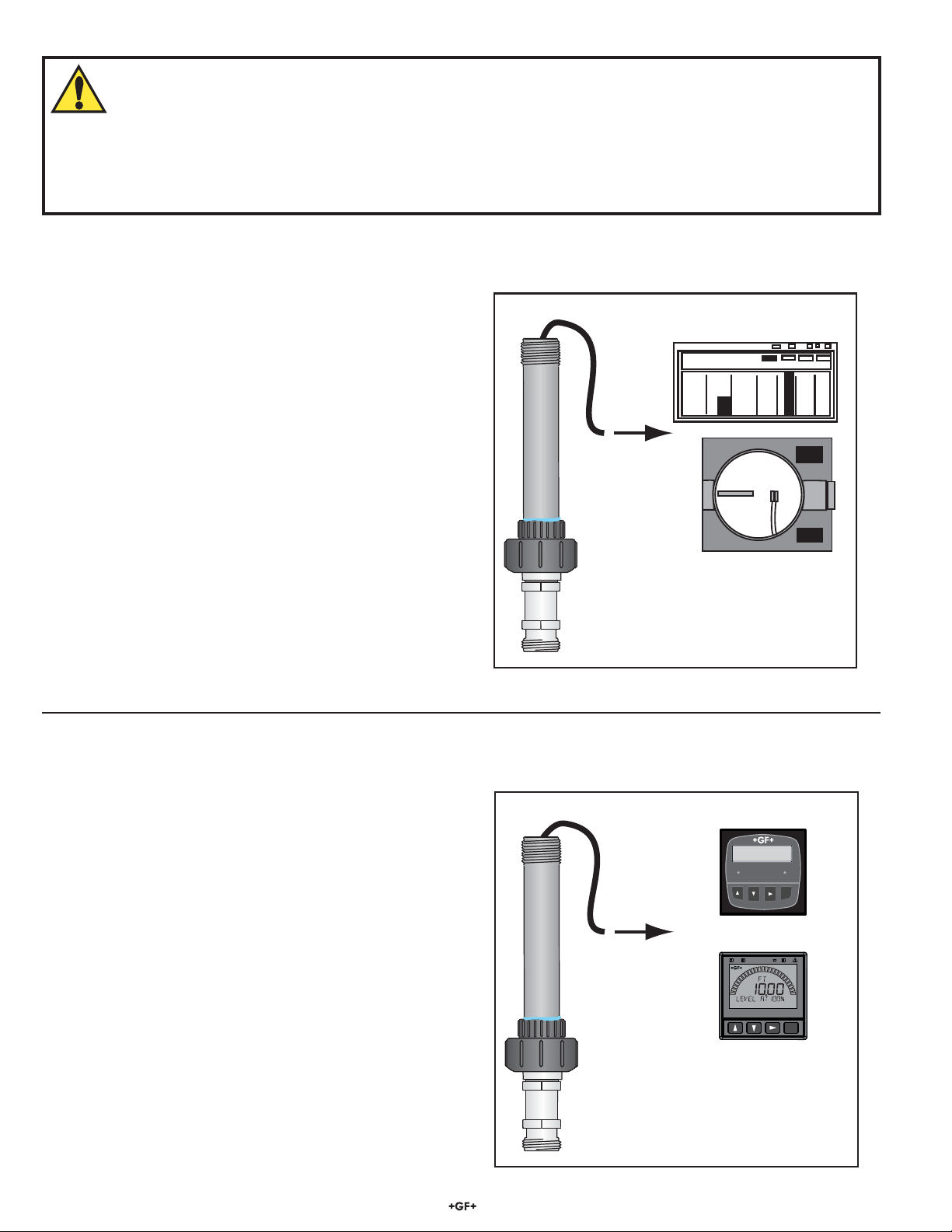
Direct 4 to 20 mA output
The 2250 can be assembled as a blind 4 to 20 mA signal connected
by cable to a PLC, chart recorder or other 4 to 20 mA device.
This type of installation requires no additional hardware.
The user must provide the ¾ in. conduit to protect the cable from
PLC
damage. The 2250 cable is not suitable for direct submersion.
4 to 20 mA
The 2250 can be assembled as a digital sensor connected
directly to a Signet 8900 Multi-Parameter Controller or Signet
9900 Transmitter.
3-2250-2xx-x
Direct Digital output
Digital (S
C1 2.50 μS/cm
L2 58.43 M
Multi-Parameter
Controller
Relay 1
Relay 2
ENTER
3-8900
3
L)
ENTER
3-9900
3-2250-1xx-x
2 2250 Hydrostatic Level Sensor
Page 3
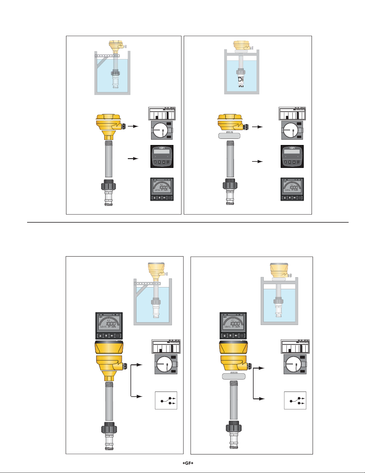
2250 with 4 to 20 mA or Digital (S3L) Output: Remote Mounting
The 2250 can provide a digital (S3L) signal to a 9900 Transmitter or 8900 Multi-Parameter Controller.
The 2250 can provide a 4 to 20 mA signal to a PLC or to a chart recorder.
4-20 mA or Digital (S3L) signal out
Clamped to Tank support
3-8052-1
4-20 mA Out
OR
Digital (S3L)
¾ in. conduit
(customer supplied)
3-2250-xx
PLC
C1 2.50 μS/cm
L2 58.43 M
Relay 1
3-8900
3-9900
Multi-Parameter
Controller
4-20 mA or Digital (S
Mounted through Tank Cover
3-8050-1
Relay 2
ENTER
ENTER
¾ in. conduit
(customer supplied)
3-2250-xx
3
L) signal out
4-20 mA Out
OR
3
Digital (S
PLC
C1 2.50 μS/cm
L2 58.43 M
L)
Multi-Parameter
Controller
Relay 1
Relay 2
ENTER
3-8900
ENTER
3-9900
2250 with Digital Output: Integral mounting
The 2250 can be assembled as an integral system, with the 3-9900-1 Transmitter mounted directly atop the sensor. This confi guration
provides a local display at the measurement site, plus the 4 to 20 mA and open-collector output features of the 9900 Transmitter.
Integral Transmitter
Clamped to Tank support
3-9900-1
3-8052
¾ in. conduit
(customer supplied)
3-2250-X
ENTER
4-20 mA Out
AND
Control Relay Out
Integral Transmitter
Mounted through Tank Cover
3-9900-1
PLC
3-8050
NC
C
NO
¾ in. conduit
(customer supplied)
3-2250-XX
ENTER
4-20 mA Out
Control Relay Out
PLC
AND
NC
C
NO
32250 Hydrostatic Level Sensor
Page 4

2250 Assembly Detail
1.
Glue the union bushing onto the conduit.
2.
Thread the sensor cable through the O-ring, Union
and through the ¾ in. conduit.
3.
6A.
Remote system
Cut the cable to length and terminate
the wires at the terminal block inside the
conduit base.
CAUTION
The capillary tube that runs
the length of the sensor
cable must remain open to
the atmosphere. Do not allow
it to be crimped or blocked.
4-20 mA Out
OR
Digital (S
3
L)
PLC
C1 2.50 μS/cm
L2 58.43 M
Multi-Parameter
Relay 1
3-8900
Controller
Relay 2
ENTER
ENTER
3-9900
Thread the Union nut onto the Union bushing.
CAUTION
Hand tighten the nut. Do not use tools.
4.
Thread the ¾ in. conduit adapter or the
universal adapter onto the top of the
conduit. Use a suitable thread sealant to
provide a watertight connection.
5.
6B.
Integral system
Cut the cable to length and terminate
the wires at the terminal block of a
fi eld-mounted 9900-1 Transmitter.
CAUTION
The capillary tube that runs the
length of the sensor cable must
remain open to the atmosphere.
Do not allow it to be crimped or
blocked.
4-20 mA Out
PLC
AND
Mount the conduit base onto the adapter and
secure the assembly with the locking ring.
C
Control Relay Out
4 2250 Hydrostatic Level Sensor
NC
NO
Page 5

Digital (S3L) wiring
• 3-2250-11X-X options provide Digital (S3L) output when powered with 5 VDC from a 9900 Transmitter or a 8900 Multi-Parameter Controller.
• Connecting the SHIELD to a direct Earth ground may reduce electrical noise interference.
• The maximum Digital (S
Consult the instrument manual for details.
3-2250-11X-X to 8900 Multi-Parameter Controller
Digital (S3L) Sensors
3-2250-11U
3-2250-11L
3-2250-11U-1
3-2250-11L-1
3
L) cable length is dependent upon the instrument to which the sensor is connected.
Lvl1 4.20 m
Black
White
Lvl2 8.53 m
Multi-Parameter
Controller
Relay 1
Red
Relay 2
ENTER
Shield
I/O Module 3-8900.401-X
Frequency
Input
Frequency
Input 2
OR
S3L
Input
S3L
Input
1
+5VDC (Black)
Freq. Input (Red)
1
GND (Shield)
+5VDC (Black)
Freq. Input 2 (Red)
2
GND (White/Shield)
+5VDC (Black)
GND (White/Shield)
Analog Output 1
(if applicable)
Analog Output 2
(if applicable)
3
S L (Red)
3
S L (Red)
3-8900.621C
1
2
3
4
5
6
7
8
9
10
11
+
12
-
13
+
14
-
Optional
Earth ground
3-2250-11X-X to 9900 Transmitter
Digital (S3L) Sensors
3-2250-11U
3-2250-11L
3-2250-11U-1
3-2250-11L-1
V+
DATA
SHLD
GND
Shield
White
Red
Black
ENTER
52250 Hydrostatic Level Sensor
Page 6

4 to 20 mA Loop Wiring
• The 3-2250-21X-X models provide a 4 to 20 mA loop output when powered with 24 VDC.
• Connecting the SHIELD to a direct Earth ground may reduce electrical noise interference.
Black (Loop +)
Red (no connection)
White (Loop -)
Cable shield
Optional Earth ground
Programmable Logic
Controller (PLC)
4-20 mA Loop Monitor
Chart Recorder
Datalogger
4 to 20 mA Sensors
3-2250-21U
3-2250-21L
3-2250-21U-1
3-2250-21L-1
Power Supply
+
DC 12 - 24 V
-
+
-
4 to 20 mA Span
The 2250 is available in two factory-set span ranges:
• Models numbers ending with "U" or "U-1" have a factory span of 0 to 10 psig.
• Model numbers ending in "L" or "L-1" are spanned for 0 to 50 psig.
The chart below lists the factory span of all available models.
The level ranges in meters and feet are based on the mass of water.
Mfr. Part No. Code 4 to 20 mA Span
3-2250-21U 159 001 248 0 to 0.7 bar (0 to 10 psig) 0 m to 7 m (0 ft to 23.09 ft)
3-2250-21L 159 001 247 0 to 3.4 bar (0 to 50 psig) 0 m to 34 m (0 ft to 115.5 ft)
3-2250-21U-1 159 001 482 0 to 0.7 bar (0 to 10 psig) 0 m to 7 m (0 ft to 23.09 ft)
3-2250-21L-1 159 001 483 0 to 3.4 bar (0 to 50 psig) 0 m to 34 m (0 ft to 115.5 ft)
6 2250 Hydrostatic Level Sensor
Page 7

Respanning the 4 to 20 mA output
• The 4 to 20 mA span can be set to accommodate any application within the operating range of the sensor.
• The respanning procedure requires that the sensor be subjected to the actual pressure that will represent 4 mA and 20 mA.
• The procedure illustrated here assumes that the application requires that the sensor output is 4 mA when the tank is empty
and 20 mA
when the tank is full. To reverse the range, reverse steps 3 and 5.
1. 2.
Black (Loop +)
Red (no connection)
White (Loop -)
+
Power Supply
-
DC 12 - 24 V
Install the sensor.
3.
= 4 mA
Fill tank to the level
represented by 4 mA.
= 20 mA
Programmable
Logic Controller
4-20 mA loop monitor
Chart Recorder
Datalogger
Wire the 4-20 mA Loop and turn the power ON.
4.
Carefully remove the heat shrink tube that is protecting
the red wire.
Short the RED and WHITE wires together for 15 seconds.
mA should go to 3 to 6 mA
Disconnect red wire
Black (Loop +)
Red (no connection)
White (Loop -)
Programmable
Logic Controller
4-20 mA loop monitor
Chart Recorder
Datalogger
6.5.
Black (Loop +)
Red (no connection)
White (Loop -)
+
-
+
Power Supply
DC 12 - 24 V
-
+
-
15s
+
Power Supply
DC 12 - 24 V
-
Wire Nut
WARNING!
Not protecting the
red wire may cause
the 4 to 20 mA
span to be reset.
Fill the tank to the level to be
represented by 20 mA.
Programmable
Logic Controller
4-20 mA loop monitor
Chart Recorder
Datalogger
Short the RED and BLACK wires together for 15 seconds.
mA should go to 22 mA
Disconnect red wire
After adjusting the 4 to 20 mA span, protect the red wire by
installing the provided wire nut.
For easier re-spanning use the Signet 0250 USB to Digital (S
Configuration/Diagnostic Tool.
+
-
15s
3
L)
72250 Hydrostatic Level Sensor
Page 8

Ordering Information
Sensor Part Number
3-2250 Hydrostatic Level Sensor
Sensor Output
-1 Digital (S
-2 Current (4 to 20 mA), 10m (32.8 ft.)
Threaded Connection
1 ½ in. union connector
3-2250 -1 1 U Example Part Number
2250 Hydrostatic Level Sensor
Mfr. Part No. Code Description
3-2250-11U 159 001 242 0 to 0.7 bar (0 to 10 psi), Digital (S
3-2250-11L 159 001 241 0 to 3.4 bar (0 to 50 psi), Digital (S3L), ½ in. union, ¾ in. PVC-U Union
3-2250-21U 159 001 248 0 to 0.7 bar (0 to 10 psi), 4 to 20 mA, ½ in. union, ¾ in. PVC-U Union
3-2250-21L 159 001 247 0 to 3.4 bar (0 to 50 psi), 4 to 20 mA, ½ in. union, ¾ in. PVC-U Union
3-2250-11U-1 159 001 478 0 to 0.7 bar (0 to 10 psi), Digital (S
3-2250-11L-1 159 001 479 0 to 3.4 bar (0 to 50 psi), Digital (S3L), ½ in. union, Metric PVC-U Union
3-2250-21U-1 159 001 482 0 to 0.7 bar (0 to 10 psi), 4 to 20 mA, ½ in. union, Metric PVC-U Union
3-2250-21L-1 159 001 483 0 to 3.4 bar (0 to 50 psi), 4 to 20 mA, ½ in. union, Metric PVC-U Union
3
L), 10 m (32.8 ft.)
Operating Pressure Range
U 0 to 0.7 bar (0 to 10 psi)
L 0 to 3.4 bar (0 to 50 psi)
PVC-U Union Connection
- ¾ in. socket
-1 Metric pipe connector
3
L), ½ in. union, ¾ in. PVC-U Union
3
L), ½ in. union, Metric PVC-U Union
Accessories and Replacement Parts
Mfr. Part No. Code Description
5523-0322 159 000 761 Sensor cable (per ft.). 3 conductor plus shield, 22 AWG (black/red/white/shield)
3-9000.392-1 159 000 839 Liquid tight connector kit, NPT (1 pc.)
3-9000.392-2 159 000 841 Liquid tight connector kit, PG 13.5 (1 pc.)
3-8050 159 000 184 Universal mount kit
3-8052 159 000 188 ¾ in. Integral mount kit
3-8050-1 159 000 753 Universal Mount w/Junction terminals
3-8052-1 159 000 755 ¾ in. Integral mount w/Junction terminals
3
3-0250 159 001 538 USB to Digital (S
L) Confi guration/Diagnostic Tool
Georg Fischer Signet LLC, 3401 Aero Jet Avenue, El Monte, CA 91731-2882 U.S.A. • Tel. (626) 571-2770 • Fax (626) 573-2057
For Worldwide Sales and Service, visit our website: www.gfsignet.com • Or call (in the U.S.): (800) 854-4090
For the most up-to-date information, please refer to our website at www.gfsignet.com
3-2250.090 Rev. E 06/13 English © Georg Fischer Signet LLC 2013
 Loading...