

Page 1
Instructions for GFB Short Shift Kit for STi 6 speed transmission
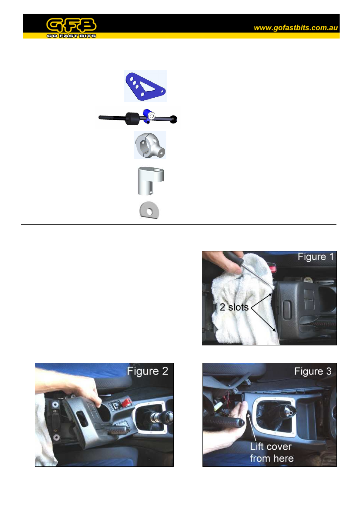
Included in kit:
• 2 x side plates
• 1 x gearstick
• 1 x linkage knuckle, including:
2 x M4 x 12 socket screws
• 1 x pin remover, including:
2 x M5 slot screws
• 2 x M8 washers
• 2 x M8 x 16 button head screws & nuts
• 2 x M5 x 8 button head screws
• 1 x 3mm hex key
• 1 x 4mm hex key
• 1 x 5mm hex key
• 1 x cable/zip tie
Required tools:
• 2 x 12mm spanner/wrench
• Medium flat-blade and phillips screwdriver
• Side cutters/knife
• Circlip pliers (or pointy needle-nose pliers
will suffice)
• Rag
We HIGHLY recommend you read through the instructions and familiarise yourself with the steps
before starting installation of this product.
1. Lift the lid of the centre console between the seats
above the handbrake. On the plastic handbrake shroud
there are two slots, using the flat-blade screwdriver
padded with a rag, carefully lever the shroud up on
each side (there is a pop-type fastener on each side).
2. Lift the handbrake shroud out (taking care of wiring
still attached), to give you access to the gearstick
surround (figure 2).
3. Unscrew the gear knob and unclip the button fastener
on the leather shift boot. Gently lift the plastic
gearstick shroud up from the back, it is only lightly clipped in and does not need much force.
Page 2
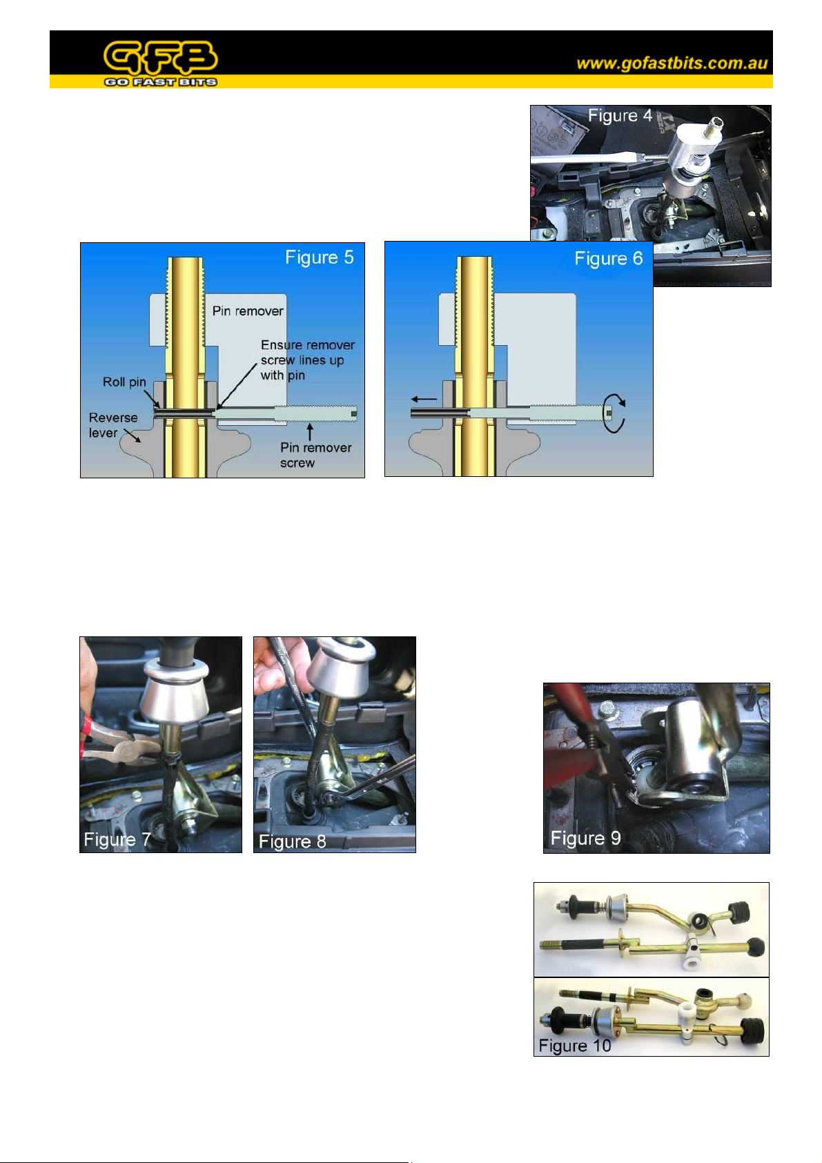
4. Slide the pin remover onto the top of the gearstick (fig. 4).
Thread the longer of the M5 slot screws into the threaded hole of
the pin remover, making sure to line up the end of this screw with
the roll pin as shown in figure 5. Watch the pin as you wind the
screw in, it should push easily out the other side (fig. 6). If not,
stop and check the screw is properly aligned with the pin.
5. Once the pin comes out completely, remove the screw and pin remover. The reverse lock cable will
spring down at this point, don’t worry, it will be retrieved during re-assembly.
6. Cut the cable tie that holds the reverse lock
cable to the gearstick (fig. 7). Using the two
12mm spanners, remove the bolt that holds the
linkage to the gearstick (fig. 8).
8. Transfer the ball cup and circlip to the GFB gearstick (the ball cup
spreads apart easily to allow this), making sure there is sufficient
grease in the cup. Remove the silver plastic boot collar (undo 2
phillips head screws from underneath), reverse lever, spring, and
rubber spring seat from the factory gearstick and fit them onto the
GFB gearstick (fig. 10). Slip the supplied steel sleeve into the
bushings in the GFB gearstick, again ensuring there is sufficient
grease on both parts.
9. Replace the assembled GFB gearstick back into the factory
position, and fasten it in place with the circlip.
7. Use the circlip (or needle-nose) pliers to
remove the circlip retaining the gearstick ball
cup (fig. 9). Pull up on the gearstick as you
close the circlip, it should lift out once the
circlip clears its groove. Pull the reverse lock
cable out of the gearstick as you lift it out.
Page 3

10. Fit the two parts of the linkage knuckle around the
factory shift linkage with the long side facing up (fig.
11). The top of the long side should lean towards the
back of the car. If it leans toward the dashboard, turn it
around the other way.
Place the two M4 screws into the holes and screw them
in until they are finger tight, making sure there is an
equal gap between both sides of the two parts.
11. Now loosen the left screw just enough to allow the
knuckle to be rotated horizontal (so that the two ends of
the knuckle are parallel to the sides of the shift linkage),
but DO NOT tighten it back up just yet.
12. Fix the two side plates to the linkage by first inserting
an M8 screw through the plate and then through the hole
in the shift linkage fork. Thread an M8 nut partially on,
but DO NOT tighten yet. Repeat on both sides (fig. 12).
13. On both side plates, insert an M5 screw through the
matching 5mm hole and thread it into the linkage
knuckle (fig. 12). Now tighten all screws and nuts. As
long as the lower M4 screw on the linkage knuckle was
set to the right distance as per step 10, you should only
have to tighten the top screw to clamp it up tight.
14. At this point it is necessary to lock the reverse cable in an extended position in order to be able to
replace the roll pin. To do this, pull on the cable and simultaneously twist the linkage clockwise, then
pull it back to select reverse. You may need to vary the distance you extend the cable to properly select
reverse. Once reverse is selected, the reverse cable should remain extended when you let it go. If you
have difficulty at this point, it may help to temporarily bolt the linkage to the gearstick (as shown in
figure 13) and use the gearstick to help select reverse. Make sure to leave the linkage in reverse until
the end of step 17.
15. If you have used the gearstick to assist in step 14,
it’ll help to unbolt it for this step. Slide the reverse
cable up into the top half of the gearstick. The hole
in the swage at the end of the cable should line up
with the slot in top of the gearstick (twist the cable
or rotate the gearstick if necessary). Line up the
hole in the reverse lever, then push the longer of the
M5 slot screws (the one used in step 4) through the
reverse lever, the gearstick, into the reverse cable
swage, and out the other side (fig. 14). This step will
line up all the parts and helps to guide the roll pin in
easily. If the reverse cable does not reach high
enough to push the pin through, re-check step 14.
Page 4

16. Put the pin remover back onto the gearstick, and drop the roll pin into the threaded hole, followed by the
shorter of the two M5 slot screws. Make sure the end of the roll pin is lined up with the end of the long
M5 slot screw, then begin screwing it into the gearstick (fig. 15). If aligned correctly, the roll pin will
push the longer M5 slot screw out of the gearstick as it is pushed in. Continue until the pin is pushed
about 1mm BEYOND centre. Now unwind the short M5 slot screw, spin the roll pin remover 180
degrees and push the pin back the other way until it is centred (fig. 16). This will ensure the end of the
cable is held in the middle of the gearstick, instead of rubbing against the side (look down the hole in the
top of the gearstick, you will be able to see the position of the cable).
17. Check the operation of the reverse lever, then fasten the reverse cable with the supplied zip tie.
18. At this point you will need to decide how short you want the
shift throw to be. This is determined by the height of the
clamp on the gearstick relative to the pivot ball – the higher
the clamp, the shorter the throw (Note: the shorter you make
the throw, the more force will be required to shift, this is
normal). The 3 holes in the blue plates simply ensure that
the gearbox linkage remains at the correct angle (so it
doesn’t foul on the transmission tunnel) regardless of the
clamp position. We suggest beginning with the middle hole.
Make sure the factory steel sleeve is inserted into the white
bushings of the gearstick clamp, then line up the sleeve with
the middle hole. Hold one of the M8 washers between the sleeve and the side plate, then slide the
factory bolt through the side plate, the washer, and into the sleeve. Note that you may have to adjust the
height of the clamp on the gearstick to get the bolt through the holes. Position the second washer on the
other side (fig 13), and push the bolt fully through. Partially thread the nut onto the end of the bolt,
tighten the screw in the gearstick clamp and test the shift feel. If the throw is too short or long, make an
adjustment to the height of the clamp, and if necessary, select a different hole on the side plates so that
the gearbox linkage does not rub or foul in any gear.
Note that as you slide the clamp up and down, the neutral position of the gearstick will move slightly.
By using the combination of the clamp height and hole position, you can tailor the shift feel to your
liking. Once you are satisfied tighten the clamp screw and linkage bolt, then perform a final check to
ensure that you can select all gears (including reverse) smoothly, and without any binding. Replace the
plastic shrouds in the reverse order of removal.
GFB Short Shift Kits carry a lifetime warranty which covers faulty components or manufacturing. Warranty is limited only to the
repair or replacement of GFB products provided they are used as intended and in accordance with all appropriate warnings and
limitations. No other warranty is expressed or implied.
 Loading...