

Page 1
Instructions for GFB Short Shift Kit for MY97-07 WRX 5-speed
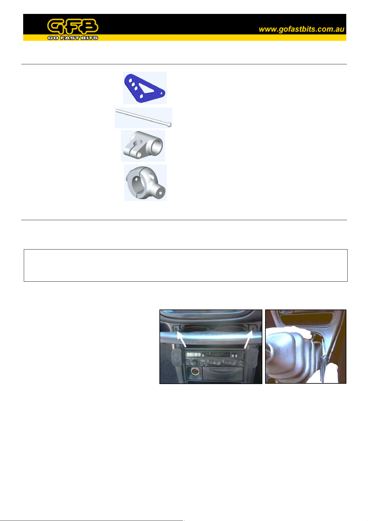
Included in kit:
• 2 x side plates
• 1 x shift stick
• 1 x shift pivot
• 1 x linkage knuckle,
including:
2 x M4 x 12 socket screws*
2 x M4 x 8 socket screws**
* These parts are used only on MY01-07 (GDA) models
** These parts are used only on MY97-00 (GC8) models
• 2 x M8 x 16 button head screws with nuts
• 2 x M8 washers*
• 2 x M5 x 8 button head screws
• 1 x M8 x 55 bolt**
• 1 x 3mm hex key
• 1 x 4mm hex key
• 1 x 5mm hex key
• M12 x 1.25 threaded nut
• Steel sleeve**
Required tools:
• 12mm spanner
• Shifting spanner
• Flat-blade screwdriver
• Large hammer or mallet
• Phillips head screwdriver (MY97-00)
GFB Short Shift Kits carry a 12 month warranty from the date of purchase which covers faulty components or
manufacturing. Warranty is limited only to the repair or replacement of GFB products provided they are used as
intended and in accordance with all appropriate warnings and limitations. No other warranty is expressed or implied.
1. Unscrew the gear knob and remove the plastic surrounds from the gearstick following the appropriate
instructions below for your year model.
• MY97-98 – Open the cup holder tray
and remove the two Phillips head
screws found behind (figure 1), then
gently lift the rubber gearstick boot at
the front corners to expose another two
Phillips head screws (figure 2). Remove
these also and the surround will lift off.
Figure 1 Figure 2
• MY99-00 – Lift the lid of the centre console, and remove the two Phillips head screws that hold down
the handbrake shroud. Lift the handbrake shroud off (it clips in at the front), and then the gearstick
surround simply clips off.
• MY01-07 - Lift the lid of the console between the seats above the handbrake. On the plastic handbrake
shroud there are two slots, using the flat-blade screwdriver padded with a rag, carefully lever the shroud
up on each side (there is a pop-type fastener on each side). Lift the handbrake shroud out, giving you
access to the gearstick surround. Simply lift the plastic shroud off, it is only lightly clipped in and does
not need much force.
Page 2
2. Using the 12mm spanner and shifter, undo and remove the bolt
that holds the linkage to the shift stick.
3. Remove the factory shift stick by levering the ball out of the
socket. Simply push the top of the stick towards the back of the
car until it pops out (figure 3).
Figure 3
4a) IMPORTANT: The linkage knuckle is designed to fit the two different diameter shafts that are found
in different models and as such, it comes with two
different length pairs of screws. For all MY00 and
earlier models (16mm diameter shaft), use the shorter
pair of screws (M4 x 8), and for all later models
(19mm diameter shaft), use the longer pair (M4 x 12).
Also note that a small handful of US MY02 models
came with the earlier shift mechanism, in which case
simply refer to the notes regarding early models.
b) Fit the two parts around the linkage with the long side
facing up (figure 4).
c) Place the two correct length M4 screws into the holes
and screw them in until there is no slack, making sure
there is an equal gap between both sides of the two
parts. Figure 4
d) Now loosen the left screw just enough to allow the knuckle to be rotated horizontal (so that the two ends
of the knuckle are parallel to the sides of the shift linkage), but DO NOT tighten it back up just yet.
5. Fix the two side plates to the linkage by first
inserting an M8 screw through the plate and
then through the hole in the linkage fork.
Thread an M8 nut partially on, but DO NOT
tighten yet. Repeat on both sides (figure 5).
6. On both side plates, insert an M5 screw
through the matching 5mm hole and thread it
into the linkage knuckle. Now tighten all
screws and nuts. As long as the lower M4
screw on the linkage knuckle was set to the
right distance as per step 4c, you should only
have to tighten the top screw to clamp it tight.
Figure 5
Page 3

7. Smear a small amount of grease onto the shift stick ball. Thread the
supplied M12 x 1.25 hex nut onto the threaded gear knob end, until
the top of the stick is just a fraction lower than the top of the nut.
This nut is used to protect the thread of the stick for the next step.
8. Holding the stick upright, press the ball against the socket and strike
the top of the M12 nut with a hammer to pop the ball into the socket
(figure 6). This takes a solid blow to achieve, so the heavier the
hammer, the easier it will be (slow pressure simply does not work).
This process will not damage the ball or the cup, as the cup is
designed to spread apart for assembly. Make sure to remove the M12
nut before continuing.
Figure 6
9. Slide the shift pivot onto the shift stick, then remove the urethane
bushes from the factory shift stick and insert them, along with
the suitable steel sleeve, into the GFB unit (NOTE: For
MY97-00 models, use the provided steel sleeve. For MY01-04
models, use the factory sleeve instead). DO NOT tighten the
screw to clamp the shift pivot to the stick just yet.
10. Decide on how short you want the shift (pick one of the three
holes in the side plates, the higher the hole, the shorter the
shift), as a guide GFB recommends using the middle hole to
begin with. Line up the steel sleeve in the shift pivot with the
selected hole, then hold one of the M8 washers between the
sleeve and the side plate (NOTE: For MY97-00 models do not
use the washers, the sleeve is the correct length to fit between
the plates. It is not possible to use the lowest hole setting in
MY97-00 models).
Figure 7
Slide the M8 bolt (use the supplied one for MY97-00, the factory one for MY01-current) through the
side plate, the washer, and into the sleeve (figure 7). Then hold the remaining washer in the same place
on the other side, and push the bolt through fully. Thread the nut onto the end and tighten.
11. Slide the shift pivot up and down until the factory linkage does
not hit the metal plate above it, or drag on the rubber boot
below, then re-tighten the screw firmly (figure 8). Do a final
check to ensure the linkage clears its surroundings in all gears.
12. Replace the plastic shrouds in the reverse order of removal.
NOTE:
• Always make sure that no part of the shift mechanism is contacting
any of the surroundings in all gears.
•
As the shift throw is reduced by a percentage, the principle of levers
means that the force required to shift gears is proportionally
increased. THIS DOES NOT MEAN IT WILL WEAR YOUR
GEARBOX! THE SHIFTER IS MERELY A LINKAGE TO
THE GEARBOX - DRIVER ABUSE IS THE ONLY THING
RESPONSIBLE FOR GEARBOX WEAR OR DAMAGE.
Figure 8
 Loading...