

Page 1

Mach 1 Blow-off Valve
Installation Instructions
P.O. Box 1017 Riverwood NSW 2210
Ph: +612 9534 0099 Fax: +612 9534 3999
Website: www.gfb.com.au Email: sales@gfb.com.au
Page 2
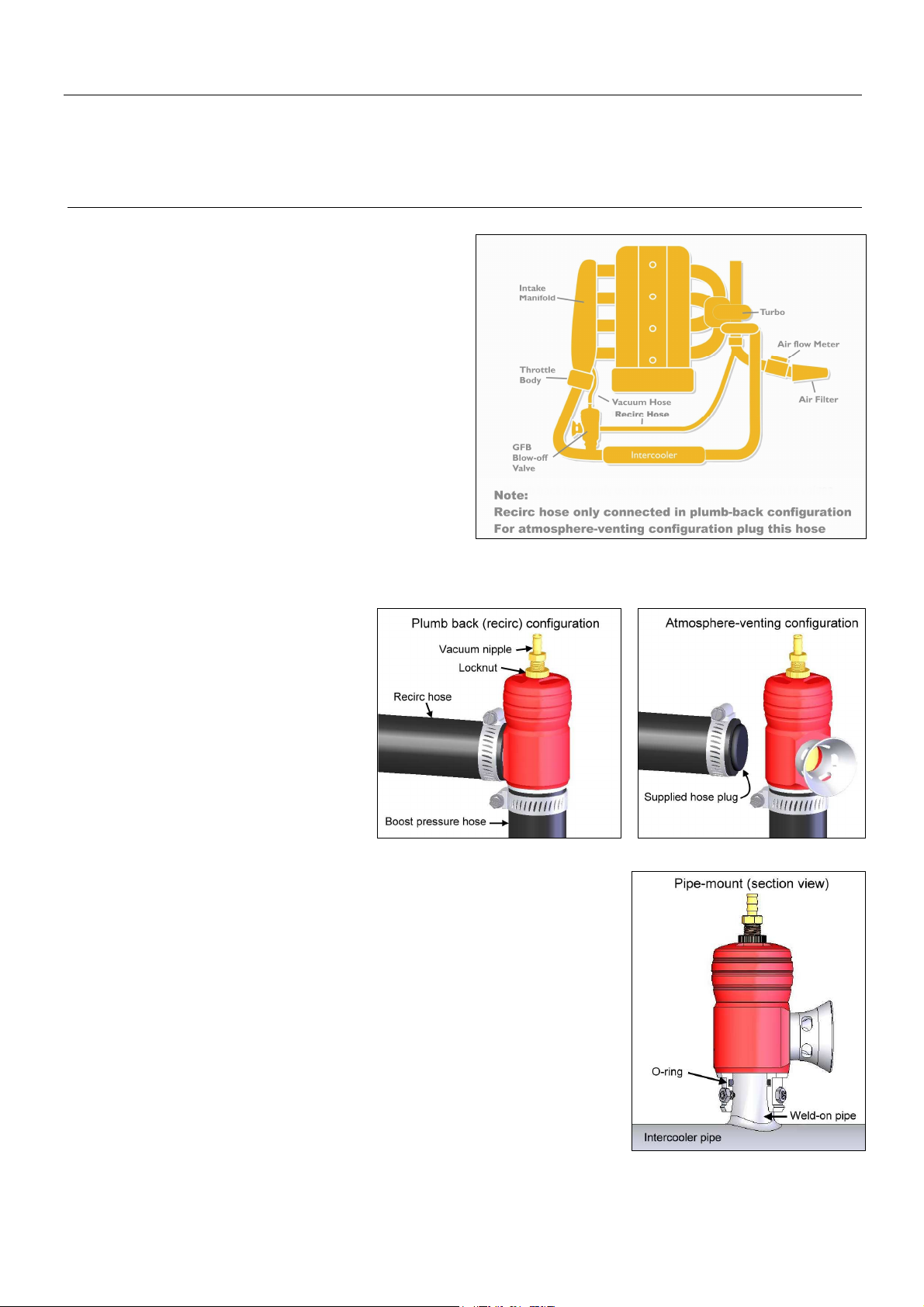
Installation Instructions for GFB Mach 1 Blow-off Valve
Included in kit (unless ordered with fittings other than standard):
• Mach 1 BOV, fitted w/ 35mm base & 30mm recirc outlet
• 1 x screw-in trumpet
• 1 x o-ring
The Mach 1 comes complete with all the parts required to set
it up as either a vent-to-atmosphere or a plumb back blow-off
valve. It comes pre-assembled in the atmosphere venting
configuration, and to switch to plumb back, you only need to
swap the trumpet for the supplied plumb back outlet.
Select the mode of venting you wish to use, and then begin the
installation by locating and removing the factory blow-off
valve, taking note of the hoses that connect to it. If the fittings
on your GFB Mach 1 do not match the factory hoses, or a bolton flange is required, check the adaptor listing at the end of
these instructions.
For cars without a factory blow-off valve, a suitable location
must be found on the inlet piping between the turbo and the
throttle body (see diagram opposite), and a hose or pipe
attached onto which to mount the Mach 1. The standard base
fitting of the Mach 1 can be mounted in two ways. It can
either be clamped into rubber/silicone hose, or it can be pipe mounted directly onto the turbo piping. These methods are
described below:
1) Hose mounting: The standard base
fitting of the GFB Mach 1 will fit inside 3236mm I.D. hose, and should be secured using a
hose clamp (not supplied). Make sure that the
supplied o-ring and grub screws are not used
for this application, and that the hose clamp
band is seated on the straight section of the
collar, rather than on the retaining bead.
For atmosphere venting configuration, plug the
factory recirc hose as shown using the plastic
plug supplied. If you choose the plumb back
configuration, connect the recirc hose to the
supplied plumb back outlet as shown.
2) Pipe mounting: For cars without an existing blow-off or diverter valve, weld
a short length of 1” O.D. pipe to a suitable location on the turbo piping as shown in the
schematic engine diagram above (and the pipe-mount configuration cut-away diagram
opposite). Also available from GFB are alloy and stainless steel weld-on adaptors to
suit different intercooler pipe materials.
If your car has a flange-mounted factory valve, GFB has a range of vehicle-specific
bolt-on flange adaptors - check the adaptor guide at the end of these instructions for
available types.
Insert the supplied o-ring into the internal groove in the base of your GFB valve as
shown, and partially thread the three grub screws into the tapped holes. Slide the valve
onto the 1” (25.4mm) O.D. pipe, making sure that the o-ring slides completely over the
end of the pipe, and then fasten the valve in place with the grub screws and lock nuts.
MAKE SURE TO MOUNT THE BOV IN A POSITION WHERE DIRT OR
WATER CANNOT FALL INTO THE VENTING OUTLET.
• 3 x M5 grub screws and nuts
• 1 x 30mm hose plug
Page 3

3) Depending on the configuration you choose to set up your GFB valve (vent-to-atmosphere or plumb back), ensure the
factory recirc hose that returns vented air to the intake is either plugged, or connected to your GFB valve’s outlet – do NOT
leave it open to the atmosphere. Various sized plugs and plumb back outlets are also available if required.
4) Connect the vacuum nipple on the top of the GFB valve to the inlet manifold AFTER the throttle body (see schematic
engine diagram). For best performance, where possible keep the hose run as short as possible and ensure that there are no
other accessories connected to this hose (such as fuel pressure regulator, brake booster, boost controller or boost gauge).
If you must connect other devices or increase the length of the hose, ensure that you use tee joins and vacuum hose with and
internal diameter of at least 4mm. Small diameter tee joins/hose or too many additional devices can slow the response of the
valve, or cause erratic performance.
Adjusting the spring pre-load
Contrary to popular belief, the spring DOES NOT need to be adjusted to hold different boost levels. The valve will stay shut
regardless of boost pressure or spring pre-load as long as the vacuum hose at the top receives the same full-throttle boost
pressure as the intercooler pipes. Rather, the spring adjustment changes how easily the valve opens when you close the
throttle, and how long it stays open when it vents. It is also used to accommodate variations in manifold vacuum levels on
different cars.
When the plumb back configuration is chosen, or your car does NOT have an airflow meter, the spring adjustment is not
critical and you can adjust it to suit your own preference. If your car does have an airflow meter AND you have chosen the
vent-to-atmosphere configuration, you will need to ensure the spring is set correctly, as follows:
Start by first loosening the locknut on the vacuum nipple (see second diagram on previous page) to allow it to turn easily. Set
the spring to the softest setting by turning the vacuum nipple anti-clockwise until you feel the turning resistance release. With
the car running at normal operating temperature, watch the piston through the venting outlet (not too closely!) as you stab the
throttle sharply and then release it. The piston should lift quickly and vent as you release the throttle, then close smoothly. It
should be completely closed by the time the engine drops back to idle.
If you notice any of the following symptoms, turn the nipple clockwise one turn at a time until the problem disappears:
• The piston is open at idle
• The valve continues to vent too long, causing the engine to “stumble” as it returns to idle speed (the revs may drop
below idle and then come back up again, or it may “hunt” for a stable idle RPM)
• When driving, the car stalls as you pull up to a stop
• When driving you notice a hesitation between gears or loud/excessive backfiring from the exhaust
If when driving a significant fluttering noise is heard (at full throttle or high RPM), turn the nipple anti-clockwise a few turns.
A little flutter can sometimes occur at lower RPM under certain conditions (or certain turbo systems), this is quite normal.
Note that the venting characteristics and sound of the valve can change in the first week or so, this is because the valve is
assembled using a protective grease which can slow the movement of the piston slightly during initial use.
Troubleshooting
Problem: The valve does not vent or blow off at all.
• Check the vacuum hose as described in section 4. Ensure that the hose you are using is indeed a vacuum source,
putting your finger over the end of it whilst the engine is running will tell you if it is or not.
• Check the orientation of the valve. Boost MUST enter the bottom of the valve, and dump through the side. This is
particularly important to check on Audi/VW engines, and any others that use plastic Bosch-style factory valves.
• Move the piston by hand to ensure it is not physically jammed or damaged.
• Set the spring to its softest setting.
Problem: The valve is leaking boost.
There are many symptoms that are often incorrectly interpreted to be a leaking valve. The design of the valve is such that
regardless of the boost pressure, if the car is at full throttle the pressure in the manifold should be the same as the pressure in
the intercooler piping. This means there is equal and opposite pressure pushing on the piston, which effectively cancels itself
out. So unless there is less pressure reaching the top of the valve via the vacuum connection, it will NOT open under boost.
Still got problems? For a comprehensive blow-off valve ‘Troubleshooting’ guide, visit our website (www.gfb.com.au) or
contact GFB directly on +612 9534 0099 or at
support@gfb.com.au.
Page 4

Maintenance
GFB products are designed and manufactured in a way that, in most circumstances, requires little or no regular maintenance.
Cleaning and/or disassembly are only necessary if the piston does not move smoothly or if there is damage from dirt or other
foreign objects. The following is a list of symptoms that might indicate cleaning is required:
• The venting sound becomes irregular or noticeably different
• The piston is covered with a sticky grey film
• The car begins to stall or idle badly where it didn’t previously
• Physical damage (vertical score marks) can be seen on the piston surface
To disassemble the Mach 1, use
a 1.5mm hex key to remove the
grub screw at the bottom of the
valve body. Unscrew the base,
taking care as the spring is preloaded with about 5kg of force,
and the valve will want to pop
apart as the base comes free.
Wipe all internal parts clean with a rag. Inspect the piston and bore for visual damage, then slide the piston into the bore dry to
check that it slides smoothly and freely. If any damage is found or the piston does not slide freely, contact GFB for advice.
Otherwise, smear the piston and bore with engine oil and re-assemble.
Accessories available
Base adaptors (screw on in place of existing base):
5020 – 20mm hose base
5025 – 25mm hose base
5030 – 30mm hose base
5035 – 35mm hose/1” pipe mount base (standard supplied base)
5038 – 38mm (1.5”) pipe mount base (compatible with Turbosmart adaptors)
Plumb back outlets (to replace trumpet):
5220 – 20mm
5225 – 25mm
5230 – 30mm (standard outlet supplied)
5233 – 33mm
Hose plugs:
5520 – 20mm
5525 – 25mm
5530 – 30mm (standard supplied plug)
5533 – 33mm
Model-specific flange adaptors:
5101 – MY99-00 WRX/Forester GT
5104 – R33/34 Skyline
5107 – MY03-04 Forester XT
5108 – MY01-07 WRX/STi, MY05-08 Forester XT
This product is intended for racing use only, and it is the owner’s
responsibility to be aware of the legalities of fitting this product in
his or her state/territory regarding noise, emissions and vehicle
modifications. GFB recommends that only qualified motor
engineers fit this product.
Materials and workmanship of this product are covered by a
lifetime warranty. Moving components subject to wear are covered
for a period of one year from the date of purchase. Warranty is
limited only to the repair or replacement of GFB products provided
they are installed and used as intended, and in accordance with all
applicable warnings and limitations. No other warranty is
expressed or implied.
GFB products are engineered for best performance, however
incorrect use or modification of factory systems may cause damage
to or reduce the longevity of the engine or drivetrain components.
5109 – S14 & S15 200SX
 Loading...