

Page 1
EX50 50mm External Wastegate
Installation Instructions
P.O. Box 1017 Riverwood NSW 2210
Ph: +612 9534 0099 Fax: +612 9534 3999
Website: www.gfb.com.au Email: sales@gfb.com.au
Page 2
GFB EX50 Wastegate
Packing list:
• Assembled EX50 50mm wastegate, fitted with:
o 1 x 13psi spring (60mm O.D.)
o 2 x V-band clamps
o 1 x outlet weld-on flange (part # 7041)
o 1 x inlet weld-on flange (part # 7051)
o Valve seat
Included in box:
• 2 x banjo hose connectors & 1/8” BSP bolts
Installation
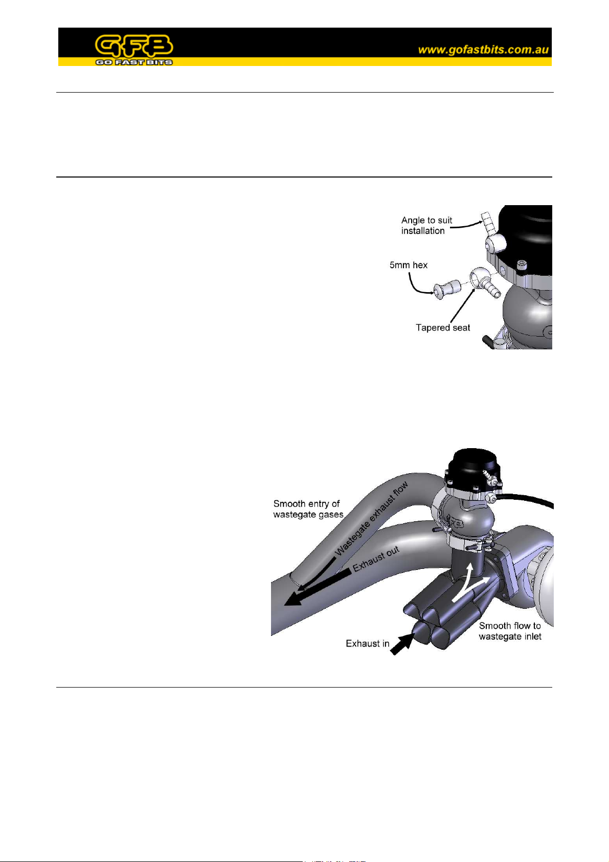
Install the boost nipples using a 5mm hex key, making sure that the head of
the banjo bolt sits into the large tapered seat on the banjo as shown. Position
the nipples in the best orientation for the installation. The thread is 1/8”
BSP, which is a commonly available thread should you wish to use a
different type of hose fitting.
Weld-on fittings:
stainless steel fittings, which need to be welded onto your turbo exhaust
manifold and exhaust system, onto which the EX50 is mounted using the
supplied v-band clamps. The inlet and outlet weld-on fittings are both
different, having been designed for the pipe that is most suitable for each
purpose.
The inlet fitting, which is welded to the exhaust manifold and supports the weight of the wastegate, is best suited to 1.5”
(48mm) nominal bore Schedule 10 or 40 pipe – a commonly available heavy-walled pipe. The outlet fitting is designed
to accept 2” (50mm) O.D. thin-walled pipe, which is commonly used for exhaust systems and screamer pipes. Of
course, it is possible to use different size and wall-thickness pipes than those recommended, provided a suitable weld
can be achieved. The weld-on fittings are available separately from GFB if required.
The inlet fitting should be welded to the exhaust
manifold after all the exhaust runners have
merged, and in a position that promotes smooth
flow to the wastegate – fast-moving exhaust gas
is reluctant to make sharp turns, which
significantly reduces the flow potential through
the wastegate. The diagram opposite shows a
suggested installation location.
On any street-driven car, the wastegate outlet
MUST be connected to the vehicle’s exhaust
system (before any catalytic converters and
mufflers), and should be done in a way that
allows the gases to merge smoothly. On race
cars where regulations allow, the outlet can be
routed out of the engine bay to atmosphere.
Already fitted to the EX50 you will find two
Setting up the EX50
Use the following guide to help set up your EX50. You should determine the minimum and maximum boost pressure
that you want to run (if you are not planning to vary the boost, then the minimum and maximum are the same), and your
control method.
Care should be taken when selecting boost pressures, and it is always best initially to err on the conservative side, until
the engine can be run on a dynamometer to ensure safety. Always consult an expert when making boost changes, and it
is recommended that the car be checked on a dyno, as high boost and/or lean air/fuel mixtures can cause engine damage
or worse, total failure.
Page 3

•
•
•
•
•
•
•
•
•
•
•
•
Spring Selection
The EX50 comes with a 13psi spring, and also available are 7
and 9psi springs, which can be used individually or installed
together to achieve different boost levels. Use the table
opposite to determine the combination of springs required for
your desired base boost level.
Note that this table is only a guide to help your selection – the
actual boost level achieved ultimately depends on a large
number of variables, and may differ from the base boost
pressure shown in the table.
If you are planning on having variable boost through the use of a boost controller, the range you can achieve depends on
your turbo setup. The lowest boost you can achieve is determined by the spring, and you may find that boost becomes
less stable if the difference between the peak boost and the lowest boost is significant. For example, a spring that gives
9psi could be adjusted with a boost controller to give 20psi, but it is likely that boost will not be as stable as it would be
using a 16 or 20psi spring combination.
Base Boost
Pressure (psi)
7
9
13
16
20
22
29
7psi
Inner
9psi
Middle
13psi
Outer
Changing the Spring
Use a metric 4mm hex key to remove 4 of the cap screws, leaving two opposing screws in place. Care must be taken
during this next step, as the spring force that is restrained by these two screws can exceed 50kg, depending on the
springs used.
Carefully remove the remaining two screws whilst restraining the cap to prevent it popping off. It is a good idea to have
a helper during this step, or better still, use a press to restrain the cap and allow you to remove it slowly.
Change the spring/s as required, and ensure they sit into the corresponding grooves in the cap. When re-installing the
cap, you can do so in any orientation to suit your purposes. Ensure the bead of the diaphragm is sitting into the groove,
then press the cap down and fully screw in two opposing cap screws, followed by the remaining four. Ensure the
screws are nipped up tight.
Boost Control Method
There are many different ways to connect the wastegate boost ports; three of the more common methods are shown
below. Whilst it is possible to use any number of different methods that are not shown here, you should always
remember the following:
• The lowest boost pressure possible is determined by the spring
• The lowest possible boost pressure for a given spring combination is achieved when the full boost pressure is
applied to the lower actuator port, and none to the upper port
• Boost pressure increases when you do one or both of the following:
o Decrease the pressure at the lower port (using a boost controller for example)
o Increase the pressure at the upper port
This is the most basic method, using a pressure hose from
a boost source (often found on the turbo outlet) connected
to the lower actuator port of the wastegate cap.
This configuration results in a boost pressure that is
dictated by the wastegate spring – you must change the
spring to alter the boost level.
The unused upper actuator port should be oriented so that
water and dirt cannot easily enter.
Page 4

The second configuration is a simple adaptation of the
above, with a boost controller (such as the GFB Atomic)
fitted into the pressure hose as shown to allow the boost
to be easily increased above the base level.
In the case of the Atomic boost controller, the arrow on
the body must point in the direction shown, or the
controller will have little effect.
If using a different brand controller, you should consult
the instructions for that product.
The third configuration is a typical installation for
electronic boost controllers.
You should consult your boost controller’s instruction
manual for specific information on how each of the ports
of the solenoid valve should be connected.
This product is intended for racing use only, and it is the owner’s responsibility to be aware of the legalities of
fitting this product in his or her state/territory regarding noise, emissions and vehicle modifications.
This product may not work if installed correctly, and as such GFB makes no warranty against engine failure
when using this device.
GFB products are engineered for best performance, however incorrect use or modification of factory systems
may cause damage to or reduce the longevity of the engine/drive train components.
Warranty is for the period of one year from the date of purchase and is limited only to the repair or replacement
of GFB products provided they are used as intended and in accordance with all appropriate warnings and
limitations. No other warranty is expressed or implied.
 Loading...